Theoretical Methodology of a High-Flux Coal-Direct Chemical Looping Combustion System

Abstract
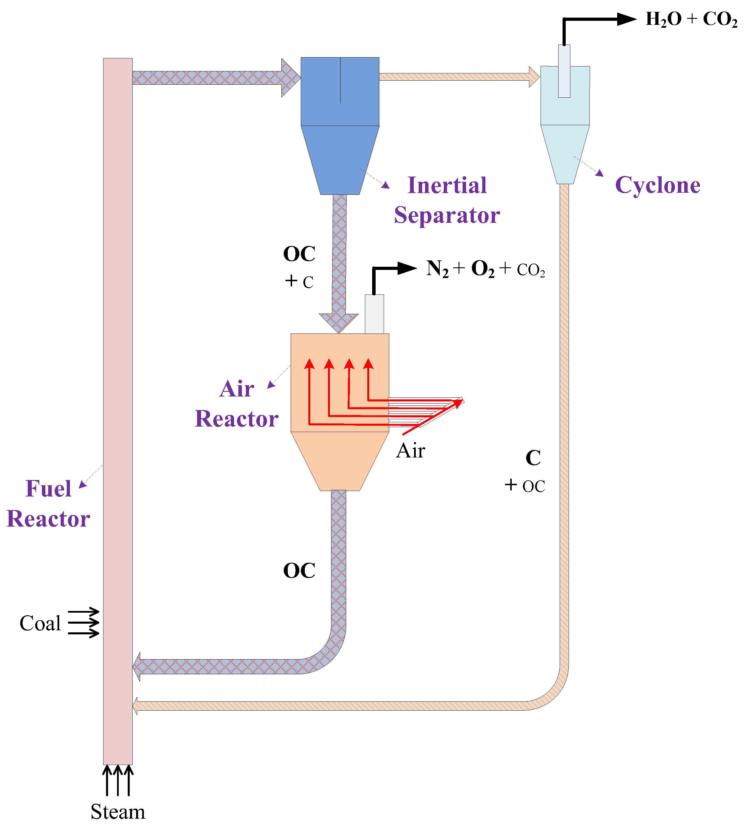
:1. Introduction
2. Materials and Methods
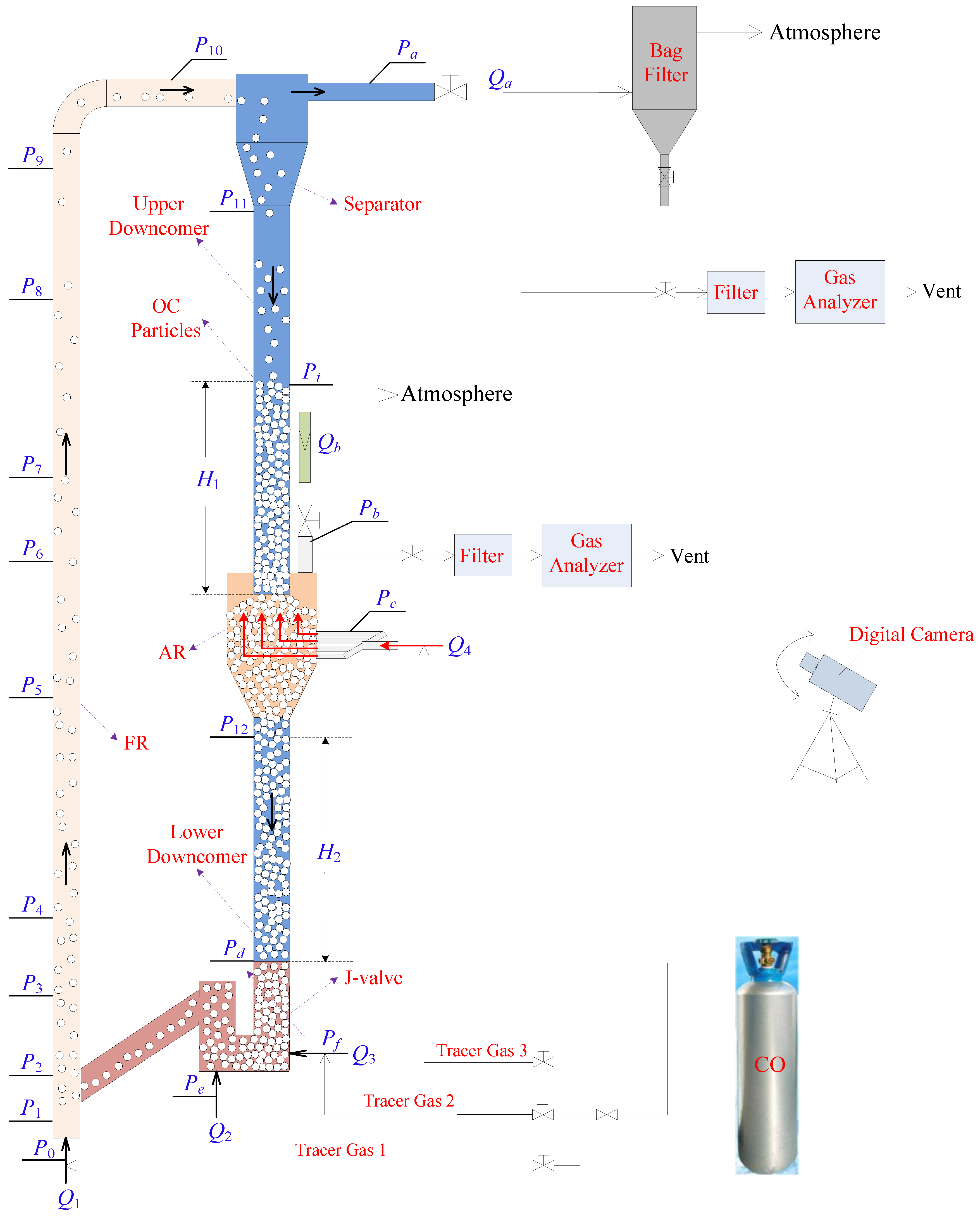
2.1. Visualization Experimental Device
2.2. Materials
2.3. Performance Indicators
3. Results and Discussion
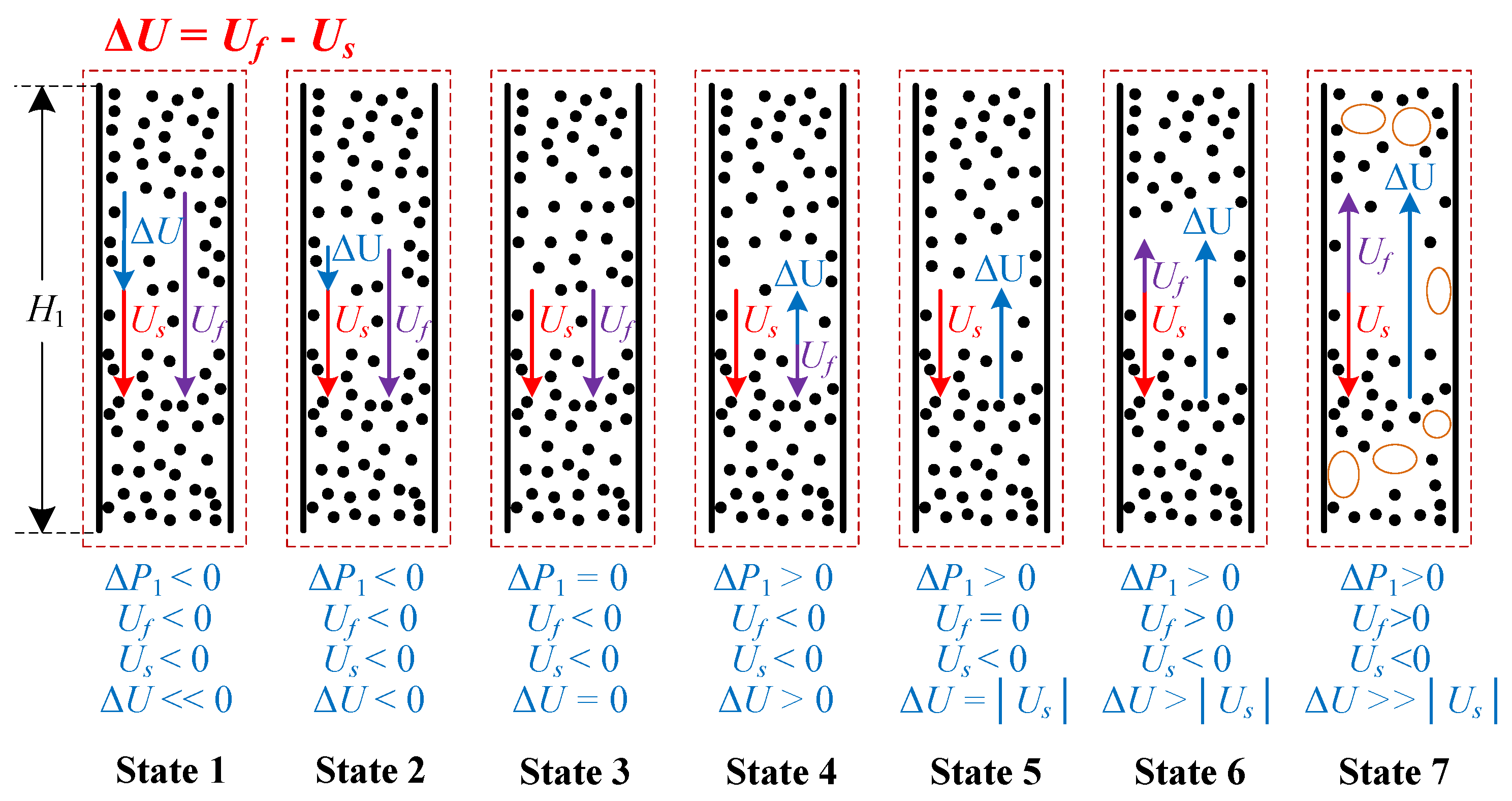
3.1. Gas–Solid Flow Characteristics
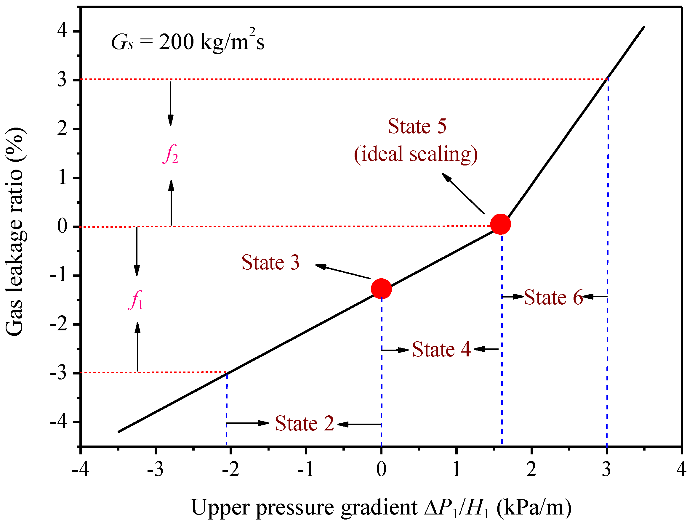
3.2. Theoretical Methodology for Gas Leakage Restraint
3.2.1. Semi-Theoretical Formulas of the Upper Pressure Gradient
3.2.2. Semi-Theoretical Formulas of the Lower Pressure Gradient
3.3. Theoretical Methodology for Circulation Stability
3.4. Theoretical Methodology Application to Condition Designs of the Cold System
3.5. Hot State Application Assessment of the Theoretical Methodology
4. Conclusions
- (1)
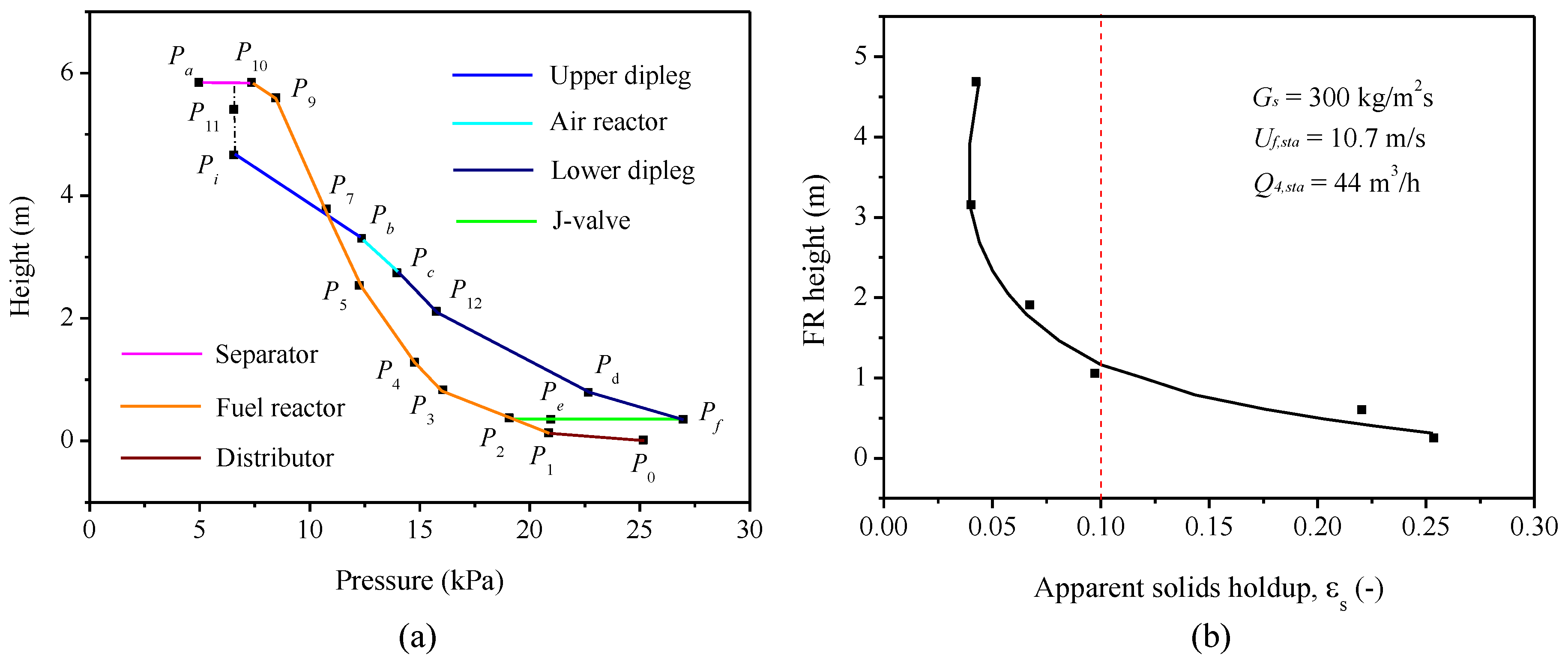
- During the CDCLC process, the dipleg flow can situate at a pressure region across the positive and negative pressure gradients, which can be categorized into seven flow states. Considering the gas leakages and the circulation stability, the upper dipleg of the AR was recommended to be operated among State 2 to 6 while the lower dipleg of the AR should better run between States 5 and 6.
- (2)
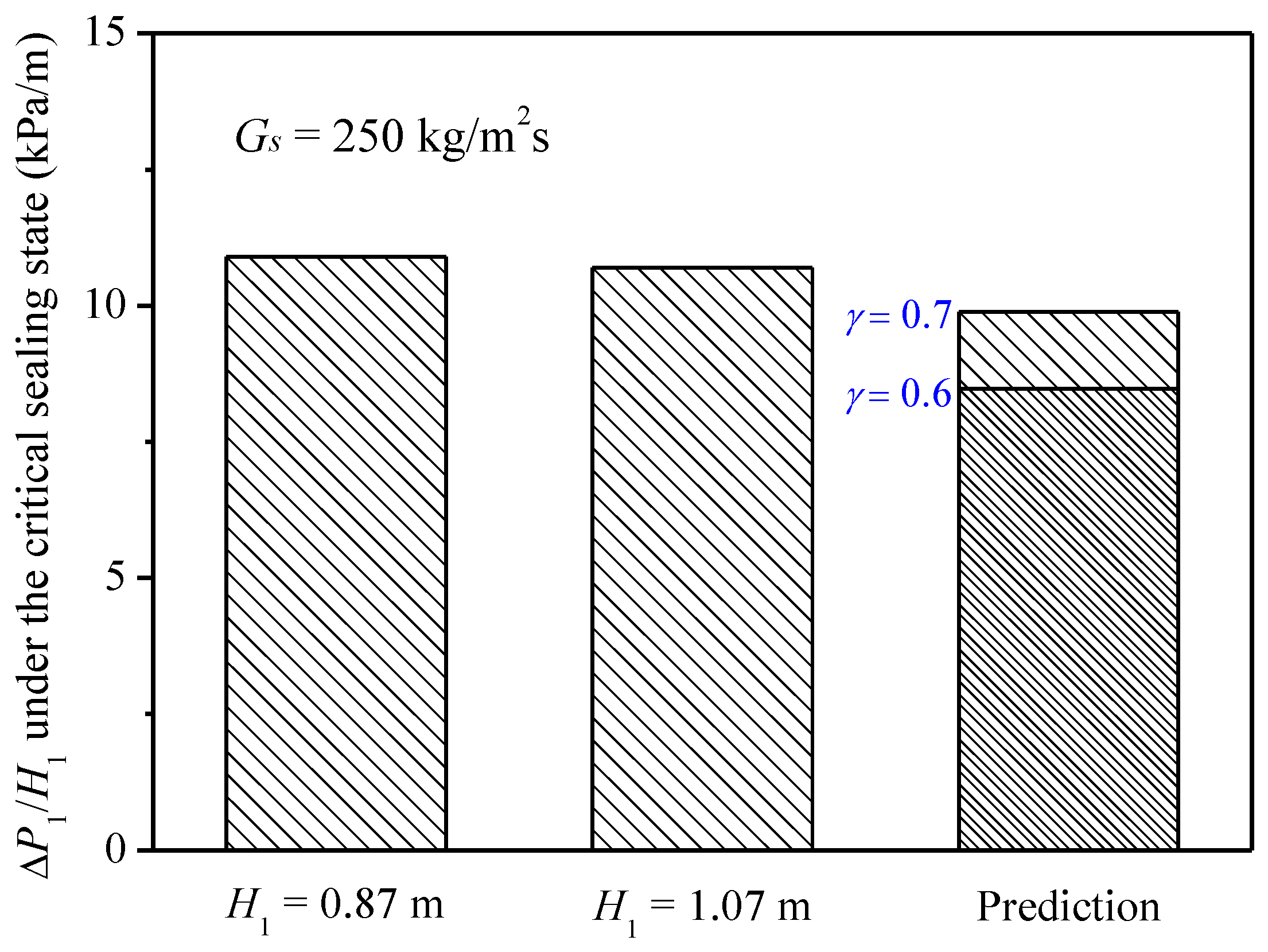
- The gas leakages between the two reactors were expressed as two conterminal linear equations with the ideal pressure gradient chosen as the boundary point, which can be used to predict the optimal regions of the upper pressure gradient. Similarly, the J-valve leakage within the optimal region was expressed as a linear function of the lower pressure gradient of the AR. In addition, an empirical formula of critical sealing was developed for this high-flux CDCLC system, which can be used to identify the advent of circulation collapse so as to guarantee the operation stability.
- (3)
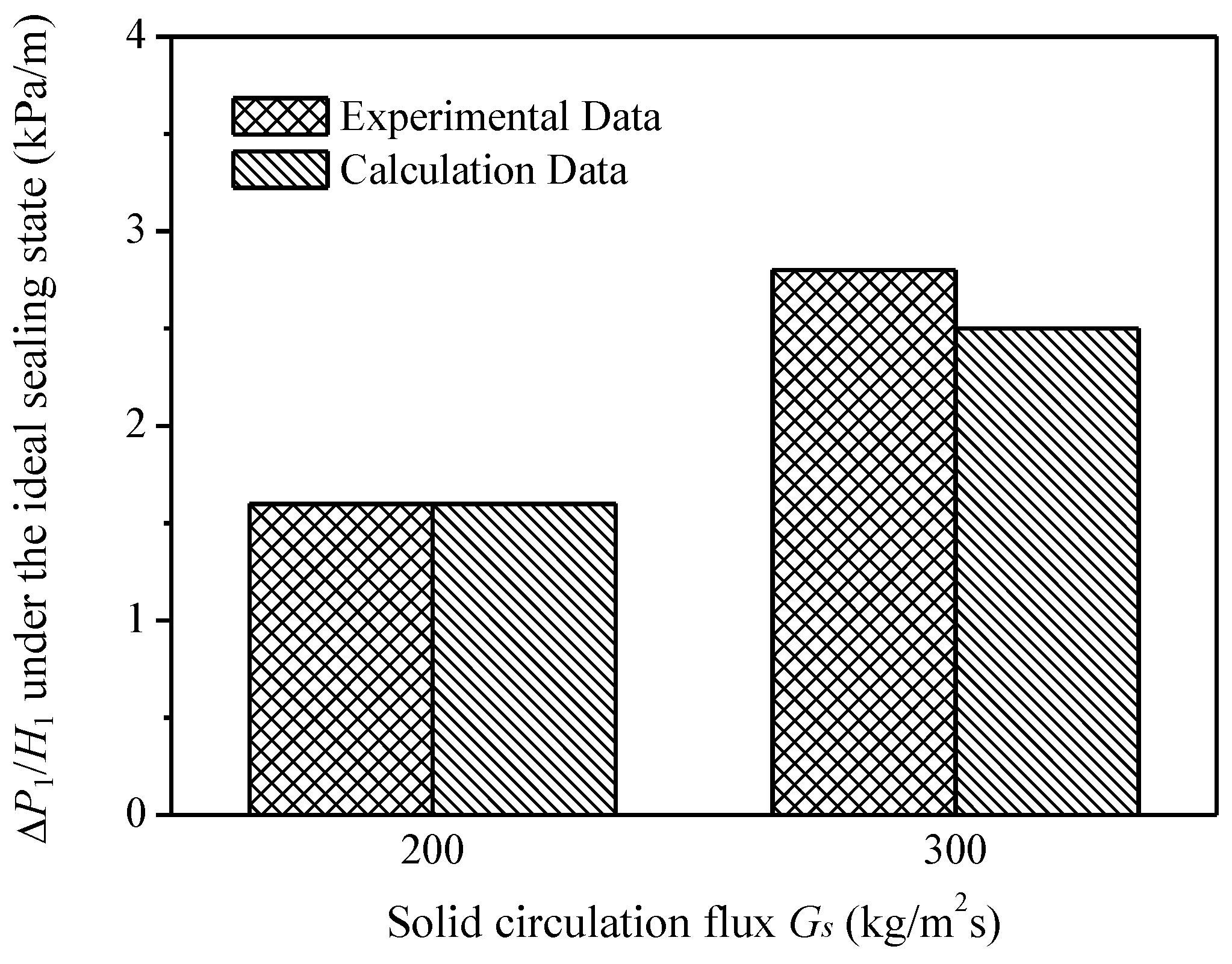
- The theoretical methodology for gas leakages and solid circulation was successfully applied to the condition design and operation of the cold system, achieving favorable gas–solid flow and circulation together with good control of gas leakages in the whole system.
- (4)
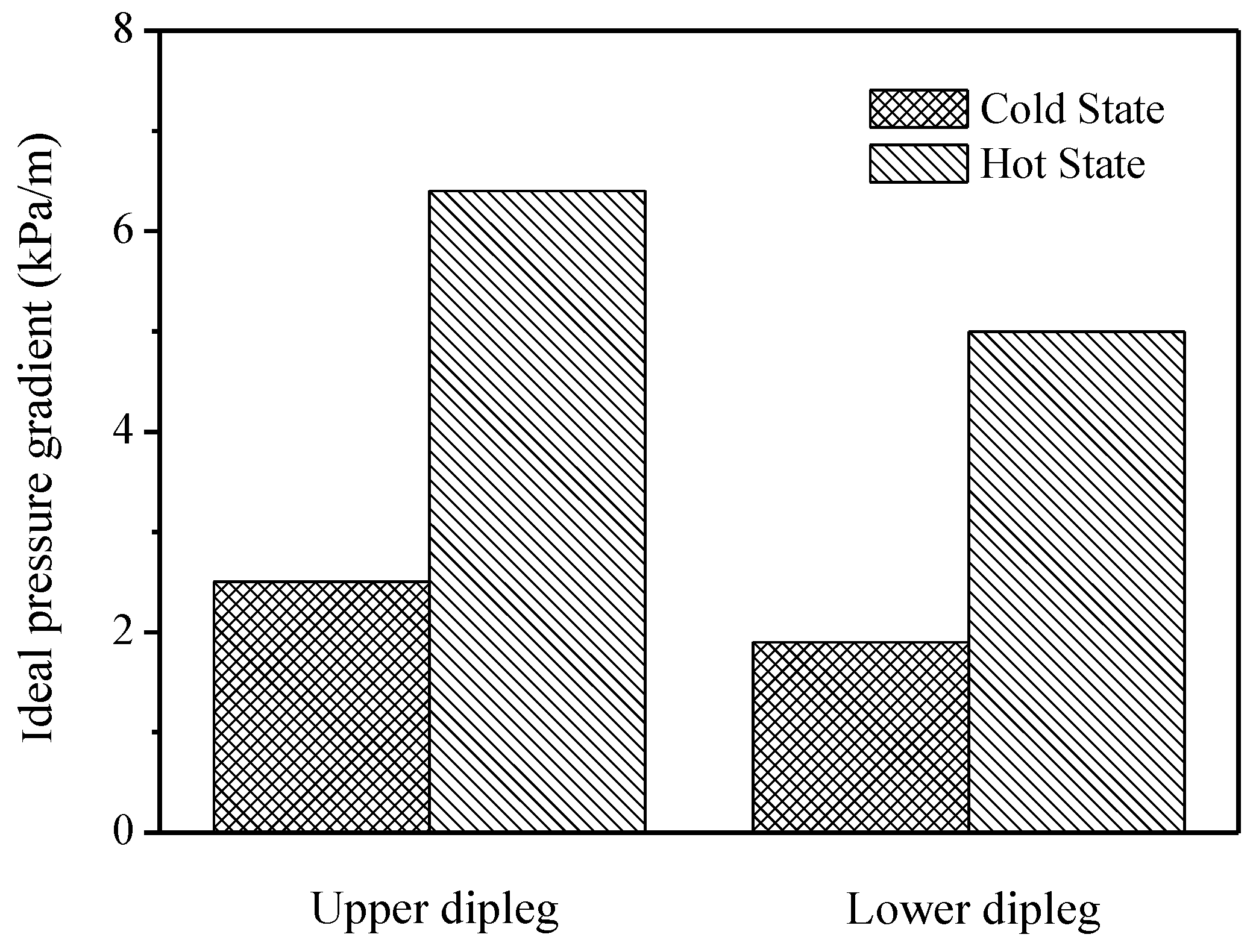
- The theoretical methodology was adopted to carry out a capability assessment of the high-flux CDCLC system under a hot state in terms of the restraint of gas leakages and the stability of solid circulation. The ideal pressure gradients under the hot state of 1243 K were about 2.6 times than those under the cold state, implying a lower requirement of sealing height in the hot state. However, on the other hand, the increase of the ideal pressure gradients also led to the approach of the optimal pressure gradients for gas leakages to the critical pressure gradients for circulation stability, which would increase the risk of circulation collapse during the operation process.
Author Contributions
Funding
Conflicts of Interest
Nomenclature
| Aud | sectional area of the upper downcomer (m2) |
| Af | sectional area of the upper FR (m2) |
| ds | mean diameter of the OC particles (mm) |
| Df | FR diameter (m) |
| Dud | upper downcomer diameter (m) |
| f1 | FR leakage ratio |
| f2 | AR leakage ratio |
| f3 | J-valve leakage ratio |
| fi | gas leakage ratio between the two reactors (i = 1 or 2) |
| g | acceleration due to gravity (9.8 m/s2) |
| gc | conversion coefficient (9.8 N/kg) |
| Gs | solid circulation flux (kg/m2·s) |
| H1 | solid-seal height of the upper dipleg of the AR (m) |
| H2 | solid-seal height of the lower dipleg of the AR (m) |
| ∆H | scale height in the upper dipleg of the AR (m) |
| Lld | side length of the lower downcomer (m) |
| Pb | pressure of the AR outlet (kPa) |
| Pc | pressure of the AR inlet (kPa) |
| Pd | top pressure of the lower dipleg of the AR (kPa) |
| Pi | pressure at the interface of the dense phase and dilute phase of the upper downcomer (kPa) |
| P11 | pressure at the underside of the separator (kPa) |
| P12 | pressure at the top position of the lower dipleg (kPa) |
| local pressure drop at two adjacent elevations of the FR (kPa) | |
| critical pressure gradient for circulation stability (kPa/m) | |
| ΔP1/H1 | upper pressure gradient of the AR (kPa/m) |
| upper pressure gradient of the AR under the ideal sealing state (kPa/m) | |
| transient upper pressure gradient of the AR (kPa/m) | |
| ΔP2/H2 | lower pressure gradient of the AR (kPa/m) |
| lower pressure gradient of the AR under the ideal sealing state (kPa/m) | |
| transient lower pressure gradient of the AR (kPa/m) | |
| Q1,sta | inlet air flow rate of the FR distributor (m3/h) |
| Q2,sta | fluidizing air flow rate of the J-valve (m3/h) |
| Q3,sta | aeration air flow rate of the J-valve (m3/h) |
| Q4,sta | inlet air flow rate of the AR (m3/h) |
| Qa,sta | outlet air flow rate of the FR (m3/h) |
| Qb,sta | outlet air flow rate of the AR (m3/h) |
| t | measured duration of the OC particles passing through the scale height (s) |
| T | operation temperature (K) |
| us | velocity of the OC particles in the upper dipleg (m/s) |
| Uf,sta | FR superficial gas velocity (m/s) |
| Us | solids velocity (m/s) |
| concentration of tracer gas 1 measured at the outlet of the separator (ppm) | |
| concentration of tracer gas 1 measured at the AR outlet (ppm) | |
| concentration of tracer gas 2 measured at the outlet of the separator (ppm) | |
| concentration of tracer gas 2 measured at the AR outlet (ppm) | |
| concentration of tracer gas 3 measured at the outlet of the separator (ppm) | |
| concentration of tracer gas 3 measured at the AR outlet (ppm) | |
| height difference between two adjacent elevations of the FR (m) | |
| slope of the linear fitting equation of FR leakage ratio | |
| slope of the linear fitting equation of AR leakage ratio | |
| slope of the linear fitting equation of J-valve leakage ratio | |
| dimensionless coefficient of the fitting equation of critical sealing gradient | |
| ε | void fraction in the downcomer |
| εs | cross-sectional average solids holdup in the FR |
| φs | sphere coefficient of the OC particles |
| ρb | bulk density of the OC particles (kg/m3) |
| ρg | density of air (kg/m3) |
| ρs | apparent density of the OC particles (kg/m3) |
| μg | dynamic viscosity of air (Pa·s) |
References
- Kim, H.R.; Wang, D.; Zeng, L.; Bayham, S.; Tong, A.; Chung, E.; Kathe, M.V.; Luo, S.; McGiveron, O.; Wang, A.; et al. Coal direct chemical looping combustion process: Design and operation of a 25-kWth sub-pilot unit. Fuel 2013, 108, 370–384. [Google Scholar] [CrossRef]
- Bayham, S.C.; Kim, H.R.; Wang, D.; Tong, A.; Zeng, L.; McGiveron, O.; Kathe, M.V.; Chung, E.; Wang, W.; Wang, A.; et al. Iron-based coal direct chemical looping combustion process: 200-h continuous operation of a 25-kWth subpilot unit. Energy Fuels 2013, 27, 1347–1356. [Google Scholar] [CrossRef]
- Berguerand, N.; Lyngfelt, A. Design and operation of a 10 kWth chemical-looping combustor for solid fuels-testing with South African coal. Fuel 2008, 87, 2713–2726. [Google Scholar] [CrossRef]
- Shen, L.H.; Wu, J.H.; Xiao, J. Experiments on chemical looping combustion of coal with a NiO based oxygen carrier. Combust. Flame 2009, 156, 721–728. [Google Scholar] [CrossRef]
- Xiao, R.; Chen, L.; Saha, C.; Zhang, S.; Bhattacharya, S. Pressurized chemical-looping combustion of coal using an iron ore as oxygen carrier in a pilot-scale unit. Int. J. Greenh. Gas Control 2012, 10, 363–373. [Google Scholar] [CrossRef]
- Abad, A.; Gayán, P.; de Diego, L.F.; García-Labiano, F.; Adánez, J. Fuel reactor modelling in chemical-looping combustion of coal: 1. Model formulation. Chem. Eng. Sci. 2013, 87, 277–293. [Google Scholar] [CrossRef]
- García-Labiano, F.; de Diego, L.F.; Gayán, P.; Abad, A.; Adánez, J. Fuel reactor modelling in chemical-looping combustion of coal: 2-simulation and optimization. Chem. Eng. Sci. 2013, 87, 173–182. [Google Scholar] [CrossRef]
- Wang, X.; Jin, B.; Zhang, Y.; Zhang, Y.; Liu, X. Three dimensional modeling of a coal-fired chemical looping combustion process in the circulating fluidized bed fuel reactor. Energy Fuels 2013, 27, 2173–2184. [Google Scholar] [CrossRef]
- Markström, P.; Linderholm, C.; Lyngfelt, A. Operation of a 100 kW chemical-looping combustor with Mexican petroleum coke and Cerrejón coal. Appl. Energy 2014, 113, 1830–1835. [Google Scholar] [CrossRef]
- Ströhle, J.; Orth, M.; Epple, B. Design and operation of a 1 MWth chemical looping plant. Appl. Energy 2014, 113, 1490–1495. [Google Scholar] [CrossRef]
- Thon, A.; Kramp, M.; Hartge, E.-U.; Heinrich, S.; Werther, J. Operational experience with a system of coupled fluidized beds for chemical looping combustion of solid fuels using ilmenite as oxygen carrier. Appl. Energy 2014, 118, 309–317. [Google Scholar] [CrossRef]
- Bayham, S.; McGiveron, O.; Tong, A.; Chung, E.; Kathe, M.; Wang, D.; Zeng, L.; Fan, L.S. Parametric and dynamic studies of an iron-based 25-kWth coal direct chemical looping unit using sub-bituminous coal. Appl. Energy 2015, 145, 354–363. [Google Scholar] [CrossRef]
- Wang, X.; Jin, B.; Liu, X.; Zhang, Y.; Liu, H. Experimental investigation on flow behaviors in a novel in situ gasification chemical looping combustion apparatus. Ind. Eng. Chem. Res. 2013, 52, 14208–14218. [Google Scholar] [CrossRef]
- Wang, X.; Jin, B.; Liu, H.; Wang, W.; Liu, X.; Zhang, Y. Optimization of in situ gasification chemical looping combustion through experimental investigations with a cold experimental system. Ind. Eng. Chem. Res. 2015, 54, 5749–5758. [Google Scholar] [CrossRef]
- Wang, X.; Jin, B.; Zhu, X.; Liu, H. Experimental evaluation of a novel 20 kWth in situ gasification chemical looping combustion unit with an iron ore as the oxygen carrier. Ind. Eng. Chem. Res. 2016, 55, 11775–11784. [Google Scholar] [CrossRef]
- Adánez, J.; Abad, A.; Perez-Vega, R.; Luis, F.; García-Labiano, F.; Gayán, P. Design and operation of a coal-fired 50 kWth chemical looping combustor. Energy Procedia 2014, 63, 63–72. [Google Scholar] [CrossRef]
- Ma, J.; Zhao, H.; Tian, X.; Wei, Y.; Rajendran, S.; Zhang, Y.; Bhattacharya, S.; Zheng, C. Chemical looping combustion of coal in a 5 kWth interconnected fluidized bed reactor using hematite as oxygen carrier. Appl. Energy 2015, 157, 304–313. [Google Scholar] [CrossRef]
- Su, M.; Zhao, H.; Ma, J. Computational fluid dynamics simulation for chemical looping combustion of coal in a dual circulation fluidized bed. Energy Convers. Manag. 2015, 105, 1–12. [Google Scholar] [CrossRef]
- Ohlemüller, P.; Alobaid, F.; Abad, A.; Adanez, J.; Ströhle, J.; Epple, B. Development and validation of a 1D process model with autothermal operation of a 1 MWth chemical looping pilot plant. Int. J. Greenh. Gas Control 2018, 73, 29–41. [Google Scholar] [CrossRef]
- Wang, X.; Liu, X.; Jin, B.; Wang, D. Hydrodynamic study of AR coupling effects on solid circulation and gas leakages in a high-flux in situ gasification chemical looping combustion system. Processes 2018, 6, 196. [Google Scholar] [CrossRef]
- Wang, X.; Jin, B.; Zhong, W.; Zhang, M.; Huang, Y.; Duan, F. Flow behaviors in a high-flux circulating fluidized bed. Int. J. Chem. React. Eng. 2008, 6, A79. [Google Scholar] [CrossRef]
- Issangya, A.S.; Bai, D.; Bi, H.T.; Lim, K.S.; Zhu, J.; Grace, J.R. Suspension densities in a high-density circulating fluidized bed riser. Chem. Eng. Sci. 1999, 54, 5451–5460. [Google Scholar] [CrossRef]
- Namkung, W.; Kim, S.W.; Kim, S.D. Flow regimes and axial pressure profiles in a circulating fluidized bed. Chem. Eng. J. 1999, 54, 245–252. [Google Scholar] [CrossRef]
- Li, Z.Q.; Wu, C.N.; Wei, F.; Jin, Y. Experimental study of high-density gas-solids flow in a new coupled circulating fluidized bed. Powder Technol. 2004, 139, 214–220. [Google Scholar] [CrossRef]
- Jing, S.; Li, H. Study on the flow of fine powders from hoppers connected to a moving-bed standpipe with negative pressure gradient. Powder Technol. 1999, 101, 266–278. [Google Scholar] [CrossRef]
- Nagashima, H.; Ishikura, T.; Ide, M. Flow characteristics of a small moving bed downcomer with an orifice under negative pressure gradient. Powder Technol. 2009, 192, 110–115. [Google Scholar] [CrossRef]
- Wang, J.; Bouma, J.H.; Dries, H. An experimental study of cyclone dipleg flow in fluidized catalytic cracking. Powder Technol. 2000, 112, 221–228. [Google Scholar] [CrossRef]
- Wang, Q.; Yang, H.; Wang, P.; Lu, J.; Liu, Q.; Zhang, H.; Wei, L.; Zhang, M. Application of CPFD method in the simulation of a circulating fluidized bed with a loop seal, part I—Determination of modeling parameters. Powder Technol. 2014, 253, 814–821. [Google Scholar] [CrossRef]
- Wang, Q.; Yang, H.; Wang, P.; Lu, J.; Liu, Q.; Zhang, H.; Wei, L.; Zhang, M. Application of CPFD method in the simulation of a circulating fluidized bed with a loop seal Part II—Investigation of solids circulation. Powder Technol. 2014, 253, 822–828. [Google Scholar] [CrossRef]
- Yin, S.; Jin, B.; Zhong, W.; Lu, Y.; Shao, Y.; Liu, H. Gas-solid flow behavior in a pressurized high-flux circulating fluidized bed riser. Chem. Eng. Commun. 2014, 201, 352–366. [Google Scholar] [CrossRef]
- Wang, Z.; Zhao, T.; Yao, J.; Liu, K.; Takei, M. Influence of particle size on the exit effect of a full-scale rolling circulating fluidized bed. Part. Sci. Technol. 2018, 36, 541–551. [Google Scholar] [CrossRef]
- Chang, G.; Yang, G.; Yang, S.; Li, S.; Li, H. Gas solid flow in a moving bed under negative pressure difference. J. Chem. Ind. Eng. 1980, 31, 229–240. [Google Scholar]
- Ergun, S. Fluid flow through packed columns. Chem. Eng. Prog. 1952, 48, 89–94. [Google Scholar]
- Leung, L.S.; Jones, P.J. Flow of gas—Solid mixtures in standpipes. A review. Powder Technol. 1978, 20, 145–160. [Google Scholar] [CrossRef]
- Ozahi, E.; Gundogdu, M.Y.; Carpinlioglu, M.Ö. A modification on Ergun’s correlation for use in cylindrical packed beds with non-spherical particles. Adv. Powder Technol. 2008, 19, 369–381. [Google Scholar] [CrossRef]


| Description | Value |
|---|---|
| Density of air ρg (kg/m3) | 1.29 |
| Dynamic viscosity of air μg (Pa·s) | 1.78 × 10⁻⁵ |
| Apparent density of the OC ρs (kg/m3) | 3015 |
| Void fraction in the downcomer ε (-) | 0.477 |
| Mean diameter of the OC ds (mm) | 0.43 |
| Sphere coefficient of the OC φs (-) | 0.7 |
| Diameter of the FR Df (m) | 0.06 |
| Diameter of the upper downcomer Dud (m) | 0.10 |
| Description | Parameter | Measured Value (%) | Calculation Value (%) | Relative Error (%) |
|---|---|---|---|---|
| ΔP1/H1 = 3.8 kPa/m | FR leakage ratio f1 | −0.1 | 0 | - |
| AR leakage ratio f2 | 2.5 | 2.9 | 14 | |
| ΔP2/H2 = 5.2 kPa/m | J-valve leakage ratio f3 | 15.2 | 14.2 | 7 |
| Description | Value |
|---|---|
| Temperature (K) | 1243 |
| Solid circulation flux Gs (kg/m2·s) | 300 |
| Gas dynamic viscosity under the hot state μg,hot (Pa·s) | 4.7 × 10⁻⁵ |
| Apparent density of the OC ρs (kg/m3) | 3015 |
| Void fraction in the downcomer ε (-) | 0.477 |
| Mean diameter of the OC ds (mm) | 0.43 |
| Sphere coefficient of the OC φs (-) | 0.7 |
| FR diameter Df (m) | 0.06 |
| Upper downcomer diameter Dud (m) | 0.10 |
| Side length of the lower downcomer Lld (m) | 0.10 |
© 2018 by the authors. Licensee MDPI, Basel, Switzerland. This article is an open access article distributed under the terms and conditions of the Creative Commons Attribution (CC BY) license (http://creativecommons.org/licenses/by/4.0/).
Share and Cite
Wang, X.; Liu, X.; Jin, Z.; Zhu, J.; Jin, B. Theoretical Methodology of a High-Flux Coal-Direct Chemical Looping Combustion System. Processes 2018, 6, 251. https://doi.org/10.3390/pr6120251
Wang X, Liu X, Jin Z, Zhu J, Jin B. Theoretical Methodology of a High-Flux Coal-Direct Chemical Looping Combustion System. Processes. 2018; 6(12):251. https://doi.org/10.3390/pr6120251
Chicago/Turabian StyleWang, Xiaojia, Xianli Liu, Zhaoyang Jin, Jiewen Zhu, and Baosheng Jin. 2018. "Theoretical Methodology of a High-Flux Coal-Direct Chemical Looping Combustion System" Processes 6, no. 12: 251. https://doi.org/10.3390/pr6120251
APA StyleWang, X., Liu, X., Jin, Z., Zhu, J., & Jin, B. (2018). Theoretical Methodology of a High-Flux Coal-Direct Chemical Looping Combustion System. Processes, 6(12), 251. https://doi.org/10.3390/pr6120251