Abstract
Mineral calcination worldwide accounts for some 5–10% of all anthropogenic carbon dioxide (CO2) emissions per year. Roughly half of the CO2 released results from burning fossil fuels for heat generation, while the other half is a product of the calcination reaction itself. Traditionally, the fuel combustion process and the calcination reaction take place together to enhance heat transfer. Systems have been proposed that separate fuel combustion and calcination to allow for the sequestration of pure CO2 from the calcination reaction for later storage/use and capture of the combustion gases. This work presents a new tube-in-tube helical system for the calcination of minerals that can use different heat transfer fluids (HTFs), employed or foreseen in concentrated solar power (CSP) plants. The system is labeled ‘flameless’ since the HTF can be heated by other means than burning fossil fuels. If CSP or high-temperature nuclear reactors are used, direct CO2 emissions can be divided in half. The technical feasibility of the system has been accessed with a brief parametric study here. The results suggest that the introduced system is technically feasible given the parameters (total heat transfer coefficients, mass- and volume flows, outer tube friction factors, and –Nusselt numbers) that are examined. Further experimental work will be required to better understand the performance of the tube-in-tube helical system for the flameless calcination of minerals.
1. Introduction
Today, minerals are predominantly calcined using fossil fuel-fired vertical kilns that have replaced earlier, less efficient, horizontal rotary kilns. During the calcination process carbon dioxide (CO2) is released as a result of power generation (burning fossil fuels) and the calcination reaction itself that is provided below for limestone (Latin: calcinare = to burn lime).
Worrel et al. [1] first estimated that the cement industry, the largest calcination industry, contributes to about 5% of annual global anthropogenic CO2 emissions. Ali et al. [2] more recently concluded that in the cement industry roughly half of the emissions result from power production and half of the emissions originate from the calcination reaction itself. Work on CO2 reduction during calcination has focused on carbon capture [3,4,5,6,7,8] and using different energy sources, such as concentrated solar power (CSP), which may provide the high temperatures needed for the traditional calcination process. Solar calcination experiments were conducted by Flamant et al. [9,10], Licht et al. [11], Meier et al. [12,13,14,15], as well as Salman and Kraishi [16]. Of particular interest for this study is work by Sceats et al. [17] who proposed an externally heated closed coil design of which a cross-section is schematically shown in Figure 1 (top). The pitch of the helix is equal to the outer diameter of the reactor tube, so that a closed coil is formed. Fuel combustion, electrical heating, or a heat transfer fluid (HTF) are foreseen in the externally heated closed coil design. If a HTF is used, a tube-in-tube design may be beneficial in a way that the area for heat transfer can be doubled as depicted in Figure 1 (bottom).
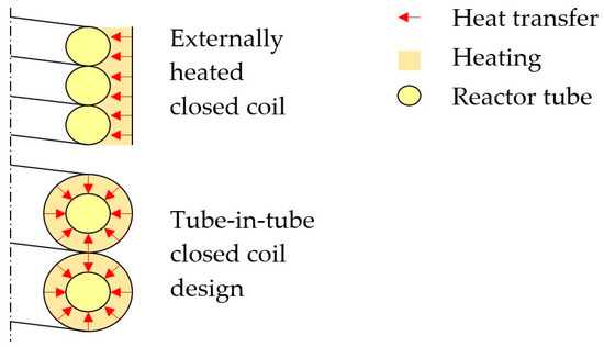
Figure 1.
Simplified cross section of the externally heated closed helical coil design (top) and the tube-in-tube closed helical coil design proposed here (bottom).
Calcination systems that use CSP-heated HTFs to transfer heat to a mineral feed reach lower calcination temperatures than systems that directly concentrate solar radiation on a small volume of the mineral feed material. The later was for instance achieved by the multitube rotary reactor design from Meier et al. [13,15] for the calcination of lime. CSP-systems with HTFs may, however, realize larger mineral throughputs (at lower temperatures) than systems without HTFs, as they can heat larger volumes of the feed material. In addition, other process heat sources, such as fossil fuel sources for initial testing or high temperature reactors (HTRs) [18,19] can be employed. Indirect-fired rotary kilns are well known in industry [20] and indirectly heated calciners, as proposed by Abanades et al. [21], are presently investigated using heat-pipe-designs [22,23,24,25]. In addition, Moon et al. [26] developed a multistep process for CO2 capture consisting of double fluidized-bed tube-in-tube reactors. Tube-in-tube heat exchangers are used for heating, ventilation, and air conditioning (HVAC), cryogenic processes, waste heat recovery, space applications, as well as chemical and food processing. The devices provide a large surface area per unit volume and excellent heat transfer characteristics, if compared to shell and tube heat exchangers, due to the secondary flow motion induced by the curvature [27]. Combining indirect calciners with tube-in-tube heat exchangers for mineral calcination is not cost-competitive today with CSP and HTRs [28]. It may still be worthwhile to look into this technology though, as it can become cost-competitive in the future when expenses for CSP/HTR plants further decrease, as presently anticipated [28]. In addition, flameless calcination using CSP/HTRs has the potential to cut direct CO2 emissions in half and can enhance energy security in regions dependent on fossil fuel imports.
The tube-in-tube helical system for mineral calcination is schematically shown in Figure 2. In the system, the mineral feed is finely ground, mixed with superheated steam and inserted with an injector (red) at the top of the helical reactor tube (yellow). On its way, through the inside of the helix, the mineral feed is preheated by rising exhaustion gases. The calcination reaction takes place while the powder-steam-mix travels downwards through the tubular reactor. At the bottom, CO2 and calcined granules separate. Pure CO2 leaves the reactor at the top where it can be captured. The product leaves the reactor at the bottom. The calcinated product could be sent to another, similar, calcination unit if further heat treatment is required. One calcination unit has a mineral throughput of approximately 1.45 kg/s and operates at reactor tube wall temperatures ranging from 200 to 960 °C. The design takes advantage of the catalytic effect superheated steam has on the calcination reaction. MacIntire and Stansel [29] conducted experiments to reduce temperatures during limestone calcination and reactive fertilizer production of dolomite. It was shown that the required calcination temperature for limestone and dolomite could be significantly reduced in the presence of superheated steam. Donat et al. [30], Li et al. [31] and Liu et al. [32] analyzed the catalytic effect of steam on CaO, which is relevant for cyclic CO2 capture. Zarghami et al. [33] describe the catalytic effect of steam on dolomite decomposition for CO2 capture. Sceats et al. [17] conducted tests with batches of 0.2–2.0 kg finely ground (125 microns) magnesite ore (97% MgCO3). It was confirmed that the residence time, as well as the required calcination temperature, can be significantly reduced (to a few seconds and <500 °C) if the material is finely ground and superheated steam (also <500 °C) is present.
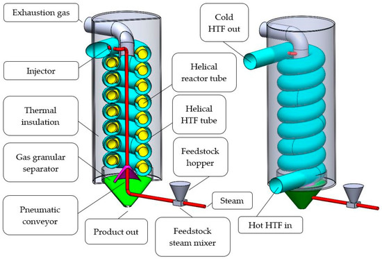
Figure 2.
Isometric cut view (left) and isometric view (right) of one segment of the proposed tube-in-tube helical system for mineral calcination.
In the tube-in-tube helical design, the product stream is placed in the inner tube to avoid clocking, as caused by stabilizing elements, which need to be inserted into the outer tube to fix the position of the inner reactor tube. While even small supporting inserts in the outer tube, may hinder a product stream, they have a beneficial effect on the chosen configuration in a way that the turbulence in the HTF is increased. Increased turbulence in the HTF results in a greater heat transfer from the HTF to the mineral feed.
The objectives of this work is to present a preliminary design of the tube-in-tube helical system for flameless calcination of minerals. Based on the required heat for mineral calcination at the outer wall of the inner tube provided by Sceats et al. [17], a parametric study considering different HTFs is offered. The parametric study is not complete and cannot substitute experimental work but provides insights into the technical feasibility of the proposed system. In the parametric study, the outer surface of the angular tube is assumed to be well insulated (adiabatic).
2. Methodology
Designing a tube-in-tube helical heat exchanger requires knowledge of the heat transfer coefficients for both the inner and the outer tube. Heat transfer rates of the gas-solid multiphase system consisting of a laminar (Re ≈ 200) granular flow and a turbulent (Re ≈ 3 × 10⁵) gas flow are dependent on a variety of factors (grain size, steam to grain ratio, steam feed rate, etc.) that need to be adjusted for different feed materials based on the feed material compositions. In addition, CO2 is produced while the material travels through the reactor tube in a downward direction so that the thermal properties of the gas mixture, as well as the thermal properties of the granules, are subject to change depending on the degree of calcination. Encapsulated impurities, such as organic materials, often different even within one ore body may affect the heat required for the calcination process in one way or another [34]. What is known is that the calcination temperature that needs to be reached, as well as the reaction enthalpy of pure material, so that based on these data it is possible to conduct a parametric study of the tube-in-tube helical calcination system. Sceats et al. [17] proposed three different temperature ranges depicted in Table 1.

Table 1.
Temperature ranges for different calcination processes proposed by Sceats et al. [17].
In this study, we consider the medium temperature range (500–650 °C). In the medium temperature range commercial, inexpensive [35] solar salt (0.6 NaNO3 + 0.4 KNO3) can be used as HTF and stainless steel that shows adequate corrosion resistance towards solar salt [36,37] can be used as a structural material. Present solar power towers using solar salt can offer bulk HTF temperatures as high as 565 °C [38]. Higher HTF temperatures can be realized using different HTFs [38,39,40,41,42,43]. In the medium temperature range dolomite (CaCO3) and magnesite (MgCO3) can be calcined.
2.1. Heat Transfer
The required heat rate is given by Sceats et al. [17] in Equation (2). To account for the surrounding outer tube, the pitch was increased from 0.3 m to 0.5 m, and the coil diameter was increased from 0.76 m to 0.96 m. With these changes, the number of revolutions reduces while remaining the same length of the reactor tube.
This relationship may be simplified assuming that the temperature difference between the feed material and the steam are negligible. This is realistic since feed material and steam are mixed in the riser tube that leads to the injector.
In both of the equations α describes the degree of the reaction. α depends on the degree of calcination (96–98% is envisaged) and the residence time.
Wang and Thompson [44], as well as Beruto and Searcy [45], determined the activation energy of calcite to be as high as 197 kJ/mol and 205 kJ/mol. Sceats et al. [17] subsequently estimated the power that was required for the calcination reaction to being 2.6 MW for 1.45 kg mineral feed per second per calcination unit employed. Olszak-Humienik and Jablonski [46] determined a very similar activation energy for dolomite (205.60 kJ/mol) so that the previously estimated required heat is used here as well. In the tube-in-tube helical system, the heat is provided by a HTF flowing in the annular tube surrounding the inner reactor tube. The entire outer surface of the inner tube (neglecting baffles or stabilizers to hold the inner tube) is available for heat transfer. Since the pitch had to be enlarged for the tube-in-tube design to accommodate for the annular tube the geometries have changed. For the sake of brevity, the outer surface area proposed by Sceats et al. [17] 25 m2 is used here as well (slightly reducing the length of the tube could for instance account for the increased pitch and coil diameter).
2.2. Outer Tube Mass and Volume Flows
The rate equation for heat exchangers [47]:
can be used to relate the true (effective) mean temperature difference of the two fluids ∆Tm to the total heat coefficient of the system. More than one helical segment may be employed, and different heights are possible. The rate equation can further be expressed with the mass flow and heat capacity.
2.3. Outer Tube Friction Factors
The friction factors in the annular tube can be determined via the Reynolds number. The friction factor is dependent on the Reynolds number:
and the friction coefficients of the two walls. Friction coefficients of the walls were not further considered here. The hydraulic diameter dh depends on the inner diameter of the outer tube and the outer diameter of the inner tube.
The friction factor in helical tubes is usually determined by determining the friction factor for a straight tube and then adding a factor that accounts for the secondary flow as a result of the curvature. Correlations from Mishra and Gupta [48], Ito [49], and White [50], as shown in Table 2, were used here to determine the friction factor in the outer helical tube for solar salt and the given geometry. Results were obtained using Re* for annular ducts as defined by Gnielinski [51,52,53]:
Table 2.
Friction factor correlations used in this work.
For the friction factor in annular ducts Gnielinski suggests using Konakovs [54] correlation for turbulent flow that is also provided in Table 2. Additional friction factor correlations not considered in this work and not listed in Table 2 are for instance provided by El-Genk and Schriener [55], Ghobadi and Muzychka [56], Huminic and Huminic [57] as well as Spedding et al. [58].
2.4. Outer Tube Friction Factors
The outer tube Nusselt numbers were determined using the correlations provided by Mandal and Nigam [59], Kumar et al. [60], Guo et al. [61], Rogers, and Mayhew [62], as well as El-Genk and Schriener [55]. The used correlations are provided in Table 3.
Table 3.
Correlations used to determine the outer Nusselt number.
3. Results and Discussion
3.1. Total Heat Transfer Coefficient
Using the rate equation (Equation (5)), the total heat transfer coefficient can be expressed over the mean temperature difference of the bulk mineral-steam mix in the inner tube and the HTF in the outer tube. Figure 3 shows the mean temperature difference over the total heat transfer coefficient that needs to be met to reach the power required for one segment (A = 25 m2) and two segments (A = 50 m2).
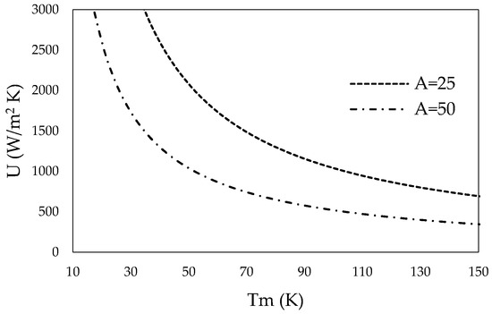
Figure 3.
Total heat transfer coefficient for one segment (A = 25 m2) and two segments (A = 50 m2) over the mean temperature difference.
CSP using solar salt can deliver HTFs at a bulk temperature of 565 °C, while mineral calcination may take place at 500 °C reactor tube inner wall temperature. Thus, the mean temperature difference is around 65 °C. Roetzel and Spang [63] provide typical values of overall heat transfer coefficients for various heat exchanger designs and fluids. Required heat transfer coefficients for one (A = 25 m2) or two segments (A = 50 m2) of the tube-in-tube helical system show realistic values.
Larger temperature differences may be reached by further heating the HTF using commercial electric heaters. Solar salt can be safely used at temperatures up to 600 °C. A brief list of other HTFs and their operating temperature ranges is provided in Table 4. Material properties were taken from Serrano-López et al. [64], as well as Boerema et al. [65], and were adjusted for different temperatures as recommended by the aforementioned authors. Additionally, the design can be changed in a way that hot HTF is inserted into the HTF-stream at different heights so that the HTF’s average temperatures increases.
Table 4.
Heat transfer fluids (HTFs) considered in this study.
3.2. Outer Tube Mass and Volume Flows
The rate equation (Equation (5)) can further be expressed using the mass flow and heat capacity of solar salt and other HTFs (Equation (6)). Figure 4 shows the required HTF mass flow (left) and the required HTF volume flow (right) over the HTFs inlet- and outlet temperature difference for various HTFs. The density and heat capacity of the HTFs are dependent on temperature. The arithmetic mean temperature and thermal characteristics of the HTFs, as suggested by Serrano-López et al. [64] and Boerema et al. [65], were taken for these calculations.
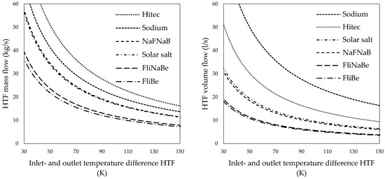
Figure 4.
Heat transfer fluid mass flows (left) and volume flows (right) of various heat transfer salts over the inlet- and outlet temperature difference of the outer tube.
Pumps that can provide the required molten salt mass flow at elevated temperatures are available from past and present molten salt reactor operations and experiments. Smith [66] describes the design and operation of pumps designed for the molten salt reactor experiment in the United States (U.S.) In addition, some commercial solar power towers, such as the Gemasolar plant [67,68,69] in Spain, use solar salt and large solar salt pumping equipment. Solar salt was the natural choice for this study since it is already in use at different CSP-plants and is relatively inexpensive. Figure 4 reveals that the HTF mass- and volume flow, could, however, be significantly reduced if FliNaBe or FliBe would be used as HTF instead of solar salt.
3.3. Outer Tube Friction Factors
The outer tube friction factor has been calculated for solar salt using the expressions, as provided in Table 2. Results are shown in Figure 5 (left) over the respective outer tube Dean numbers. The obtained results were compared to results for a straight tube and an angular duct using Konakov’s [54] equation as suggested by Gnielinski [51,53].
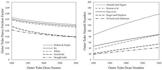
Figure 5.
Friction factor (left) and Nusselt number (right) over Dean numbers of the outer tube for solar salt.
Stabilizing elements, such as baffles, which may be introduced into the outer tube to enhance turbulence and thus heat transfer can further increase the friction factor as experiments from Kumar et al. [70], as well as Mandal and Nigam [59], showed.
The friction factor can be used to estimate the pressure drop for different HTFs. Counter-flow was the natural choice over parallel-flow since the heat transfer is greatly improved this way. Using parallel flow, i.e., inserting the HTF at the top may, however, be a valid alternative to reduce the required pumping power. Given that a solar tower is used to heat the HTF this may further reduce construction material.
3.4. Outer Tube Nusselt Numbers
Outer tube Nusselt numbers were determined using the expressions provided in Table 3 and are depicted in Figure 5 (right). Results vary significantly. Values obtained using the correlation from Mandal and Nigam [59] are considerably higher than the results for helically coiled tubes provided by Kumar et al. [60], Guo et al. [61], Roger and Mayhew [62] as well as El-Genk and Schriener [55]. Mandal and Nigam explain this with baffles that are inserted into the outer tube of their tube-in-tube heat exchanger. The baffles cause additional turbulence and thus increase heat transfer. This phenomenon was previously described for the same heat exchanger by Kumar et al. [60,70] and is reasonable.
4. Conclusions
In this study, a tube-in-tube helical system for flameless calcination of minerals is introduced. The required total heat transfer coefficients for a single unit and two units in a row were determined for different HTF in- and outlet temperatures. The required mass- and volume flows of different HTFs were determined. Solar salt is the natural choice over other HTFs that show better heat transfer characteristics since solar salt is already in use at a number of facilities and is relatively inexpensive. The outer tube Darcy friction factors, as well as the outer tube Nusselt numbers, were identified over an expected range of Dean numbers for solar salt using numerically and experimentally derived expressions that were available from previous studies. The introduced flameless system can provide the required heat input with all of the examined parameters showing realistic values. Consequently, it is found that the introduced tube-in-tube helical system for mineral calcination is technically feasible. Experimental work will, however, be required to further understand the performance of the tube-in-tube helical system for flameless mineral calcination introduced here.
Acknowledgments
The authors sincerely thank the editorial office of Processes for the invitation to contribute to this journal and waiving the article processing charge. This research was made possible by DAAD and CSC. The sponsoring agencies may not have endorsed the views expressed here. Any remaining inconsistencies or omissions are the authors’ alone.
Author Contributions
All authors contributed to this work. N.H. drafted the manuscript, which was edited and approved by Y.Z. and H.-J.A. All authors read and approved the final manuscript.
Conflicts of Interest
The authors declare no conflict of interest.
Nomenclature
| A | area (m2) |
| d | tube diameter (m) |
| D | Coil diameter (m) |
| fD | Darcy friction factor |
| Nu | Nusselt number |
| q | heat flow (W) |
| t | time (s) |
| U | Overall heat transfer coefficient (W/(m2K)) |
| Y | degree of calcination |
| cp | heat capacity (J/K) |
| dh | hydraulic diameter (m2) |
| De | Dean number (Re ) |
| mass flow (kg/s) | |
| Pr | Prandtl Number |
| Re | Reynolds number |
| T | Temperature (K) |
| v | speed (m/s) |
Greek symbols
| degree of reaction | |
| η | dynamic viscosity (Ps s) |
| difference operator | |
| density (kg/m3) |
References
- Worrell, E.; Price, L.; Martin, N.; Hendriks, C.; Meida, L.O. Carbon Dioxide Emission from the Global Cement Industry. Annu. Rev. Energy Environ. 2001, 26, 303–329. [Google Scholar] [CrossRef]
- Ali, M.B.; Saidur, R.; Hossain, M.S. A review on emission analysis in cement industries. Renew. Sustain. Energy Rev. 2011, 15, 2252–2261. [Google Scholar] [CrossRef]
- Wang, Q.; Luo, J.; Zhong, Z.; Borgna, A. CO2 capture by solid adsorbents and their applications: Current status and new trends. Energy Environ. Sci. 2011, 4, 42–55. [Google Scholar] [CrossRef]
- Yu, C.H.; Huang, C.H.; Tan, C.S. A review of CO2 capture by absorption and adsorption. Aerosol Air Qual. Res. 2012, 12, 745–769. [Google Scholar] [CrossRef]
- Leung, D.Y.C.; Caramanna, G.; Maroto-Valer, M.M. An overview of current status of carbon dioxide capture and storage technologies. Renew. Sustain. Energy Rev. 2014, 39, 426–443. [Google Scholar] [CrossRef]
- Atsonios, K.; Grammelis, P.; Antiohos, S.K.; Nikolopoulos, N.; Kakaras, E. Integration of calcium looping technology in existing cement plant for CO2 capture: Process modeling and technical considerations. Fuel 2015, 153, 210–223. [Google Scholar] [CrossRef]
- Reich, L.; Yue, L.; Bader, R.; Lipiński, W. Towards solar thermochemical carbon dioxide capture via calcium oxide looping: A review. Aerosol Air Qual. Res. 2014, 14, 500–514. [Google Scholar] [CrossRef]
- Benhelal, E.; Zahedi, G.; Shamsaei, E.; Bahadori, A. Global strategies and potentials to curb CO2 emissions in cement industry. J. Clean. Prod. 2013, 51, 142–161. [Google Scholar] [CrossRef]
- Flamant, G.; Hernandez, D.; Bonet, C.; Traverse, J.P. Experimental aspects of the thermochemical conversion of solar energy; Decarbonation of CaCO3. Sol. Energy 1980, 24, 385–395. [Google Scholar] [CrossRef]
- Flamant, G.; Gauthier, D.; Boudhari, C.; Flitris, Y. A 50 kW fluidized bed high temperature solar receiver: Heat transfer analysis. J. Sol. Energy Eng. 1988, 110, 313–320. [Google Scholar] [CrossRef]
- Licht, S.; Wu, H.; Hettige, C.; Wang, B.; Asercion, J.; Lau, J.; Stuart, J. STEP cement: Solar Thermal Electrochemical Production of CaO without CO2 emission. Chem. Commun. 2012, 48, 6019–6021. [Google Scholar] [CrossRef] [PubMed]
- Meier, A.; Bonaldi, E.; Cella, G.M.; Lipinski, W.; Wuillemin, D. Solar chemical reactor technology for industrial production of lime. Sol. Energy 2006, 80, 1355–1362. [Google Scholar] [CrossRef]
- Meier, A.; Bonaldi, E.; Cella, G.M.; Lipinski, W.; Wuillemin, D.; Palumbo, R. Design and experimental investigation of a horizontal rotary reactor for the solar thermal production of lime. Energy 2004, 29, 811–821. [Google Scholar] [CrossRef]
- Meier, A.; Gremaud, N.; Steinfeld, A. Economic evaluation of the industrial solar production of lime. Energy Convers. Manag. 2005, 46, 905–926. [Google Scholar] [CrossRef]
- Meier, A.; Bonaldi, E.; Cella, G.M.; Lipinski, W. Multitube Rotary Kiln for the Industrial Solar Production of Lime. J. Sol. Energy Eng. 2005, 127, 386–395. [Google Scholar] [CrossRef]
- Salman, O.A.; Kraishi, N. Thermal decomposition of limestone and gypsum by solar energy. Sol. Energy 1988, 41, 305–308. [Google Scholar] [CrossRef]
- Sceats, M.G.; Horley, C.J.; Richardson, P. System and Method for the Calcination of Minerals. U.S. Patent US 8,807,993, 19 August 2014. [Google Scholar]
- Haneklaus, N.; Reitsma, F.; Tulsidas, H. High Temperature Reactors for a new IAEA Coordinated Research Project on energy neutral mineral development processes. Nucl. Eng. Des. 2016, 306, 198–202. [Google Scholar] [CrossRef]
- Fütterer, M.A.; Li, F.; Sink, C.; de Groot, S.; Pouchon, M.; Kim, Y.W.; Carré, F.; Tachibana, Y. Status of the very high temperature reactor system. Prog. Nucl. Energy 2014, 77, 266–281. [Google Scholar] [CrossRef]
- FEECO. The Rotary Kiln Handbook; FEECO International Inc.: Green Bay, WI, USA, 2017. [Google Scholar]
- Abanades, J.C.; Anthony, E.J.; Wang, J.; Oakey, J.E. Fluidized Bed Combustion Systems Integrating CO2 Capture with CaO. Environ. Sci. Technol. 2005, 39, 2861–2866. [Google Scholar] [CrossRef] [PubMed]
- Höftberger, D.; Karl, J. Self-Fluidization in an Indirectly Heated Calciner. Chem. Eng. Technol. 2013, 36, 1533–1538. [Google Scholar] [CrossRef]
- Höftberger, D.; Karl, J. The Indirectly Heated Carbonate Looping Process for CO2 Capture—A Concept With Heat Pipe Heat Exchanger. J. Energy Ressour. Technol. 2016, 138, 042211. [Google Scholar] [CrossRef]
- Junk, M.; Reitz, M.; Ströhle, J.; Epple, B. Technical and Economical Assessment of the Indirectly Heated Carbonate Looping Process. J. Energy Ressour. Technol. 2016, 138, 042210. [Google Scholar] [CrossRef]
- Reitz, M.; Junk, M.; Ströhle, J.; Epple, B. Design and operation of a 300 kWth indirectly heated carbonate looping pilot plant. Int. J. Greenh. Gas Control 2016, 54, 272–281. [Google Scholar] [CrossRef]
- Moon, H.; Yoo, H.; Seo, H.; Park, Y.-K.; Cho, H.H. Thermal design of heat-exchangeable reactors using a dry-sorbent CO2 capture multi-step process. Energy 2015, 84, 704–713. [Google Scholar] [CrossRef]
- Aly, W.I.A. Numerical study on turbulent heat transfer and pressure drop of nanofluid in coiled tube-in-tube heat exchangers. Energy Convers. Manag. 2014, 79, 304–316. [Google Scholar] [CrossRef]
- Haneklaus, N.; Schröders, S.; Zheng, Y.; Allelein, H.-J. Economic evaluation of flameless phosphate rock calcination using concentrated solar power and high temperature reactors. Energy 2017, 140, 1148–1157. [Google Scholar] [CrossRef]
- Maclntire, W.H.; Stansel, T.B. Steam Catalysis in Calcinations of Dolomite and Limestone Fines. Ind. Eng. Chem. 1953, 45, 1548–1555. [Google Scholar] [CrossRef]
- Donat, F.; Florin, N.H.; Anthony, E.J.; Fennell, P.S. Influence of high-temperature steam on the reactivity of CaO sorbent for CO2 capture. Environ. Sci. Technol. 2012, 46, 1262–1269. [Google Scholar] [CrossRef] [PubMed]
- Li, Z.H.; Wang, Y.; Xu, K.; Yang, J.Z.; Niu, S.B.; Yao, H. Effect of steam on CaO regeneration, carbonation and hydration reactions for CO2 capture. Fuel Process. Technol. 2016, 151, 101–106. [Google Scholar] [CrossRef]
- Liu, W.; An, H.; Qin, C.; Yin, J.; Wang, G.; Feng, B.; Xu, M. Performance enhancement of calcium oxide sorbents for cyclic CO2 capture—A review. Energy Fuels 2012, 26, 2751–2767. [Google Scholar] [CrossRef]
- Zarghami, S.; Ghadirian, E.; Arastoopour, H.; Abbasian, J. Effect of Steam on Partial Decomposition of Dolomite. Ind. Eng. Chem. Res. 2015, 54, 5398–5406. [Google Scholar] [CrossRef]
- Abouzeid, A.Z.M. Physical and thermal treatment of phosphate ores—An overview. Int. J. Miner. Process. 2008, 85, 59–84. [Google Scholar] [CrossRef]
- Kearney, D.; Herrmann, U.; Nava, P.; Kelly, B.; Mahoney, R.; Pacheco, J.; Cable, R.; Potrovitza, N.; Blake, D.; Price, H. Assessment of a Molten Salt Heat Transfer Fluid in a Parabolic Trough Solar Field. J. Sol. Energy Eng. 2003, 125, 170–176. [Google Scholar] [CrossRef]
- Goods, S.H.; Bradshaw, R.W. Corrosion of stainless steels and carbon steel by molten mixtures of commercial nitrate salts. J. Mater. Eng. Perform. 2004, 13, 78–87. [Google Scholar] [CrossRef]
- McConohy, G.; Kruizenga, A. Molten nitrate salts at 600 and 680 °C: Thermophysical property changes and corrosion of high-temperature nickel alloys. Sol. Energy 2014, 103, 242–252. [Google Scholar] [CrossRef]
- Zhang, H.L.; Baeyens, J.; Degrève, J.; Cacères, G. Concentrated solar power plants: Review and design methodology. Renew. Sustain. Energy Rev. 2013, 22, 466–481. [Google Scholar] [CrossRef]
- Kolb, G.; Ho, C.; Mancini, T.; Gary, J. Power Tower Technology Roadmap and Cost Reduction Plan; SAND2011-2419; Sandia National Laboratories: Albuquerque, NM, USA, 2011. [CrossRef]
- Romero, M.; Steinfeld, A. Concentrating solar thermal power and thermochemical fuels. Energy Environ. Sci. 2012, 5, 9234–9245. [Google Scholar] [CrossRef]
- Forsberg, C.W.; Peterson, P.F.; Zhao, H. High-Temperature Liquid-Fluoride-Salt Closed-Brayton-Cycle Solar Power Towers. J. Sol. Energy Eng. 2007, 129, 141–146. [Google Scholar] [CrossRef]
- Barlev, D.; Vidu, R.; Stroeve, P. Innovation in concentrated solar power. Sol. Energy Mater. Sol. Cells 2011, 95, 2703–2725. [Google Scholar] [CrossRef]
- Vignarooban, K.; Xu, X.; Arvay, A.; Hsu, K.; Kannan, A.M. Heat transfer fluids for concentrating solar power systems—A review. Appl. Energy 2015, 146, 383–396. [Google Scholar] [CrossRef]
- Wang, Y.; Thomson, W.J. The Effects of Steam and Carbon-Dioxide on Calcite Decomposition Using Dynamic X-Ray-Diffraction. Chem. Eng. Sci. 1995, 50, 1373–1382. [Google Scholar] [CrossRef]
- Beruto, D.; Searcy, A.W. Use of the Langmuir method for kinetic studies of decomposition reactions: Calcite (CaCO3). J. Chem. Soc. Faraday Trans. 1974, 70, 2145–2153. [Google Scholar] [CrossRef]
- Olszak-Humienik, M.; Jablonski, M. Thermal behavior of natural dolomite. J. Therm. Anal. Calorim. 2015, 119, 2239–2248. [Google Scholar] [CrossRef]
- Shah, R.K.; Sekulic, D.P. Fundamentals of Heat Exchanger Design; John Wiley & Sons, Inc.: Hoboken, NJ, USA, 2003. [Google Scholar] [CrossRef]
- Mishra, P.; Gupta, S.N. Momentum Transfer in Curved Pipes. 1. Newtonian Fluids. Ind. Eng. Chem. Process. Des. Dev. 1979, 18, 130–137. [Google Scholar] [CrossRef]
- Ito, H. Friction factors for turbulent flow in curved pipes. J. Basic Eng. 1959, 81, 123–134. [Google Scholar]
- White, C.M. Friction factor and its relation to heat transfer. Trans. Inst. Chem. Eng. 1932, 18, 66–86. [Google Scholar]
- Gnielinski, V. Heat Transfer Coefficients for Turbulent Flow in Concentric Annular Ducts. Heat Transf. Eng. 2009, 30, 431–436. [Google Scholar] [CrossRef]
- Gnielinski, V. Turbulent Heat Transfer in Annular Spaces—A New Comprehensive Correlation. Heat Transf. Eng. 2015, 36, 787–789. [Google Scholar] [CrossRef]
- Gnielinski, V. Berechnung des Druckverlustes in Glatten Konzentrischen Ringspalten bei Ausgebildeter Laminarer und Turbulenter Isothermer Strömung. Chem.-Ingenieur-Technik 2007, 79, 91–95. [Google Scholar] [CrossRef]
- Konakov, P.K. A new correlation for the friction coefficient in smooth tubes—Berichte der Akademie der Wissenschaften der UdSSR. In VDI Heat Atlas; Springer: Berlin/Heidelberg, Germany, 1946; Volume 51, pp. 503–506. [Google Scholar]
- El-Genk, M.S.; Schriener, T.M. A Review and Correlations for Convection Heat Transfer and Pressure Losses in Toroidal and Helically Coiled Tubes. Heat Transf. Eng. 2017, 385, 447–474. [Google Scholar] [CrossRef]
- Ghobadi, M.; Muzychka, Y.S. A Review of Heat Transfer and Pressure Drop Correlations for Laminar Flow in Curved Circular Ducts. Heat Transf. Eng. 2016, 37, 815–839. [Google Scholar] [CrossRef]
- Huminic, G.; Huminic, A. Heat transfer and flow characteristics of conventional fluids and nanofluids in curved tubes: A review. Renew. Sustain. Energy Rev. 2016, 58, 1327–1347. [Google Scholar] [CrossRef]
- Spedding, P.L.; Benard, E.; Mcnally, G.M. Fluid Flow through 90 Degree Bends. Dev. Chem. Eng. Miner. Process. 2004, 2, 107–128. [Google Scholar] [CrossRef]
- Mandal, M.M.; Nigam, K.D.P. Experimental Study on Pressure Drop and Heat Transfer of Turbulent Flow in Tube in Tube Helical Heat Exchanger. Ind. Eng. Chem. Res. 2009, 48, 9318–9324. [Google Scholar] [CrossRef]
- Kumar, V.; Faizee, B.; Mridha, M.; Nigam, K.D.P. Numerical studies of a tube-in-tube helically coiled heat exchanger. Chem. Eng. Process. Process. Intensif. 2008, 47, 2287–2295. [Google Scholar] [CrossRef]
- Guo, L.; Chen, X.; Feng, Z.; Bai, B. Transient convective heat transfer in a helical coiled tube with pulsatile fully developed turbulent flow. Int. J. Heat Mass Transf. 1998, 41, 2867–2875. [Google Scholar] [CrossRef]
- Rogers, G.F.C.; Mayhew, Y.R. Heat transfer and pressure loss in helically coiled tubes with turbulent flow. Int. J. Heat Mass Transf. 1964, 7, 1207–1216. [Google Scholar] [CrossRef]
- Roetzel, W.; Spang, B. Typical Values of Overall Heat Transfer Coefficients. In VDI Heat Atlas; Springer: Berlin/Heidelberg, Germany, 2010. [Google Scholar] [CrossRef]
- Serrano-Lopez, R.; Fradera, J.; Cuesta-Lopez, S. Molten salts database for energy applications. Chem. Eng. Process. Process. Intensif. 2013, 73, 87–102. [Google Scholar] [CrossRef]
- Boerema, N.; Morrison, G.; Taylor, R.; Rosengarten, G. Liquid sodium versus Hitec as a heat transfer fluid in solar thermal central receiver systems. Sol. Energy 2012, 86, 2293–2305. [Google Scholar] [CrossRef]
- Smith, P.G. Development of Fuel- and Coolant-Salt Centrifugal Pumps for the Molten-Salt Reactor Experiment; Oak Ridge National Laboratory: Oak Ridge, TN, USA, 1970.
- Burgaleta, J.I.; Arias, S.; Ramirez, D. Gemasolar: The First Tower Thermosolar Commercial Plant with Molten Salt Storage System. In Proceedings of the 18th SolarPACES International Conference, Marrakech, Morocco, 11–14 September 2012; pp. 11–14. [Google Scholar]
- Dunn, R.I.; Hearps, P.J.; Wright, M.N. Molten-salt power towers: Newly commercial concentrating solar storage. Proc. IEEE 2012, 100, 504–515. [Google Scholar] [CrossRef]
- Relloso, S.; García, E. Tower Technology Cost Reduction Approach after Gemasolar Experience. Energy Procedia 2015, 69, 1660–1666. [Google Scholar] [CrossRef]
- Kumar, V.; Saini, S.; Sharma, M.; Nigam, K.D.P. Pressure drop and heat transfer study in tube-in-tube helical heat exchanger. Chem. Eng. Sci. 2006, 61, 4403–4416. [Google Scholar] [CrossRef]


© 2017 by the authors. Licensee MDPI, Basel, Switzerland. This article is an open access article distributed under the terms and conditions of the Creative Commons Attribution (CC BY) license (http://creativecommons.org/licenses/by/4.0/).