Article

Optimization of Self-Recirculating Casing Treatment for Centrifugal Compressors with Bent-Pipe Intake

State Key Laboratory of Engines, Tianjin University, Tianjin 300072, China
*
Author to whom correspondence should be addressed.
Processes 2026, 14(9), 1499; https://doi.org/10.3390/pr14091499
Submission received: 6 April 2026 / Revised: 1 May 2026 / Accepted: 2 May 2026 / Published: 6 May 2026
(This article belongs to the Section Process Control, Modeling and Optimization)

Abstract

Bent-pipe intake distortion restricts the stable flow range (SFR) and degrades the aerodynamic performance of centrifugal compressors. To expand the SFR while minimizing efficiency loss, this study carries out multi-objective optimization on a self-recirculating casing treatment (SRCT). Numerical simulations were performed at 65,000 rpm based on a four-factor, three-level orthogonal test design, focusing on four key geometric parameters: recirculation angle (α), downstream slot width (br), axial passage height (hb), and axial passage width (bb). The specific effects of these parameters on the SFR, isentropic efficiency (η), and a comprehensive stability index (ΔSFRη) were systematically analyzed. Three optimal designs were obtained through this optimization approach, tailored to different operational requirements, namely CasingSFR, Casingη, and CasingOpt. The results indicate that the comprehensive optimal model (CasingOpt) achieves an optimal balance between SFR expansion and efficiency retention, extending the SFR by 28.67% with only a 10.84% reduction in isentropic efficiency. Flow field analysis further verifies that the optimized SRCT can effectively modulate tip leakage flow via low-energy fluid suction and reinjection, correct deviated inlet incidence, thereby mitigating the severe leading-edge flow separation and high-entropy generation induced by distorted inflow.

1. Introduction

Centrifugal compressors serve as core components in turbochargers, and they are widely applied in the aviation, marine, and automotive industries owing to their compact structure and high single-stage pressure ratio [1,2]. However, severe space limitations in practical applications often necessitate the adoption of bent-pipe intakes. The secondary flows formed in these bent pipes give rise to significant intake distortion, which impairs the inlet flow of the impeller, narrows the stable operating range, and undermines the overall efficiency. Numerical investigations have verified that these complex inlet flow characteristics determine the performance limits of centrifugal compressors [3]. When the distorted inflow interacts with the asymmetric pressure field around the tongue of the downstream volute, flow blockage is remarkably aggravated [4], resulting in localized overload regions that initiate and amplify pre-stall disturbances [5].
To extend the stable flow range, various active and passive flow control technologies have been extensively investigated [6]. As a critical metric for evaluating compressor operational flexibility, the stable flow range (SFR) represents the map width between the maximum mass flow at the choke limit and the minimum mass flow at the surge or stall limit [7,8]. A broad SFR is strictly required to ensure operational flexibility and prevent severe aero-mechanical instabilities associated with deep surge [9]. While active methods—such as air injection [10] or controllable speed casings [11]—exhibit considerable potential for expanding stability margins, they usually require complex external systems. In contrast, Self-Recirculating Casing Treatment (SRCT) has developed into a mainstream passive solution, as it does not require an external air supply. By internally recirculating fluid to regulate tip flow, SRCT can effectively suppress tip leakage and flow separation, thereby achieving significant improvements in stall margin [12,13]. Nevertheless, an inherent challenge persists: the gains in stability are almost always accompanied by a reduction in aerodynamic efficiency [14]. Consequently, the design of modern SRCT focuses on maximizing stability while minimizing such efficiency losses.
Numerous studies have focused on optimizing SRCT geometries to mitigate compressor instability. For example, Wang et al. [15] proposed a radially inclined SRCT, and found that negative pre-swirl can effectively regulate tip loading, thereby improving the stall margin compared with traditional structures. Similarly, Ding et al. [16,17] concentrated on low-reaction transonic compressors, and revealed that optimizing the layout and radial inclination of SRCT can suppress the interaction between shock waves and leakage vortices. Their rear mid-chord channel configuration successfully increased the stall margin by 12.07%. To tackle stall migration in two-stage counter-rotating compressors, Guo et al. [18] developed a cross-stage SRCT. Comparative studies conducted by Liu et al. [19] indicated that groove-type hybrid casings outperform traditional slit-type casings, while Ma et al. [20] achieved a 15.4% extension in stall margin through multi-parameter optimization of a discrete upstream cavity.
To mitigate the inherent efficiency penalties associated with casing treatments, recent research has focused on multi-dimensional and multi-objective optimization approaches [21]. Wang et al. [6] integrated full-span slots with endwall suction to suppress secondary flows, which significantly reduced total pressure loss in high-camber cascades. Fan et al. [22] applied machine learning surrogate models within an integrated casing-blade optimization framework, achieving improved stall margins without sacrificing peak efficiency. In addition, Li et al. [23] and Zhao et al. [24] demonstrated that coupling SRCT, impeller, and diffuser into a unified optimization space can eliminate additional losses and enhance full-condition performance. Unsteady flow investigations by Yang et al. [25] also highlighted that specific casing parameters—especially the rear slot width—are critical for damping flow distortion. However, caution is required when making arbitrary geometric modifications under distorted inflow conditions. As noted in several studies, improper casing treatments may alter radial loading, transfer instability axially, or shift stall inception to other vulnerable regions [26,27], which could potentially trigger abrupt surge [28].
Despite these advancements, most existing studies optimize SRCT structures under the ideal assumption of uniform, straight intake conditions. However, in practical engineering applications, the circumferential distortion induced by bent-pipe intakes is a primary driver of non-axisymmetric flow fields and premature narrowing of the SFR. Such complex distorted inflows significantly alter the recirculation characteristics within the casing, rendering traditional SRCT parameters designed for uniform flow less effective. Addressing this gap, the novelty of the present work lies in providing a preliminary numerical screening study through a multi-objective orthogonal optimization framework to evaluate the aerodynamic response of SRCTs under bent-pipe distortion. Unlike conventional single-variable investigations, this study effectively identifies the nonlinear coupling effects among four critical SRCT geometric parameters α, br, hb and bb and establishes their hierarchical influence. By performing orthogonal optimization based on numerical simulation, three distinct optimization models CasingSFR, Casingη and CasingOpt are evaluated. This study not only elucidates the underlying flow control trends but also provides a systematic numerical screening reference for centrifugal compressors prior to extensive experimental validation.

2. Materials and Methods

2.1. Compressor Geometry and Design Parameters

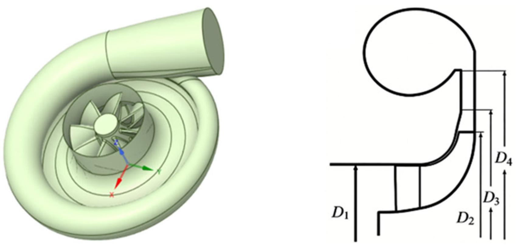
The centrifugal compressor for a turbocharger is selected as the research object in this paper, as shown in Figure 1. The compressor adopts a vaneless diffuser widely used in engineering, with the advantages of simple structure and good adaptability to wide operating conditions.
The geometric parameters of the impeller, inlet and volute are listed in Table 1, which provides an accurate geometric basis for the subsequent numerical simulation and performance analysis. The impeller is designed with 8 main blades and 8 splitter blades, which can effectively balance aerodynamic performance and structural strength. The rated design speed is 65,000 rpm, the design pressure ratio is 3.5, the tip clearance is 0.7 mm, and the tip diameter is 112.2 mm.

2.2. Numerical Method

Ansys CFX 2024R1 was used for numerical simulations, adopting a finite volume method in a finite element framework to discretize and solve the Reynolds Averaged Navier–Stokes (RANS) equations. The Shear-Stress Transport k-ω turbulence model [29] was chosen for its excellent ability to capture flow separation and boundary layer behavior under strong adverse pressure gradients. This is essential for the evaluation of near-stall flow characteristics and off-design performance in centrifugal compressors [30]. For rotor–stator interaction, the Frozen Rotor method was applied at the interfaces between the rotating impeller and stationary domains. This method offers high computational efficiency and good numerical robustness, making it suitable for capturing the main non-axisymmetric flow structures induced by asymmetric stationary components including intake distortion, casing treatments and volutes [31,32]. The governing equations of the SST model, as well as the expressions for pressure ratio and isentropic efficiency, are presented in Equations (1)–(4).
( ρ k ) t + ( ρ u j k ) x j = P ˜ k β * ρ k ω + x j μ + σ k μ t k x j
( ρ ω ) t + ( ρ u j ω ) x j = α ρ S 2 β ρ ω 2 + x j μ + σ ω μ t ω x j + 2 ( 1 F 1 ) ρ σ ω 2 1 ω k x j ω x j
π = P t , o u t / P t , i n
η = [ ( π ) ( γ 1 ) / γ 1 ] / [ T t , o u t / T t , i n 1 ]
where t is the time; xj is the spatial coordinate; ρ is the fluid density; uj is the velocity component; μ and μt are the dynamic viscosity and turbulent eddy viscosity, respectively; k is the turbulent kinetic energy; ω is the specific dissipation rate; P ˜ k is the production term of turbulent kinetic energy; S is the invariant measure of the strain rate; F1 is the blending function; α, β, β*, σk, σω, and σω2 are the closure coefficients for the SST model; Dω is the cross-diffusion term; π is the total pressure ratio of the compressor; Pt,out and Pt,in are the total pressures at the compressor outlet and inlet, respectively; η is the isentropic efficiency of the compressor; Tt,out and Tt,in are the total temperatures at the outlet and inlet, respectively; and γ is the isentropic exponent, taken as 1.4 for air.
To guarantee numerical stability and physical rationality near the stall limit under non-axisymmetric inflow caused by bent-pipe distortion [33], a hybrid outlet boundary strategy was adopted [34,35]. The compressor inlet was set to standard atmospheric conditions, with a total temperature of 298 K and total pressure of 101,325 Pa. Uniform static pressure was applied at the outlet from the choked condition to the peak efficiency point, where the performance curve is steep. From near peak efficiency to the near-stall region, a mass flow rate outlet was instead used to prevent non-physical numerical divergence that commonly occurs as the performance curve gradually flattens [34,35]. For its influence on performance prediction, this hybrid strategy may result in a slightly conservative prediction of the stable flow range, owing to the constraints imposed by mass flow boundaries on local pressure fluctuations [33,34,35].
To determine the stall identification criterion, the stall point in the present numerical simulation is defined as the last stably converged operating point prior to convergence failure [36,37]. Specifically, the residual convergence criterion is set to be 1 × 10⁻⁵. Moreover, the iteration histories of overall mass flow rate and pressure ratio are monitored; one more convergence criterion is set to be that the fluctuation amplitudes of these overall performance indexes are no more than 1% of their average values [38]. Consequently, stall inception is quantitatively identified when the solver fails to meet these criteria, exhibiting continuous fluctuations that strictly exceed the 1% threshold. This definition of numerical stall is widely used as a reliable and conservative indicator of physical stall onset for centrifugal compressors in steady-state calculations [36,37,38,39].
To ensure computational efficiency in the multi-parameter orthogonal optimization process, the steady-state RANS method was employed in this work [14,40]. Although the steady-state assumption cannot capture time-accurate transient flow features and suppresses typical unsteady flow behaviors, such as the local vortex structures induced by the volute tongue or bent-pipe distortion [41], it can greatly reduce computational cost and still yield reliable performance variation laws for geometric optimization [40]. Steady-state RANS still acts as a key approach in the preliminary compressor design phase, for it can reasonably predict the performance characteristics and capture the basic aerodynamic changes in different SRCT schemes at an acceptable computational cost [14,40]. Given that the main purpose of this study is to analyze the relative performance variations including the changes in stable flow range and isentropic efficiency brought by structural adjustments, the steady-state method can guarantee adequate accuracy for comparative studies and thus constitutes a reasonable numerical framework [14,42].

2.3. Domain Division and Grid Independence Verification

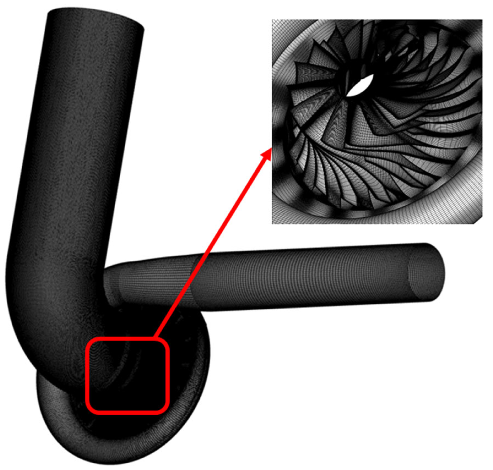
The structure of the computational domain for a centrifugal compressor is jointly determined by the division scheme of the computational domain and the interface connection form. Reasonable domain partitioning directly affects the convergence and accuracy of numerical calculations. For the complex internal geometry of the compressor, a block-based division method is adopted to ensure grid quality, achieve precise control of grid density distribution, and match the corresponding domain connection schemes.
The computational domain is split into 5 parts: inlet section, impeller, diffuser, volute and outlet section, with the impeller using a full-circle grid. As shown in Figure 2, to ensure fully developed inlet/outlet flows, the inlet section is extended by 2.5Din and outlet section by 5.0Dout (Din and Dout are compressor inlet and outlet diameters, respectively). Structured grids are used for the impeller, diffuser and volute to ensure stable flow field parameter transmission; unstructured grids are adopted for extended inlet and outlet sections and self-recirculating casing, with grid refinement on subdomain connecting interfaces. Unstructured grids shorten the grid generation cycle and reduce preprocessing time for orthogonal test multi-parameter schemes.
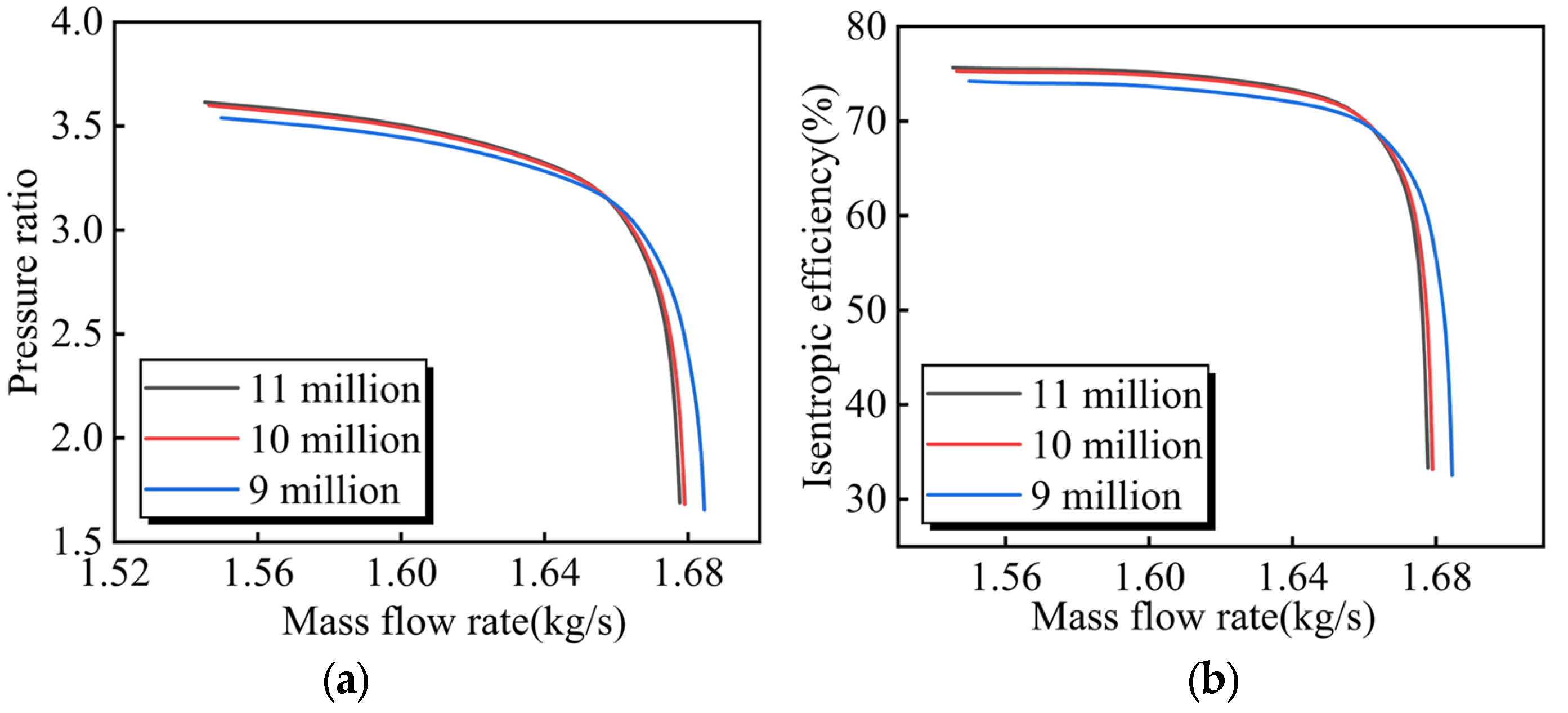
The number of grid cells has a certain influence on the results of numerical simulations. To eliminate errors caused by the number of grid cells, the bent-pipe inlet model without the casing was used to verify grid independence. As shown in Figure 3, three grid densities were evaluated: 9 million, 10 million, and 11 million cells. After balancing computational accuracy and resource efficiency, the configuration of 10 million cells was ultimately selected for subsequent studies. Furthermore, the dimensionless wall distance Y+ was monitored to ensure adequate near-wall grid resolution. Local mesh refinement was applied in regions with steep flow gradients, primarily the impeller blade boundary layers and the volute tongue. The resulting Y+ values remained below 50 across most of the computational domain, successfully satisfying the near-wall treatment requirements of the selected turbulence model.
Numerical discretization uncertainty was quantitatively analyzed using the Grid Convergence Index (GCI) method proposed by Roache [43]. According to the standard GCI calculation procedure, the apparent convergence order p and GCI values for successive grid levels are calculated with Equations (5)–(8).
r 21 = N 1 N 2 1 / 3 , r 32 = N 2 N 3 1 / 3
p = ln | ( ϕ 3 ϕ 2 ) / ( ϕ 2 ϕ 1 ) | ln ( r a v e )
e a 21 = ϕ 1 ϕ 2 ϕ 1 , e a 32 = ϕ 2 ϕ 3 ϕ 2
G C I 21 = F s e a 21 r 21 p 1 , G C I 32 = F s e a 32 r 32 p 1
where N is the total number of grid cells, r is the effective grid refinement ratio, and ϕ denotes key aerodynamic performance parameters such as total pressure ratio π and isentropic efficiency η. Subscripts 1, 2, and 3 refer to fine, medium, and coarse grids, respectively, with N1 > N2 > N3. ea is the approximate relative error between consecutive grid levels, and Fs is the empirical safety factor, recommended as 1.25 for three-grid studies.
Three grid densities, namely N1 = 11 × 106, N2 = 10 × 106, and N3 = 9 × 10⁶ cells, were tested at a constant mass flow rate of 1.587 kg/s. Apparent convergence orders and relative errors were calculated by substituting extracted aerodynamic data into standard GCI formulas. GCI32 values for the medium-coarse grid comparison were 0.68% for total pressure ratio and 0.70% for isentropic efficiency, while GCI21 values for the fine-medium grid comparison were 0.22% and 0.23%, respectively.
Three grid densities with cell counts N1 = 11 × 106, N2 = 10 × 106, and N3 = 9 × 10⁶ were verified at a constant mass flow rate of 1.587 kg/s. Apparent convergence orders and relative errors were calculated by substituting the extracted aerodynamic data into standard GCI formulas. The GCI32 values for the medium-coarse grid comparison were 0.68% for total pressure ratio and 0.70% for isentropic efficiency, while the GCI21 values for the fine-medium grid comparison were 0.22% and 0.23%, respectively.
All GCI32 and GCI21 indices for the medium grid are well below 3%, indicating that the numerical uncertainty is within an acceptable range, consistent with standard CFD verification procedures [44]. Further refinement to 11 million cells yields negligible improvement in prediction accuracy, confirming the medium grid lies well within the asymptotic convergence range. This ensures good grid independence while saving computational resources for subsequent 3D orthogonal simulations.

2.4. Orthogonal Experimental Design for SRCT

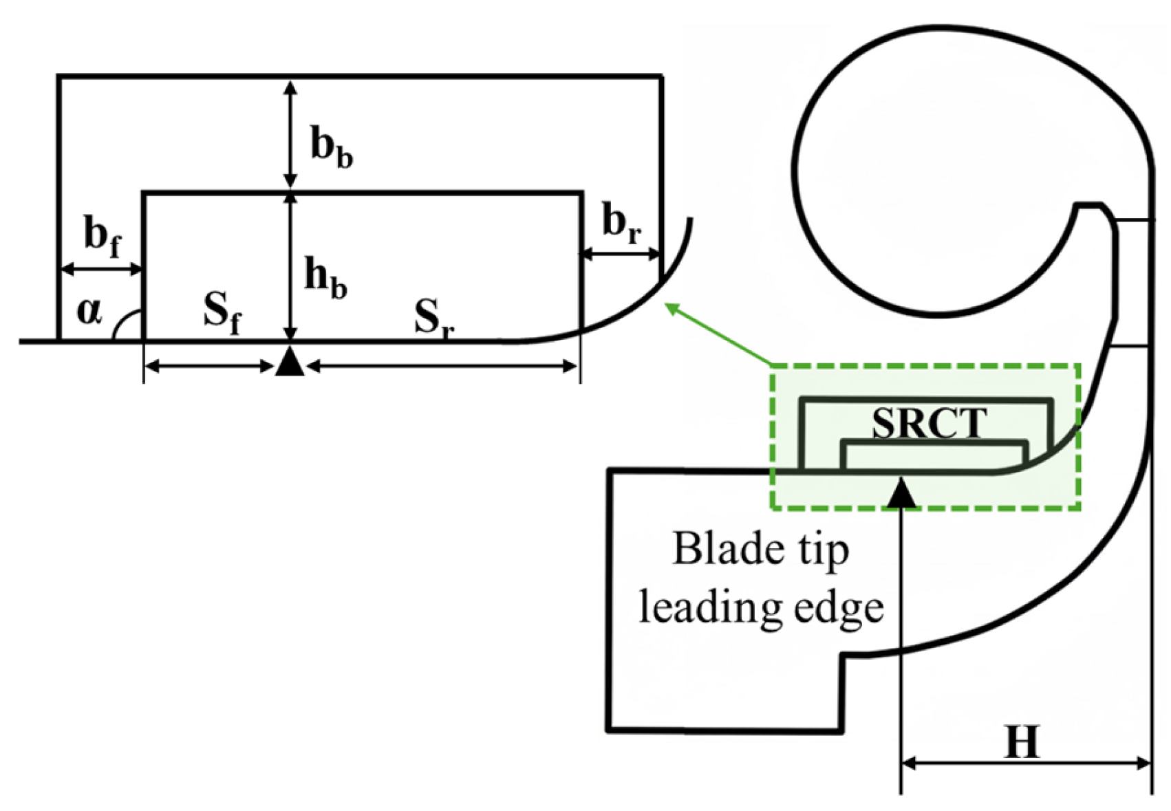
The self-recirculating casing treatment (SRCT) constitutes a meridional bypass channel fundamentally driven by the static pressure gradient across the impeller tip. As illustrated in Figure 4, the SRCT geometry is parameterized by seven independent variables: upstream slot position Sf and width bf, recirculation angle α, axial passage height hb and width bb, and downstream slot position Sr and width br.
The initial SRCT structural parameters were determined using dimensionless parameters, with the impeller axial length H serving as the reference scale [45]. The axial position of the slot was determined based on the compressor’s reference static pressure distribution; the core design criterion ensures that, when the centrifugal compressor operates at the design point, the airflow does not circulate within the casing (ΔP = 0). This initial model is designated as Casing1, with the following specific dimensionless parameters: the upstream slot position Sf/H of 15.92%, the upstream slot width bf/H of 16.12%, downstream slot position Sr/H of 53.40%, downstream slot width br/H of 9.30%, axial passage height hb/H of 11.50%, and axial passage width bb/H of 16.10%.
For self-recirculating casing designs, since they directly alter the low-energy flow structure at the blade tips, compressor performance is highly sensitive to changes in the casing design; consequently, modifications to the self-recirculating casing structure will significantly affect compressor performance. Extensive research indicates that, with regard to compressor performance, four parameters were selected for optimization from seven reference variables: the airflow recirculation angle α, downstream slot width br, axial passage height hb, and axial passage width bb.
To efficiently evaluate parameter sensitivity, the multi-level setting principle involves increasing and decreasing the original value by 25% within the initial structural levels. Each structural factor includes three levels with different values, thereby forming a 4-factor, 3-level orthogonal experiment. This statistical method reduces the number of required numerical evaluations from 81 in a full factorial design to just 9, ensuring full coverage of the parameters while significantly reducing computational costs. Table 2 shows the orthogonal table for the 4-factor, 3-level experiment.
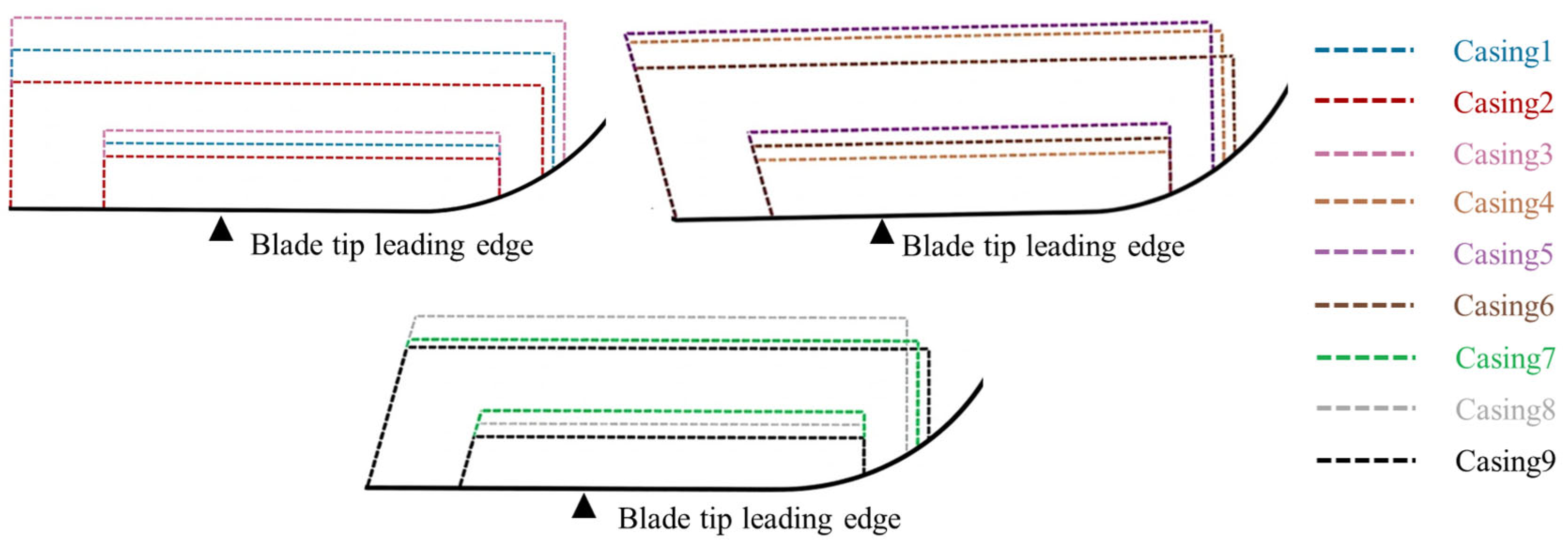
Figure 5 illustrates the meridional configurations of the nine orthogonal schemes, all derived from the original model Casing1. The implementation of the L9(34) orthogonal array inherently guarantees a balanced and uniform dispersion of test points within the design space. This statistical rigorousness mitigates systematic bias and ensures the independent evaluation of each structural parameter, thereby securing the reliability of the optimization results. The three discrete levels prescribed for each optimization variable are concisely defined as follows: α ∈ {75°, 90°, 105°}, br/H ∈ {7.44%, 9.30%, 11.16%}, hb/H ∈ {9.20%, 11.50%, 13.80%}, and bb/H ∈ {12.88%, 16.10%, 19.32%}.

3. Results

3.1. Parametric Optimization via Orthogonal Array

3.1.1. Aerodynamic Performance Evaluation

Through the nine groups of orthogonal test schemes, the balanced combination of the four key structural parameters is realized. On this basis, this study selects the stable flow range (SFR) of the centrifugal compressor and the isentropic efficiency η at the near-stall point as the core evaluation indexes, and takes the dual maximization of SFR and the near-stall point efficiency η as the optimization objective, aiming to screen out the optimal structural configuration of the self-recirculating casing through the test results. SFR is given as shown in Equation (9).
S F R = ( 1 m s t a l l / m c h o k e ) × 100 %
where mchoke is the choked mass flow rate of the compressor; mstall is the near-stall mass flow rate of the compressor.
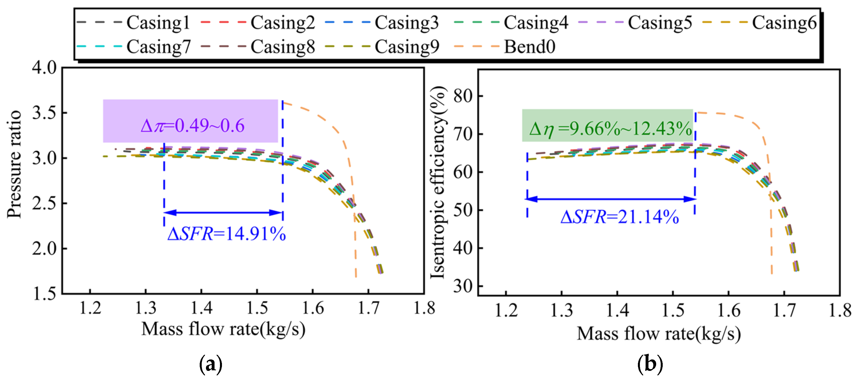
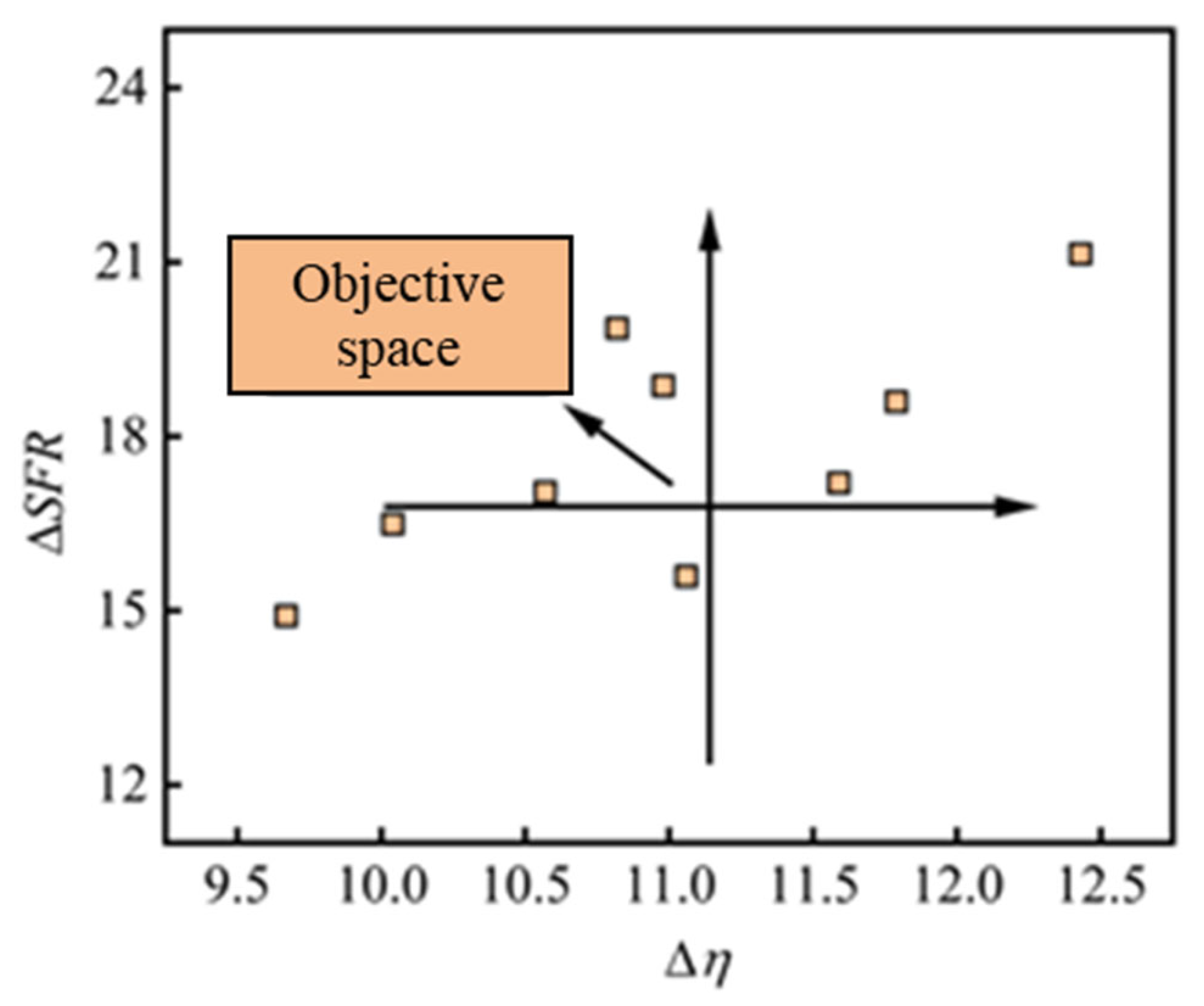
Numerical simulations spanning the entire operating range were conducted for ten configurations: the original bent-pipe model Bend0 and nine orthogonal SRCT schemes, designated Casing1–Casing9. As illustrated by the aerodynamic characteristic curves at 100% design speed in Figure 6, all nine treated configurations significantly broadened the stable operating envelope. The performance curves exhibited a distinct shift toward the lower mass flow region, indicating that the SRCT geometries effectively modulated the tip flow field under distorted inflow and extended the choke limit. Consequently, this resulted in a substantial increase in the SFR, ranging from 14.91% to 21.14%.
While achieving the desired stability enhancement, the self-recirculating casing also incurs a certain loss of aerodynamic performance. Numerical simulation results indicate that the isentropic efficiency of the compressor decreases across the entire flow range after casing installation, with a reduction of 9.66% to 12.43% at the near-stall point, and a total pressure ratio reduction in the range of 0.46 to 0.6. These results fully demonstrate that the self-recirculating casing can effectively expand the stable operating range of the bent-pipe intake centrifugal compressor, while simultaneously causing a certain degree of degradation in the compressor’s pressure rise capacity and aerodynamic efficiency.

3.1.2. Orthogonal Result Analysis

Three optimization models for the self-recirculating casing were established to target the optimal SFR, peak isentropic efficiency, and comprehensive stability enhancement. These models are evaluated based on the stable flow range, the variation in isentropic efficiency η at the near-stall point, and the comprehensive stability enhancement index ∆SFR/∆η, respectively. The calculation of the index ∆SFR/∆η is defined by Equations (10) and (11).
Δ S F R = S F R C a s i n g , i S F R B e n d 0
Δ η = η B e n d 0 η C a s i n g , i
where SFRCasing,i and ηCasing,i are the stable flow range and near-stall isentropic efficiency of the compressor with orthogonal casing treatment, respectively; SFRBend0 and ηBend0 are the stable flow range and near-stall isentropic efficiency of the compressor with the original bent-pipe intake, respectively.
To determine the impact of key structural parameters on each optimization objective, a range analysis—commonly referred to as the R-method—was employed. This approach primarily involves two core stages: calculation and discrimination. As shown in Equations (12) and (13).
K ¯ i j = 1 s m = 1 s y m
R j = max { K ¯ 1 j , , K ¯ r j } min { K ¯ 1 j , , K ¯ r j }
where Krj represents the test result corresponding to the j-th factor at the r-th level; krj represents the average test result of the r-th level for the j-th factor; m is the number of repeated tests performed at each factor level; and Rj is the range of the j-th column, which characterizes the influence degree of the corresponding factor on the test target.
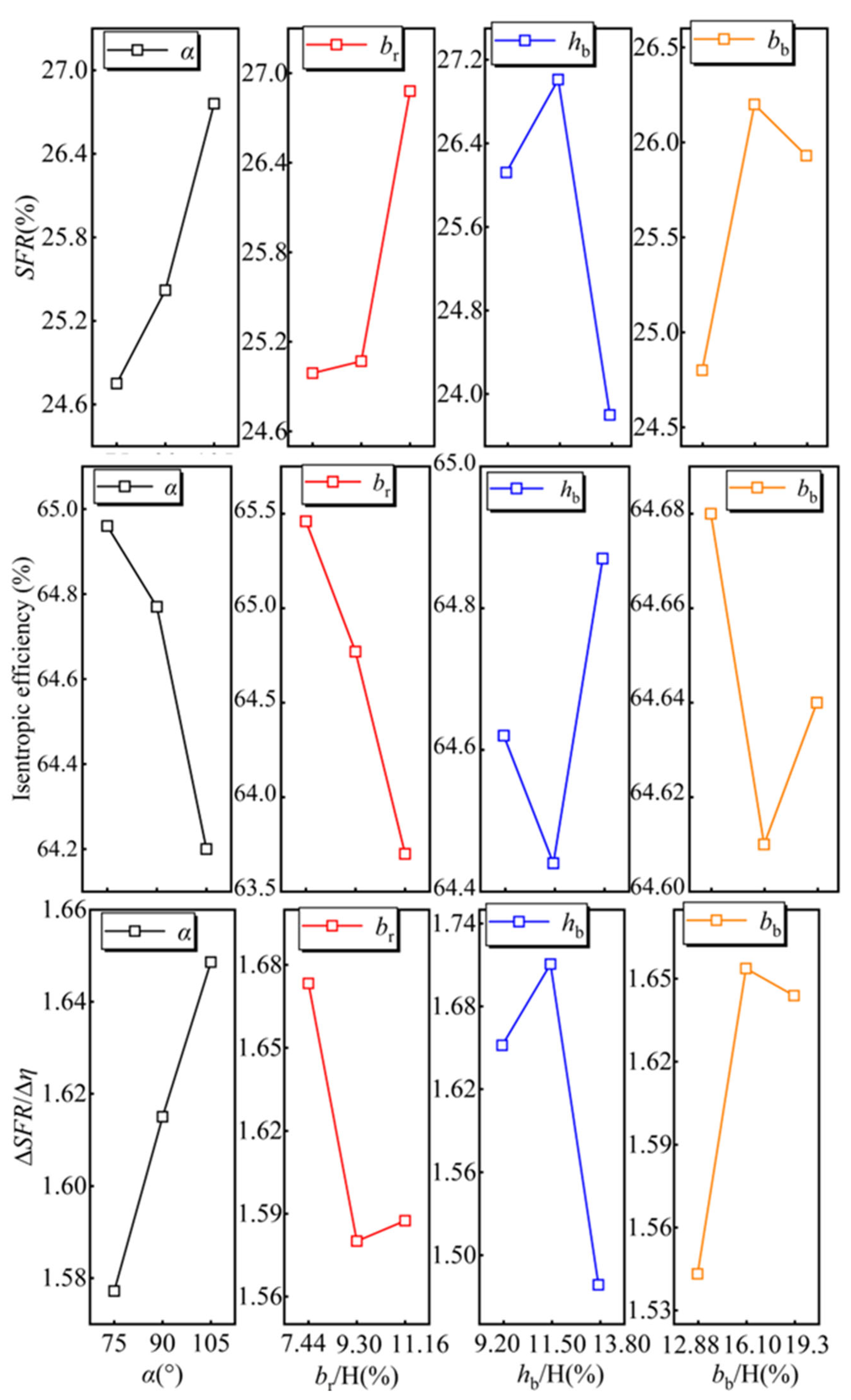
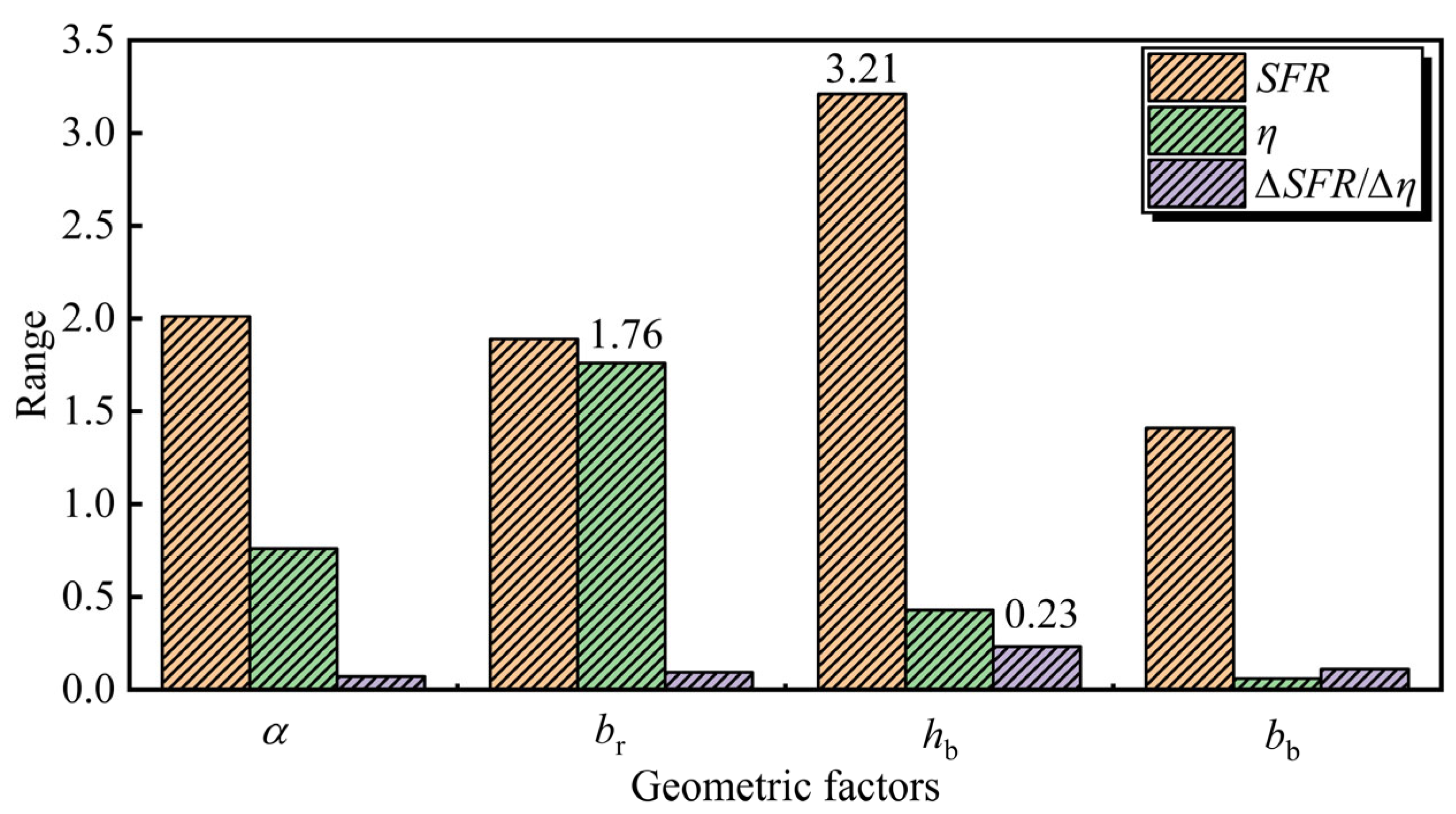
As shown in Figure 7, range analysis shows the significance order of four casing parameters on SFR is hb > α > br > bb, with axial passage height hb and recirculation angle α as core factors. Bent-pipe intake-induced circumferential distortion causes non-uniform tip leakage flow, requiring the casing’s reverse flow passage to adapt to this distortion for efficient recirculation. Larger hb expands the reverse flow passage cross-section, reduces frictional resistance of non-uniform recirculated airflow under this distortion, and improves tip pressure difference-driven recirculation smoothness. Excessively large hb, however, prolongs fluid trajectory, induces flow hysteresis, and forms secondary vortices in the deep cavity, offsetting the stability enhancement effect.
The recirculation angle α directly determines the degree of aerodynamic blockage of the tip leakage flow under pipe-bending distortion conditions. A larger α enhances the reverse momentum of the injected jet, thereby effectively limiting its upstream propagation and expanding the SFR. In contrast, br and bb have a negligible effect on SFR. As shown in the performance curves in Figure 8, SFR increases monotonically with increases in α and br, while hb and bb reach their peaks at moderate levels. Therefore, the optimal configuration for maximizing SFR was determined to be: α = 105°, br/H = 11.16%, hb/H = 11.5%, bb/H = 16.10%.
Regarding the near-stall isentropic efficiency η, the parameter sensitivity ranks strictly as br > α > hb > bb. The inherent intake distortion exacerbates mixing losses between the mainstream and the low-momentum tip fluid. The SRCT introduces additional dissipation through the reinjection process. The downstream slot width br critically controls the recirculated mass flow rate; a reduced br curtails the generation of high-entropy fluid at the source, thereby mitigating shear mixing losses. Furthermore, a larger α amplifies the relative velocity differential between the injected jet and the distorted mainstream, thickening the shear layer and exacerbating aerodynamic penalties. Figure 8 demonstrates that η decreases continuously with increasing α and br. Thus, the optimal efficiency-oriented parameters are identified as α = 75°, br/H = 7.44%, hb/H = 13.8%, bb/H = 12.88%.
For the comprehensive stability enhancement index ∆SFR/∆η, the order of parameter influence significance is hb > bb > br > α, with axial passage height hb and width bb as the dominant factors, which is correlated with the influence law on SFR. The circumferential distortion from bent-pipe intake requires the self-recirculating casing to balance stability enhancement and efficiency preservation. The core role of hb is consistent with that for the SFR optimization objective, and its adaptive regulation achieves efficient stability enhancement under bent-pipe distortion. While bb has a low influence weight on individual SFR or η, it becomes the second critical factor in comprehensive performance evaluation. This is because bb does not directly determine the self-recirculating flow rate, but regulates the axial span of flow control to match the spatial distribution of the tip flow field under bent-pipe distortion. With the optimal axial span, the casing can maximize the improvement of the compressor’s tip flow field at the cost of minimal efficiency loss.
As depicted in Figure 8, the comprehensive stability index ∆SFR/∆η increases monotonically with α, whereas it experiences an initial sharp decline followed by a marginal rebound as br increases. For both hb and bb, the index peaks at intermediate levels. Consequently, the optimal parameter configuration for synergistic stability enhancement is identified as α = 105°, br/H = 7.44%, hb/H = 11.50%, and bb/H = 16.10%.
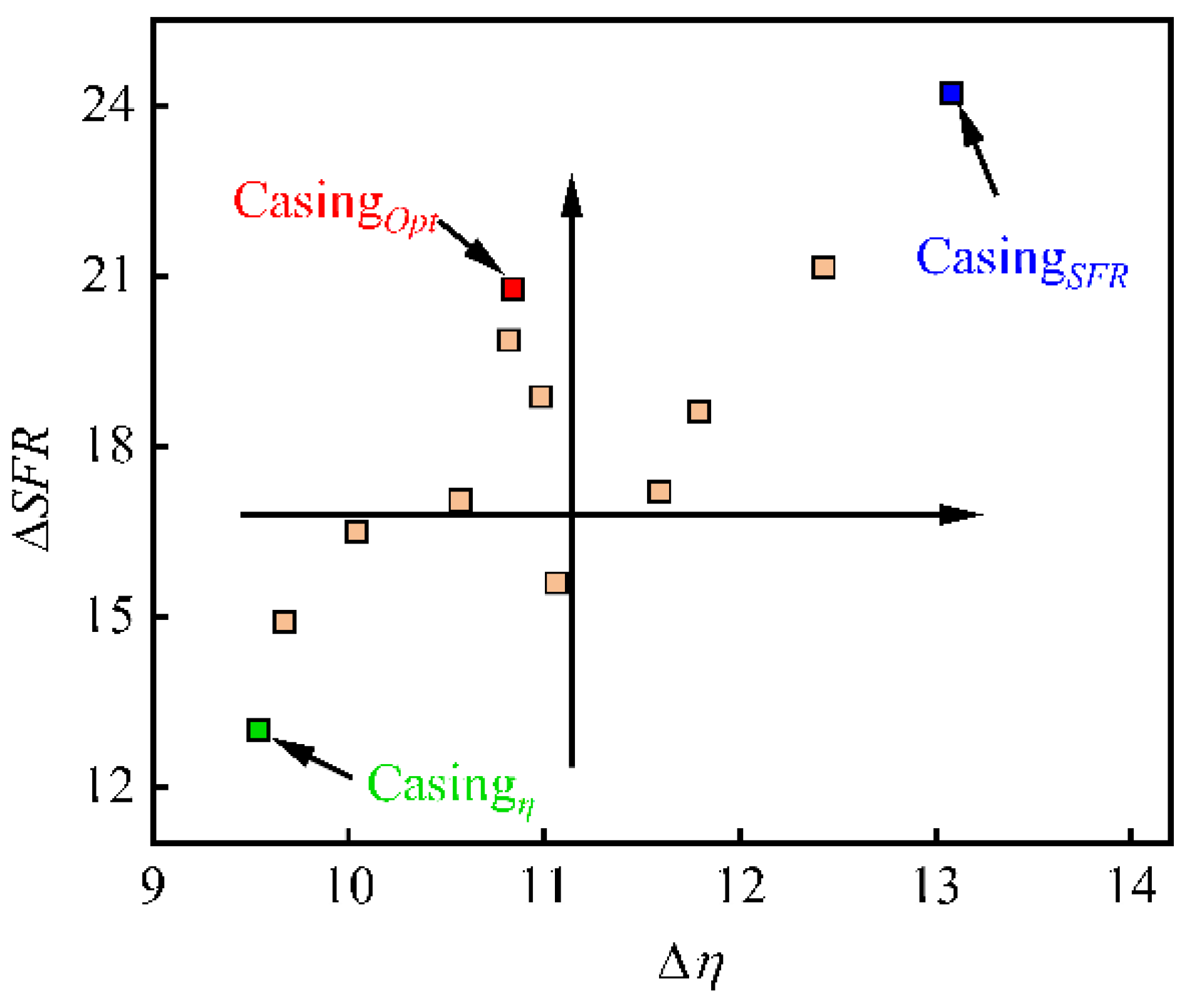
From the perspective of energy transfer, the efficiency losses caused by self-recirculating casings primarily stem from mixing dissipation between the circulating fluid and the distorted inlet flow, friction losses within the passages, and vortex energy dissipation. These inherent losses essentially trade efficiency for a higher stability margin, reflecting the classic trade-off between enhancing stability and maintaining efficiency. As shown in Figure 9, the performance of various casing models exhibits a discrete distribution in the ΔSFRη coordinate system. This spatial distribution directly reflects the differing effects of casing geometry on these two conflicting objectives. The primary optimization objective is to minimize efficiency degradation while maximizing stability, thereby effectively driving the performance point into the upper-left quadrant of the target space—defined by increased ΔSFR and reduced Δη—achieving a synergistic optimization of the centrifugal compressor.

3.1.3. Optimal Configurations

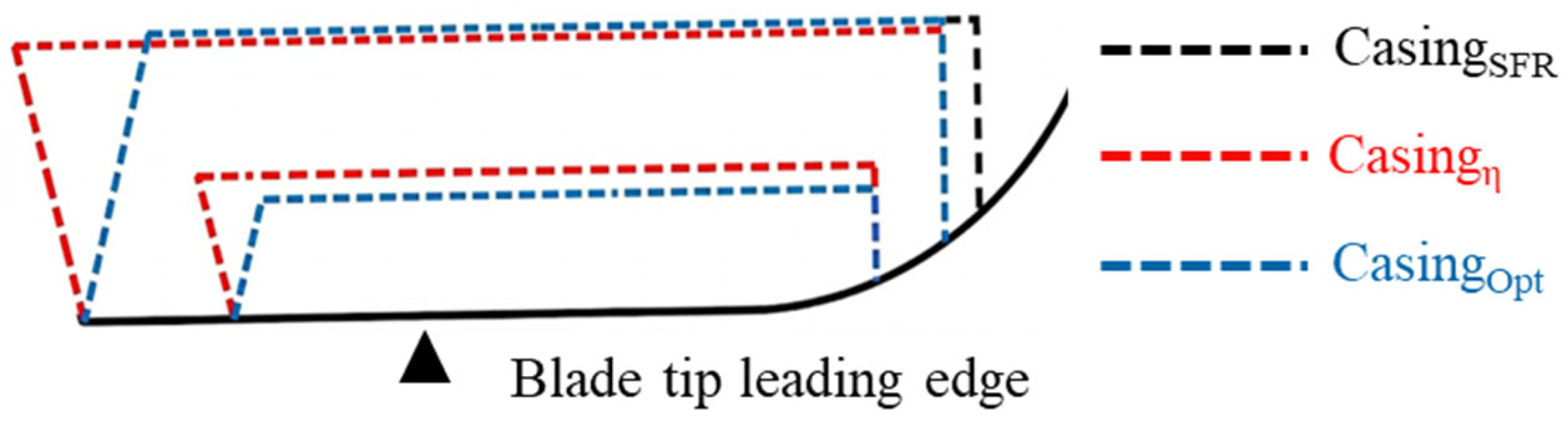
Based on the preceding orthogonal optimization results, the optimal self-recirculating casing configurations for the three distinct optimization objectives are designated as follows: the model targeting the optimal SFR is denoted as CasingSFR, the model prioritizing optimal isentropic efficiency is defined as Casingη, and the model targeting optimal comprehensive stability enhancement is referred to as CasingOpt.
The specific structural parameters of these three optimal models are summarized in Table 3, and their corresponding meridional cross-sectional diagrams are shown in Figure 10. These visualizations clearly illustrate the variations in key geometric parameters across different configurations.

3.2. Analysis of Self-Recirculating Casing Optimization Results

3.2.1. Performance of the Optimized SRCT

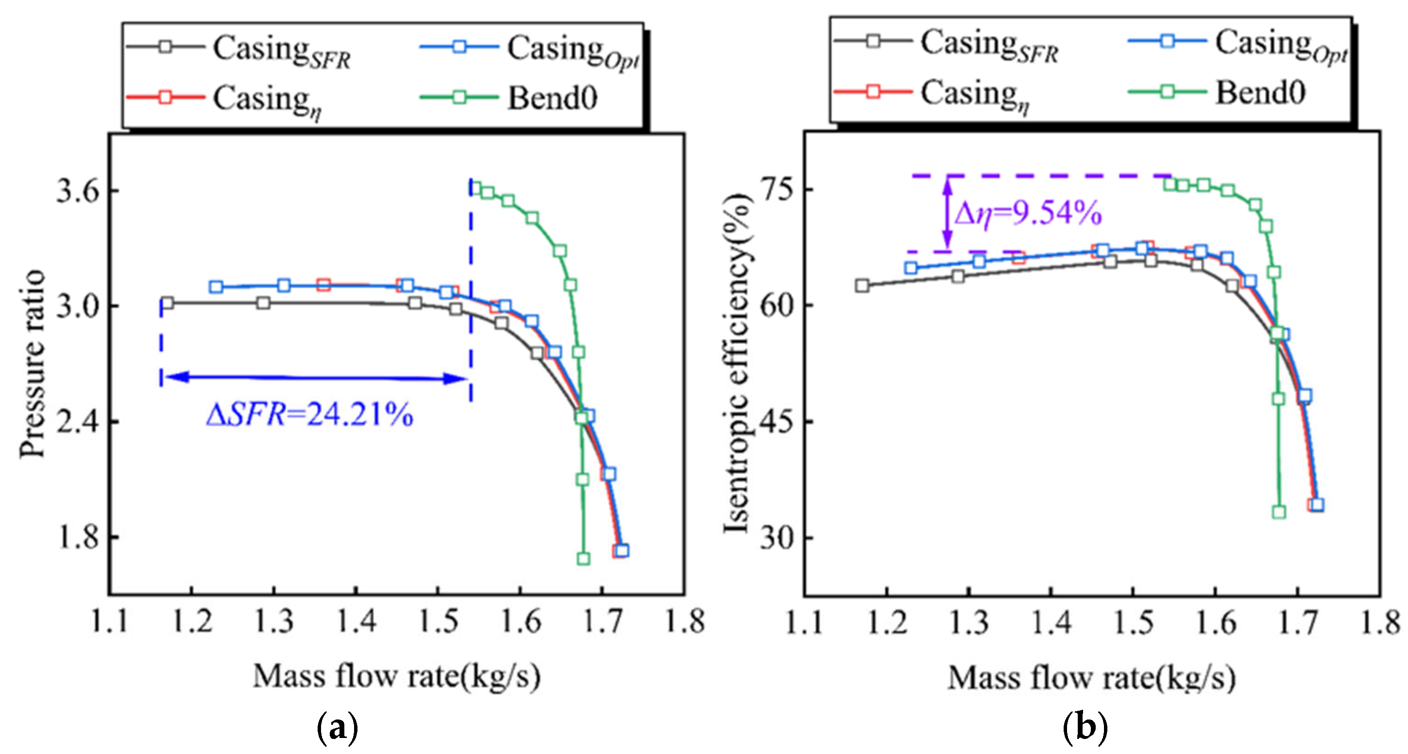
For the three optimized SRCT configurations—named CasingSFR, Casingη, and CasingOpt—a quantitative comparative evaluation of their aerodynamic performance and stability improvements was conducted against the original model Bend0. As shown in the characteristic curves in Figure 11, although all three designs effectively increase the stability margin, they involve significant trade-offs in terms of performance.
Specifically, Casingη maintains the highest pressure ratio and isentropic efficiency across the entire operating range. This model successfully limits the efficiency loss Δη to just 9.54%, but stability is consequently compromised, resulting in the lowest SFR of 20.90% among the optimized variants. In contrast, CasingSFR offers better stability, achieving a peak SFR of 32.11%, which corresponds to a ΔSFR of 24.21%. However, the recirculation configuration significantly reduces the compressor’s aerodynamic performance, resulting in the lowest pressure ratio and isentropic efficiency among the three models.
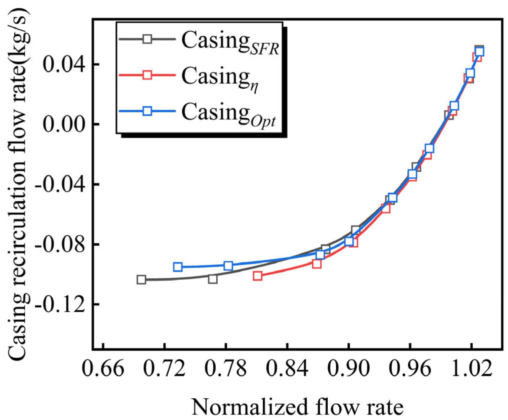
Figure 12 presents the internal circulating flow characteristics of the self-recirculating casing under different operating flow rates, which directly reflect the casing’s regulation intensity on the tip flow field induced by bent-pipe intake. When the circulating flow is positive, the internal flow direction of the casing is consistent with the compressor main flow, with the upstream slot acting as the suction slot and the downstream slot as the injection slot. When the circulating flow is negative, the flow direction is reversed: the downstream slot becomes the suction slot and the upstream slot becomes the injection slot, where low-energy fluid in the impeller tip region is sucked into the casing passage and reinjected into the main flow passage through the upstream slot.
Under high-flow conditions, a positive pressure difference forms between the upstream and downstream slots of the compressor casing, resulting in a positive circulating flow. As the operating flow decreases, the compressor’s pressure boosting capacity increases gradually. The pressure difference between the upstream and downstream slots first reaches equilibrium, followed by the formation of reverse pressure difference, which turns the circulating flow negative. The smaller the operating flow, the larger the reverse pressure difference-driven circulating flow. The circulating flow of the three casings shows an approximately linear distribution with significant inter-model differences in the high flow range, while presenting nonlinear characteristics in the low flow range. As the operating flow rate decreased further, the differences in circulation flow rate among the three models became increasingly pronounced, and the rate of change in flow rate gradually slowed. Among them, the maximum circulating flow of CasingSFR and Casingη is close, while that of CasingOpt is the lowest among the three models.
As shown in Figure 13, a scatter plot compares the operating flow range improvement and near-stall point efficiency loss of the three optimal self-recirculating casings designed in this paper. CasingSFR is located in the first quadrant, with widened SFR but increased efficiency loss. Casingη lies in the third quadrant, with reduced efficiency loss but also decreased SFR. CasingOpt is in the second quadrant: compared with the other models, it achieves increased SFR with reduced efficiency loss, meeting the comprehensive optimization goal of expanding SFR and mitigating efficiency loss.

3.2.2. Flow Field Analysis of Self-Recirculating Casing

To analyze the internal flow characteristics of a compressor and to investigate the effect of a self-recirculating casing on its performance under suction conditions involving bent pipes, this paper examines the internal flow field of the compressor under near-stall conditions based on numerical simulation results.
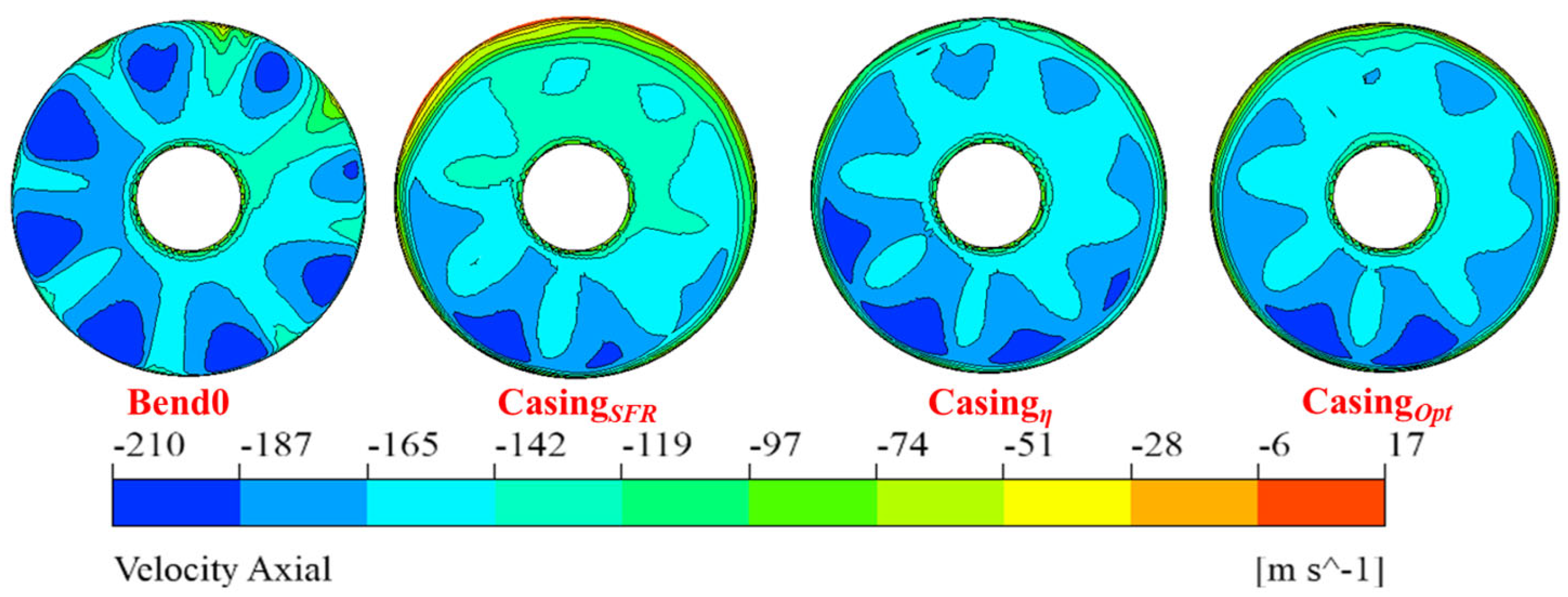
Figure 14 shows the axial velocity contours at the compressor impeller inlet. Negative values denote the primary inflow, whereas positive values signify reverse flow. In the original model Bend0, the synergistic effect of bent-pipe secondary flows and intake distortion generates a highly non-uniform, multi-lobe through-flow distribution. This is accompanied by extensive low-momentum regions and localized reverse flow near the casing, which severely deviate the inlet incidence angle, thereby escalating aerodynamic losses and narrowing the SFR. Although CasingSFR reduces the number of discrete regions and improves the uniformity of the velocity distribution, it still maintains strong local counter-flow. This intense recirculation is consistent with its objective of prioritizing stability. Casingη and CasingOpt exhibit highly similar and regularized flow patterns, with CasingOpt demonstrating better uniformity, reflecting its trade-off between stability and efficiency.
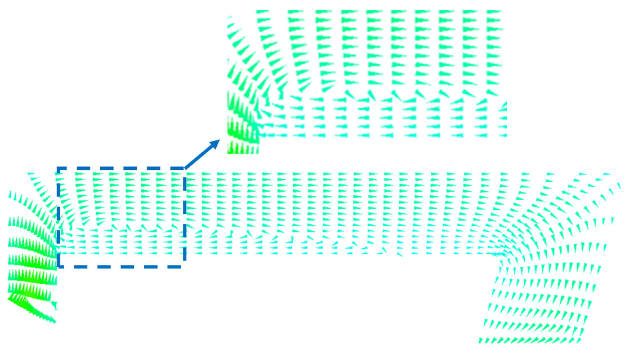
Figure 15 shows the velocity vector distribution on the meridian plane of the casing. The primary flow within the casing moves from the downstream to the upstream side of the compressor; however, secondary flows also develop, resulting in additional flow losses. By further optimizing the casing structure to streamline the internal flow direction and suppress the development of recirculation and secondary flows within the casing, the flow matching between the casing and the compressor can be improved.
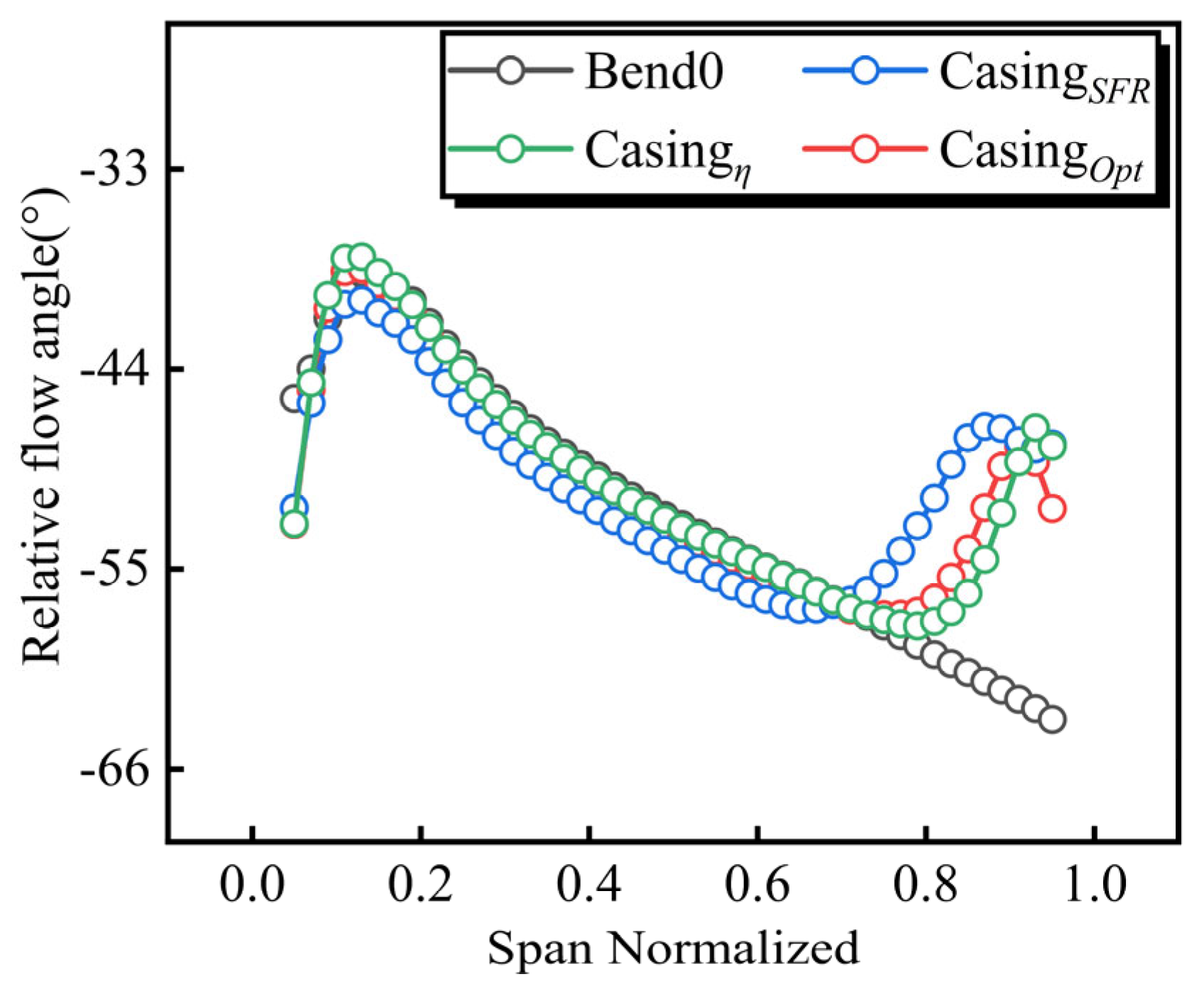
To eliminate the strong viscous shear interference from the boundary layer near the hub and casing, Figure 16 presents the meridional average relative flow angle of the main blades at 5–95% blade height under near-stall conditions to analyze the evolution characteristics of the internal flow. In the original Bend0 model, the flow angle rises sharply to a global peak in the 70–95% tip region, indicating that distorted inflow induces severe tip separation and channel blockage; although the CasingSFR model can reduce the tip flow angle, the flow angle in the 20–70% blade height region is significantly higher than in other models, and the strong jet penetrates excessively, disrupting the main flow structure and resulting in relatively high efficiency losses. The optimal efficiency model Casingη fails to sufficiently alleviate tip separation, making it difficult to broaden the SFR. The comprehensive optimal CasingOpt model achieves precise, targeted control: it not only reduces the peak tip flow angle and broadens the stability margin but also minimizes the disturbance of the jet to the mainstream at medium and low blade heights. Its flow field reconstruction mechanism balances separation modulation with mainstream protection, demonstrating the synergistic advantages of a wide stability margin and high efficiency from an aerothermodynamic perspective.
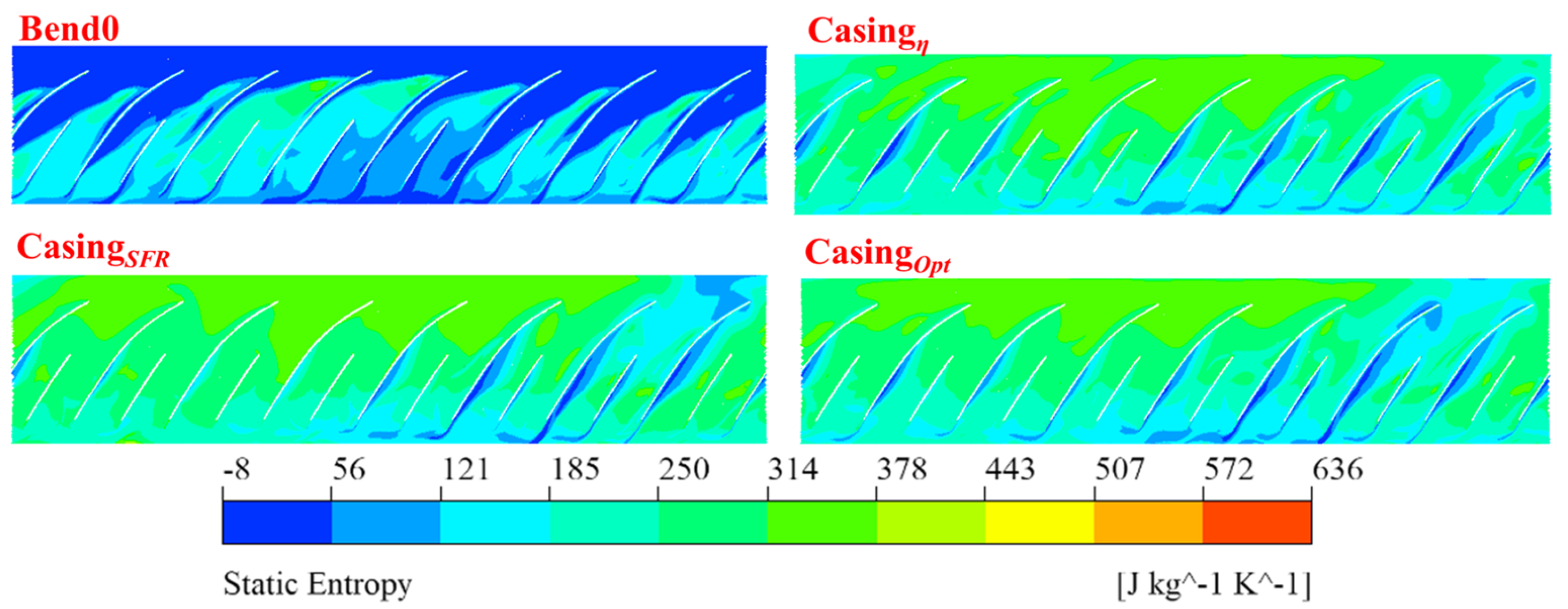
Furthermore, Figure 17 shows the static entropy distribution at 95% of the blade span. The reference design Bend0 maintains a generally low static entropy, but there are strong high-entropy bands extending along the chord within the blade channel. These concentrated loss regions stem from the coupled effects of circumferential inlet distortion and severe angle-of-attack deviation at low mass flow rates, which cause large-scale flow separation at the blade tips and trigger intense shear mixing between the tip leakage flow and the main flow. This local flow separation is the primary cause of stalling. In contrast, although the casing structure causes a slight increase in overall entropy, all three SRCT designs effectively alleviate these large-scale high-entropy bands. By confining local losses primarily to the blade trailing edge, large-scale tip separation is effectively mitigated, thereby broadening the stable flow boundary.
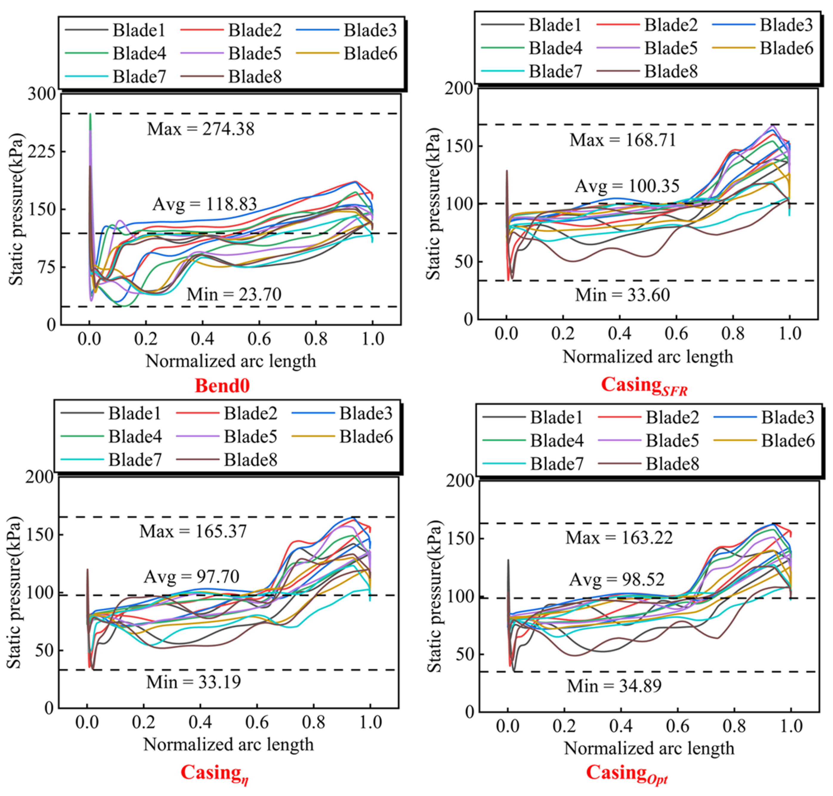
Figure 18 shows the static pressure distribution along the normalized chord length of the eight main blades at 95% of the blade height under near-stall conditions. Consistent with the observed decrease in total pressure ratio, the SRCT geometry exhibits reduced static pressure across the entire chord length compared to the original model Bend0. Specifically, the average static pressure for Bend0 is 118.83 kPa, with a peak of 274.38 kPa. In contrast, the average static pressure for the casing-optimized configurations CasingSFR, Casingη, and CasingOpt decreased to 100.35 kPa, 97.70 kPa, and 98.52 kPa, respectively. Furthermore, the peak pressure values for these models also decreased significantly, to 168.71 kPa, 165.37 kPa, and 163.22 kPa, respectively.
The original model Bend0 exhibits a pressure deviation at the leading edge, but maintains a relatively uniform and consistent static pressure distribution in the mid-to-rear sections. The casing treatment successfully alleviated local low-pressure extremes at the leading edge, thereby modulating separation and expanding the stable flow range; however, it also compromised overall uniformity. Specifically, it introduced a significant static pressure drop near the mid-chord region, leading to pronounced inter-blade pressure differentials that severely exacerbated load distribution non-uniformity along the entire blade length. SRCT expands the stability margin by asymmetrically modulating the leading-edge flow field, rather than homogenizing the circumferential pressure field. When interacting with inherent bends in the duct, this localized control effectively broadens the stable flow range but inevitably generates secondary flow field inhomogeneities, thereby amplifying the full-span pressure distribution between blades.
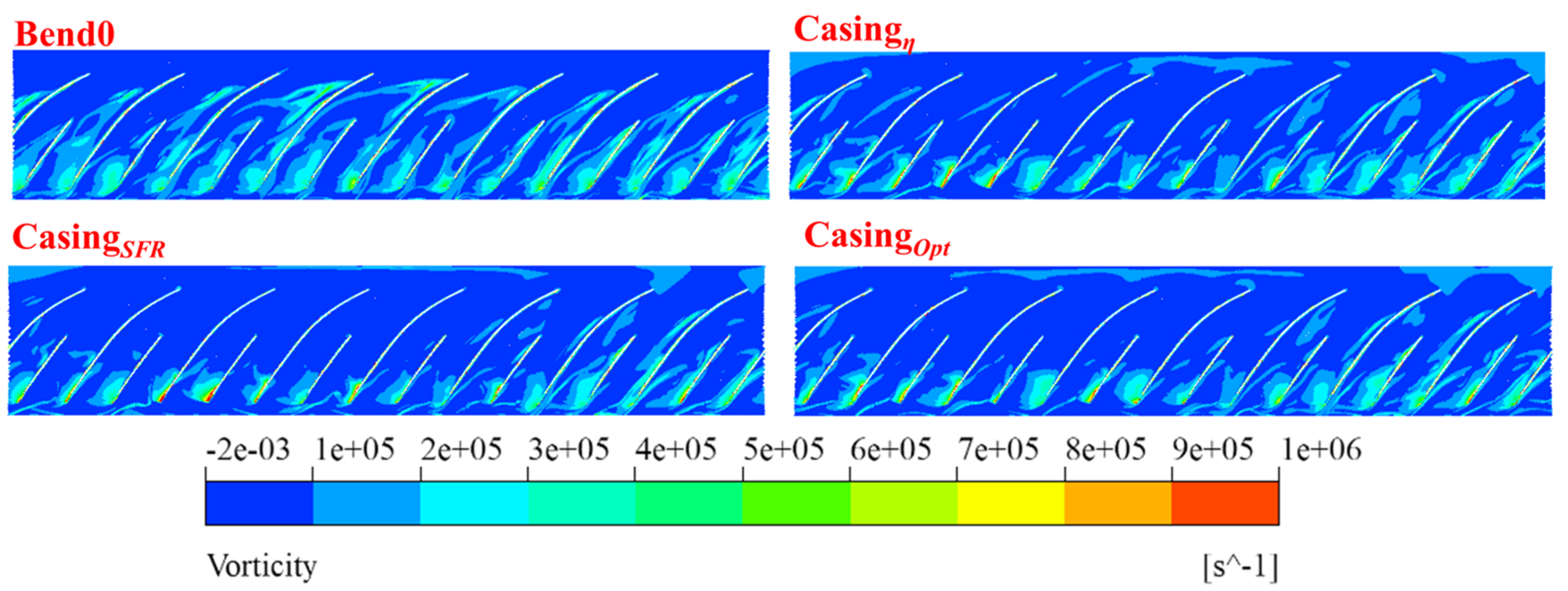
Figure 19 presents the vorticity contours at 95% span of the compressor. For the baseline model Bend0 with a bent-pipe intake, the inlet distortion gives rise to strong shear layers near the blade leading edge, accompanied by large-scale high-vorticity regions. Meanwhile, the vorticity distribution among different blade passages shows distinct circumferential asymmetry, which indicates the occurrence of severe local flow separation in the tip region under distorted inflow. By contrast, the application of casing treatment significantly mitigates both the range and peak strength of the high-vorticity zone near the leading edge. The asymmetric suction effect of the casing treatment alleviates shear layer intensity in the tip region and weakens the high-vorticity separation structures at the leading edge, resulting in more uniform flow distribution between blade passages and therefore enhanced flow field stability.
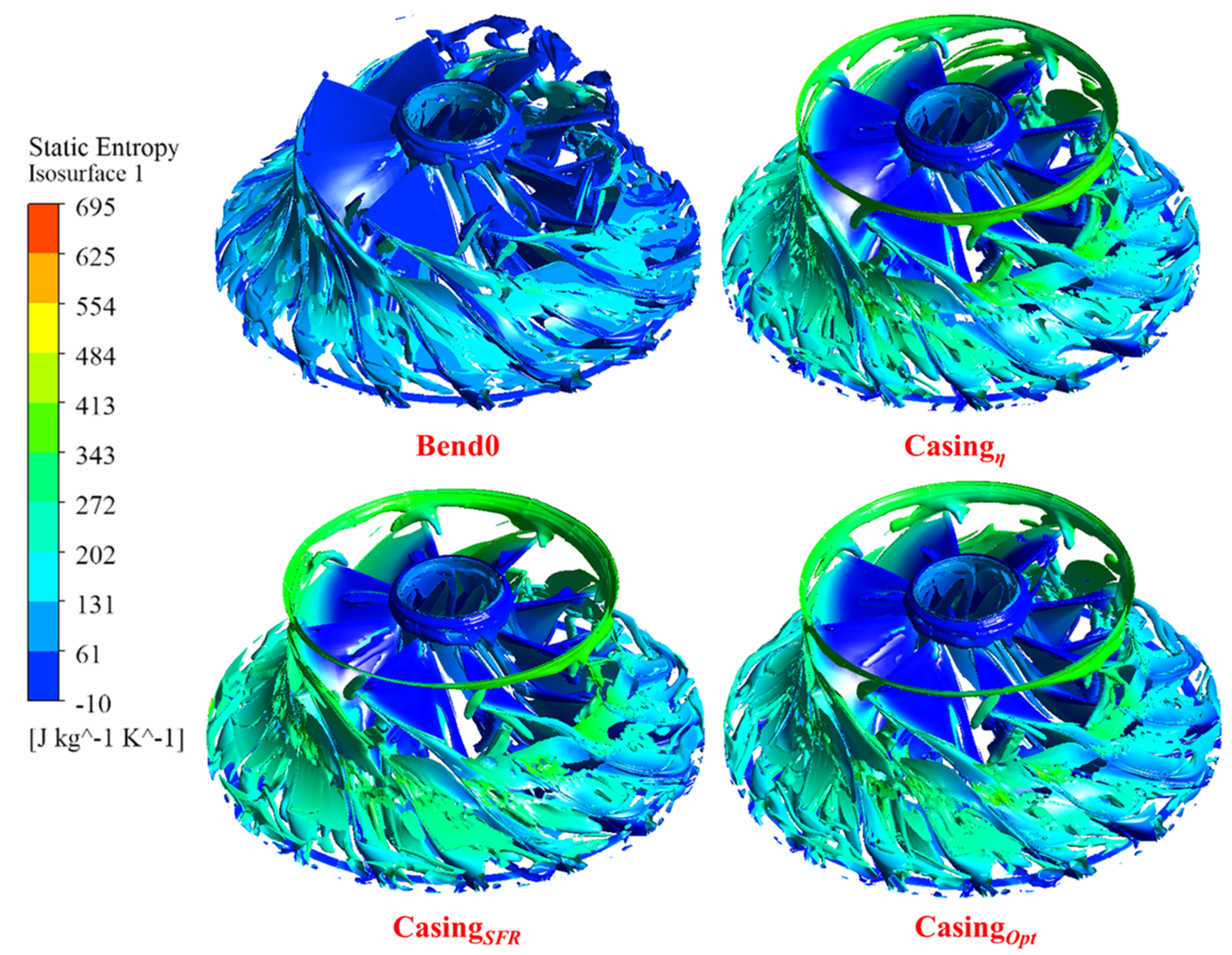
Figure 20 shows the vortex structure distribution within the impeller based on the Q-criterion, colored by static entropy to quantitatively characterize the aerodynamic losses associated with different vortex contour profiles. A uniform threshold of Q = 2 × 10⁸ s−2 is adopted to identify the vortex structures in the impeller passages. In these contour profiles, regions exhibiting elevated static entropy levels represent the physical signature of severe vortex breakdown and intense turbulent mixing dissipation, whereas lower entropy contours correspond to relatively coherent and stable vortex structures. For the baseline Bend0 model under non-uniform distorted inflow, the tip leakage vortex breaks down into fragmented vortex clusters featured by high static entropy, which further causes passage blockage and aerodynamic dissipation. In comparison, the application of casing treatment brings a local entropy rise near the inlet wall due to reinjection flow mixing. Notably, the suction mechanism of the self-recirculating casing induces new localized vortex structures at the impeller inlet, representing a specific flow response to the casing treatment’s modulation. However, the highly fragmented vortex structures in the main flow passages are greatly alleviated. The tip leakage vortex recovers its spatial coherence and migrates toward the low static entropy region as a whole. This phenomenon is consistent with the two-dimensional static entropy distribution at 95% span presented in Figure 17. The high-entropy fluid in the blade passages shown in Figure 17 corresponds to the sectional projection of the severe three-dimensional tip leakage vortex breakdown. Through the asymmetric suction effect, the optimized self-recirculating casing treatment maintains the structural integrity of the three-dimensional tip leakage vortex and effectively weakens vortex breakdown, so as to reduce the overall aerodynamic losses in the main flow passages.

4. Conclusions

This study investigates centrifugal compressors equipped with bent-pipe intakes, and carries out a preliminary numerical screening of self-recirculating casing treatment through multi-objective orthogonal optimization, with the objective of expanding the stable operating range while reducing accompanying aerodynamic performance losses. Numerical simulations are performed at 65,000 rpm using the SST k-ω turbulence model and Frozen Rotor mixing planes. Different from conventional single-variable studies, the present work focuses on the nonlinear coupling effects of key geometric parameters under distorted inflow conditions. The main conclusions can be summarized as follows:
(1)
Range analysis reveals the order of importance of the four key SRCT geometric parameters: For SFR, the order is hb > α > br > bb; for near-stall isentropic efficiency η, the order is br > α > hb > bb; for the comprehensive stability index ΔSFRη, the order is hb > bb > br > α. The axial channel height hb is the dominant factor in improving stability, while the downstream slot width br is the core control parameter leading to efficiency losses.
(2)
Based on the experimental outcomes, three optimized casing configurations were established, specifically CasingSFR, Casingη, and CasingOpt. Numerical verification demonstrates that CasingSFR maximizes the SFR to 32.11%, while Casingη minimizes the efficiency penalty to 9.54%. Notably, CasingOpt achieves a synergistic balance, yielding a 28.67% SFR with a moderate efficiency loss of 10.84%, successfully realizing collaborative optimization.
(3)
Flow field analysis reveals that the inherent distortion of the bent-pipe intake is the core cause of non-uniform impeller inlet flow, concentrated tip losses, and limited stability margin of the original compressor. The optimized SRCT effectively sucks low-energy tip leakage flow, regularizes the inlet incidence, and modulates flow separation and high-entropy loss at the blade tip leading edge to expand the stable flow range. In addition, the asymmetric suction introduced by SRCT reduces the shear layer intensity in the tip region and significantly mitigates the high-vorticity separation structures. It inhibits the breakdown of the three-dimensional tip leakage vortex into fragmented high-entropy vortex clusters, allowing the vortex to regain spatial coherence and thus lowering the overall aerodynamic losses within the main flow passages. It expands the stability margin via asymmetric modulation of the leading-edge flow field rather than homogenizing the circumferential pressure field, which inevitably introduces additional flow loss and circumferential non-uniformity of blade load.
It is explicitly acknowledged that this work serves as a preliminary numerical screening study relying on steady-state simulations. Future work will involve high-fidelity transient simulations and experimental benchmark validation to further verify these numerical predictions.

Author Contributions

Conceptualization, X.L. and J.S.; methodology, X.L., J.S. and L.L.; software, J.S. and Y.T.; validation, J.S., Y.H., Y.T. and L.L.; formal analysis, J.S., Y.H. and L.L.; investigation, J.S. and Y.H.; resources, X.L.; data curation, J.S. and Y.H.; writing—original draft preparation, J.S.; writing—review and editing, X.L. and L.L.; visualization, J.S. and Y.T.; supervision, X.L.; project administration, X.L.; funding acquisition, X.L. All authors have read and agreed to the published version of the manuscript.

Funding

This work was funded by basic product innovation program vehicle power research project (DEDP2023001).

Data Availability Statement

The original contributions presented in the study are included in the article, further inquiries can be directed to the corresponding author.

Conflicts of Interest

The authors declare no conflicts of interest.

References

  1. Zhang, L.; Jia, W.; An, G.; Lang, J.; Yuan, W.; Li, H. Centrifugal compressors in compressed supercritical carbon dioxide energy storage systems: Critical review of design methodologies and industrial applications. J. Energy Storage 2025, 131, 117278. [Google Scholar] [CrossRef] [Scilit]
  2. Zhou, Y.; Li, X.; Geng, T.; Shao, L.; Xu, Z.; Zhong, Z.; Zhu, K.; Song, Y.; Ding, S. Piston engine energy utilization for variable-altitude applications: A review of two-stage turbocharging technologies. Renew. Sustain. Energy Rev. 2025, 223, 116036. [Google Scholar] [CrossRef] [Scilit]
  3. Li, X.; Huang, N.; Chen, G.; Zhang, Y.; Zhao, Y.; Zhang, J.; Tong, D. Numerical Simulation on the Influence of Inlet Flow Characteristics on the Performance of a Centrifugal Compressor. Energies 2023, 16, 3869. [Google Scholar] [CrossRef] [Scilit]
  4. Zhao, B.; Sun, H.; Wang, L.; Song, M. Impact of inlet distortion on turbocharger compressor stage performance. Appl. Therm. Eng. 2017, 124, 393–402. [Google Scholar] [CrossRef] [Scilit]
  5. Dong, X.; Wang, Y.; Li, J.; Geng, C.; Sun, D.; Sun, X. Effects of impedance-boundary-controlled casing treatment on the fan performance with eccentric inlet swirl. Exp. Therm. Fluid. Sci. 2025, 161, 111339. [Google Scholar] [CrossRef] [Scilit]
  6. Wang, H.; Mao, X.; Liu, B.; Qing, Y. Combined flow control with full-span slot and end-wall boundary layer suction in a large-camber compressor cascade. Aerosp. Sci. Technol. 2021, 119, 107121. [Google Scholar] [CrossRef] [Scilit]
  7. Day, I.J. Stall, surge, and 75 years of research. J. Turbomach. 2016, 138, 011001. [Google Scholar] [CrossRef] [Scilit]
  8. Zheng, X.; Sun, Z.; Kawakubo, T.; Tamaki, H. Stability improvement of a turbocharger centrifugal compressor by a nonaxisymmetric vaned diffuser. J. Turbomach. 2018, 140, 041007. [Google Scholar] [CrossRef] [Scilit]
  9. Semlitsch, B.; Mihaescu, M. Flow phenomena leading to surge in a centrifugal compressor. Energy 2016, 103, 572–587. [Google Scholar] [CrossRef] [Scilit]
  10. Yang, Q.; Li, L.; Zhao, Y.; Xiao, J.; Shu, Y.; Zhang, Q. Experimental investigation of an active control casing treatment of centrifugal compressors. Exp. Therm. Fluid. Sci. 2017, 83, 107–117. [Google Scholar] [CrossRef] [Scilit]
  11. Wu, W.; Zhao, J.; Zhong, J. Influence of the rotating direction and speed of controllable speed casing on the flow stability of a transonic compressor rotor under design condition. Aerosp. Sci. Technol. 2022, 126, 107630. [Google Scholar] [CrossRef] [Scilit]
  12. Chen, H.; Lei, V.-M. Casing Treatment and Inlet Swirl of Centrifugal Compressors. J. Turbomach. 2013, 135, 041010. [Google Scholar] [CrossRef] [Scilit]
  13. Ullah, T.; Sobczak, K.; Liskiewicz, G.; Mucha, M. Numerical Investigations of Inlet Recirculation in a Turbocharger Centrifugal Compressor. Energies 2025, 18, 903. [Google Scholar] [CrossRef] [Scilit]
  14. Yang, M.; Martinez-Botas, R.; Zhang, Y.; Zheng, X. Effect of Self-Recirculation-Casing Treatment on High Pressure Ratio Centrifugal Compressor. J. Propuls. Power 2016, 32, 602–610. [Google Scholar] [CrossRef] [Scilit]
  15. Wang, H.; Zhang, H.G.; Chu, W.L.; Jing, F. Experimental and numerical investigation on stability enhancement mechanisms of self-recirculating casing treatment. Aerosp. Sci. Technol. 2026, 168, 110951. [Google Scholar] [CrossRef] [Scilit]
  16. Ding, S.; Chen, S.; Li, Z. Stability enhancement using a new combined casing treatment strategy in an ultra-highly loaded transonic compressor rotor. Aerosp. Sci. Technol. 2024, 154, 109505. [Google Scholar] [CrossRef] [Scilit]
  17. Ding, S.; Chen, S.; Wang, S.; Wang, Z. Flow mechanism of self-recirculating casing treatment in a low-reaction transonic compressor rotor. Aerosp. Sci. Technol. 2022, 130, 107925. [Google Scholar] [CrossRef] [Scilit]
  18. Guo, Y.; Mao, X.; Gao, L. Numerical investigation on the cross-stage self-recirculating casing treatment for a counter-rotating axial compressor. Aerosp. Sci. Technol. 2023, 135, 108161. [Google Scholar] [CrossRef] [Scilit]
  19. Liu, W.; Chu, W.; Zhang, H.; Dong, J. Experimental and Numerical Study of Recirculation Hybrid Casing Treatments in a High-Speed Axial Flow Compressor. Aerosp. Sci. Technol. 2026, 171, 111617. [Google Scholar] [CrossRef] [Scilit]
  20. Ma, S.-B.; Kim, K.-Y. Optimization of discrete cavities in a centrifugal compressor to enhance operating stability. Aerosp. Sci. Technol. 2017, 68, 308–319. [Google Scholar] [CrossRef] [Scilit]
  21. Vuong, T.D.; Kim, K.Y.; Dinh, C.T. Recirculation-groove coupled casing treatment for a transonic axial compressor. Aerosp. Sci. Technol. 2021, 111, 106556. [Google Scholar] [CrossRef] [Scilit]
  22. Fan, Z.; Wu, Y.; Ba, D.; Zhang, M.; Liu, Y.; Du, J. Design optimization of axial slot casing treatment and blade in an axial compressor based on deep learning and reinforcement learning. Aerosp. Sci. Technol. 2025, 162, 110209. [Google Scholar] [CrossRef] [Scilit]
  23. Li, X.; Liu, Z.; Zhao, M.; Zhao, Y.; He, Y. Stability improvement without efficiency penalty of a transonic centrifugal compressor by casing treatment and impeller/diffuser coupling optimization. Aerosp. Sci. Technol. 2022, 127, 107685. [Google Scholar] [CrossRef] [Scilit]
  24. Zhao, Y.; Liu, Z.; Fu, L.; Zhao, M.; Li, X. Redesign of a turbocharger compressor based on multi-component full-passage optimization. Aerosp. Sci. Technol. 2023, 142, 108644. [Google Scholar] [CrossRef] [Scilit]
  25. Yang, M.Y.; Ricardo, M.-B.; Deng, K.; Zhang, W.; Zheng, X. Unsteady influence of Self Recirculation Casing Treatment (SRCT) on high pressure ratio centrifugal compressor. Int. J. Heat. Fluid. Flow. 2016, 58, 19–29. [Google Scholar] [CrossRef] [Scilit]
  26. Pan, T.; Wu, W.; Li, Q. Effect of casing treatment to switch the type of instability inception in a high-speed axial compressor. Aerosp. Sci. Technol. 2021, 115, 106801. [Google Scholar] [CrossRef] [Scilit]
  27. Wang, L.; Mao, X.; Gao, L.; Guo, Y.; Yu, Y. Effect of axial slot casing treatment on the flow instability for different speed ratios in a counter-rotating axial flow compressor. Aerosp. Sci. Technol. 2023, 139, 108374. [Google Scholar] [CrossRef] [Scilit]
  28. Zhao, B.; Zhou, T.; Yang, C. Experimental investigations on effects of the self-circulation casing treatment on acoustic and surge characteristics in a centrifugal compressor. Aerosp. Sci. Technol. 2022, 131, 108002. [Google Scholar] [CrossRef] [Scilit]
  29. Menter, F.R. Two-equation eddy-viscosity turbulence models for engineering applications. AIAA J. 1994, 32, 1598–1605. [Google Scholar] [CrossRef] [Scilit]
  30. Gibson, L.; Galloway, L.; Kim, S.I.; Spence, S. Assessment of turbulence model predictions for a centrifugal compressor simulation. J. Glob. Power Propuls. Soc. 2017, 1, 142–156. [Google Scholar] [CrossRef] [Scilit]
  31. Hillewaert, K.; Van den Braembussche, R.A. Numerical Simulation of Impeller-Volute Interaction in Centrifugal Compressors. J. Turbomach. 1999, 121, 603–608. [Google Scholar] [CrossRef] [Scilit]
  32. Ceyrowsky, T.; Hildebrandt, A.; Schwarze, R. Numerical Investigation of the Circumferential Pressure Distortion Induced by a Centrifugal Compressor’s External Volute. In Proceedings of the ASME Turbo Expo 2018, Oslo, Norway, 11–15 June 2018; p. V02BT44A015. [Google Scholar] [CrossRef] [Scilit]
  33. Wang, L.; Lao, D.; Liu, Y.; Yang, C. Non-axisymmetric flow characteristics in centrifugal compressor. J. Therm. Sci. 2015, 24, 313–322. [Google Scholar] [CrossRef] [Scilit]
  34. Galindo, J.; Tiseira, A.; Navarro, R.; Tarí, D.; Meano, C.M. Effect of the inlet geometry on performance, surge margin and noise emission of an automotive turbocharger compressor. Appl. Therm. Eng. 2017, 110, 875–882. [Google Scholar] [CrossRef] [Scilit]
  35. Wei, K.; Zuo, S.; He, H.; Wang, Z. Numerical study on the unsteady behavior of a centrifugal compressor for the fuel-cell vehicle. Proc. Mtgs. Acoust. 2014, 21, 040008. [Google Scholar] [CrossRef] [Scilit]
  36. Zamiri, A.; Choi, M.; Chung, J.T. Numerical investigation of rotating stall characteristics in a full-annulus transonic centrifugal compressor. J. Propuls. Power 2021, 37, 369–380. [Google Scholar] [CrossRef] [Scilit]
  37. Oh, M.H.; Ko, J.; Park, J.Y.; Choi, M. Optimization of a circumferential groove in a centrifugal compressor. Int. J. Turbo Jet.-Engines 2023, 40, 411–424. [Google Scholar] [CrossRef] [Scilit]
  38. Fan, T.; Wang, B.; Yan, C.; Zhang, W.; Song, Z.; Zheng, X. Effect of Self-Recirculating Casing Treatment on the Aerodynamic Performance of Ultra-High-Pressure-Ratio Centrifugal Compressors. Processes 2023, 11, 2439. [Google Scholar] [CrossRef] [Scilit]
  39. Zhang, H.; Jing, F.; Li, Q.; Wang, H.; Chu, W. Mechanism Affecting the Performance and Stability of a Centrifugal Impeller by Changing Bleeding Positions of Self-Recirculating Casing Treatment. Aerospace 2023, 10, 104. [Google Scholar] [CrossRef] [Scilit]
  40. Casey, M.; Robinson, C. A Method to Estimate the Performance Map of a Centrifugal Compressor Stage. J. Turbomach. 2013, 135, 021034. [Google Scholar] [CrossRef] [Scilit]
  41. Yang, C.; Wang, Y.; Tong, D.; Yang, C.; Li, Y. Stall inception induced by the volute tongue at centrifugal compressor inlet. Proc. IMechE Part G J. Aerosp. Eng. 2017, 231, 931–940. [Google Scholar] [CrossRef] [Scilit]
  42. Zhang, H.; Wang, H.; Li, Q.; Jing, F.; Chu, W. Mechanism Underlying the Effect of Self-Circulating Casings with Different Circumferential Coverage Ratios on the Aerodynamic Performance of a Transonic Centrifugal Compressor. Aerospace 2023, 10, 312. [Google Scholar] [CrossRef] [Scilit]
  43. Roache, P.J. Quantification of uncertainty in computational fluid dynamics. Annu. Rev. Fluid. Mech. 1997, 29, 123–160. [Google Scholar] [CrossRef] [Scilit]
  44. Celik, I.B.; Ghia, U.; Roache, P.J.; Freitas, C.J.; Coleman, H.; Raad, P.E. Procedure for estimation and reporting of uncertainty due to discretization in CFD applications. J. Fluids Eng. 2008, 130, 078101. [Google Scholar] [CrossRef] [Scilit]
  45. Wang, Z.; Zheng, L.; Meng, W.; Yanhua, W.; Feng, Q. Investigation of methods to enhance the stable operating range of high-pressure ratio centrifugal compressors adopted in the compressed air energy storage system. J. Energy Storage 2025, 121, 116539. [Google Scholar] [CrossRef] [Scilit]
Figure 1. The geometric structure of a centrifugal compressor.
Processes 14 01499 g001
Figure 2. Grid generation of centrifugal compressor.
Processes 14 01499 g002
Figure 3. Grid independence verification. (a) Pressure ratio performance curve; (b) isentropic efficiency performance curve.
Processes 14 01499 g003
Figure 4. Basic structural parameters of self-recirculating casing.
Processes 14 01499 g004
Figure 5. Meridional views of self-recirculating casings for different orthogonal test groups.
Processes 14 01499 g005
Figure 6. Comparison of compressor characteristic curves for orthogonal test groups. (a) Pressure ratio performance curve; (b) isentropic efficiency performance curve.
Processes 14 01499 g006
Figure 7. Range analysis.
Processes 14 01499 g007
Figure 8. Effect curve analysis of SFR, isentropic efficiency and ∆SFR/∆η.
Processes 14 01499 g008
Figure 9. Scatter diagram of performance variation for different self-recirculating casings.
Processes 14 01499 g009
Figure 10. Meridional view of the optimized self-recirculating casing.
Processes 14 01499 g010
Figure 11. Pressure ratio curves of self-recirculating casings with different optimized structures. (a) Pressure ratio performance curve; (b) isentropic efficiency performance curve.
Processes 14 01499 g011
Figure 12. Variation in recirculation flow rate for different optimized structures.
Processes 14 01499 g012
Figure 13. Comprehensive performance comparison of self-recirculating casings.
Processes 14 01499 g013
Figure 14. Axial velocity distribution at compressor impeller inlet.
Processes 14 01499 g014
Figure 15. Velocity vector diagram on the meridian plane of SRCT.
Processes 14 01499 g015
Figure 16. Meridionally averaged relative flow angle distribution at the impeller leading edge along the blade span.
Processes 14 01499 g016
Figure 17. Static entropy distribution at 95% span of the compressor impeller.
Processes 14 01499 g017
Figure 18. Chordwise static pressure distribution at 95% span.
Processes 14 01499 g018
Figure 19. Vorticity distribution at 95% span of the compressor impeller.
Processes 14 01499 g019
Figure 20. Vortex structure distribution in the impeller based on Q-criterion (colored by static entropy).
Processes 14 01499 g020
Table 1. Main parameters of centrifugal compressor.
ParameterValue
Number of main blades8
Number of splitter blades8
Design speed/n65,000 rpm
Design pressure ratio/π3.5
Tip clearance/l0.7 mm
Tip diameter/D1112.2 mm
Impeller outlet diameter/D2150 mm
Diffuser inlet diameter/D3155 mm
Volute inlet diameter/D4214.48 mm
Table 2. Orthogonal array of four factors and three levels.
Orthogonal Test Groupsα (°)br/Hhb/Hbb/H
Casing1909.30%11.50%16.10%
Casing2907.44%9.20%12.88%
Casing39011.16%13.80%19.32%
Casing4759.30%9.20%19.32%
Casing5757.44%13.80%16.10%
Casing67511.16%11.50%12.88%
Casing71059.30%13.80%12.88%
Casing81057.44%11.50%19.32%
Casing910511.16%9.20%16.10%
Table 3. Structural parameters of three optimal self-recirculating casings.
ModelSr/H (%)A (°)br/H (%)Sf/H (%)bf/H (%)hb/H (%)bb/H (%)
CasingSFR53.4010511.1615.9216.1211.5016.10
Casingη53.40757.4415.9216.1213.8012.88
CasingOpt53.401057.4415.9216.1211.5016.10
Disclaimer/Publisher’s Note: The statements, opinions and data contained in all publications are solely those of the individual author(s) and contributor(s) and not of MDPI and/or the editor(s). MDPI and/or the editor(s) disclaim responsibility for any injury to people or property resulting from any ideas, methods, instructions or products referred to in the content.