Article

Research on Dynamic Characteristics and Parameter Optimization of Hydro-Pneumatic Suspension of Mine Wide-Body Dump Truck


1
Intelligent Manufacturing Center, Xinjiang Tianchi Energy Co., Ltd., Subsidiary of Tebian Electric Apparatus, Changji 831100, China
2
College of Mechanical Engineering, Liaoning Technical University, Fuxin 123000, China
*
Author to whom correspondence should be addressed.
Processes 2026, 14(8), 1215; https://doi.org/10.3390/pr14081215
Submission received: 4 March 2026 / Revised: 2 April 2026 / Accepted: 8 April 2026 / Published: 10 April 2026
(This article belongs to the Section Manufacturing Processes and Systems)

Abstract

Wide-body dump trucks in open-pit mines frequently operate under high loads and severe road conditions, demanding superior dynamic performance from their suspension systems. Existing studies tend to focus only on the influence of individual parameters on the dynamic characteristics of hydro-pneumatic suspensions, lacking systematic analysis of parameter coupling effects and optimal parameter combinations. Taking the two-stage pressure hydro-pneumatic suspension of a wide-body dump truck as the research object, this paper theoretically analyzes its working characteristics and establishes an AMESim model under multiple excitation conditions to reveal how parameter interactions affect the dynamic performance of the suspension. With peak liquid pressure, maximum liquid pressure fluctuation, and maximum vehicle body vertical acceleration as optimization objectives, a multi-objective optimization algorithm is employed to determine the optimal suspension parameters. The results indicate that the interactive responses of damping orifice diameter and check valve diameter with respect to peak pressure and body vertical acceleration exhibit strong nonlinearity. Compared with the original parameter scheme, the optimized design reduces peak liquid pressure, maximum pressure fluctuation, and peak body vertical acceleration by 8.76%, 29.1%, and 11.7%, respectively, significantly improving vehicle ride comfort and mitigating pressure oscillations in the hydro-pneumatic suspension. The research results can provide theoretical support and engineering reference for intelligent operation and maintenance of mine heavy equipment, optimization design of suspension systems and efficient and reliable operation.

1. Introduction

Wide-body dump trucks run in a harsh mine environment for a long time, and the road conditions are complex and changeable, which is a huge test for the stability and safety of the vehicle. Especially when the vehicle is overloaded through the unstructured road surface, the instantaneous impact force of the vehicle suspension can reach several times the load capacity, resulting in poor vehicle ride comfort and control stability. At the same time, the impact load of the tire increases, resulting in abnormal wear, fatigue failure and other problems. Compared with the leaf spring suspension, the hydro-pneumatic suspension has good nonlinear stiffness and damping characteristics [1,2,3], and the suspension stiffness can be dynamically adjusted according to road conditions and vehicle speed [4,5]. At the same time, the suspension stiffness will increase with the increase in load, which can keep the natural frequency of the body in a relatively stable range and improve the ride comfort and control stability of the vehicle. Therefore, the hydro-pneumatic suspension has become a key component for efficient, reliable and intelligent operation of heavy-duty mining vehicles. Its dynamic performance optimization and parameter matching research have important engineering value for improving the intelligent operation and maintenance level of mine equipment and ensuring continuous and efficient production. It is also an important research direction in the field of heavy-duty industrial equipment operation optimization.
Changes in the structural parameters of the hydro-pneumatic suspension and the precharge pressure of the accumulator will lead to changes in the stiffness and damping characteristics of the suspension, which plays a decisive role in the performance of the suspension. Analyzing the influence of the parameters of the hydro-pneumatic suspension on the suspension performance, and selecting the parameters reasonably, is very important for the ride comfort and driving stability of the vehicle. A large number of scholars have carried out research on the mechanical properties of the hydro-pneumatic suspension. SHA L et al. [6] and Liu Tonghao et al. [7,8] analyzed the influence of the initial charging pressure and volume of the accumulator on the dynamic characteristics of the suspension cylinder by building an AMESim model of the single-chamber hydro-pneumatic suspension. The results show that the change in suspension stiffness is the most obvious. WANG et al. [9] and LI et al. [10] found that the initial inflation pressure and inflation volume in the accumulator are also main factors affecting the stiffness of the double-chamber hydro-pneumatic suspension. The mechanical properties of the suspension and the diameter of the damping hole are also related to the input excitation of the road surface. In the design process, the size of the damping hole should be determined according to the actual use requirements of the vehicle [11,12]. MA et al. [13] built an ADAMS–AMESim–Simulink joint simulation model to explore the influence of parameters such as the inner diameter of the cylinder, the outer diameter of the piston rod, and the diameter of the check valve on the vibration acceleration of the spring load. YUAN et al. [14] established a mathematical model of the stiffness and damping of a hydro-pneumatic suspension. The results show that the change in throttle aperture will cause a change in the damping force of the hydro-pneumatic suspension. CHEN et al. [15] designed a hydro-pneumatic suspension system with two-stage accumulator structure. By comparing with the hydraulic spring suspension, the results show that the two-stage accumulator hydro-pneumatic suspension can significantly improve the ride comfort and stability of the vehicle. WANG et al. [16] analyzed the influence of structural parameters on the dynamic characteristics of a two-stage pressure hydro-pneumatic suspension. In addition, considering the local pressure loss of the suspension system and the pressure loss along the pipeline allows better analysis of the output characteristics of the suspension system [17,18].
In summary, the existing research focuses more on the influence of single parameters on the dynamic performance of a hydro-pneumatic suspension, and less on the mutual coupling effect between parameters. In order to reveal the mutual feedback effect between the parameters of the hydro-pneumatic suspension and optimize the selection of parameters to optimize its dynamic performance, this study theoretically analyzes the suspension characteristics and constructs an AMESim model of the two-stage pressure hydro-pneumatic suspension under different excitations. The mutual feedback mechanism between the parameters is systematically analyzed, and the multi-objective optimization algorithm is used again to solve the parameter combination that optimizes the dynamic performance of the suspension, aiming to improve the ride comfort of the vehicle and reduce the hydraulic fluctuation, so as to realize the optimization of the hydro-pneumatic suspension system.

2. Two-Stage Pressure Hydro-Pneumatic Suspension Structure and Theoretical Model

2.1. Two-Stage Pressure Hydro-Pneumatic Suspension Structure

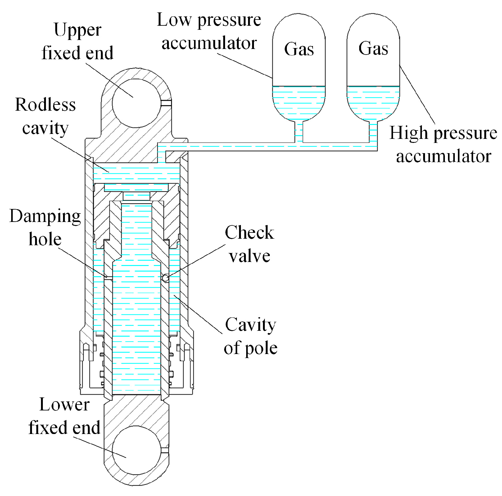
The main structure of the two-stage pressure hydro-pneumatic suspension is shown in Figure 1, which is mainly composed of a cylinder, piston rod, hydraulic oil, damping hole, one-way valve, high-pressure accumulator, low-pressure accumulator and other auxiliary accessories.
After the hydro-pneumatic suspension is excited by the road surface, in the suspension compression stroke, the piston rod moves up, and the pressure of the rodless cavity becomes larger. Some hydraulic oil enters the rod cavity from the rodless cavity through the check valve and the damping hole, and the other part of the hydraulic oil enters the accumulator. When the pressure of the rodless chamber is less than the opening pressure of the high-pressure accumulator, only the low-pressure accumulator works; when the pressure of the rodless cavity is greater than the opening pressure of the high-pressure accumulator, the high- and low-pressure accumulators work together. In the process of suspension rebound, the pressure of the rod cavity becomes larger, the check valve is closed, the hydraulic oil flows from the rod cavity into the rodless cavity through the damping hole, resulting in a large damping force, and the hydraulic oil in the accumulator flows to the rodless cavity under the action of gas pressure.

2.2. Theoretical Analysis of Two-Stage Pressure Hydro-Pneumatic Suspension Characteristics

2.2.1. Oil Cylinder Pressure

Assuming that the hydraulic oil is incompressible, when only the low-pressure accumulator works, the piston displacement is x1, and the gas volume in the low-pressure accumulator is:
V L = V 1 A x 1
In Equation (1), V1 represents the initial volume of the low-pressure accumulator when the suspension is in equilibrium. A represents the area of the piston rod. According to Boyle’s law p 1 V 1 r = p L ( V 1 A x 1 ) r , the cylinder pressure is:
p L = p 1 V 1 r ( V 1 A x 1 ) r
In Equation (2), p1 represents the initial pressure of the low-pressure accumulator when the suspension is in equilibrium. r represents the gas polytropic index. When the high- and low-pressure accumulators work together, assuming that the piston displacement is x2, the gas volume change in the low-pressure accumulator is Δ V 1 , and the gas volume change in the high-pressure accumulator is Δ V 2 , the total change in the suspended gas is:
Δ V = Δ V 1 + Δ V 2 = A x 2
Then, the gas change equations of the high- and low-pressure accumulators are obtained as follows:
p 1 V 1 r = p H ( V 1 Δ V 1 ) r p 2 V 2 r = p H ( V 2 Δ V 2 ) r
In Equation (4), p2 and V2 are respectively expressed as the initial pressure and initial volume of the high-pressure accumulator when the suspension is in equilibrium. Combined with Equations (3) and (4), the cylinder pressure of the high- and low-pressure accumulators working together is obtained:
p H = V 1 p 1 r + V 2 p 2 r V 1 + V 2 A x 2 r
The cylinder pressure at any time is:
p t = p 1 V 1 r ( V 1 A x 1 ) r p t < p 2 V 1 p 1 r + V 2 p 2 r V 1 + V 2 A x 2 r p t p 2
In order to facilitate the theoretical derivation and analytical analysis, the pressure equation of the combined accumulator shown in Equations (5) and (6) adopts the isothermal process approximation, and the complete multi-process gas state equation has been realized by the numerical method in the AMESim simulation model.

2.2.2. Body Vertical Acceleration

From Equation (6), the suspension output force is:
F = A p 1 V 1 r ( V 1 A x 1 ) r p t < p 2 A V 1 p 1 r + V 2 p 2 r V 1 + V 2 A x 2 r p t p 2
Combined with Newton‘s second law, the vertical acceleration of the body is obtained by Equation (7) as follows:
a = A p 1 V 1 r m ( V 1 A x 1 ) r p t < p 2 A m V 1 p 1 r + V 2 p 2 r V 1 + V 2 A x 2 r p t p 2
In Equation (8), m denotes the mass of the spring.

2.2.3. Damping Force

The suspension damping force is mainly generated when the hydraulic oil flows through the damping hole and the one-way valve. The effective throttling area of the damping hole and the check valve is Az and Ad, respectively; the flow coefficient is Cz and Cd, respectively; the suspension dynamic stroke symbol function is s i g n ( x ˙ ) ; and the upward is positive and the downward is negative. According to the orifice throttling formula Q = C A 2 Δ p ρ , the flow rate can be obtained as follows:
Q = C z A z + C d A d 1 2 + 1 2 s i g n ( x ˙ ) 2 Δ p ρ
In Equation (9), ρ represents the hydraulic oil density and Δ p represents the pressure difference between the rod cavity and the rodless cavity. According to the parameters of the check valve, the effective throttling area Ad can be calculated:
A d = π d 4 2 σ R 2 d 4 2 4 + σ 2 / R 2 + 2 σ R 2 d 4 2 4 + σ 2 2
In Equation (10), σ represents the opening of the check valve, d4 represents the diameter of the check valve, and R represents the radius of the ball valve. According to Equation (10), the throttling area is affected by the diameter of the check valve, which affects the suspension performance. From the motion relationship between the cylinder and the piston rod, the flow Q can be obtained:
Q = A 1 x ˙
In Equation (11), A1 is the area of the rod cavity, which indicates the relative velocity of the piston. The pressure difference between the rodless cavity and the rod cavity can be obtained by Equations (9) and (11):
Δ p = s i g n ( x ˙ ) ρ A 1 2 x ˙ 2 / 2 C z A z + C d A d 1 2 + 1 2 s i g n ( x ˙ ) 2
Therefore, the damping force is:
F z = A 1 Δ p = s i g n ( x ˙ ) ρ A 1 3 x ˙ 2 / 2 C z A z + C d A d 1 2 + 1 2 s i g n ( x ˙ ) 2
It can be seen from Equation (13) that the rod cavity area has a cubic relationship with the damping force, which has the most significant effect on it. The relative velocity of the piston, the throttle area and the flow coefficient of the damping hole and the one-way valve are quadratic, and the influence on the damping force is also very significant. The hydraulic oil density is a linear term, and the influence on the damping force is relatively weak. When the suspension size is determined, the damping force only depends on the relative motion speed between the piston and the cylinder.

3. Analysis of Hydro-Pneumatic Suspension Characteristics Under Dynamic Load Excitation

3.1. Hydro-Pneumatic Suspension Excitation Model Construction

The dynamic response of a hydro-pneumatic suspension is mainly determined by the structural parameters. During the dynamic motion of the vehicle, the hydro-pneumatic suspension plays a key role in buffering and reducing vibration caused by road excitation. In order to explore the influence of the change in hydro-pneumatic suspension parameters on the buffering effect, this paper establishes a two-stage pressure hydro-pneumatic suspension impact model under the excitation of ground obstacles. Taking a certain type of wide-body dump truck as an example, the main parameters of the hydro-pneumatic suspension are shown in Table 1.
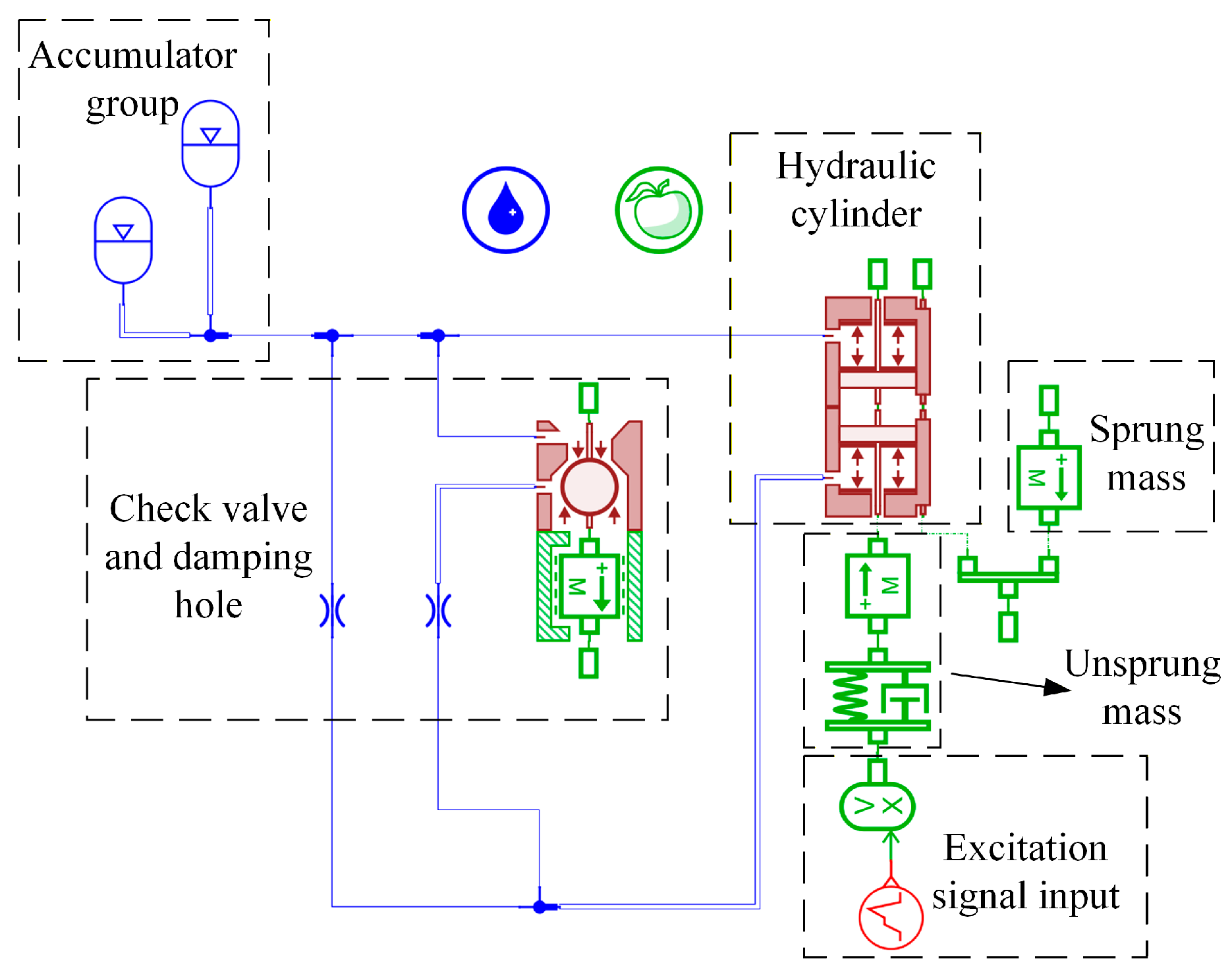
The sampling frequency of the data acquisition system used in this test is only 20 Hz. In order to avoid the loss of dynamic response data due to the limitation of sampling frequency and ensure the integrity and analysis of vibration signals, the vehicle speed is set to 0.23 m/s. Subsequently, higher-sampling-frequency equipment will be used to carry out experimental research close to the actual vehicle speed. Based on the structural parameters of the two-stage pressure hydro-pneumatic suspension shown in Table 1, an AMESim model of a hydro-pneumatic suspension under the excitation of road obstacles is built, as shown in Figure 2.
The sprung mass is simulated by the MAS002 component sub-model. The hydraulic cylinder model with a moving cylinder is established by the BRP18 sub-model. The unsprung mass is constructed based on the SD0000 A sub-model and MAS002 sub-model, and the elastic and damping energy absorption processes of the tire are considered. The UD00 sub-model and XVLC01 sub-model are used to realize the excitation input of road obstacles. The one-way valve is constructed by the MAS005RT sub-model and BAP24 sub-model. The HYDORF0 sub-model is used to simulate the damping hole. Ignore the liquid leakage of the hydraulic cylinder and other hydraulic components.

3.2. The Influence of Structural Parameters on the Dynamic Response of Hydro-Pneumatic Suspension

Three kinds of road obstacle models are used to simulate different forms of excitation input, and the dynamic response of the hydro-pneumatic suspension under different excitations is analyzed [19]. The three road obstacle models are shown in Figure 3.
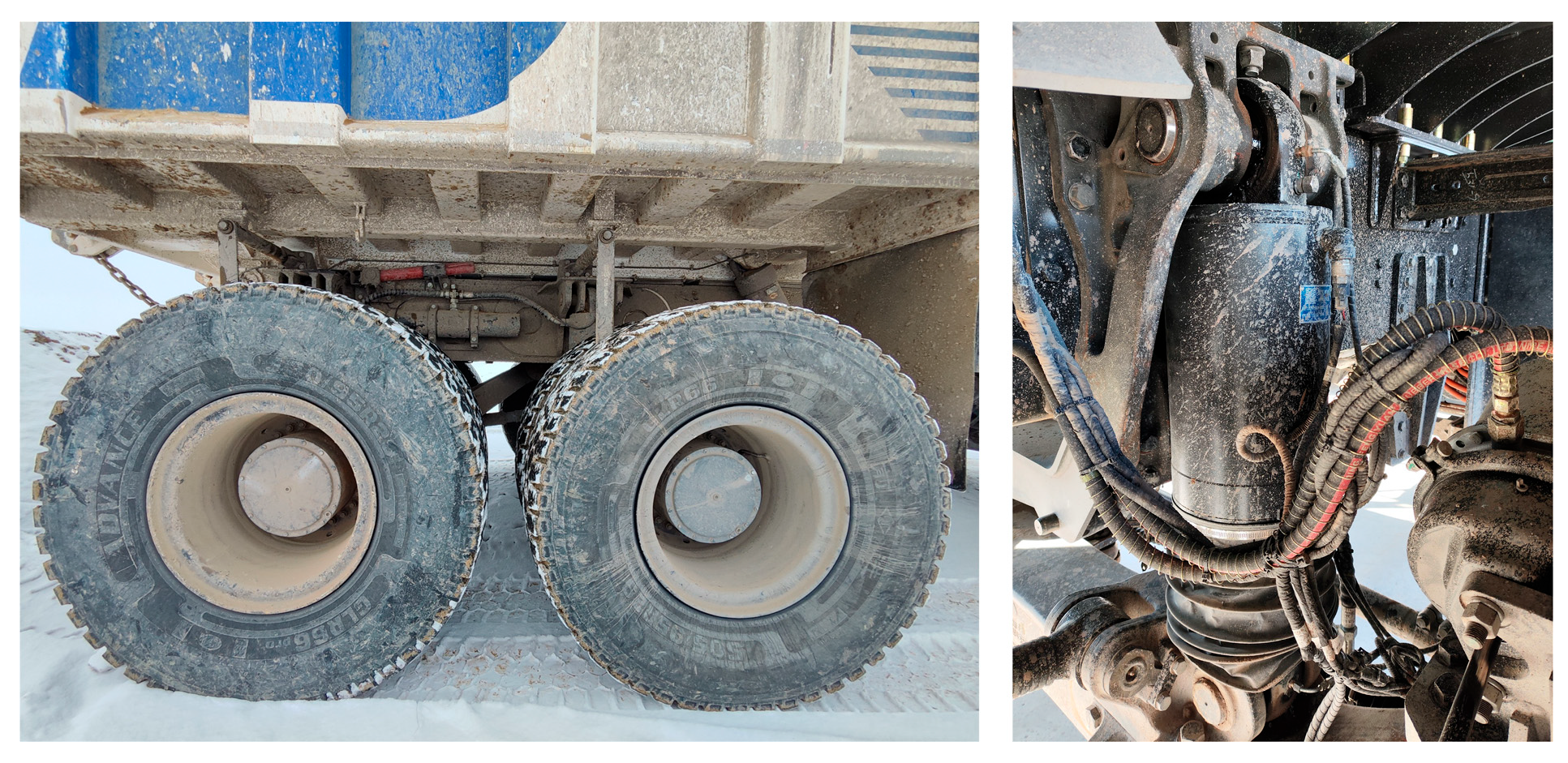
In order to verify the accuracy of the built AMESim model, a pressure sensor is installed on the two-stage pressure hydro-pneumatic suspension, and the pressure data of the suspension is obtained by the data acquisition instrument. The two-stage pressure hydro-pneumatic suspension and the pressure sensor are shown in Figure 4.
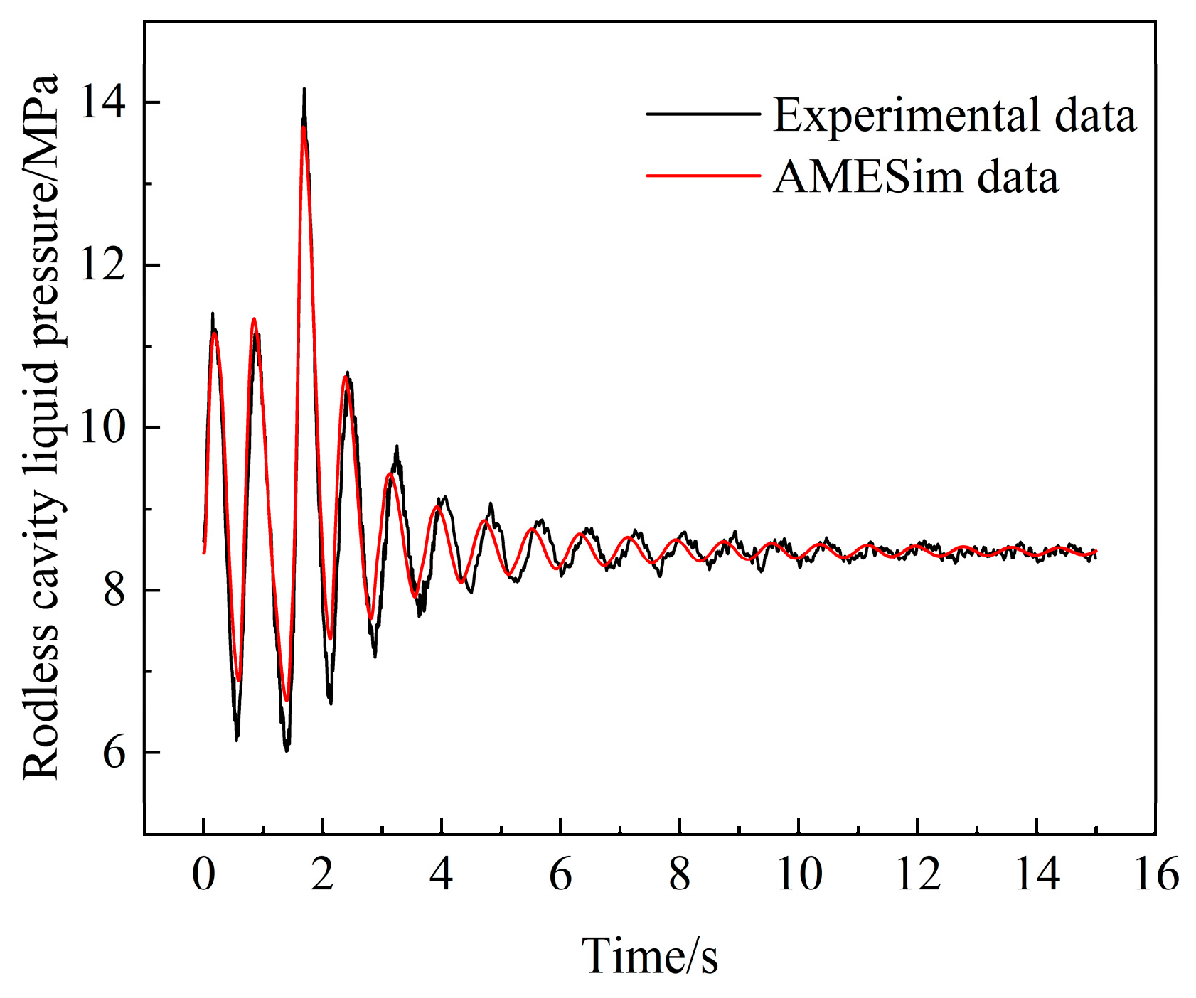
The trapezoidal obstacle in Figure 3a is selected as the excitation condition of the experiment and simulation. In this experiment, the deceleration zone is used to simulate the excitation effect of the trapezoidal contour obstacle on the vehicle, so as to reproduce the typical bumpy conditions of the non-paving road surface in the open-pit mine. The test object is a pure electric driverless mine truck with a rated load of 91 tons. During the test, the vehicle maintains an idle speed of 1 km/h, which is close to the actual operating conditions such as low-speed inspection and fixed-point parking in the mining area. The output data and experimental data of the two-stage pressure hydro-pneumatic suspension simulation model are compared. The comparison results of the liquid pressure between the two are shown in Figure 5.
It can be seen from Figure 5 that the trend of AMESim simulation data is basically the same as that of experimental data. The liquid pressure fluctuates after being excited, and then tends to be stable after oscillation attenuation. The peak pressure of simulation data is 13.71 MPa, and the peak pressure of experimental data is 14.17 MPa. The error is 3.24%, indicating the accuracy of the model.
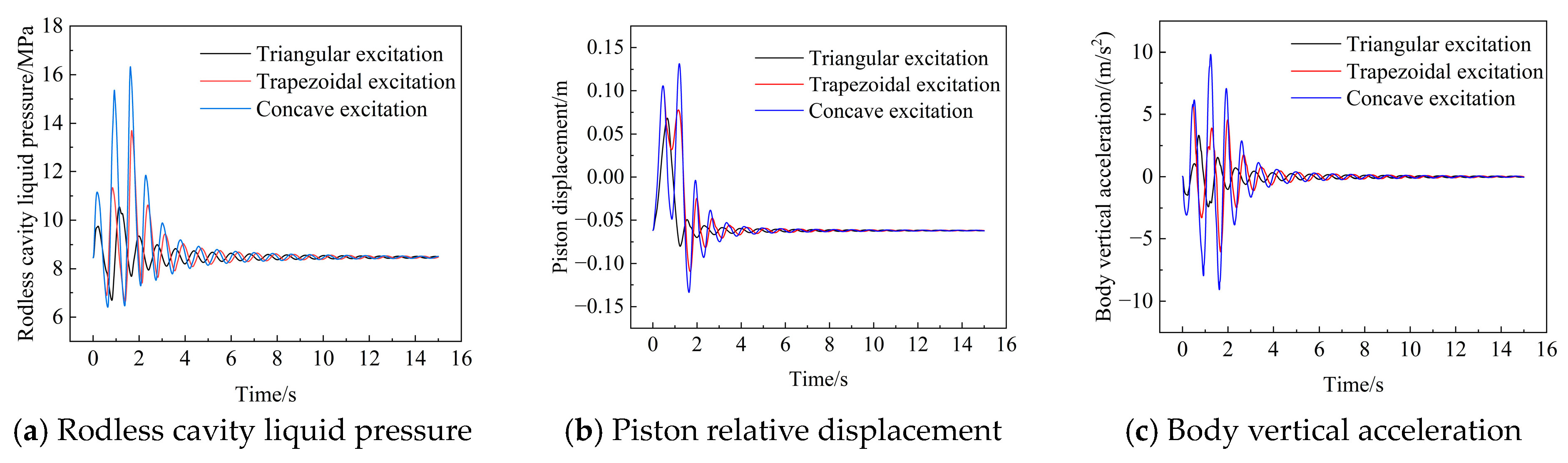
The obstacle types in Figure 3 are input into the UD00 sub-model, respectively. The simulation time is set to 15 s and the sampling interval is 0.001 s. The dynamic response of the hydro-pneumatic suspension under three excitations is shown in Figure 6.
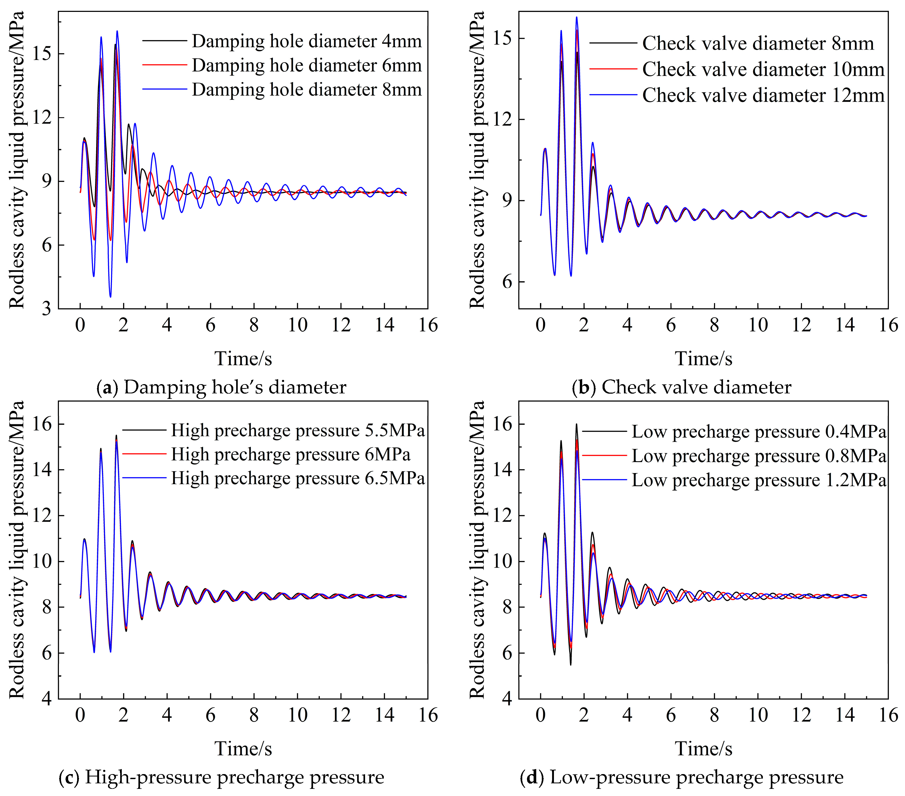
It can be seen from Figure 6 that concave excitation has the most significant effect on the dynamic performance of the suspension, so concave excitation is used to study the suspension performance. In order to analyze the influence of various parameters of the hydro-pneumatic suspension on its performance, a single-factor test was carried out with the diameter of the damping hole, the diameter of the check valve, the precharging pressure of the high-pressure chamber, and the precharging pressure of the low-pressure chamber as variables to explore the response characteristics of the above parameters to the liquid pressure during the hydro-pneumatic suspension excitation process [20,21]. The single-factor experimental design is shown in Table 2.
Figure 7 shows the change trend of the pressure in the rodless cavity under the condition of four parameters changing. It can be seen from the diagram that the structural parameters and the initial inflation pressure of the accumulator have a significant effect on the suspension performance. Among them, the diameter of the check valve is positively correlated with the peak value of the liquid pressure in the rodless cavity; the high-pressure precharge pressure and low-pressure precharge pressure of the accumulator are negatively correlated with the peak value of liquid pressure in rodless cavity. The diameter of the damping hole has a nonlinear effect on the peak pressure of the rodless cavity. When the diameter of the damping hole is 8 mm, the peak pressure of the liquid during the excitation process can reach 16.08 MPa, and the maximum fluctuation amplitude of the liquid is 12.54 MPa. When the diameter of the damping hole is 4 mm, the peak pressure of the liquid is 15.45 MPa, and the maximum fluctuation amplitude of the liquid is 6.91 MPa. It can be seen that the diameter of the damping hole has a significant effect on the liquid pressure. Therefore, it is very important to analyze the interaction between parameters and solve the optimal parameter combination to improve the hydro-pneumatic suspension’s performance.

4. Multi-Objective Parameter Optimization of Two-Stage Pressure Hydro-Pneumatic Suspension

From the results of Section 3.2, it can be seen that the two-stage pressure hydro-pneumatic suspension parameters have significant sensitivity to its dynamic response. Due to the complexity of the liquid shock response mechanism caused by the change in structural parameters, it is difficult to establish a complete theoretical model to describe the influence of each parameter on its dynamic response. Due to the high cost of obtaining data through experiments, this paper mainly focuses on simulation analysis to evaluate the influence of hydro-pneumatic suspension parameters on the peak pressure Pp, the maximum fluctuation amplitude Pa of liquid pressure and the maximum vertical acceleration Amax of the body. On this basis, based on the simulation results, the parameters are systematically analyzed and multi-objective optimization is carried out to achieve a comprehensive improvement of dynamic performance.

4.1. Study on the Dynamic Characteristics of Parameters Based on Response-Surface Method

The experimental design software was used for design and analysis. The BBD experimental method was selected. The design sub-type was randomized, the number of center points was 3, and the design model was quadratic. The diameter of the damping hole Dd, the diameter of the check valve Cd, the precharging pressure Hp of the high-pressure accumulator, and the precharging pressure Lp of the low-pressure accumulator are used as the design variable factors. The design factors and levels are shown in Table 3.
The experimental design is carried out according to the parameters in Table 3, and the experiment is carried out according to the design parameters. Some experimental schemes and results are shown in Table 4.
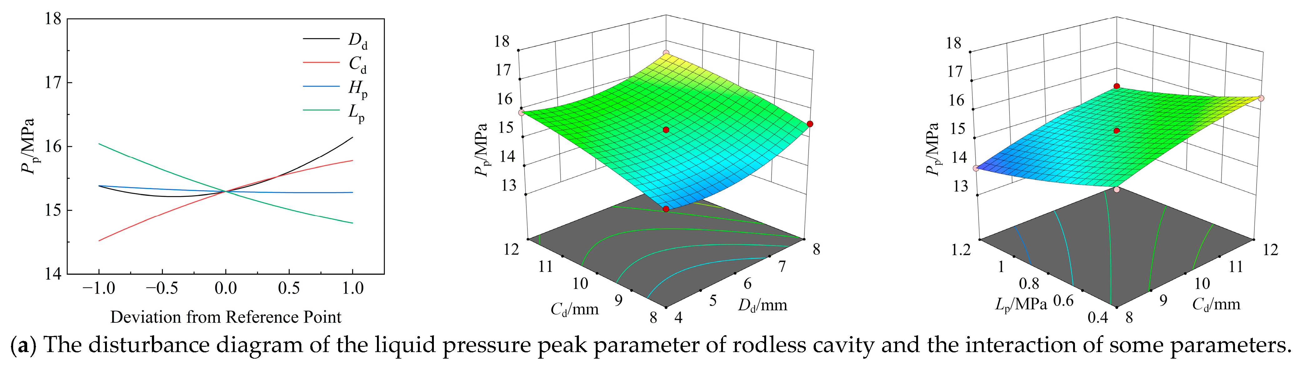
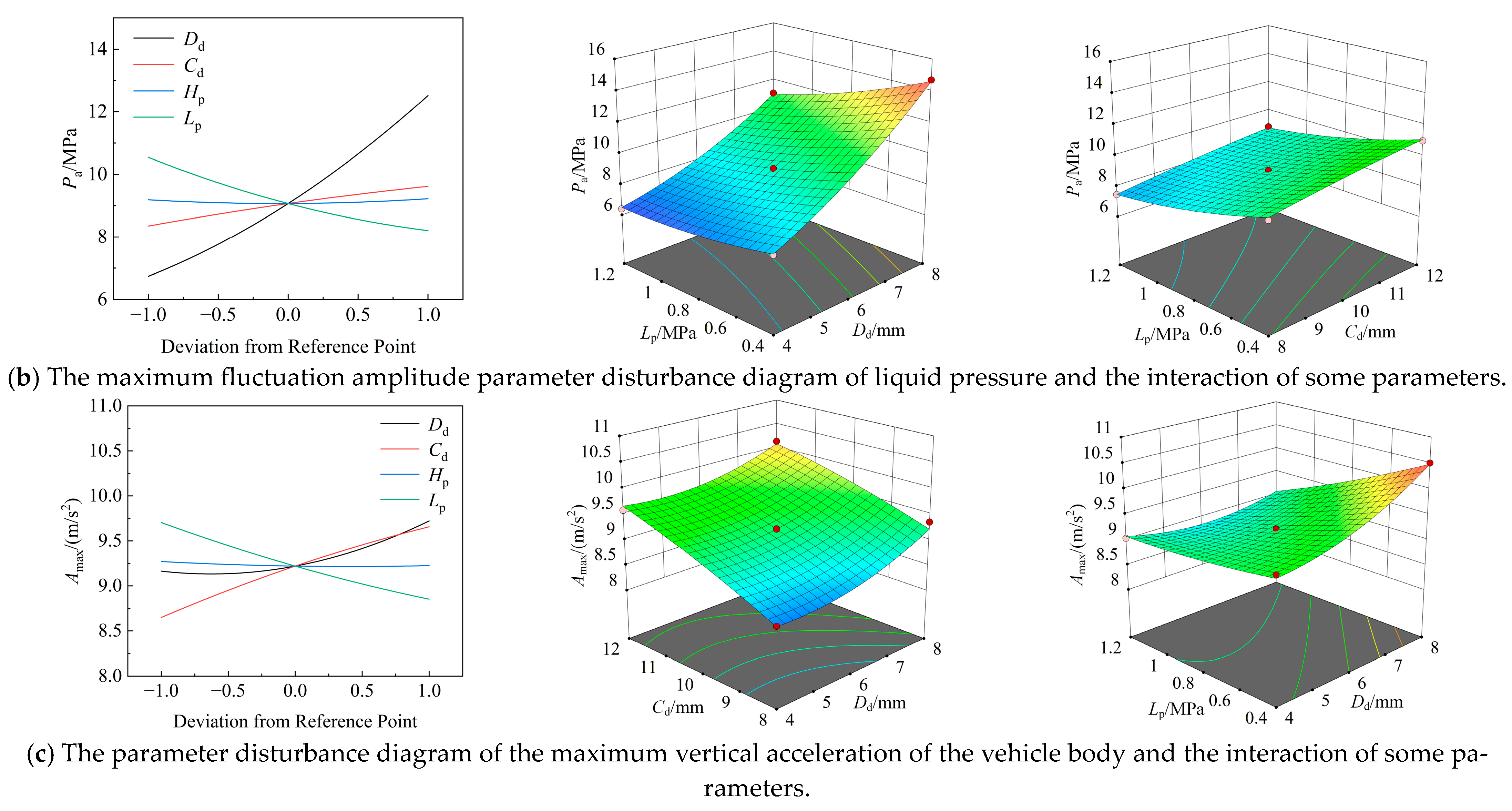
A goodness-of-fit test of the constructed response-surface model was carried out. The adjusted R2 corresponding to the peak liquid pressure, the maximum fluctuation amplitude of liquid pressure and the maximum vertical acceleration of the body were 0.9795, 0.9954 and 0.9469, respectively, which were all higher than 0.90, indicating that the established model has high fitting accuracy and good credibility and can accurately reflect the mapping relationship between various factors and optimization objectives. In order to explore the influence of parameter interaction on the peak liquid pressure Pp, the maximum fluctuation amplitude Pa of the liquid pressure and the maximum vertical acceleration Amax of the body, they are analyzed, respectively. Figure 8 shows the parameter perturbation diagram of each response and the influence of some parameter interactions on the response.
It can be seen from Figure 8a that the diameter of the check valve is positively correlated with the peak pressure. The diameter of the damping hole has a nonlinear relationship with the peak pressure. As the diameter of the damping hole increases, the peak pressure first decreases and then increases. The precharging pressure of the high-pressure accumulator and the precharging pressure of the low-pressure accumulator are negatively correlated with the peak pressure. Among them, the response of the three factors except the precharging pressure of the high-pressure accumulator is more significant. It can be seen from the interaction diagram between the parameters that the damping hole diameter and the check valve diameter have a high nonlinear response to the peak pressure. It can be seen from Figure 8b that the diameter of the damping hole and the diameter of the check valve are positively correlated with the maximum fluctuation amplitude of the pressure. Among them, the diameter of the damping hole has the most significant effect, in the range of 4.5 mm to 5.5 mm, and the maximum fluctuation amplitude of pressure shows an upward trend. This is mainly because as the diameter of the damping hole increases, its damping effect is weakened and the superposition of pressure waves is increased. The precharge pressure of the high-pressure accumulator has no significant effect on the maximum fluctuation amplitude of the pressure. The precharge pressure of the low-pressure accumulator is negatively correlated with the maximum fluctuation amplitude of the pressure. From the interaction diagram between the parameters, it can be seen that the interaction between the diameter of the damping hole and the precharging pressure of the low-pressure accumulator, the diameter of the one-way valve and the precharging pressure of the low-pressure accumulator on the maximum pressure fluctuation amplitude is almost linear. It can be seen from Figure 8c that the damping hole diameter has a nonlinear relationship with the maximum vertical acceleration of the vehicle body, in the range of 4.5 mm to 5.5 mm, and the maximum vertical acceleration of the vehicle body first decreases and then increases. The diameter of the check valve is positively correlated with the maximum vertical acceleration of the body. The precharging pressure of the low-pressure accumulator is negatively correlated with the maximum vertical acceleration of the vehicle body. From the interaction diagram between the parameters, it can be seen that the interaction between the diameter of the damping hole and the diameter of the one-way valve, the diameter of the damping hole and the precharge pressure of the low-pressure accumulator on the maximum vertical acceleration of the vehicle body is nonlinear.

4.2. Multi-Objective Parameter Optimization

In order to reduce the peak value of the liquid pressure, reduce the maximum fluctuation amplitude of the liquid pressure and reduce the maximum vertical acceleration of the vehicle body, the diameter of the damping hole, the diameter of the check valve, the precharge pressure of the high-pressure accumulator and the precharge pressure of the low-pressure accumulator are solved by multi-objective optimization. The ranges of the damping hole diameter, check valve diameter, precharge pressure of the high-pressure accumulator and precharge pressure of the low-pressure accumulator are 4 mm~8 mm, 4 mm~8 mm, 5.5 Mpa~6.5 Mpa, and 0.4 Mpa~1.2 Mpa, respectively. The parameter optimization model is as follows:
Min   P p D d , C d , H p , L p P a D d , C d , H p , L p A max ( D d , C d , H p , L p )   S . t .   4   mm D d 8   mm 4   mm C d 8   mm 5.5   MPa H p 6.5   MPa 0.4   MPa L p 1.2   MPa
The experimental results of the response surface are fitted, and the prediction models of the peak value of liquid pressure, the maximum fluctuation amplitude of liquid pressure and the maximum vertical acceleration of the vehicle body are obtained as follows:
P p = 19.88167 1.64542 D d + 1.06875 C d 2.39167 H p + 2.46458 L p 0.01625 D d C d + 0.16 D d H p 0.44375 D d L p + 0.0075 C d H p + 0.046875 C d L p 0.5125 H p L p + 0.116146 D d 2 0.036979 C d 2 + 0.138333 H p 2 + 0.778646 L p 2
P a = 23.70167 1.6125 D d + 0.653333 C d 7.11667 H p + 8.59167 L p + 0.0075 D d C d + 0.32 D d H p 0.775 D d L p + 0.005 C d H p + 0.0125 C d L p 1.675 H p L p + 0.140208 D d 2 0.021042 C d 2 + 0.543333 H p 2 + 1.91146 L p 2
A max = 14.91917 1.18167 D d + 0.6525 C d 2.36 H p + 1.3625 L p 0.0175 D d C d + 0.185 D d H p 0.353125 D d L p + 0.0025 C d H p + 0.03125 C d L p 0.2 H p L p + 0.055729 D d 2 0.016771 C d 2 + 0.111667 H p 2 + 0.361979 L p 2
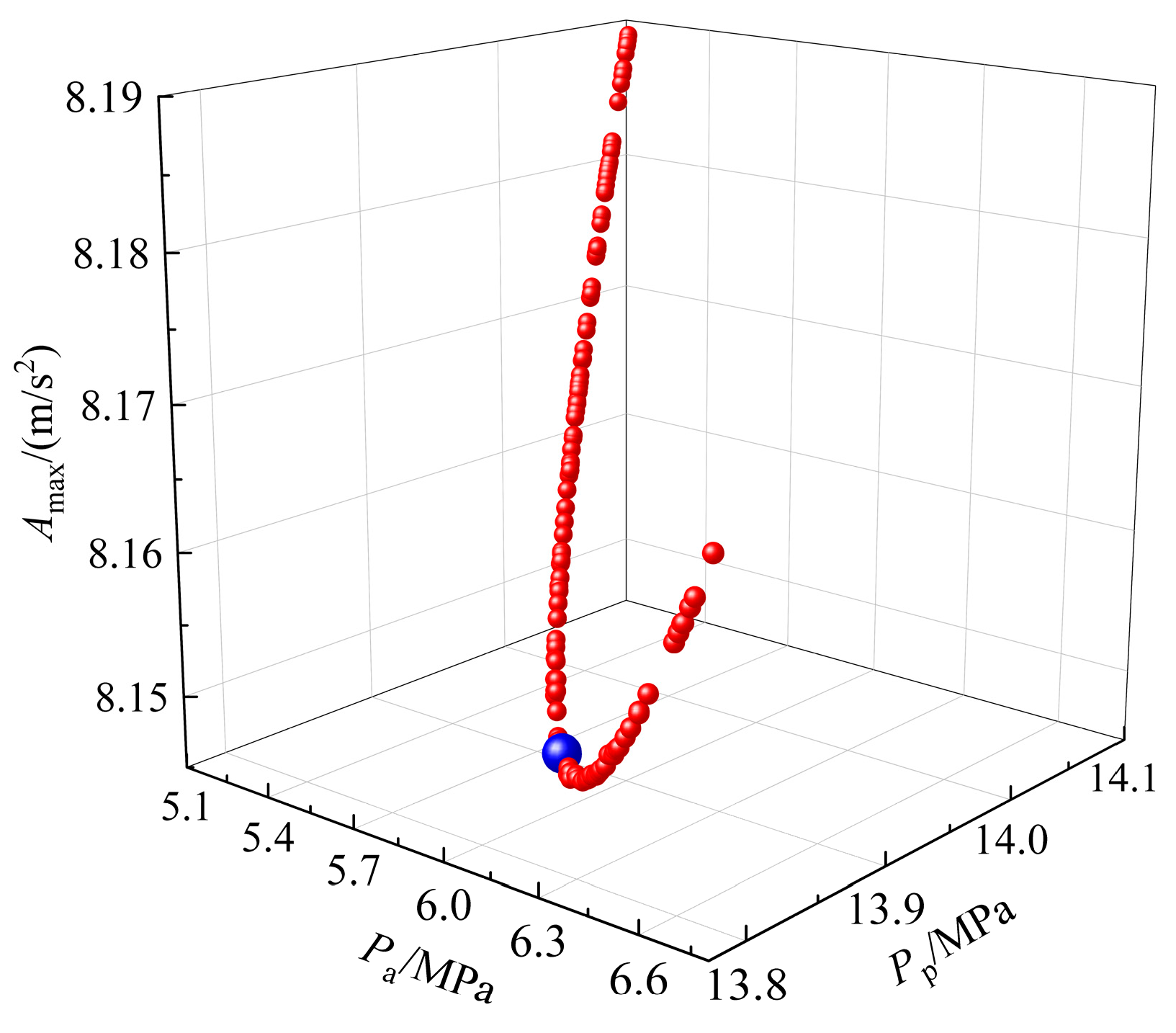
The multi-objective particle swarm optimization algorithm is used to solve Equation (14)’s parameter optimization model [22]. The objective function is Equations (15)–(17), the population number is set to 200, the archive number is set to 100, the inertia weight is set to 0.5, the repeated attenuation rate is set to 0.99, the learning factor is set to 2, and the number of iterations is set to 500. The Pareto solution set is obtained as shown in Figure 9.
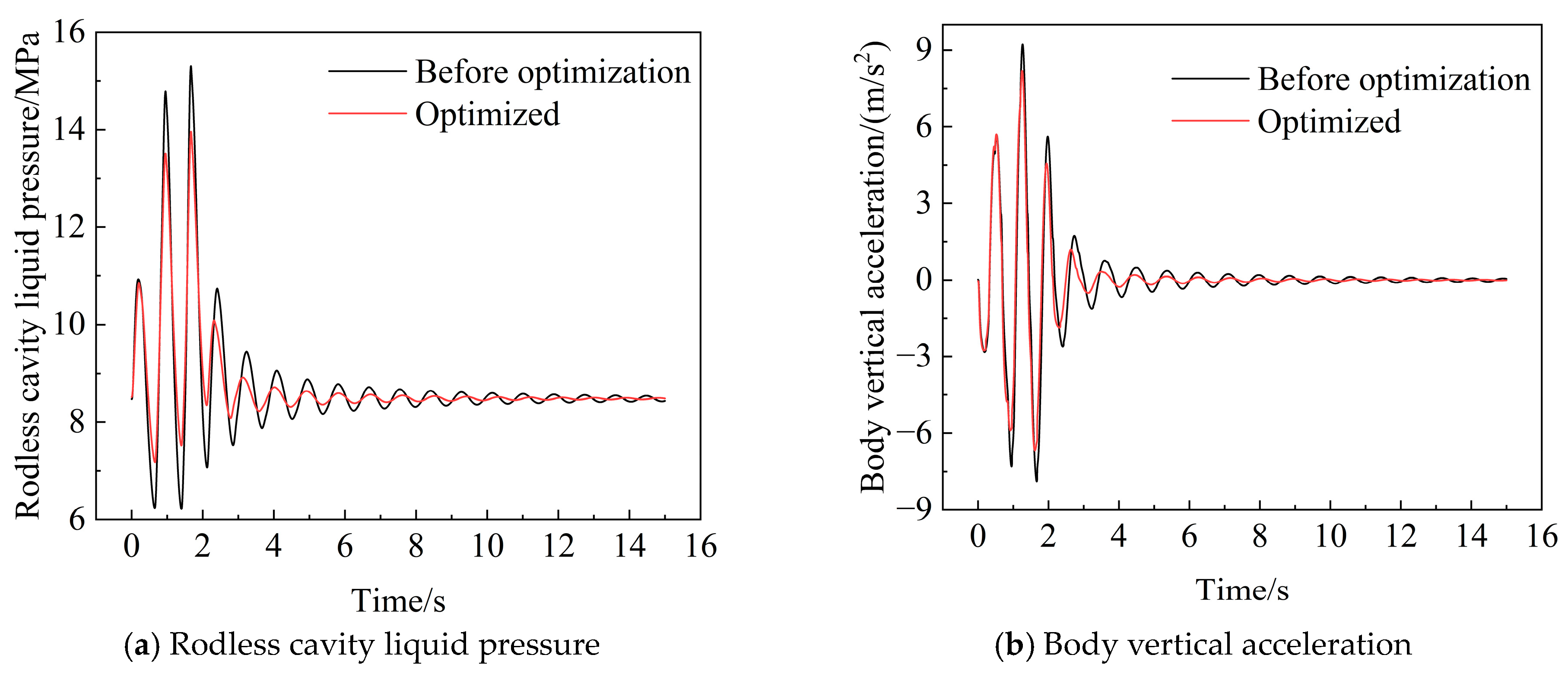
In the process of selecting the optimal solution, the strategy of priority weight is adopted for decision-making; the maximum vertical acceleration of the vehicle body is given sub-priority, while the peak value of the liquid pressure and the maximum fluctuation amplitude of the liquid pressure are given priority. The optimal solution is selected as shown in the blue point in Figure 9. The parameters corresponding to the optimal solution are Dd = 4.8102 mm, Cd = 8.005 mm, Hp = 6.493 MPa, and Lp = 1.2 MPa. Considering the standard size of the existing workpiece and the difficulty of processing, the above parameters are rounded nearby, and finally determined as Dd = 5 mm, Cd = 8 mm, Hp = 6.5 MPa, and Lp = 1.2 MPa. The obtained optimal parameters are input into the AMESim excitation model of the hydro-pneumatic suspension in Figure 2. The excitation form is concave excitation, and other parameters remain unchanged, which is shown in Figure 10 with the dynamic performance before optimization.
It can be seen from Figure 10 that the extreme values of liquid pressure and vertical acceleration of the vehicle body after parameter optimization are significantly lower than those before optimization. The peak value of liquid pressure after optimization is 13.96 MPa, which is 8.76% lower than that before optimization. The maximum fluctuation amplitude of liquid pressure is 29.1% lower than that before optimization, and the maximum vertical acceleration of vehicle body is 11.7% lower than that before optimization. The above results show that the optimized parameters effectively suppress the vibration of the vehicle body caused by external excitation and alleviate the pressure fluctuation of the hydro-pneumatic suspension. The detailed data are summarized in Table 5.

5. Conclusions

Taking the two-stage pressure hydro-pneumatic suspension as the research object, its dynamic performance is explored through theoretical modeling and simulation analysis. Based on AMESim, the suspension model under different excitations was constructed. Firstly, the single-factor influence analysis was carried out, and then the response-surface method was used to reveal the interaction between parameters. Finally, the optimal parameter combination was obtained by a multi-objective optimization algorithm. The main conclusions are as follows:
(1)
The excitation of a concave road surface has the most significant influence on the dynamic characteristics of a hydro-pneumatic suspension. Continuous impact can easily cause superposition and large oscillation of hydraulic pressure fluctuation, which directly affects the stability of suspension and the safety of vehicle operation. The research results show that we should pay attention to the careful control and smoothing treatment of the severe concave pavement profile of the road in the mining area. The relevant conclusions can provide reference for the subsequent real vehicle road test and pavement operation and maintenance optimization.
(2)
The interactive responses of the damping orifice diameter and check valve diameter to pressure peak and body vertical acceleration exhibit high nonlinearity. Among all parameters, the damping orifice diameter exerts the most significant influence on the dynamic performance of a hydro-pneumatic suspension. When the damping orifice diameter is in the range of 4.5 mm to 5.5 mm, both the liquid pressure fluctuation amplitude and the body vertical acceleration remain at low levels, resulting in good vehicle ride comfort.
(3)
The parameter combination after multi-objective optimization can significantly improve the comprehensive performance of a hydro-pneumatic suspension. Under the same excitation conditions, the peak value of liquid pressure, the maximum fluctuation amplitude of pressure and the maximum vertical acceleration of the vehicle body are reduced by 8.76%, 29.1% and 11.7%, respectively, which effectively improves the ride comfort of heavy-duty vehicles and the working reliability of the suspension system. It has engineering application value for improving the operation stability and continuous operation efficiency of heavy equipment in mines.

Author Contributions

Conceptualization, G.C. and G.Z.; methodology, G.L.; validation, P.Z. and G.L.; formal analysis, L.X.; investigation, C.W., L.X. and Q.K.; resources, C.W., Q.K. and P.Z.; data curation, P.Z.; writing—original draft, L.X.; writing—review and editing, C.W.; supervision, G.C. and G.Z.; funding acquisition, Q.K. All authors have read and agreed to the published version of the manuscript.

Funding

This work was supported by the Key R&D project of Xinjiang Uygur Autonomous Region (2023B01006).

Data Availability Statement

The original contributions presented in this study are included in the article. Further inquiries can be directed to the corresponding author.

Conflicts of Interest

Authors Chuanxu Wan, Lu Xiao, Guolei Chen, Qingwei Kang, Peng Zhou, Gang Zhou have received research grants from Company Subsidiary of Tebian Electric Apparatus. The Subsidiary of Tebian Electric Apparatus had no role in the design of the study; in the collection, analyses, or interpretation of data; in the writing of the manuscript, or in the decision to publish the results.

References

  1. Jin, H.; Lei, X.; Zhou, X.; Nan, D. Ride comfort analysis of interconnected hydro-pneumatic suspension system of mine wide-body vehicle. J. Mech. Electr. Eng. 2024, 41, 1160–1169. [Google Scholar] [CrossRef]
  2. Liu, X.; Li, Y. Review of Research on Vehicle Hydro-PneumaticSuspension Technology. J. Southwest Jiaotong Univ. 2025, 60, 374–394. [Google Scholar] [CrossRef]
  3. Wang, L.; Zhao, B.; Li, D. Simulation of Hydro-pneumatic Suspension and Vehicle Dynamics System of Wide Body Truck for Mine. Chin. Hydraul. Pneum. 2020, 11, 158–163. [Google Scholar]
  4. Sang, Z.; Dong, M.; Zhao, K.; Gu, L. Study on Characteristics of the Dual-Chamber Hydro-Pneumatic Suspension. Trans. Beijing Inst. Technol. 2018, 38, 499–504. [Google Scholar]
  5. Zhao, H.; Zhang, B.; Zhang, N.; Peng, P.; Zheng, M. Modeling and control strategy for a height adjustable and anti-roll hydraulically interconnected suspension. J. Vib. Shock. 2018, 37, 202–209. [Google Scholar]
  6. Sha, L.; Zhang, H.; Chen, G. Research on Dynamic Characteristics of Oil and Gas Suspension Cylinder. IOP Conf. Ser. Mater. Sci. Eng. 2019, 493, 012041. [Google Scholar] [CrossRef] [Scilit]
  7. Liu, T.; Shi, Y.; Cao, C.; Qi, J.; Wang, X.; Jia, Y. Analysis of Influence of Different Gas Chamber Volume on Dynamic Characteristics of Hydro-pneumatic Spring. Chin. Hydraul. Pneum. 2021, 45, 82–88. [Google Scholar]
  8. Fang, Y.; Li, B. Effect Analysis of Parameters Change on Performance of Independent Hydro Pneumatic Suspension Based on AMESim. Mach. Tool Hydraul. 2017, 45, 133–138. [Google Scholar]
  9. Wang, X.; Chen, S. Design of Vehicle Twin Accumulator Hydro-Pneumatic Pneumatic Balanced Suspension. Trans. Beijing Inst. Technol. 2012, 32, 475–478. [Google Scholar]
  10. Li, Y.; Wang, Y.; Pang, W.; Ye, C.; Yang, C. Design and Simulation Analysis of Structure of Dual Air Chamber Hydro-pneumatic Suspension. Mach. Tool Hydraul. 2016, 44, 141–144. [Google Scholar]
  11. Ji, P. Simulation on Pressure Characteristics of Hydropneumatic Suspension with Single Acting Cylinder. Chin. Hydraul. Pneum. 2015, 66, 59–61. [Google Scholar] [CrossRef]
  12. Jia, H.; Zhu, Y. Influence of Damping Hole Diameter of Hydro Pneumatic Suspension on Driving Stability and Ride Comfort of Heavy Vehicle. J. Chongqing Univ. Sci. Technol. Nat. Sci. Ed. 2020, 22, 110–114. [Google Scholar] [CrossRef]
  13. Ma, Z.; Wu, Y. Influencing Factors on Dynamic Characteristic Analysis of Hydro-pneumatic Suspension Based on ADAMS /AMESim/Simulink. Mach. Tool Hydraul. 2017, 45, 30–37. [Google Scholar]
  14. Yuan, J.; Fan, J.; Zhou, Y.; Dou, H.; Song, F. Design of a Front Alxe Hydro-pneumatic Suspension with Controllable Stiffness and Damping. Mach. Tool Hydraul. 2019, 47, 135–141. [Google Scholar]
  15. Cheng, F.; Guo, J.; Xie, W.; Zhang, J. Characteristic Research of Hydro-pneumatic Suspension with Twostage Accumulator. Hydraul. Pneum. Seals 2017, 37, 67–72. [Google Scholar]
  16. Wang, G.; Wang, W.; Suo, X.; Du, T.; Liu, X. Effects of Structural Parameters on Dynamic Characteristics of Two-stage Pressure Hydro-pneumatic Suspension. Chin. Hydraul. Pneum. 2023, 47, 107–115. [Google Scholar]
  17. Cheng, X.; Gao, Q.; Liu, Z. Analysis on Damping Characteristics and Effect Factors of Single Chamber Hydro-pneumatic Spring. Chin. Hydraul. Pneum. 2016, 8, 95–101. [Google Scholar]
  18. Zhao, J.; Gu, Z.; Zhang, S. Research and Optimization on the Mechanical Property of Mining Dump Truck’s Hydro-pneumatic Suspension. J. Mech. Eng. 2015, 51, 112–118. [Google Scholar] [CrossRef] [Scilit]
  19. Zhihui, M.; Dao, G.; Kai, Z.; Yuejian, C.; Jinsong, Z. Unsupervised domain adaptation method for bearing fault diagnosis assisted by twin data under extreme sample scarcity. Mech. Syst. Signal Process. 2025, 239, 113359. [Google Scholar] [CrossRef] [Scilit]
  20. Jacob, S.; Trigell, E.M.; Mihaescu, M.; Åbom, M. Acoustic scattering in a small centrifugal compressor based on the use of linearized equations in a rotating frame. J. Sound Vib. 2023, 544, 117315. [Google Scholar] [CrossRef] [Scilit]
  21. Kubelwa, Y.D.; Swanson, A.G.; Papailiou, K.O.; Dorrell, D.G. On the Euler-Lagrange formalism to compute power line bundle conductors subject to aeolian vibrations. Mech. Syst. Signal Process. 2022, 163, 108099. [Google Scholar] [CrossRef] [Scilit]
  22. Men, Z.; Li, Y.; Gao, L.; Zhang, Z. Fault diagnosis method for railway wagon bearings under imbalanced dataset based on improved ACWGAN. Nonlinear Dyn. 2025, 113, 14935–14962. [Google Scholar] [CrossRef] [Scilit]
Figure 1. Structure diagram of two-stage pressure hydro-pneumatic suspension.
Processes 14 01215 g001
Figure 2. AMESim excitation model of hydro-pneumatic suspension.
Processes 14 01215 g002
Figure 3. Three types of road obstacles.
Processes 14 01215 g003
Figure 4. Two-stage pressure hydro-pneumatic suspension and pressure sensor.
Processes 14 01215 g004
Figure 5. Comparison of AMESim simulation and experimental data.
Processes 14 01215 g005
Figure 6. Dynamic response of hydro-pneumatic suspension under different excitations.
Processes 14 01215 g006
Figure 7. Pressure variation trend of rodless cavity under different parameter changes.
Processes 14 01215 g007
Figure 8. Parameter perturbation diagram and parameter interaction effect.
Processes 14 01215 g008aProcesses 14 01215 g008b
Figure 9. Pareto solution set and optimal solution selection.
Processes 14 01215 g009
Figure 10. Comparison of dynamic performance of hydro-pneumatic suspension before and after optimization.
Processes 14 01215 g010
Table 1. Main parameters of a two-stage pressure hydro-pneumatic suspension for a wide-body dump truck.
Inner Diameter of Cylinder/mmPiston Rod Outer Diameter/mmDamping Hole’s Diameter/mmOne-Way Valve Diameter/mmPrecharge Pressure of Low-Pressure Accumulator/MpaLow-Pressure Accumulator Volume/LPrecharge Pressure of High-Pressure Accumulator/MpaHigh-Pressure Accumulator Volume/LSprung Mass/kgUnsprung Mass/kgVehicle Speed/(m/s)
2201806100.86.863.422,00030000.23
Table 2. Single-factor experimental design.
VariableDamping Hole’s Diameter/mmCheck Valve Diameter/mmHigh-Pressure Precharge Pressure/MPaLow-Pressure Precharge Pressure/MPa
Damping hole diameter4~8 (2)1060.8
Check valve diameter68~12 (2)60.8
High-pressure precharge pressure6105.5~6.5 (0.5)0.8
Low-pressure precharge pressure61060.4~1.2 (0.4)
Table 3. Design factors and levels.
FactorLevel
−101
Dd/mm468
Cd/mm81012
Hp/MPa5.566.5
Lp/MPa0.40.81.2
Table 4. Design scheme and results of response-surface experiment.
StdRunDd/mmCd/mmHp/MPaLp/MPaPp/MPaPa/MPaAmax/(m/s2)
2116860.415.229.069.67
726105.51.215.019.038.61
27361060.815.39.229.07
646106.50.416.169.7211.18
23246861.213.988.267.47
16256126.50.815.719.69.67
1526686.50.814.48.558.34
42781260.816.5610.1413.08
Table 5. Comparison of dynamic response parameters of hydro-pneumatic suspension before and after optimization.
Pp/MPaPa/MPaAmax/(m/s2)
Before optimization15.309.079.22
Optimized13.966.438.14
Decrease percentage8.76%29.1%11.7%
Disclaimer/Publisher’s Note: The statements, opinions and data contained in all publications are solely those of the individual author(s) and contributor(s) and not of MDPI and/or the editor(s). MDPI and/or the editor(s) disclaim responsibility for any injury to people or property resulting from any ideas, methods, instructions or products referred to in the content.