Article

Nanobubble Processing Method for Improved Surface Properties of Recycled Carbon Fibre

1
Department of Aeronautics and Astronautics, The University of Tokyo, 7-3-1 Hongo, Bunkyo-ku, Tokyo 113-8656, Japan
2
School of Engineering, The University of Tokyo, 7-3-1 Hongo, Bunkyo-ku, Tokyo 113-8656, Japan
3
Department of Materials Science and Technology, Tokyo University of Science, 6 Chome-3-1 Niijuku, Katsushika-ku, Tokyo 125-8585, Japan
*
Author to whom correspondence should be addressed.
Processes 2026, 14(5), 749; https://doi.org/10.3390/pr14050749
Submission received: 5 January 2026 / Revised: 6 February 2026 / Accepted: 22 February 2026 / Published: 25 February 2026
(This article belongs to the Section Materials Processes)

Abstract

Recycled carbon fibres frequently exhibit degraded surface functionality owing to prior matrix removal processes, limiting their compatibility with contemporary epoxy resin systems. This study proposes a nanobubble-based surface treatment route designed to restore and enhance the surface characteristics of recycled carbon fibres without aggressive chemical oxidation. The study generated ozone and carbon dioxide nanobubbles in aqueous media and experimentally investigated the effects of nanobubble treatment on the surface properties and adhesive behaviour of recycled carbon fibres. Surface chemical changes were examined using X-ray photoelectron spectroscopy, which revealed an increase in oxygen-containing functional groups due to the nanobubble treatment, indicating improved surface polarity and potential for chemical interaction with epoxy networks. The practical effectiveness of the treatment was assessed via a pinhole pull-out test that served as an indirect measure of interfacial adhesion with epoxy resin, especially the combination of ozone nanobubbles and recycled carbon fibres. Notably, the nanobubble-treated recycled carbon fibres exhibited an increase in the adhesion compared with untreated recycled carbon fibres, rising from 84.5 ± 11.5 MPa to 138.5 ± 14.8 MPa, reflecting enhanced wetting behaviour and stronger fibre–matrix interfacial bonding. Overall, the proposed nanobubble processing route offers a mild, scalable, and environmentally favourable method for restoring surface reactivity in recycled carbon fibres, supporting their reintegration into high-performance composite applications.

1. Introduction

High-performance carbon fibre products such as carbon fibre reinforced plastics (CFRPs) have found widespread application across numerous industries in recent years. J. Zhang et al. estimated the amount of carbon fibre demand to be 333,000 tons in 2025 [1]. Beyond their traditional use in aerospace and luxury automotive sectors, virgin carbon fibre (vCF) products have become increasingly prevalent in everyday environments. As consumption continues to rise, the imperative for effective recycling and reuse strategies to make a circular society has grown correspondingly [2,3,4,5,6,7]. Furthermore, carbon fibre is inherently non-biodegradable; thus, from the perspective of Life Cycle Assessment (LCA), it is imperative to ensure both extended service life and the capacity for multiple recycling cycles. In particular, CFRPs exhibit exceptional fatigue resistance, making them well-suited for long-term structural applications. Consequently, significant research focus has been directed towards the establishment of robust recycling technologies to fully exploit these durable characteristics within a circular economy [8,9,10]. The current typical carbon fibre usage cycle is shown in Figure 1.
However, current recycling methodologies including pyrolysis, chemical decomposition, and mechanical clashing require substantial refinement to achieve optimal efficiency and sustainability [5,11,12,13,14]. Because reproducing CFRP with recycled carbon fibre (rCF) is strongly expected, rCF requires a suitable fibre length and non-damaged surface for keeping the high performance [15,16,17]. Surface modification represents a critical step in the recycling workflow, particularly for enabling the effective utilisation of rCF. In addition, appropriate surface treatment protocols are essential for establishing strong interfacial adhesion between fibres and resin matrices, thereby ensuring optimal mechanical performance [18,19]. Whilst conventional approaches include plasma treatment, chemical modification, coating application, and microwave processing [20,21,22,23,24], there is growing demand for environmentally friendly, cost-effective alternative approaches. Thus, this study proposes nanobubble technology as a promising next-generation sustainable alternative. The comparison of carbon fibre surface modification methodologies between conventional ones and ours is shown in Table 1.
As Table 2 shows, conventional methodologies are not so sustainable and environmentally friendly. Also, from a Life Cycle Assessment (LCA) perspective, nanobubble treatment is the most viable path towards a circular economy in the aerospace and automotive sectors. Therefore, if our study works well for the surface modification of carbon fibre, this should have a great advantage for the industry.
This nanobubble-based surface treatment process can be readily integrated into the cleaning stage of carbon fibre processing. Authors previously reported that ozone nanobubbles can change the cellulose crystalline structure to lose and be more sensitive to chemical reactions [25]. It presents a particularly attractive option, as both treatments could potentially be conducted simultaneously.
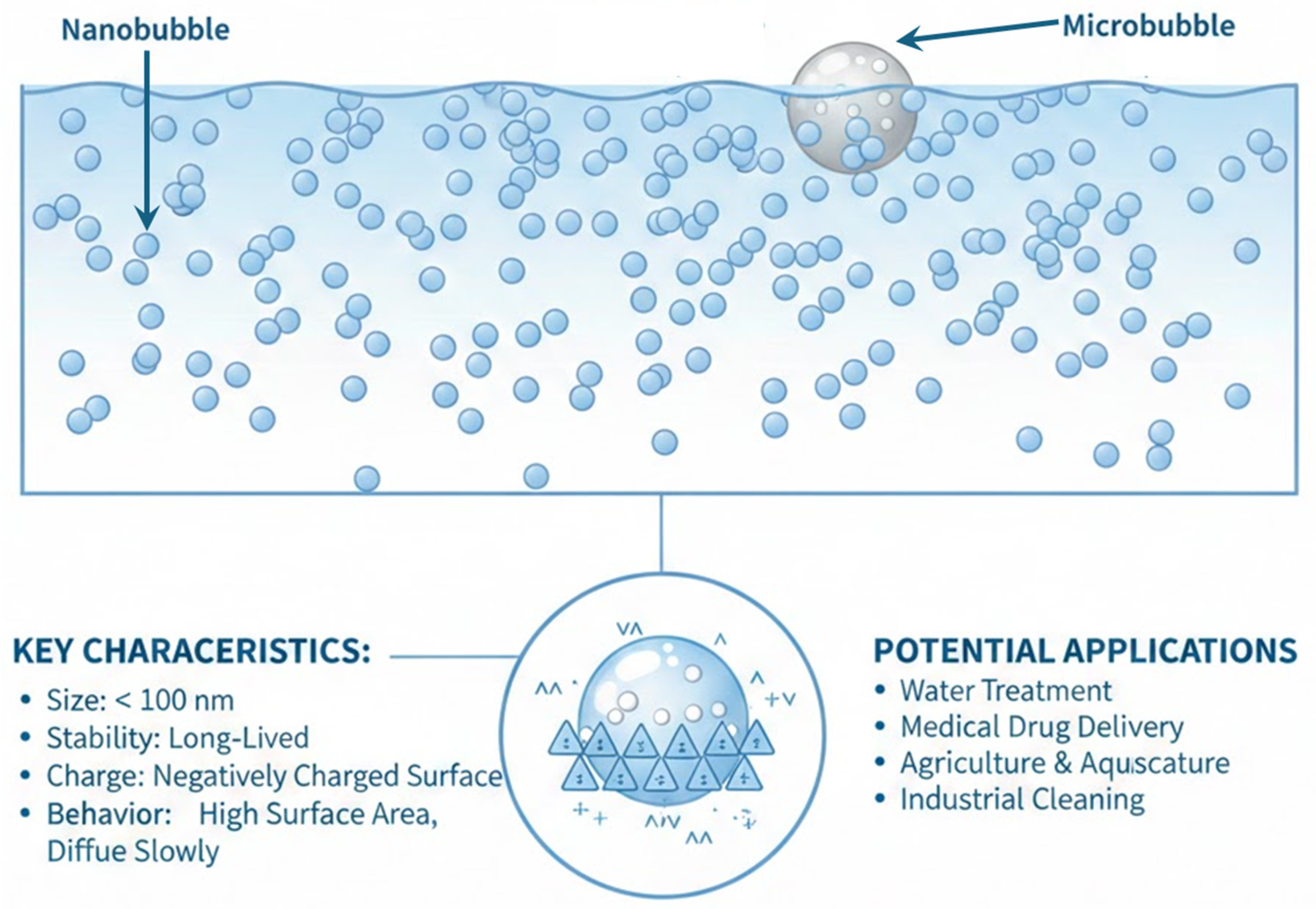
Nanobubbles—ultra-fine gaseous spheres generally measuring below 100 nm in diameter—have emerged as innovative solutions attracting considerable interest across diverse industrial sectors [26,27,28]. These structures exhibit distinctive physicochemical characteristics, including substantial specific surface area, remarkable temporal stability, superior gas dissolution capacity, negatively charged surface and potent oxidative properties [29,30,31]. These key points of nanobubbles are shown in Figure 2.
A particularly notable capability of nanobubbles is their efficacy in decomposing organic compounds. This phenomenon results from free radical species produced during bubble collapse, with various gases contributing to this process [32,33]. Additionally, this prolonged stability of nanobubbles enables sustained oxidative activity, maintaining reactive potential over considerably longer durations. The exceptionally small dimensions of these structures, having a high surface area-to-volume ratio, facilitate homogeneous treatment penetration, even within deeper material regions, whilst achieving remarkable efficiency at relatively low concentrations. Thus, the appropriate utilisation of nanobubble treatment leads to an alternative outstanding option for an ecofriendly sustainable method in terms of the low energy consumption and non-chemical use. In this study, the porous material diffusion approach was selected due to the moderate to high number density of nanobubbles, and it introduces gaseous species into liquids via ceramic materials featuring nanometre-scale apertures. Gas molecules traverse these pores, forming bubbles upon entering the liquid phase. The precise regulation of aperture dimensions and flow parameters enables accurate control over both the size distribution and concentration of the resulting nanobubbles. This technique proves especially valuable for producing monodisperse populations and finds frequent application where controlled gas dissolution is required.
Whilst extensive research has validated nanobubble efficacy in cleaning and purification applications [33,34,35,36], investigation into alternative uses remains relatively sparse. Published studies have documented enhanced seed germination in agricultural contexts [37] using nanobubbles, improved seafood preservation employing nitrogen and oxygen nanobubbles, and enhanced cooling performance in machining operations. However, there has been quite limited research on the material modification process, including carbon [18,38,39,40]. Within this context, the present research explores innovative surface modification strategies for especially carbon fibres or carbon materials, investigating the feasibility of nanobubble-mediated surface alteration. This study focuses on different gas nanobubbles, ozone (O3) nanobubbles and carbon dioxide (CO2) nanobubbles, and the two different types of carbon fibre, vCF and rCF, to reveal the difference in the effect of nanobubble mediation.

2. Materials and Methods

2.1. Materials

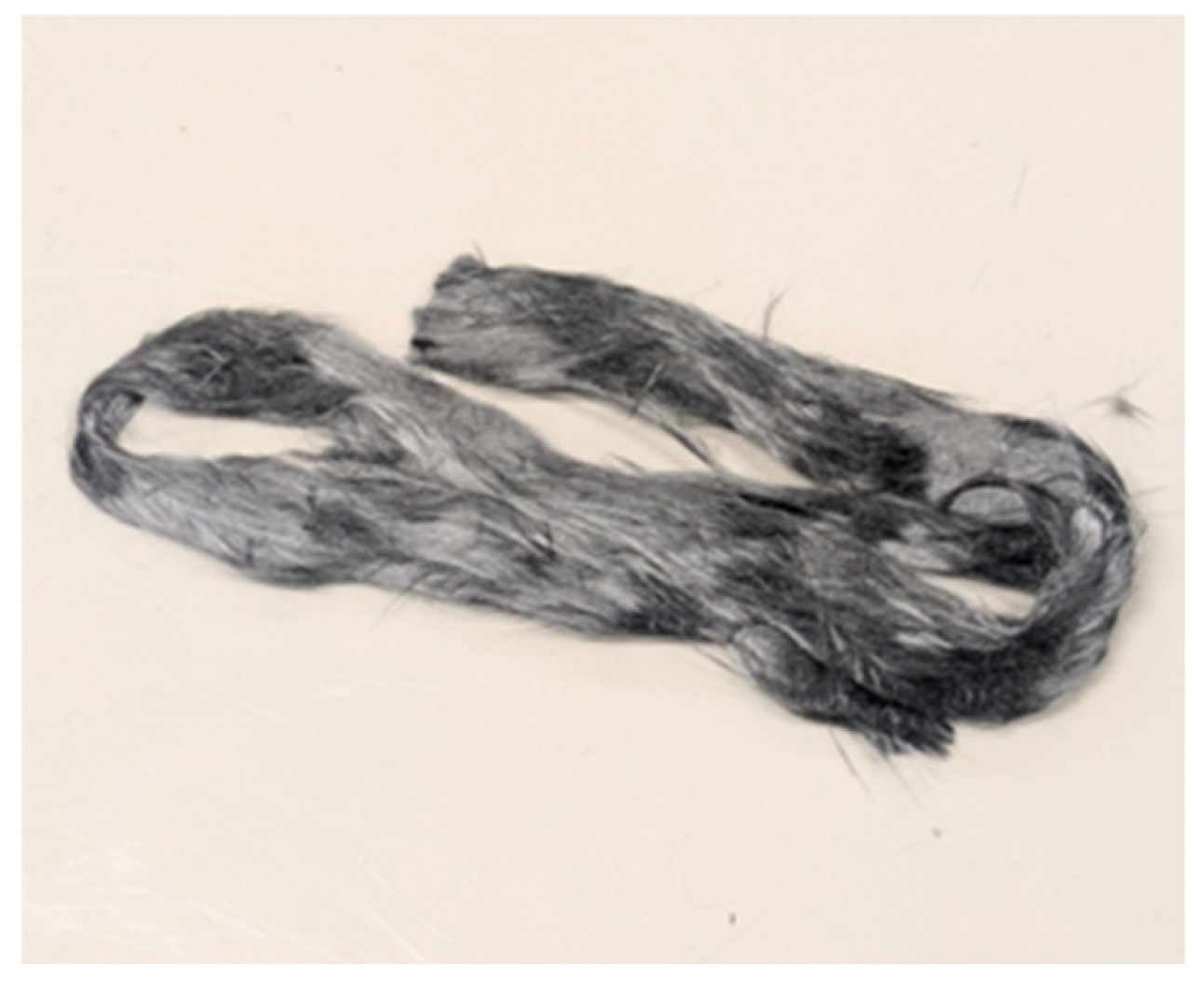
In this research all recycled carbon fibre (rCF) samples were donated from Tatsuta Boseki Co. Ltd. (Hyogo Prefecture, Japan). Their rCF, mainly composed of Toray T700, was from aerospace manufacture and to remove matrix resin from CFRP, chemical decomposed system was selected. rCF was provided as spun yarns that consisted of 5 mm length chopped fibres. The appearance of this rCF bundle is shown in Figure 3.
The virgin carbon fibre (vCF) of Toray T700 was purchased from Toray Co. (Tokyo, Japan). To remove the sizing agent, vCF was soaked into the acetone bath and washed and dried at room temperature. Epoxy resin jER828 (Mitsubishi Chemicals Co. Tokyo, Japan) was selected for the evaluation of the interfacial adhesion. This matrix resin was purchased from the manufacturer.

2.2. Preparation of Nanobubble-Treated Carbon Fibre

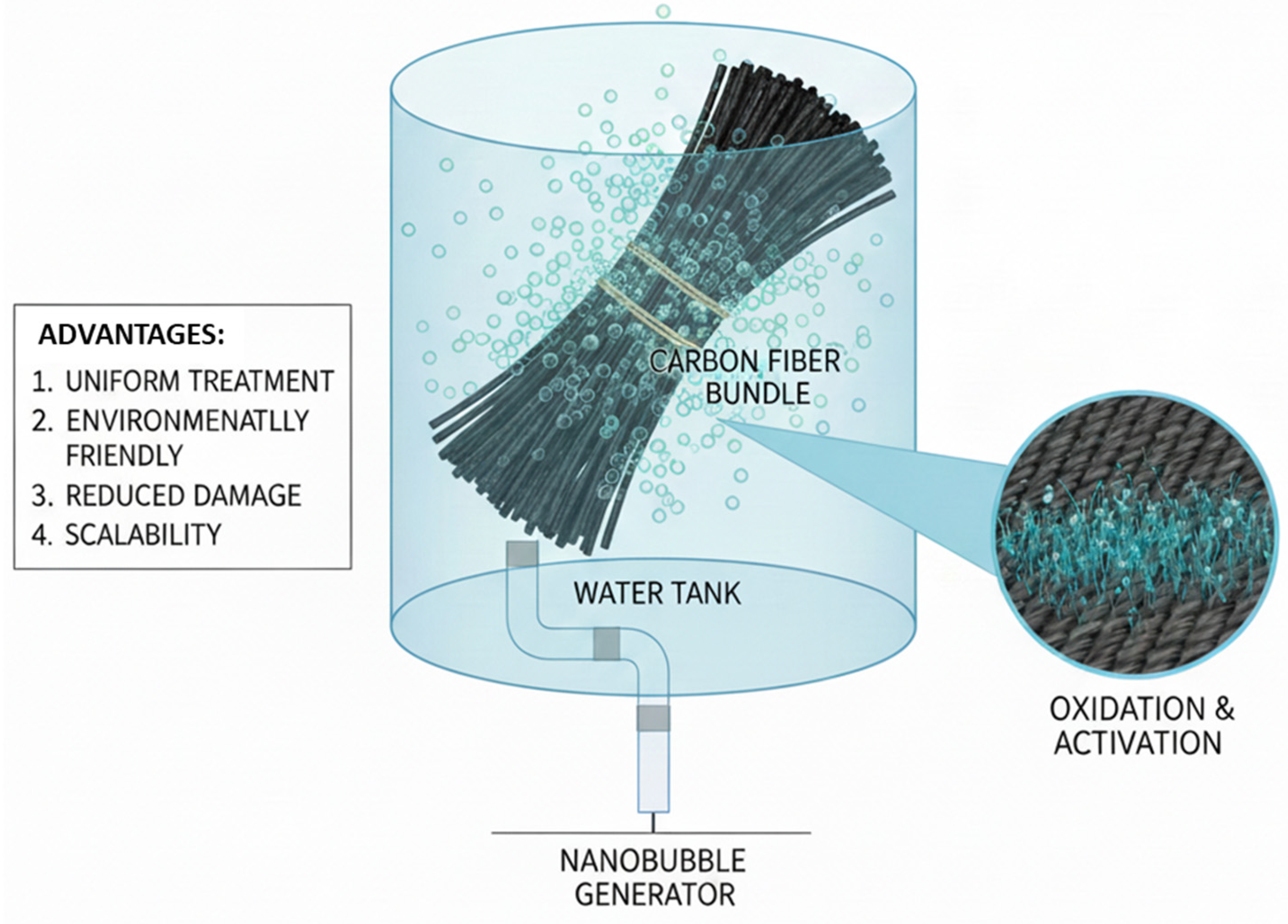
Multiple generation techniques exist for producing nanobubbles, each exploiting distinct physical and chemical mechanisms. The present investigation employs carbon-based porous materials for nanobubble generation. The concept image of nanobubble treatment is shown in Figure 4.
Nanobubble treatment of the studied carbon fibres (vCF and rCF) was performed by a nanobubble generator equipped with a ceramic with dimensions of φ9 mm diameter × 70 mm length (Anzaikantetsu Co, Ltd., Yokohama, Japan) and a water pump with a flow rate of 14 L/min. The nanobubble treatment was conducted under two different conditions using 0.5 g of carbon fibre (vCF or rCF) in 3 L of purified water (≦1 μS/cm). O3 nanobubbles (nanobubbles generated by O3 gas at 10 g/h) and CO2 nanobubbles (nanobubbles generated by CO2 gas with purity of ≧99.9%) were introduced into 3 L of circulating water continuously for 60 min at 23 °C. The median of nanobubble diameters and the number density of nanobubbles were 40.0 nm and 1.9 × 10⁸/mL for O3 nanobubbles and 14.0 nm and 3.7 × 10¹²/mL for CO2 nanobubbles respectively, as measured by Zetasizer Ultra (Malvern Panalytical, Ltd., Worcestershire, UK). After both nanobubble treatments, the treated carbon fibre was dried at room temperature overnight, and the effects of the treatment were evaluated.

2.3. Characterisation of Nanobubble-Treated Carbon Fibre

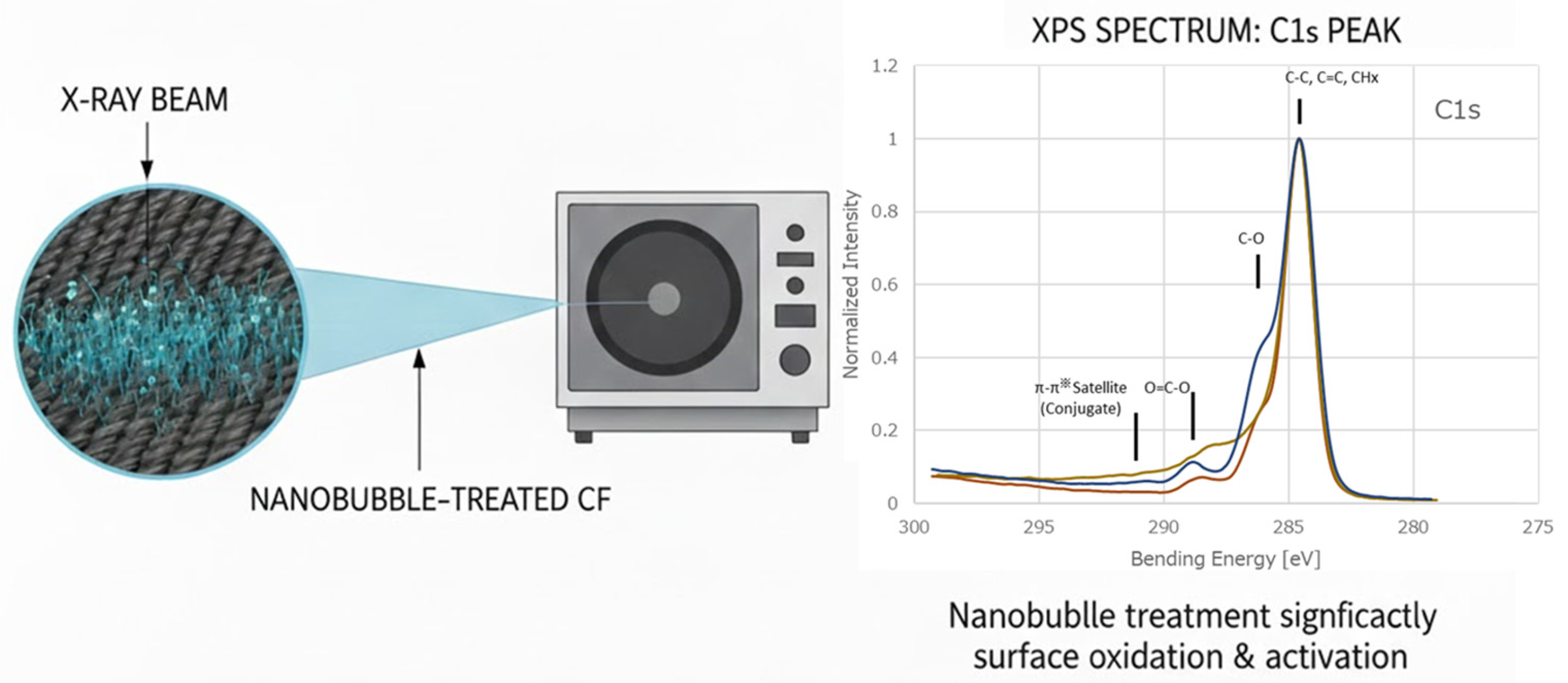
The surface chemical states and elemental composition of the carbon fibre samples with and without the nanobubble treatment were measured using X-ray photoelectron spectroscopy (XPS). When nanobubble treatment has effects on the CF surface, the number of chemical functional groups changes and can be detected with XPS intensity like in Figure 5.
The measurements were conducted on a K-Alpha (Thermo Fisher Scientific, Waltham, MA, USA) spectrometer employing a AlKαX-ray source operating at 1486.6 eV. The base pressure in the analysis chamber was maintained below 2 × 10⁻⁸ mbar during the measurement. The X-ray beam was 400 μm in diameter. Photoelectrons were collected at a take-off angle of 45 degrees. To correct surface charge accumulation during the measurement, a neutraliser gun was employed. All binding energies obtained from the measurement were calibrated by setting the adventitious C 1s peak at 284.6 eV. Wide-scan spectra were recorded over the range of 1300 eV to determine the overall elemental composition. Subsequently, high-resolution spectra of the C 1s, O 1s and N 1s core levels were acquired to allow for detailed functional group analysis. High-resolution spectra obtained from the measurement were subjected to curve-fitting analysis using the software. Peak components were fitted using a Shirley line shape after background subtraction.

2.4. Morphology of Nanobubble Treatment Carbon Fibre Surface

To check the damage and smoothness of carbon fibre surfaces after nanobubble treatment, scanning electron microscopy (SEM) was carried out with TM4000PLUS (Hitachi, Chiyoda, Japan). The SEM was operated at an accelerating voltage of 15 kV, and images were captured at a magnification of 5000×. All samples were not ion coated for SEM this time.

2.5. Single Fibre Pull-Out Test of Carbon Fibre Filament

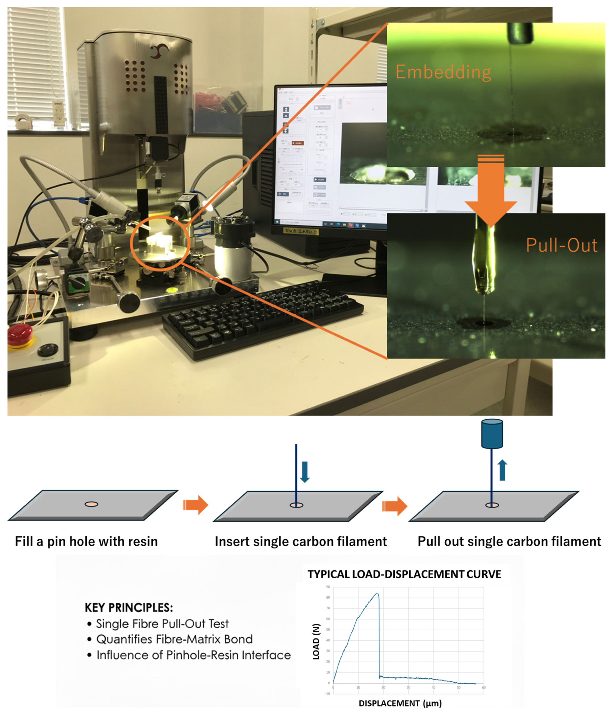
Single fibre pull-out test (Shinsousya Co. Ltd., Tokyo, Japan) was used to evaluate the interfacial shear strength between the resin and carbon fibre. This system has an advantage to evaluate the interfacial adhesion precisely because the recorded stress is not included and the extra force to grip the carbon fibre is unlikely in the micro droplet method [41,42]. In addition, the embedded length of reinforced fibre can be selected by the operator. The test equipment and procedure image are shown in Figure 6.
The tests were conducted at a temperature of 22–23 °C, identical to the water temperature in the nanobubble treatment, and a relative humidity of 25–40%. The pull-out rate was set at 0.03 mm/min, and the test was continued until the pull-out load reached zero. Data were obtained with n = 5 and the fibre embedded length is from 10 to 50 μm in this study. Displacement and lord data were recorded with 5 Hz for obtaining the curve. The diameter of carbon fibre was 7 μm, which was used for the interfacial shear strength (IFSS) calculation from the Toray company data sheet. The IFSS τ can be calculated using the following Equation (1), where Pmax is the maximum pull-out load, d is the fibre diameter, and L is the fibre embedded length:
τ = Pmax/πdL

3. Results and Discussion

3.1. Effect of Nanobubble Treatment on Carbon Fibre Surface

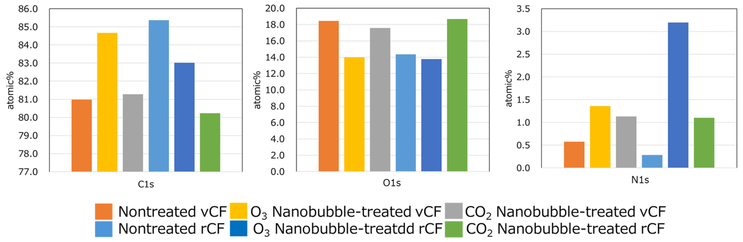
The XPS survey scans confirmed that both the nontreated and nanobubble-treated carbon fibres consisted primarily of carbon (C) and oxygen (O), with minor contributions from nitrogen (N) and trace elements, as shown in Figure 7.
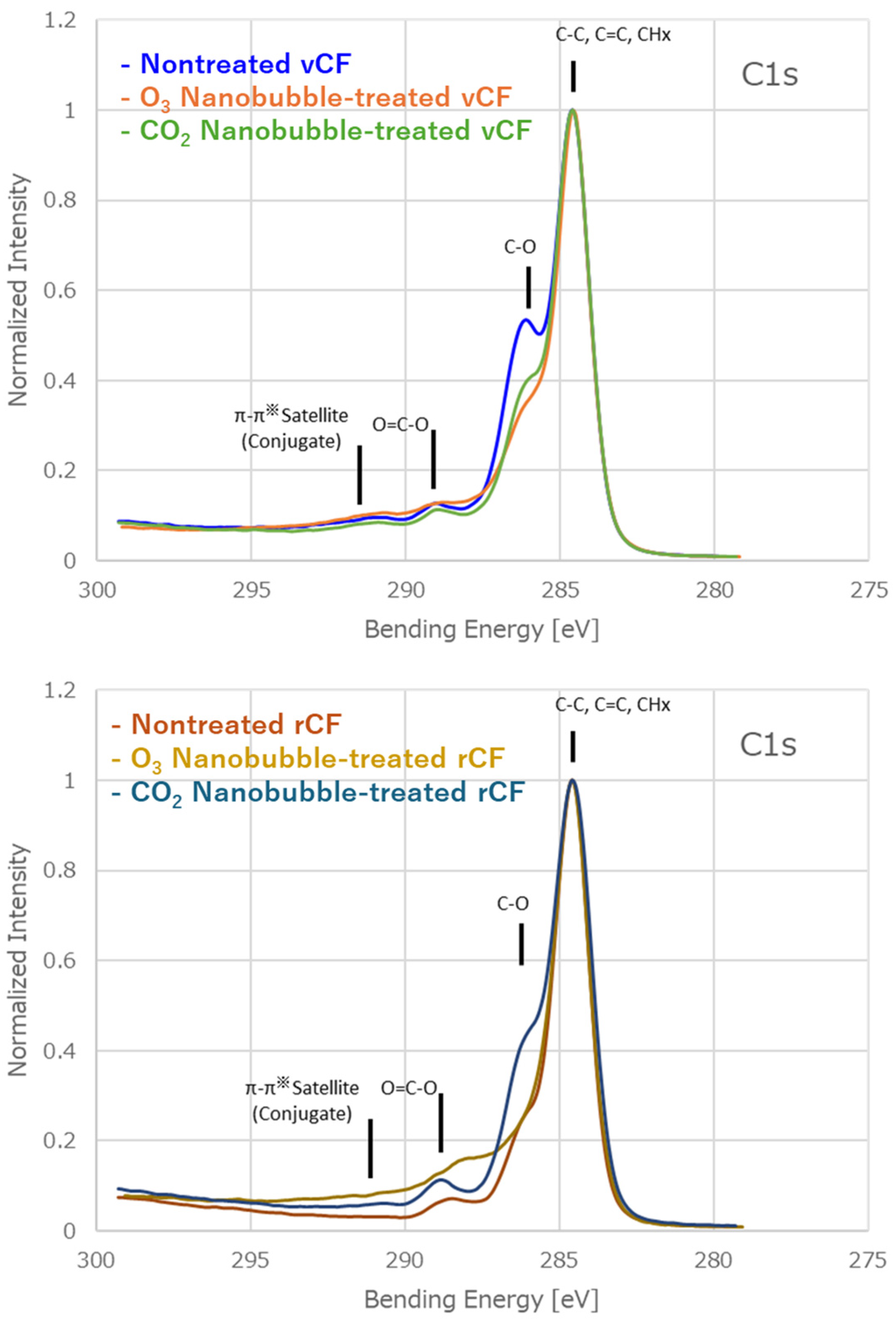
The surface oxygen content was supposed to be increased with the surface modification, as evidenced by O3 or CO2 nanobubble treatment, due to the oxidation process. The value, however, was not simply increased except for CO2 nanobubble-treated rCF. This suggests that the effect of nanobubble treatment was not simply the introduction of oxygen-containing functional groups onto the carbon fibre surface. The results were expected to be especially increased with O3 nanobubble treatments due to ozone’s powerful oxidation. On the other hand, the N 1s value, especially on rCF, was emphasised after the treatment. It is considered that the nitrogen atom could be captured on the excited carbon fibre surface during the air drying, efficiently entraining the nitrogen naturally contained in the ambient air due to nanobubbles. Several previous studies also mentioned similar results [43,44,45,46] in terms of nitrogen doping. In addition, this influence suggests that rCF is more intensified than vCF. As a result, the rCF surface is more sensitive compared to that of vCF. To elucidate the nature of these functional groups, high-resolution C 1s spectra were deconvoluted into multiple components based on their characteristic binding energies, as shown in Table 2 and Figure 8.
The distinct difference in the change following the surface treatment was observed between vCF and rCF. For vCF, the increase in C-C intensity suggests a surface-cleaning effect, where nanobubble treatment effectively removed surface contaminants or sizing residues, thereby exposing the graphitic core. In contrast, rCF exhibited a significant increase in oxygen-containing functional groups, particularly after both nanobubble treatments. This previous research indicated an increase in the interfacial adhesion strength [47]. Moreover, the notable rise in carboxyl (O-C=O) content (2.40% to 6.90%) in the O3 nanobubbles-mediated rCF indicates successful surface functionalisation, which is expected to enhance interfacial adhesion in composite applications. While the CO2 nanobubbles-mediated rCF did not influence the O-C=O group, it significantly changed the hydroxyl (C-O) content (21.55% to 31.32%). Thus, the different nanobubble’s gases O3 and CO2 have different effects on surface treatments.
Furthermore, the variations in the π–π satellite signals point towards a reorganisation of the sp2 hybridised framework. For vCF, the increased intensity signifies a clearer exposure of the conjugated backbone, whereas for rCF, the appearance of this peak confirms the re-establishment of surface crystallinity following the oxidative nanobubble treatment. As shown by the previous research of the authors of [25], nanobubble treatment surely has effects on the carbon-based crystalline. Beyond simple mechanical interlocking, the XPS data confirm that the nanobubble treatment provides a chemically active and electronically favourable surface. The refined electronic environment of the sp2 framework, evidenced by the π–π transitions, ensures a more intimate contact and robust charge-transfer interaction at the fibre–matrix interface.
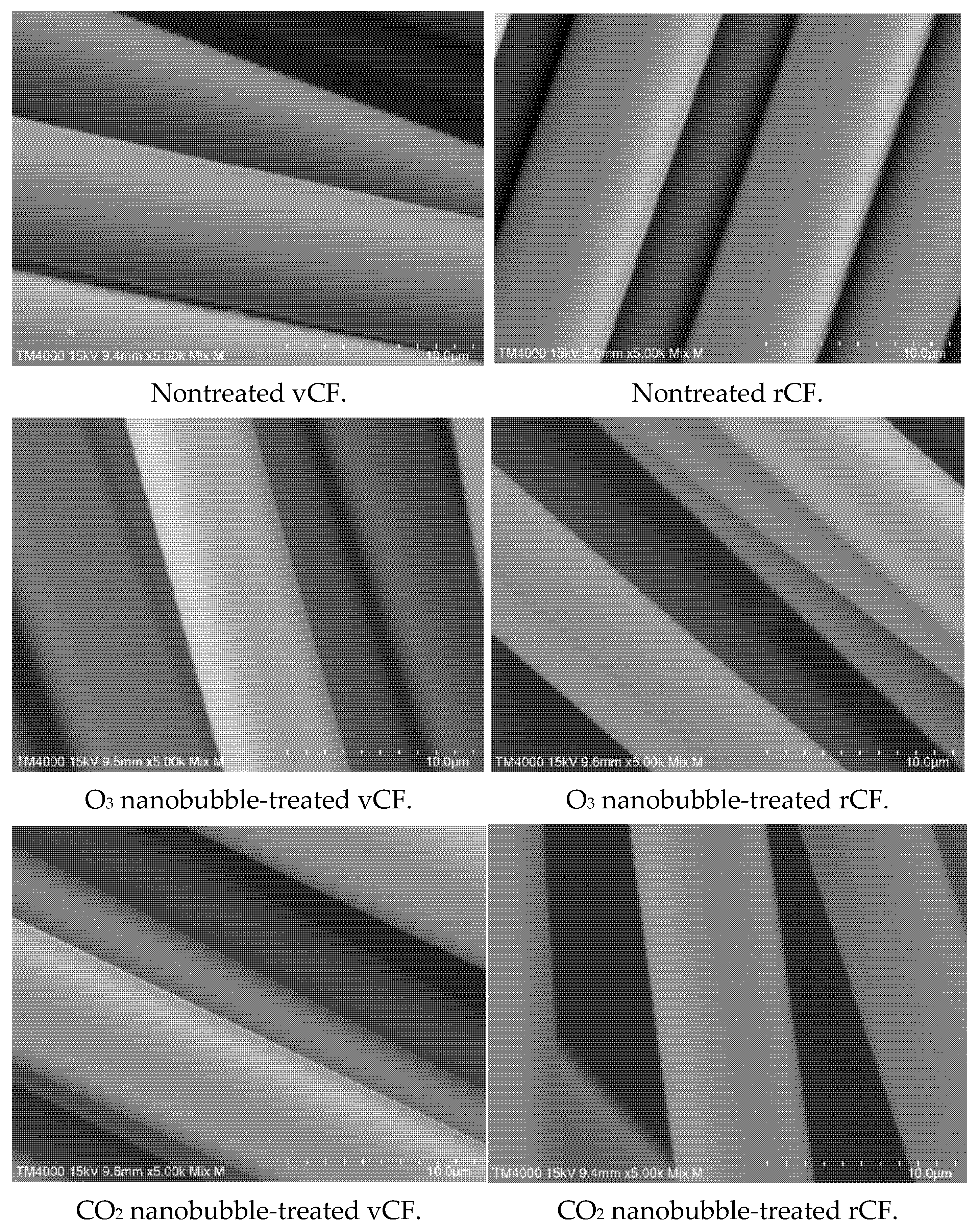
Not only chemical surface analysis, but also physical surface analysis was carried out with SEM observation. If nanobubble treatment could break the C-C bond itself, the roughness of the carbon fibre surface would be changed. SEM images of six different carbon fibre surfaces including non-nanobubble treatments and vCF/rCF are shown in Figure 9.
Comparing the SEM images before and after nanobubble treatment, there was no significant difference observed. This is evidence that nanobubble treatment did not affect any carbon fibre morphology and no physical property like anchor effect was added. On the other hand, from only these SEM images, it is not so easy to judge that nanosized anchors did not exist. From this point of view, further investigation such as atomic force microscopy (AFM) is needed. At this moment, the results suggest that the nanobubble treatment appears to have modified the more chemical properties of the carbon fibre surface.

3.2. Evaluation of the Interfacial Shear Strength (IFSS)

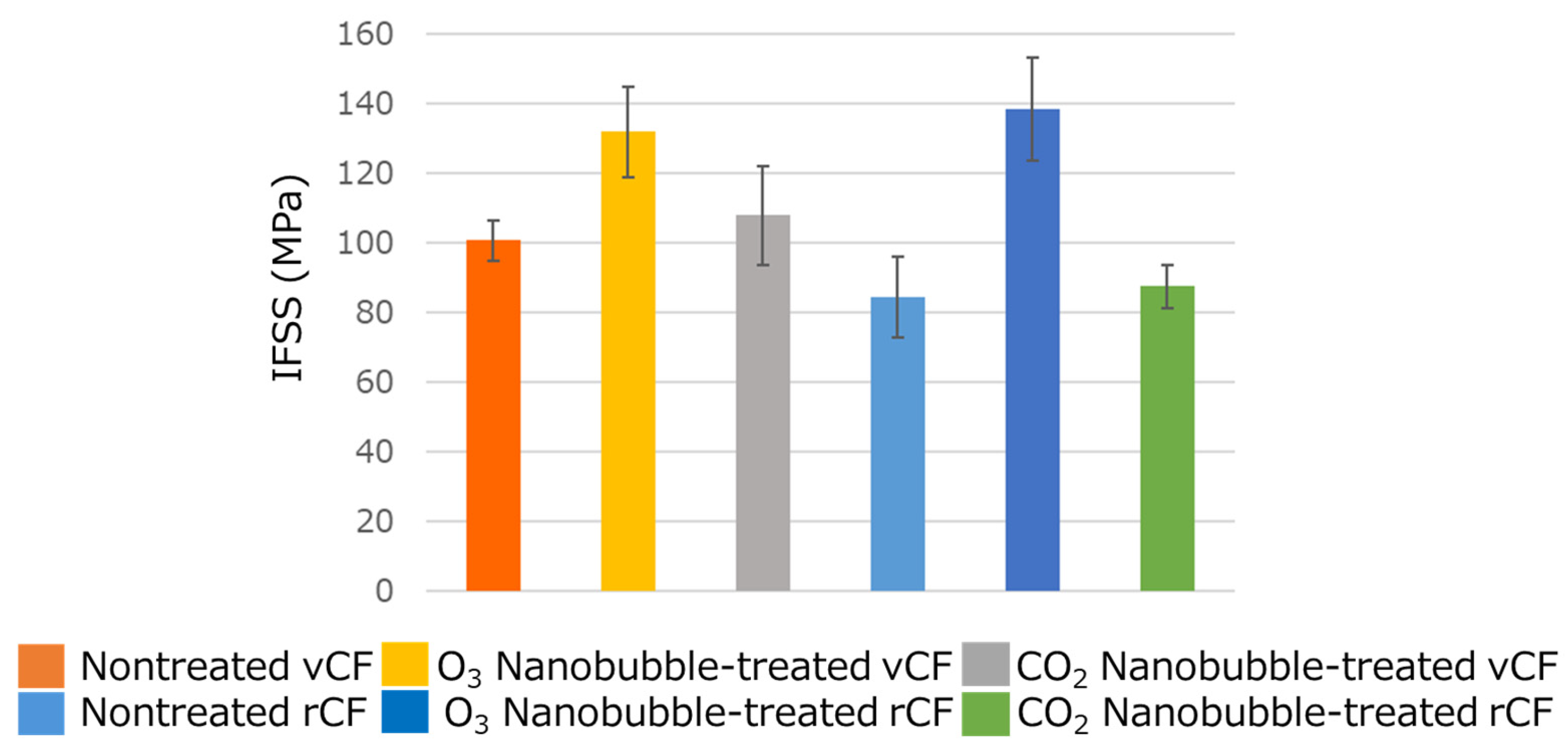
To evaluate the effect of nanobubble treatments with O3 or CO2, the pull-out test was carried out. The results of pin hole pull-out tests of various carbon fibre samples are shown in Figure 10.
Comparing the data between nontreated and nanobubble-treated vCF and rCF, nanobubble-treated carbon fibre exhibited higher IFSS than nontreated carbon fibres. For instance, the interfacial shear strength (IFSS) of O3 nanobubble-treated vCF was 132.0 ± 13.1 MPa, significantly higher than that of nontreated vCF showing 100.8 ± 5.8 MPa (p < 0.01). This suggests that nanobubble treatment changed to be more active to bond to the epoxy resin of the carbon fibre surface. In particular, O3 nanobubble treatment seems to have the most effective change to improve the interfacial adhesion. Surprisingly, the IFSS of rCF significantly increased from 84.5 ± 11.5 MPa to 138.5 ± 14.8 MPa, representing an improvement of approximately 60% due to the O3 nanobubbles treatment. This highlighted that the IFSS due to O3 nanobubbles treatment was more enhanced in rCFs than vCFs. According to our results in XPS analysis (Table 2), O3 nanobubble treatment enhanced O-C=O (carboxyl, ester) generation on the surface. It is indicated that the reaction between these functional groups and the epoxy resin further reinforced the interfacial adhesion strength with the carbon fibre. Conversely, a marginal improvement in interfacial adhesion was also observed in the CO2 nanobubble treatment, where hydroxyl groups were increased. Collectively, these results indicate that nanobubble treatment successfully introduces new functional groups onto the carbon fibre surface, thereby enhancing the interfacial bonding with the resin.
However, the optimal gas species for generating nanobubbles may vary depending on the specific choice of resin. This remains a subject for further investigation; nevertheless, it highlights a distinct advantage of the present methodology, underscoring the versatility of this approach which enables the strategic selection of gas species based on the desired chemical functionality.

4. Conclusions

In this study, a novel sustainable surface treatment method for carbon fibres utilising nanobubbles was developed. This approach demonstrates advantages for recycled carbon fibres (rCFs), as it can be readily integrated into existing processes such as the cleaning stage, thereby facilitating industrial implementation. The efficacy of nanobubble treatments using O3 and CO2 was experimentally and analytically evaluated on both virgin carbon fibres (vCFs) and rCFs to assess their differential effects.
The results revealed that the nanobubble treatment yielded substantial generation of functional groups on the carbon fibre surface, thereby highlighting the feasibility of nanobubble-based surface modification. Nanobubble treatments can remove the chemical compounds from the carbon surface. This phenomenon was observed in vCF samples, and this was the primary factor that O content was decreased after the treatment. On the other hand, nanobubble treatments can introduce some extra functional groups to bare carbon surfaces like rCF. In addition, nanobubble treatments make the excited carbon surface as a result of N content as shown in XPS analysis. This suggests that carbon fibres after the nanobubble treatment were exposed to the selected atmosphere, then selected elements could be captured on the carbon fibres.
To validate the surface treatment efficacy, single fibre pull-out tests were conducted to measure the interfacial shear strength between all fibre samples and epoxy resin. Notably, the findings demonstrated a significant enhancement in interfacial shear strength for nanobubble treatment samples, consistent with the XPS analysis. In particular, the interfacial shear strength of rCF was increased by over 60% due to O3 nanobubble treatment, rising from 84.5 ± 11.5 MPa to 138.5 ± 14.8 MPa. This significant strengthening of carbon fibre was also found in vCF. Although the study of CO2 nanobubble treatment showed only a slight increase in the interfacial shear strength in this study, we attribute this to the specific chemical compatibility between the generated functional groups and the resin matrix. We suggest that the hydroxyl group generated by the CO2 nanobubble treatment could exhibit greater bonding potential with non-epoxy resin systems.
These findings suggest that nanobubble treatment presents a promising alternative to conventional surface treatment methods, offering a more environmentally benign and sustainable approach for carbon fibre processing. Further investigations into the optimisation and the scalability and long-term performance of this treatment methodology are warranted to establish its viability for practical applications.

Author Contributions

G.M.: Original draft writing, Data curation, Conceptualization, Methodology, Visualisation, Investigation, Writing—review and editing; S.A.: Data curation and Methodology; A.K.: Data curation and Methodology; J.K.: Data curation, Supervision, Writing—review and editing; T.Y.: Supervision, Writing—revision and editing, Resources. All authors have read and agreed to the published version of the manuscript.

Funding

This research was founded by JSPS KAKENHI grant number JP25H00768.

Data Availability Statement

The original contributions presented in this study are included in the article. Further inquiries can be directed to the corresponding author.

Acknowledgments

Our heartfelt thanks go to Tatsuta Boseki Co. Ltd. for their kind donation of materials, which made this study possible. We are truly grateful for their generosity and the trust they placed in our research endeavours. The authors would like to acknowledge the Innovative Composite Centre (ICC) for the XPS analysis. Special thanks are due to Oda for her technical support and helpful discussions.

Conflicts of Interest

The authors declare the following financial interests/personal relationships which may be considered as potential competing interests: GO MASUDA reports were provided by the University of Tokyo.

References

  1. Zhang, J.; Lin, G.; Vaidya, U.; Wang, H. Past, present and future prospective of global carbon fibre composite developments and applications. Compos. Part B 2023, 250, 110463. [Google Scholar] [CrossRef] [Scilit]
  2. Panagiotis, C.J. Recycling of Carbon Fiber-Reinforced Composites-A Review. Int. J. Adv. Res. Sci. Commun. Technol. 2024, 4, 433–455. [Google Scholar] [CrossRef] [Scilit]
  3. Zabihi, O.; Zamani, P.; Yadav, R.; Wei, Y.; Laghaei, M.; Pakdel, E.; Ahmadi, M.; Li, Q.; Hadigheh, S.A.; Naebe, M. The sustainability spectrum of carbon fibre: Balancing high performance CFRP composites with environmental responsibility. Adv. Compos. Hybrid Mater. 2025, 8, 1–52. [Google Scholar] [CrossRef] [Scilit]
  4. Borges, C.; Chícharo, A.; Araújo, A.; Silva, J.; Santos, R.M. Designing of carbon fiber-reinforced polymer (CFRP) composites for a second-life in the aeronautic industry: Strategies towards a more sustainable future. Sec. Polym. Compos. Mater. 2023, 10, 3389. [Google Scholar] [CrossRef] [Scilit]
  5. Pimenta, S.; Pinho, S.T. Recycling carbon fibre reinforced polymers for structural applications: Technology review and market outlook. Waste Manag. 2011, 31, 378–392. [Google Scholar] [CrossRef] [Scilit]
  6. Ateeq, M. A state of art review on recycling and remanufacturing of the carbon fiber from carbon fiber polymer composite. Compos. Part C Open Access 2023, 12, 100412. [Google Scholar] [CrossRef] [Scilit]
  7. Qureshi, J. A Review of Recycling Methods for Fibre Reinforced Polymer Composites. Sustainability 2022, 14, 16855. [Google Scholar] [CrossRef] [Scilit]
  8. Lefeuvre, A.; Garnier, S.; Jacquemin, L.; Pillain, B.; Sonnemann, G. Anticipating in-use stocks of carbon fiber reinforced polymers and relevant carbon fiber streams by composite recycling. Resour. Conserv. Recycl. 2017, 125, 264–272. [Google Scholar] [CrossRef] [Scilit]
  9. Pimenta, S.; Pinho, S.T. The effect of recycling on the mechanical response of carbon fibres and their composites. Compos. Struct. 2012, 94, 3669–3684. [Google Scholar] [CrossRef] [Scilit]
  10. Cousins, D.S.; Suzuki, Y.; Murray, R.E.; Samaniuk, J.R.; Stebner, A.P. Recycling glass fiber thermoplastic composites from wind turbine blades. J. Clean. Prod. 2019, 209, 1252–1263. [Google Scholar] [CrossRef] [Scilit]
  11. Oliveux, G.; Dandy, L.O.; Leeke, G.A. Current status of recycling of fibre reinforced polymers: Review of technologies, reuse and resulting properties. Prog. Mater. Sci. 2015, 72, 61–99. [Google Scholar] [CrossRef] [Scilit]
  12. Krauklis, A.E.; Karl, C.W.; Gagani, A.I.; Jørgensen, J.K. Composite Material Recycling Technology—State-of-the-Art and Sustainable Development for the 2020s. J. Compos. Sci. 2021, 5, 28. [Google Scholar] [CrossRef] [Scilit]
  13. Pickering, S.J. Recycling technologies for thermoset composite materials—Current status. Compos. Part A Appl. Sci. Manuf. 2006, 37, 1206–1215. [Google Scholar] [CrossRef] [Scilit]
  14. Butenegro, J.A.; Bahrami, M.; Martínez, M.Á.; Abenojar, J. Reuse of Carbon Fibers and a Mechanically Recycled CFRP as Rod-like Fillers for New Composites: Optimization and Process Development. Processes 2023, 11, 366. [Google Scholar] [CrossRef] [Scilit]
  15. Jiang, G.; Pickering, S.J.; Walker, G.S.; Wong, K.H.; Rudd, C.D. Surface characterisation of carbon fibre recycled using fluids at supercritical and subcritical conditions. Appl. Surf. Sci. 2008, 254, 2588–2593. [Google Scholar] [CrossRef] [Scilit]
  16. Pakdel, E.; Kashi, S.; Varley, R.; Wang, X. Recent progress in recycling carbon fibre reinforced composites and dry carbon fibre wastes. Resour. Conserv. Recycl. 2021, 166, 105340. [Google Scholar] [CrossRef] [Scilit]
  17. Zhang, J.; Chevali, V.S.; Wang, H.; Wang, C.-H. Current status of carbon fibre and carbon fibre composites recycling. Compos. Part B 2020, 193, 108053. [Google Scholar] [CrossRef] [Scilit]
  18. Peng, X.; Wu, Y.; Wei, Z. Research progress on the surface modification of carbon fiber. RSC Adv. 2024, 14, 4043–4064. [Google Scholar] [CrossRef]
  19. Gao, B.; Zhang, R.; Gao, F.; He, M.; Wang, C.; Liu, L.; Zhao, L.; Cui, H. Interfacial Microstructure and Enhanced Mechanical Properties of Carbon Fiber Composites Caused by Growing Generation 1–4 Dendritic Poly(amidoamine) on a Fiber Surface. Langmuir 2016, 32, 8339–8349. [Google Scholar] [CrossRef] [Scilit]
  20. Lee, J.H.; Lee, S.H.; Suh, D.H. Using nanobubblized carbon dioxide for effective microextraction of heavy metals. J. CO2 Util. 2020, 39, 101163. [Google Scholar] [CrossRef] [Scilit]
  21. Nan, Z.; Xu, L.; Ren, Y.; Lu, J.; Sun, Y.; Zhang, D.; He, J. Recovery of Carbon Fibers from Carbon Fiber-Reinforced Plastics Using Microwave-Assisted Sulfuric Acid Treatment and Reuse of Recycled Carbon Fibers. Processes 2025, 13, 1437. [Google Scholar] [CrossRef] [Scilit]
  22. Santos, A.L.; Botelho, E.C.; Kostov, K.G.; Ueda, M.; da Silva, L.L.G. Carbon Fiber Surface Modification by Plasma Treatment for Interface Adhesion Improvements of Aerospace Composites. Adv. Mater. Res. 2016, 1135, 75–87. [Google Scholar] [CrossRef] [Scilit]
  23. Tiwari, S.; Bijwe, J.; Panier, S. Polyetherimide composites with gamma irradiated carbon fabric: Studies on abrasive wear. Wear 2011, 270, 688–694. [Google Scholar] [CrossRef] [Scilit]
  24. Lin, J.S. Surface characteristics and microscopic interfacial adhesion of carbon fibers modified by various techniques. J. Appl. Polym. Sci. 2002, 84, 2056–2067. [Google Scholar]
  25. Masuda, G.; Enyoh, C.E.; Wang, W.; Anzai, S.; Wang, Q. Ozone Nanobubble-Assisted Pretreatment of Lignocellulose: Enhancing Wood Liquefaction and Bio-Polyurea Development. Appl. Sci. 2025, 15, 4618. [Google Scholar] [CrossRef] [Scilit]
  26. Foudas, A.W.; Kosheleva, R.I.; Favvas, E.P.; Kostoglou, M.; Mitropoulos, A.C.; Kyzas, G.Z. Fundamentals and applications of nanobubbles: A review. Chem. Eng. Res. Des. 2023, 189, 64–86. [Google Scholar] [CrossRef] [Scilit]
  27. Jia, J.; Zhu, Z.; Chen, H.; Pan, H.; Jiang, L.; Su, W.-H.; Chen, Q.; Tang, Y.; Pan, J.; Yu, K. Full life circle of micro-nano bubbles: Generation, characterization and applications. Chem. Eng. J. 2023, 471, 144621. [Google Scholar] [CrossRef] [Scilit]
  28. Arata Kioka, M.N. Theoretical and experimental perspectives in utilizing nanobubbles as inhibitors of corrosion and scale in geothermal power plant. Renew. Sustain. Energy Rev. 2021, 149, 111373. [Google Scholar] [CrossRef] [Scilit]
  29. Atkinson, A.J.; Apul, O.G.; Schneider, O.; Garcia-Segura, S.; Westerhoff, P. Nanobubble Technologies Offer Opportunities To Improve Water Treatment. Acc. Chem. Res. 2019, 52, 1196−1205. [Google Scholar] [CrossRef] [Scilit]
  30. Alheshibri, M.; Qian, J.; Jehannin, M.; Craig, V.S.J. A history of Nanobubbles. Langmuir 2016, 32, 11086–11100. [Google Scholar] [CrossRef] [Scilit]
  31. Pal, P.; Kioka, A.; Arakawa, E.; Anzai, S.; Tsuji, T. Nanobubble technology: An environmentally sustainable approach for gas dissolution and water chemistry modulation. Chem. Eng. J. Green Sustain. 2026, 1, 100021. [Google Scholar] [CrossRef] [Scilit]
  32. Huang, Q.; Butaye, P.; Ng, P.H.; Zhang, J.; Cai, W.; St-Hilaire, S. Impact of low-dose ozone nanobubble treatments on antimicrobial resistance genes in pond water. Front. Microbiol. 2024, 15, 1393266. [Google Scholar] [CrossRef] [Scilit] [PubMed]
  33. Khuntia, S.; Majumder, S.K.; Ghosh, P. Removal of Ammonia from Water by Ozone Microbubbles. Ind. Eng. Chem. Res. 2013, 52, 318–326. [Google Scholar] [CrossRef] [Scilit]
  34. Lyu, T.; Wu, Y.; Zhang, Y.; Fan, W.; Wu, S.; Mortimer, R.J.G.; Pan, G. Nanobubble aeration enhanced wastewater treatment and bioenergy generation in constructed wetlands coupled with microbial fuel cells. Sci Total Env. 2023, 895, 165131. [Google Scholar] [CrossRef] [Scilit]
  35. Maie, N.; Anzai, S.; Tokai, K.; Kakino, W.; Taruya, H.; Ninomiya, H. Using oxygen/ozone nanobubbles for in situ oxidation of dissolved hydrogen sulfide at a residential tunnel-construction site. J. Env. Manag. 2022, 302, 114068. [Google Scholar] [CrossRef] [Scilit]
  36. Singh, B.; Park, G.; Ryu, J.-H.; Park, M.-H. Micro-Nanobubble Technology in Surface Cleaning and Defouling. Appl. Sci. 2025, 15, 1197. [Google Scholar] [CrossRef] [Scilit]
  37. He, J.; Zhou, Y.; Geilfus, C.M.; Cao, J.; Fu, D.; Baram, S.; Liu, Y.; Li, Y. Enhancing tomato fruit antioxidant potential through hydrogen nanobubble irrigation. Hortic. Res 2024, 11, uhae111. [Google Scholar] [CrossRef] [Scilit]
  38. Lee, J.H.; Lee, S.H.; Suh, D.H. High micropore number and specific surface of carbon fibers pretreated with a swarm of CO2 micro–nanobubbles. Environ. Chem. Lett. 2021, 19, 3565–3571. [Google Scholar] [CrossRef] [Scilit]
  39. Ma, F.; Tao, D. A Study of Mechanisms of Nanobubble-Enhanced Flotation of Graphite. Nanomaterials 2022, 12, 3361. [Google Scholar] [CrossRef] [Scilit]
  40. Ansari, M.S.; Zafar, S.; Pathak, H. A comprehensive review of surface modification techniques for carbon fibers for enhanced performance of resulting composites. Results Surf. Interfaces 2023, 12, 100141. [Google Scholar] [CrossRef] [Scilit]
  41. Zhandarov, S.; Mäder, E. Characterization of fiber/matrix interface strength: Applicability of different tests, approaches and parameters. Compos. Sci. Technol. 2005, 65, 1496–1511. [Google Scholar] [CrossRef] [Scilit]
  42. Beckert, W.; Lauke, B. Critical discussion of the single-fibre pull-out test: Does it measure adhesion? Compos. Sci. Technol. 1998, 57, 1689–1706. [Google Scholar] [CrossRef] [Scilit]
  43. Lin, J.; Sun, C.; Min, J.; Wan, H.; Wang, S. Effect of atmospheric pressure plasma treatment on surface physicochemical properties of carbon fiber reinforced polymer and its interfacial bonding strength with adhesive. Compos. Part B Eng. 2020, 199, 108237. [Google Scholar] [CrossRef] [Scilit]
  44. Kong, L.; Wang, X.; Zheng, W.; Tian, S.; Qi, Y.; Xue, Y.; Wang, B. Effects of plasma treatment onproperties of carbonfiber and its reinforced resin composites. Mater. Express Res. 2020, 7, 065304. [Google Scholar] [CrossRef] [Scilit]
  45. Thurakitseree, T.; Kramberger, C.; Chanlek, N.; Nakajima, H. Possibility of doping nitrogen into single-walled carbon nanotubes by γ-irradiated N2 molecules. Radiat. Phys. Chem. 2021, 186, 109524. [Google Scholar] [CrossRef] [Scilit]
  46. Thurakitseree, T.; Kramberger, C.; Chanlek, N.; Supruangnet, R.; Wisitsorraat, A.; Nakajima, H.; Maruyama, S. The Inuence of γ-Irradiation on Nitrogen Configuration in Nitrogen-Doped Single-Walled Carbon Nanotubes. Diam. Relat. Mater. 2020, 101, 107569. [Google Scholar] [CrossRef] [Scilit]
  47. Morita, M.; Oya, Y.; Kato, N.; Mori, K.; Koyanagi, J. Effect of Electrostatic Interactions on the Interfacial Energy between Thermoplastic Polymers and Graphene Oxide: A Molecular Dynamics Study. Polymers 2022, 14, 2579. [Google Scholar] [CrossRef] [Scilit]
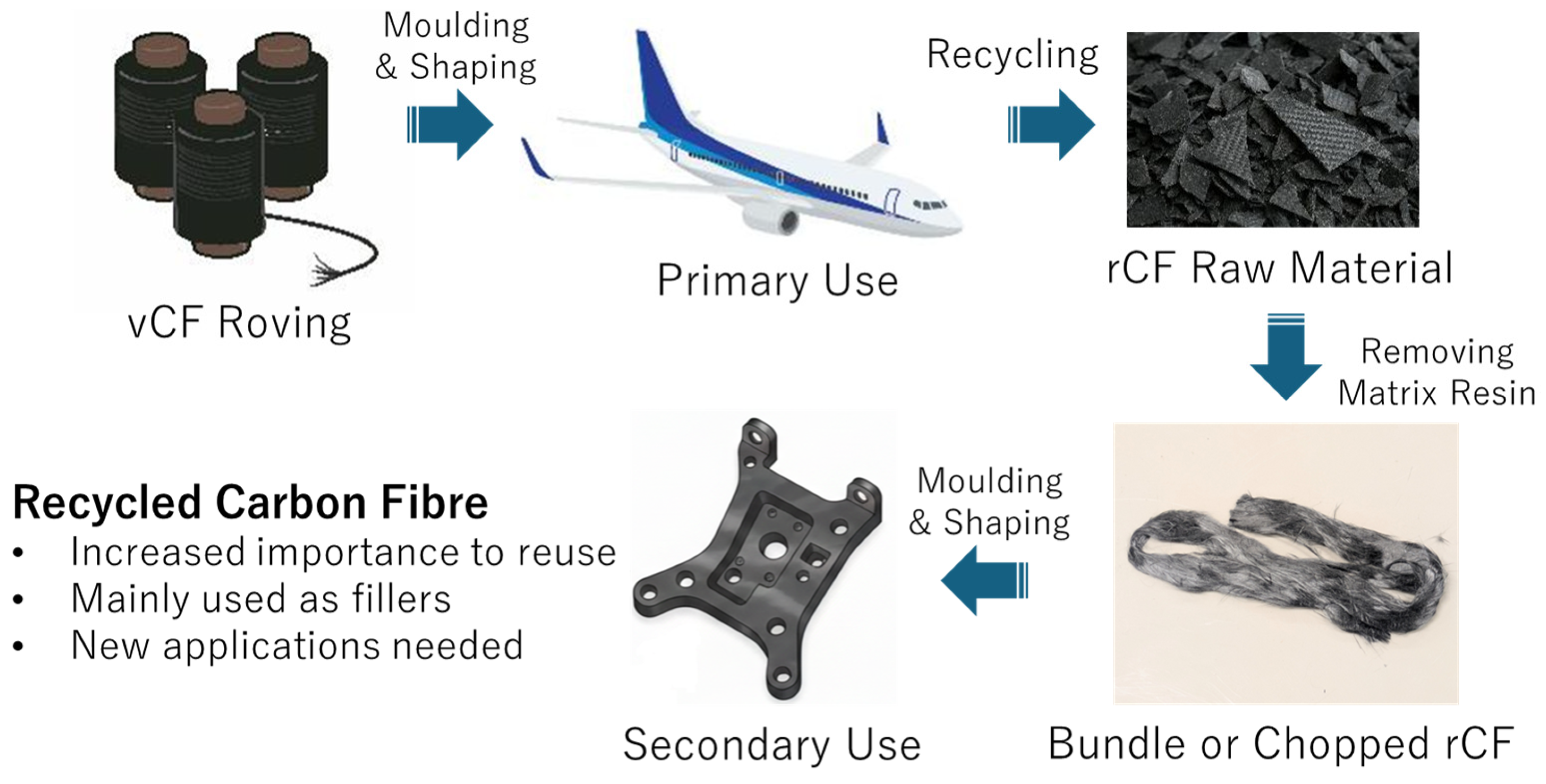
Figure 1. Carbon fibre use cycle from primary to secondary use.
Processes 14 00749 g001
Figure 2. Key characteristics in nanobubbles compared to larger bubbles.
Processes 14 00749 g002
Figure 3. rCF bundle used in this research.
Processes 14 00749 g003
Figure 4. Nanobubble treatment on carbon fibre proposed in this study.
Processes 14 00749 g004
Figure 5. Hypothesised effects on nanobubble-mediated carbon fibre samples detected in XPS spectrum.
Processes 14 00749 g005
Figure 6. Principles of single fibre pull-out test and the typical graph data.
Processes 14 00749 g006
Figure 7. Results of C 1s, O 1s, and N 1s identified in XPS analysis.
Processes 14 00749 g007
Figure 8. XPS C 1s spectra of vCF (top) and rCF (bottom) samples.
Processes 14 00749 g008
Figure 9. SEM images of each condition of carbon fibre samples.
Processes 14 00749 g009
Figure 10. IFSS of various carbon fibre samples in this study.
Processes 14 00749 g010
Table 1. The comparison of carbon fibre surface modification methodologies.
MethodologyAdvantagesDisadvantages
Sulfuric acidMost established industrial method; ensures uniform etching and significantly boosts adhesion.Requires handling of hazardous electrolytes; substantial burden regarding acidic waste disposal.
MicrowaveRapid, localised heating; relatively high energy efficiency during the reaction phase.Risk of non-uniformity; high capital expenditure for continuous large-scale production lines.
PlasmaA dry process; eliminates the need for aqueous waste. Highly effective at increasing surface free energy.Requires high-vacuum chambers, leading to high costs; limited penetration into dense fibre tows.
γ-ray irradiationExceptional penetration; modifies the interior of fibre bundles uniformly at ambient temperatures.Necessity for specialised radiological facilities; stringent safety regulations and perceived environmental risks.
NanobubbleUtilises only water and air/gas. Zero hazardous waste. Low energy consumption; preserves mechanical integrity.Currently scaling up from pilot to full industrial mass production.
Table 2. The comparison of nontreated and nanobubble-treated vCF and rCF.
Functional Group AssignmentNontreated vCF Area (%)O3 Nanobubble-Treated vCF Area (%)CO2 Nanobubble-Treated vCF Area (%)Nontreated rCF Area (%)O3 Nanobubble-Treated rCF Area (%)CO2 Nanobubble-Treated rCF Area (%)
C-C, C-H (Graphitic/Hydrocarbon)58.0368.0766.2876.0471.6765.85
C-O
(Hydroxyl, Ether)
38.0625.5929.9221.5517.9131.32
O-C=O
(Carboxyl, Ester)
2.704.072.732.406.902.60
π–π Satellite
(Conjugate)
1.222.271.07-3.520.24
Disclaimer/Publisher’s Note: The statements, opinions and data contained in all publications are solely those of the individual author(s) and contributor(s) and not of MDPI and/or the editor(s). MDPI and/or the editor(s) disclaim responsibility for any injury to people or property resulting from any ideas, methods, instructions or products referred to in the content.