Article

Synergistic Optimization Tribological and Mechanical Properties of Carbon Fiber-Reinforced Recyclable Indole-Based Poly(hexahydrotriazine) Composites via FeOOH Nanoparticles and Fe3+–π Interaction
1
School of Automotive Engineering, Shaanxi College of Communications Technology, Xi’an 710018, China
2
School of Materials Science & Engineering, Shaanxi University of Science & Technology, Xi’an 710021, China
*
Author to whom correspondence should be addressed.
Processes 2026, 14(17), 2708; https://doi.org/10.3390/pr14172708
Submission received: 9 July 2026 / Revised: 17 August 2026 / Accepted: 21 August 2026 / Published: 25 August 2026
(This article belongs to the Section Materials Processes)

Abstract

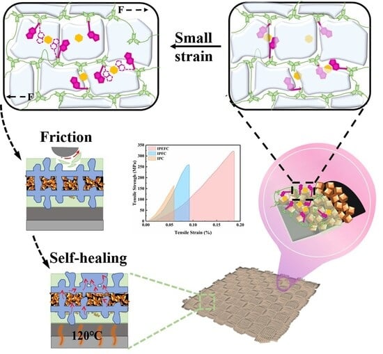
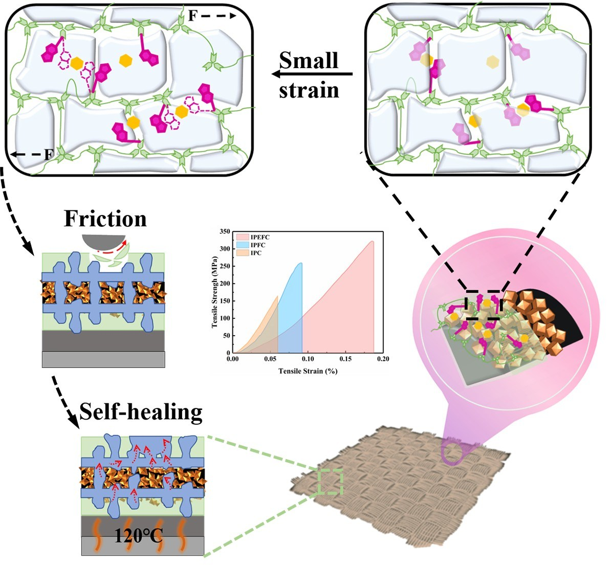
The sturdy and stable unique polyhedral structure of FeOOH nanoparticles facilitates stress and load transfer, thereby forming a tighter mechanical interlock at the carbon fiber–matrix interface. In this work, the FeOOH nanocrystal layer in situ grown on flexible carbon fiber cloth was rationally designed and fabricated through hydrothermal synthesis. Then, the non-covalent cation–π bond was constructed at the interface between the iron ion-loaded FeOOH nanoparticles and indole-based poly(hexahydrotriazine) (In-PHT). Owing to the collaborative effects of physical anchoring and chemical bonding, the resultant composite exhibited an outstanding tensile strength of 322 MPa, and the friction coefficient significantly decreased by 63% compared with the composites without FeOOH nanoparticles. Moreover, the resultant worn composite showed an excellent self-healing property owing to the introduction of polyethylene wax (PEW) with a low melting point, and the healed friction coefficient remained almost unchanged. Extensive analyses verify that the phase-separated structure and Fe3+–π interactions across multiscale interfaces achieve the combined advantages of wear resistance and durability for recyclable carbon fiber-reinforced poly(hexahydrotriazine) composites (PHT-CFRPs).

Graphical Abstract

1. Introduction

The recyclable PHT-CFRPs have attracted increasing attention in both academia and industry, owing to their virtues of light weight, corrosion resistance, and the nondestructive recyclability of carbon fibers [1,2]. The bulk mechanical properties of PHT-CFRPs mainly depend upon the effective interaction between CF and PHT matrix, as well as the stable interface load-bearing capacity [3,4]. Therefore, much research effort has been dedicated to the interface structure variation of PHT-CFRPs to improve the comprehensive properties of PHT-CFRPs. Modification strategies that focus on the CF surface, such as polymer-agent sizing [5,6,7] and nanoparticle assembling [8,9,10], have been adopted to effectively enhance interlayer adhesion of PHT-CFRPs via increasing the mechanical interlocking [11,12,13] and wettability [14,15,16]. The sizing agents protect the CF surface and endow PHT-CFRPs with preferable mechanical properties, but, in the flexible-sizing transition layer, there exists a defect of feeble bearing capacity. The introduction of a hard nanophase can alleviate this issue. In our previous study [1], carbon nanotubes (CNTs) were grown on CFs via vapor deposition, which significantly improved the interfacial properties of the composite. However, due to cohesive failure, some CNTs were pulled out, and the tensile strength did not significantly improve. There are also defects in the effective adhesion of two-dimensional materials on the CF surface. Ayyagari et al. [17] obtained ordered MOF porous structures by using highly concentrated metal source solutions, but there are still very few plow-like grooves on the CF surface. Therefore, the structural stability of nanomaterials has become the primary problem affecting the effective interface bonding construction.
In the past 2 years, FeOOH nanoparticles with a stable polyhedral structure have received some attention from scholars, and some relative research has been carried out. Lin et al. [18] selected hydrothermal synthesis to modify uniformly FeOOH on the surface of CF, which could sustain the impact of harsh conditions, such as laundering under acidic and basic conditions. These stable nano interfaces not only provide effective physical entanglement but also bear and disperse large loads. Nevertheless, effective mechanical anchoring of the interface still needs the assistance of the chemical bond [19]. Therefore, the next key research point becomes coordinating the compatibility between stable nanostructures and the covalent cross-linking network for the PHT matrix. Recently, the construction of a cation–π cross-linked polymer has received considerable theoretical and experimental attention. The strength of a non-covalent cation–π can even be compared to certain covalent interactions, which can be constructed through indole groups and metal ions [20]. The hexahydro–triazine ring of PHT endows it with depolymerization properties [21], which can also be applied to synthetize the In-PHT matrix with the indole group [22]. The contribution of the π-face from the indole ring provides the initial condition for the establishment of a non-covalent cation-π [23,24]. Another necessary factor is requiring a stable adsorption of free metal cations on CF. The adsorption of metal ions via nano-phase grown on a CF surface is a feasible solution to establish an effectively cation–π attraction between the nanophase and polymer matrix [25,26,27]. The tetrahedral-structured FeOOH nanoparticles with few Fe3+ were fabricated by Lin Z et al. [28], making them favorable for superior interfacial chemical bonding. Using FeOOH with iron ions to modify CF could fully utilize its cross-scale synergistic enhancement effect and effectively boost the interface property of PHT-CFRPs. Based on the effective transfer of interfacial stress, the introduction of the PEW lubricant with a low melting point can further alleviate interfacial stress concentration via the plastic deformation mechanism [29,30]. This is beneficial not only for deflecting the interlayer crack associated [31,32], but also for the construction of lubricating film and improving tribological performance.
In this work, FeOOH nanoparticle-modified carbon fiber reinforcements were employed to enhance interfacial stress and load transfer in PHT-CFRPs, with the Fe3+ ions loaded on the nanoparticles serving to establish cation–π interactions with indole groups between the carbon fiber and the In-PHT matrix. To further alleviate stress concentration at the interlayer and to introduce a lubricating phase for improved wear resistance, PEW was incorporated into the composite system. The resulting PHT-CFRPs are expected to exhibit enhanced tribological performance and mechanical ductility, as well as self-healing capability upon thermal treatment. Notably, the non-destructive recovery of carbon fibers from the composites is anticipated to remain unaffected by the modifications. This work provides a viable strategy for strengthening interlayer adhesion in PHT-CFRPs and offers insight into the underlying mechanisms governing the interfacial interactions.

2. Materials and Methods

2.1. Materials

The N-methyl-2-pyrrolidone (NMP), 4-aminoindole (4-In), 4,4′-(1,3-phenylenedioxy) dianiline (POD), Ferric chloride hexahydrate (FeCl3·6H2O), ammonium fluoride (NH4F) pyrophosphatic acid (PPi), and concentrated sulfuric acid (H2SO4) were offered by the China Shanghai Sinopharm Chemical Reagent Co., Ltd. (Shanghai, China). The PEW was contributed by Micropowder Company (Tarrytown, NY, USA), and the diameter of PEW was about 3–4 μm. The paraformaldehyde (PFA) was delivered by Aladdin Bio-Chem Technology Co., Ltd. (Shanghai, China). All materials were analytical reagent and used as received unless otherwise noted.

2.2. Growth of FeOOH Nanoparticles on the CF and Attachment of Fe3+ on the FeOOH Nanoparticles

The industrial size on the purchased CF needs to be cleaned by soaking in solution, which was prepared by mixing acetone and ethanol with 1:2 mass ratio, which should be soaked in the solution for 24 h. After being washed with ionic water, it should be placed in an oven at 60 °C for 12 h. The modification of pretreated CF was performed using a simple hydrothermal method to cover with the FeOOH nanoparticle layer, and it follows two steps: Firstly, the FeCl3 was solvated in 50 mL of pure water with mixing for 30 min, followed by the additional of NH4F and stirring for 3 h. In order to find the best mechanical properties, we tried the reaction ratio as shown in Table S1. Secondly, the prepared solution was transferred to the reactor, and the 50 × 50 mm CF was fully soaked and reacted at 100 °C for 16 h. Upon cooling to room temperature, the modified CF should be rinsed with distilled water, as well as dried overnight at 60 °C. The modified CF was denoted by FeOOH@CF. To ensure sufficient attachment of Fe3+ between FeOOH nanoparticles, the obtained FeOOH@CF should be soaked in FeCl3 solution for 12 h. After soaking, the FeOOH@CF dried overnight at 60 °C.

2.3. Fabrication of IPFC and IPEFC

The FeOOH@CF was fabricated by various reaction ratios, which were coated with In-PHT via two-step solution impregnation method. The quantity constituent of In-PHT prepolymer solution was offered in Table 1. The FeOOH@CF was immersed in the In-PHT prepolymer solution and subsequently dried at 100 °C for 5–10 min. This impregnation–drying cycle was repeated at least 10 times to build up the coating. The thickness of the coated composite was measured using a micrometer; the process was continued until the thickness measured on a single side reached a minimum of 0.37 mm. Then, the acquired prepolymer composites should be cured at 200 °C for 2 h. The resultant sample was recorded as IPFC.
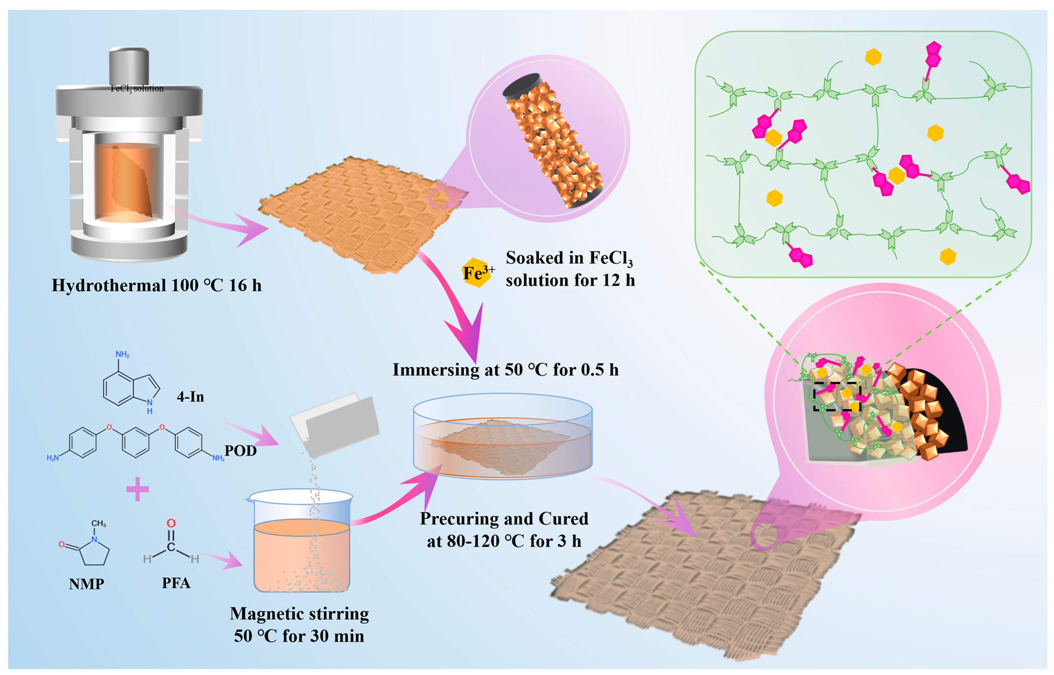
The first step of In-PHT/PEW/FeOOH@CF composite preparation was similar to IPFC. The In-PHT precursor solution was also obtained by the composition shown in Table 1. Unlike IPFC, In-PHT/PEW was mixed with 3 wt% PEW by vigorous stirring for 1 h and subsequent ultrasonic treatment for 30 min. Secondly, the FeOOH@CF was immersed in the In-PHT/PEW prepolymer solution and subsequently precured at 80–100 °C for 5–10 min. This impregnation–precuring cycle was repeated multiple times to build up the coating. The thickness of the coated composite was measured using a micrometer; the process was continued until the thickness measured on a single side reached a minimum of 0.38 mm. Finally, the prepared prepolymer In-PHT/PEW/FeOOH@CF should be finally cured at 200 °C for 2 h. The resultant sample was noted as IPEFC. The schematic diagram illustrates the fabrication procedure of IPFC and IPEFC (Figure 1).

2.4. Characterization

The surface micromorphology of CF, FeOOH@CF, IPFC, and IPEFC before and after wear was examined by field emission scanning electron microscopy (FESEM, FEI Quanta FEG-450, USA) with an accelerating voltage of 5.0 kV. The typical graphitized material structures of CF, FeOOH@CF, IPFC, and IPEFC were analyzed by Raman spectrometer measurements (Raman, Horiba Jobin-Yvon LabRAM HR800, France). The chemical composition and surface functional groups of FeOOH@CF were evaluated by the X-ray photoelectron spectroscopy (XPS, Kratos Axis Supra, UK) and Energy Disperse Spectroscopy (EDS, FEI verios 460, USA). The thermogravimetric analysis (TG-DSC, Netzsch TG-DSC, Germany) was performed to evaluate the thermal stability of In-PHT, Fe3+-In-PHT, Fe3+-In-PHT/PEW, IPFC, and IPEFC under N2 atmosphere.

2.5. Tribological and Mechanical Performance Testing

The rotating tribological tests were utilized to corroborate tribological property under different loading (1–4 N, 200 r/min) and diverse environments (i.e., dry, artificial seawater, and PAO friction) (MST-3000, Huahui, China). The tribology experimental samples (Ø10 mm) were fixed coaxially on a revolving disc, and the rotating friction was carried out by the friction pairs of steel ball (62 HRC, Ø4 mm) at a fixed position 3 mm away from the rotatable disk center. Before friction test, the friction pairs should be ultrasonically cleaned by soaking them in ethanol for 30 min. The electric universal testing machine (China, LD24. 204, Youhong, China) was utilized to estimate tensile property. The sample utilized for tensile performance test needed to be trimmed into a rectangular flake with 100 mm × 10 mm. The sample that touched both ends of fixtures was covered by a sheet of thick paper.

2.6. Self-Healing Test of IPEFC

The worn samples of IPEFC were prepared after tribological test (3 N, 300 r/min, 300 min). Then, the worn sample was placed on the heat stage and heated under 120 °C for 60 s. Tribological tests of healed samples were performed under the same condition to verify the effect of the repair process on the friction properties. And the optical microscopy (Zeiss Axio Observer.Z1m, Oberkochen, Germany) was used to measure the width of worn surfaces.

3. Results

3.1. Microstructure of FeOOH@CF

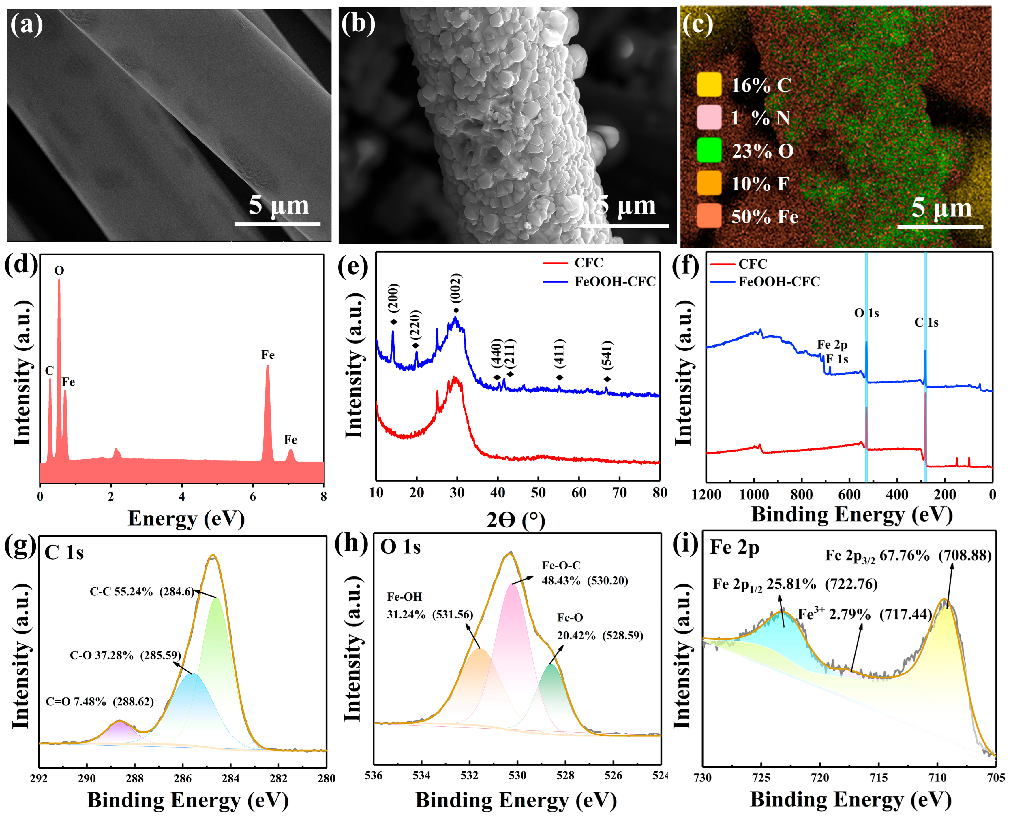
The growth of FeOOH nanoparticles on the CF surface is observed by different characterization methods. The SEM images of the microstructure of FeOOH@CF are provided in Figure 2a,b, which features a dense armor-like morphology. Figure 2c,d show the well dispersion and the considerable content of the Fe element. The X-ray photoelectron spectroscopy and XRD pattern both verify the successful preparation of the FeOOH nanoparticle layer. The peak at 25.2° in the XRD pattern corresponds to the (002) crystal plane of carbon material (Figure 2e). The peak intensity of FeOOH@CF is relatively lower than CF for the reason that the compact FeOOH nanoparticles produce a screening effect, leading to XRD detection-depth limitations. And the (200), (220), (440), (211), (411), and (541) peaks correspond to the β-FeOOH structure (PDF # 75-1594) [32].
The chemical bonding between FeOOH nanoparticles and CF was investigated by XPS. The Fe, O, and C elements can be obviously detected in the typical survey spectrum for FeOOH@CF and CF (Figure 2f). The C1s spectrum of FeOOH@CF mainly displays three characteristic peaks located at 284.6, 288.62, and 285.59 eV, appointing to the typical carbon peaks C-C, C=O, and C-O, respectively (Figure 2g). The O1 spectrum of FeOOH@CF is shown in Figure 2h, which exhibits three constituent peaks at 528.59 eV, 531.56 eV, and 530.20 eV, which are regarded as Fe-O, Fe-O-H, and Fe-O-C bonds, respectively. For the Fe2p spectrum, there are two obvious distinct peaks at 722.76 eV and 719.06 eV, corresponding to Fe2p3/2 and Fe2p1/2, respectively (Figure 2i). Notably, a shake-up satellite peak at 717.44 eV is observed in the Fe2p core-level spectrum, which is characteristic of Fe3+ in FeOOH nanoparticles [33]. The presence of Fe3+ cations with a coordinatively unsaturated surface environment is the prerequisite for forming “point-face” cation–π bonds with In-PHTs [22]. Collectively, these results provide strong evidence for the successful grafting of FeOOH nanoparticles onto CF.
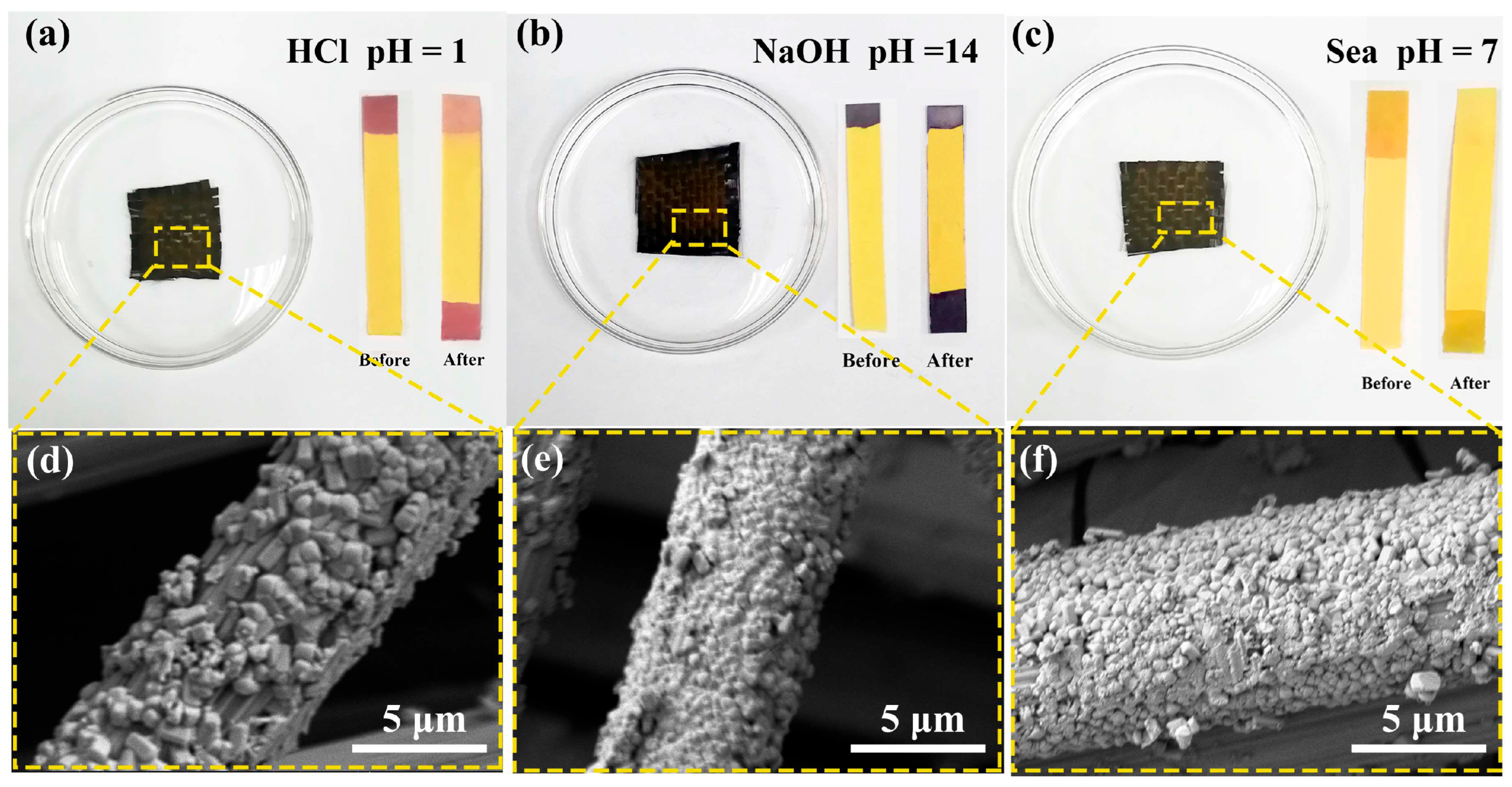
To further investigate the microstructure stability of FeOOH@CF, the surface morphologies of the sample are observed by FESEM after soaking in 1 M HCl, 1 M NaOH, and artificial sea solution under ultrasound for 24 h. The SEM images are shown in Figure 3. There are no visible differences between the microstructure of the three samples, as the FeOOH nanoparticles are still stable and riveting on the CF surface, which illustrates the stability of FeOOH@CF under harsh conditions.

3.2. Microstructure and Interlayer Characteristics of IPFC and IPEFC

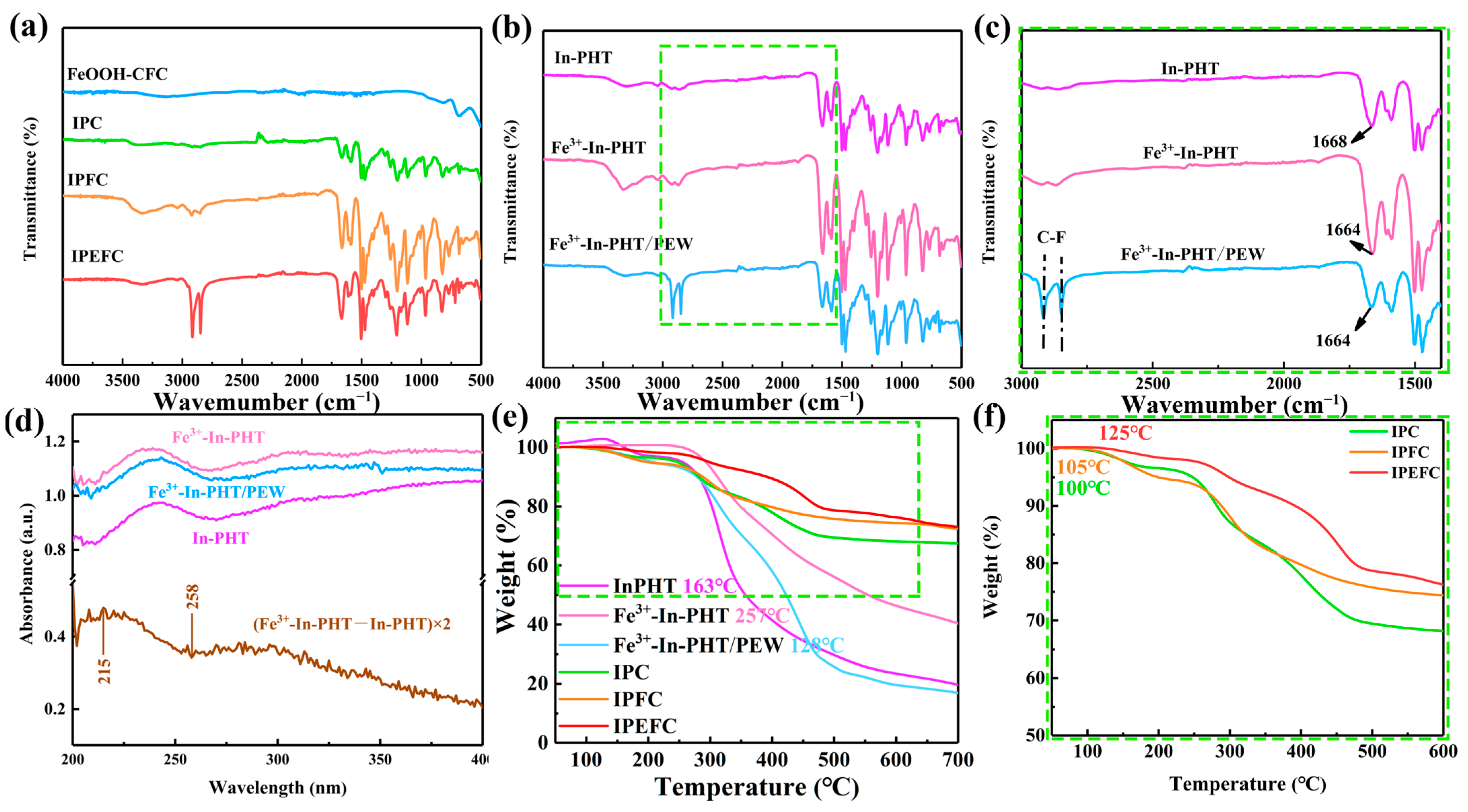
The Fe3+ is supported with the rigid transition layer composed of FeOOH nanoparticles, which provided a favorable condition for the cation–π bond formation between the In-PHT polymer matrix and FeOOH@CF. The FTIR and UV absorption spectra are exhibited to determine the efficient intermolecular cation–π interaction. There is only one absorption peak near 3450 cm−1, which belongs to the N-H stretching peak of the indole pyrrole ring, while the characteristic peak of the amino group gradually disappears after the reaction (Figure 4a). The weak peak indicates that the reaction of the amino group is almost finished (Figure 4a). In addition, the absorption peaks at 2918 and 2817 cm−1 are shown in Figure 4a. They are regarded as the anti-symmetric and symmetric spectra of the -CH2- vibrational stretch, respectively [26]. The absorption peaks at 1121 and 768 cm−1 correspond to the C-N absorption peaks, which indicated the formation of the triazine ring (Figure 4a,b) [26].
The local amplification FTIR spectra of diverse film samples from 1500 to 3000 cm–1 is provided in Figure 4c. As observed in the FTIR spectra of the In-PHT, the vibration absorption peak of N-H is detected at 1668 cm−1. After the embedding of Fe3+ into In-PHT, the vibration-absorption peak of N-H shifted to 1664 cm−1 (Figure 4c), which indicated the construction of cation–π interactions between In-PHT and Fe3+ [34,35]. As we anticipated, the N-H vibrational absorption peak does not return to its initial position after the addition of PEW, indicating that the formation of cation–π does not affect PEW. The UV-vis absorption spectra of different films are presented in Figure 4d, which reveals a pair of negative/positive intensity changes located at 215/258 nm, which is further evidence of the stabilized non-covalent interaction between Fe3+ and the indole rings (Figure 4d). That interaction is present in Figure 4a, which indicates that the FeOOH nanoparticles on the CF surface are still combined with In-PHT via the Fe3+–π bonding. The acquired composites are characterized by a thermogravimetric analyzer to prove the improvement of thermostability via the cation–π interaction in Fe3+-In-PHT. The higher thermal decomposition temperature observed for Fe3+-In-PHT results from the restricted segmental mobility imposed by the crosslinking network, where cation–π interactions between Fe3+ and the indole rings serve as physical crosslinks, enhancing interchain cohesion and raising the thermal degradation threshold, which is consistent with the elevated onset degradation temperature (Figure 4f) [36]. Compared with IPFC, IPEFC exhibits a higher thermal decomposition temperature and a slower loss rate (Figure 4e,f). The brilliant thermostability and outstanding tensile strength are essential advantages for wear-resistant CFRPs, which settled their sustaining usage period in harsh fields [18].
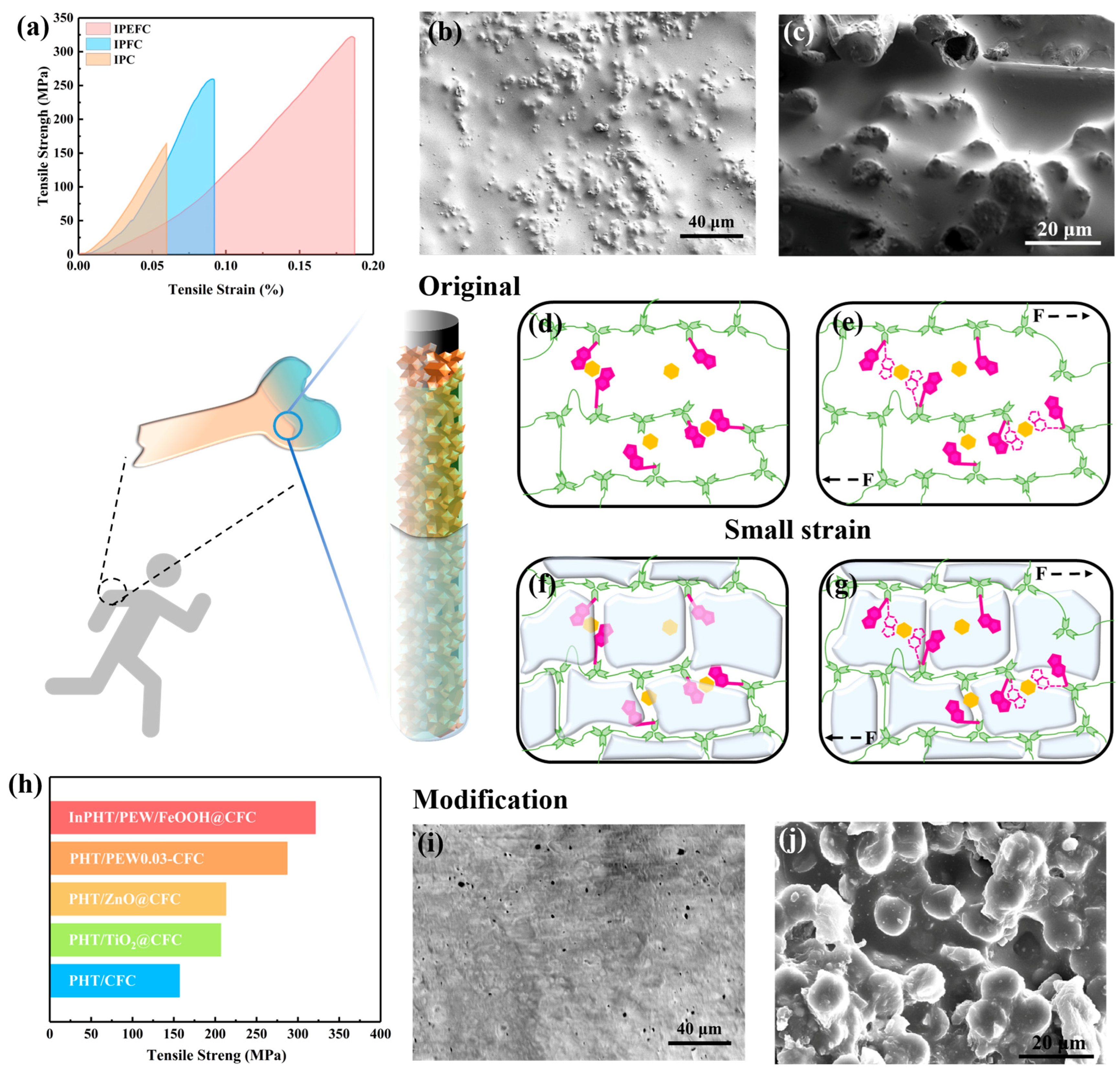
The “point-face” non-covalent interactions of cation–π bonds will form a large binding area between polymer networks and the nanolayer, and they will also form the compact interfacial bonding with the nanophase. And the synergism enhancement of physical and chemical interactions will avoid interfacial failure and the matrix yield, which contribute to the improvement of tensile strength. The positive effect of the tensile properties by Fe3+–π interactions are shown in Figure 5a; it exhibits an excellent tensile strength of IPEFC. The reason why the tensile strength of IPEFC is higher than IPFC is that the addition of PEW achieves the reduction of internal stress. The development of internal stress due to the thermal shrinkage of PHT-CFRPs occurs during the cooling period from the cure temperature to the room temperature. The PEW with a low melting point undergoes a rapid-phase transition to a solid phase at room temperature after curing at high temperature [37], which avoids the rapid shrinkage of the polymer matrix and relieves stress concentration. After the addition of PEW, the surface smooth-out, due to the PEW mimic, in the cartilage and cover of the bone, which consist of In-PHT and FeOOH@CF (Figure 5b). But the SEM images of IPFC surface characteristics display many micro-nano particles, like the bone tissue without cartilage (Figure 5b). The mechanism for tensile process at small strains is presented in Figure 5d–g. During the slight stretch, the free chains are fixed by generating cation–π interactions between the cross-link of the indole groups and FeOOH, resulting in the higher tensile strength. After the tensile strength test, the fracture microstructure is observed by scanning electron microscopy, while the SEM images of fracture morphology are shown in Figure 5c,j and Figure S1b. It is remarkable that the residual matrix layers of IPEFC are attached tightly to the CF surface (Figure 5j). That may be contributed to the improvement of interface adhesion by rigid and flexible interfaces. But, in the fracture of In-PHT/CF (IPC) (Figure S1b) and IPFC, there appear several pores, and the IPFC without PEW shows that the cavity is completely separated by CF (Figure 5c), and that there is a non-covalent cation–π dissociation under large strain (Figure S2). Nevertheless, the fractured part of IPEFC is still completely filled and adhered with PEW. Hence, compared to the other report composites, the tensile strength of IPEFC is higher than the other recycled PHT polymer composites (Figure 5h). Combined with the results shown in Figure 3 and Figure 4, and the above analysis, there are three reasons for the improvement of tensile property:
(1)
A physical interaction is constructed by the excellent wettability of the stable FeOOH nanoparticles’ multiscale nanostructure to In-PHT;
(2)
A strong chemical Fe3+–π bonding was formed between FeOOH@CF and In-PHT;
(3)
The stress concentration of interface is relieved by a PEW soft lubricating additive.

3.3. Tribological Properties of the IPFC and IPEFC Composites

In order to verify the possibility of IPFC as a wear-resistant material, we conducted friction tests on samples obtained with different proportions from Table S1, and the friction coefficient curves obtained are shown in Figure S3. Even at lower load of 2 N and slower speed of 200 r/min, the friction coefficients of 1–4 N samples are still around 0.50. According to our previous work, the FeOOH nanoparticles that modified CPRFs maintain a friction coefficient of 0.45 at higher loads [28]. Sample 5 achieves the improvement of friction performance, and the average friction coefficient is reduced to 0.32 under low loads, which indicates that this ratio has good wear resistance.
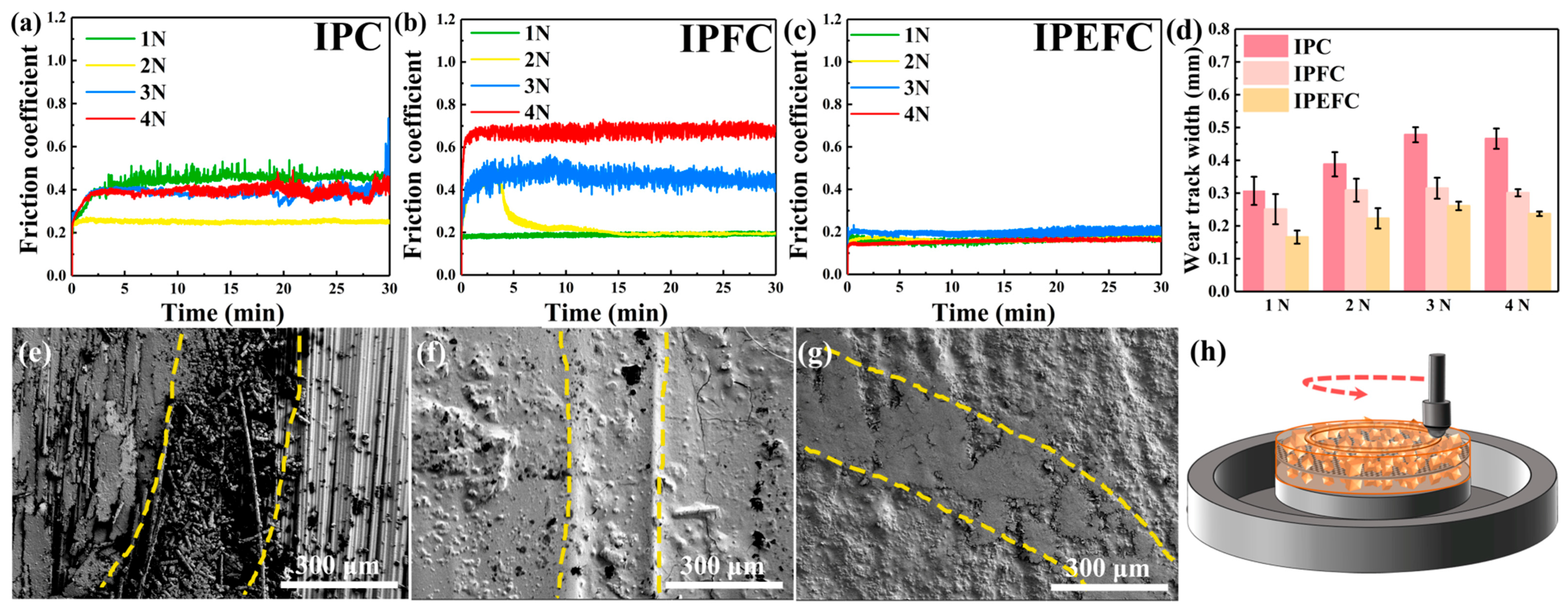
Figure 6a–c show the friction coefficient curves of varying composites with sliding speeds of 200 r/min and 1–4 N loads under dry conditions. The friction coefficient curve of IPC has significant floating. After building a rigid transition layer, the stability of friction coefficient is improved (Figure 6b), keeping it around 0.30. And an obvious ameliorate happens after the introduction of PFW, while the friction coefficient of IPEFC shows a significant decrease to 0.20 (Figure 6c). Apparently, it is more stable than the other samples’ coefficient. The wear width of the IPEFC dramatically decreases by 50% (Figure 6d) compared to the IPC. The wear width of IPFC is also lower than the IPC but higher than the IPEFC, which further confirmed that the IPEFC possesses optimal wear resistance. As provided in Figure 6e, the wear scar surface of IPC after the tribological test exhibits either the chipping away of CF, or the surface layer debonding. With the existence of a rigid transition layer, it bears most of the load, while the wear debris of IPFC decreases obviously. In comparison, there are no CFs pulling out from the wear scar surfaces of IPFC and IPEFC, and the wear width tends to narrow (Figure 6f,g).
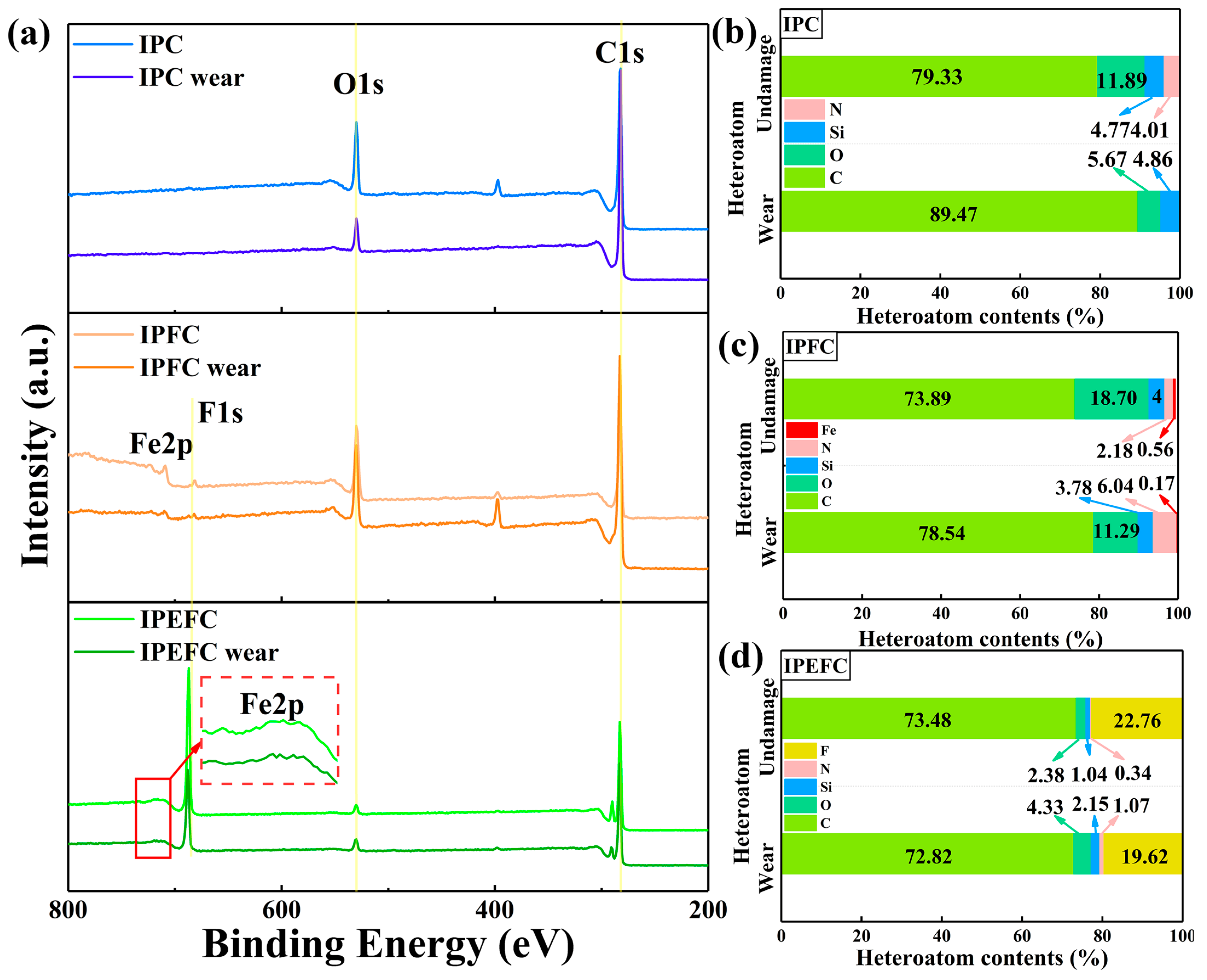
The contribution of non-covalent bonds to the wear resistance behavior of IPEFC is reflected in the formation of a smooth wear surface, where the repeated formation of cation–π bonds under shear force effectively suppresses the initiation of microcracks. As confirmed by XPS analysis, the Fe2p core-level spectrum of IPEFC after friction testing still shows a signal at 719.5 eV (Figure 7), indicating the sustained presence of Fe3+ for the reformation of these bonds. This dynamic process enables the service life of IPEFC to be significantly longer than that of IPC and IPFC (Figure S4). As shown in Figure S4, when the friction test continues to 600 min, the friction coefficient of IPEFC still remains around 0.20. But the friction coefficient of IPFC surges to 0.45 when the friction test lasted for 205 min. (Figure S4). During continuous friction, a significant number of reversible cation–π bonds have broken and reformed non-covalent interactions with newly approaching Fe3+, thereby prolonging the service life of IPFC. However, prolonged wear results in stress concentration at the interface, which can lead to the gradual formation of microcracks within the matrix. Therefore, IPFCs that lack a PEW-alleviated layer exhibit inferior durability when compared to IPEFC.
The cation–π interaction after friction is investigated by XPS (Figure 7). The CF surface is mainly constituted by C elements, and the atom percentage of C maintains around 80%. But the O atom percentage of IPEFC decreases significantly, which is ascribed to the embedded of PEW (Figure 7d). The nitrogen is derived from nitric functional groups by the original sizing agent, which could not be completely removed by the acetone solution [38,39]. It is notable that IPFC has a very weak F peak, which may be caused by the preparation of FeOOH nanoparticles using NaF during the experimental process. But the strong F peak existence of IPEFC is attributed to the PEW, and the F contents presented on IPEFC do not significantly reduce after friction, indicating that fewer PEWs are consumed during friction process. The less consumption of PEW guarantees a sufficient repair agent, which is more conducive to the self-healing for PHT-CFRPs.
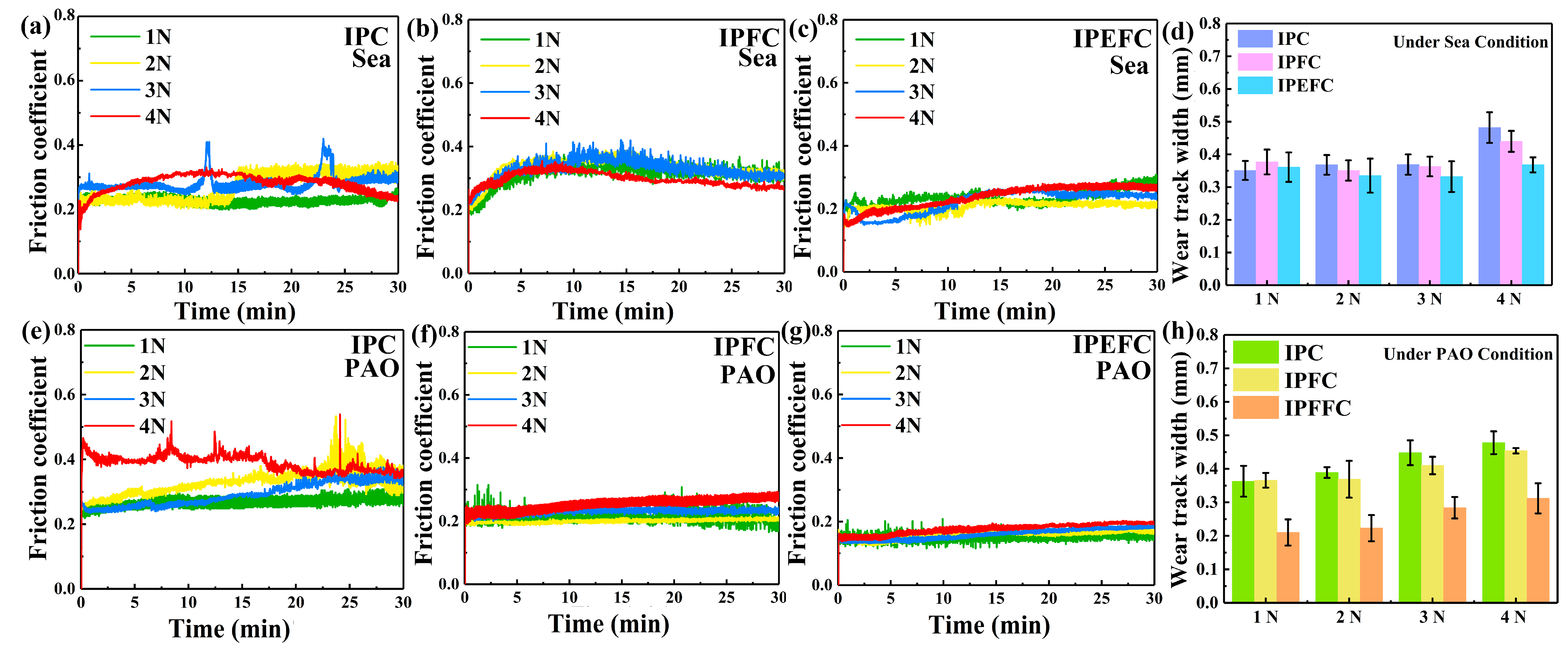
Since In-PHT has good stability under extreme environment [26], in order to verify that the cation–π interaction is beneficial to tribological characteristic, we carried out the friction experiment with the 1–4 N load and 200 r/min rotational speed under artificial seawater (Figure 8a–d), PAO (Figure 8e–h), and strong alkali conditions (pH = 14). Compared with IPEFC, the friction coefficient curves of IPFC (Figure 8b,f) and IPC (Figure 8a,e) fluctuate severely and increase significantly in the later period of friction. As shown in Figure 8c,g, the addition of the PEW significantly decreases the running period, while the friction coefficient of IPEFC tends to stabilize quickly. Based on the synergistic enhancement of rigid flexible transition layers between interfaces, the smooth and stable friction coefficient curves of IPEFC are acquired under artificial seawater and PAO conditions (Figure 8c,g), even under strong alkali conditions, the friction coefficient curves of IPEFC still have a downward trend (Figure S5). The friction coefficient of IPEFC remains around 0.20 (Figure 8c,g). This is attributed to the non-covalent interaction between the Fe3+ and indole group from In-PHT branch chain, which hinders the propagation of matrix cracks to the F/M interface. In addition, the cracks are effectively blocked and deflected by the rigid transition layer, avoiding the occurrence of interface failure. Therefore, the scratch width of IPEFC is relatively narrow (Figure 8d,h). The synergistic reinforcement and toughening of the interface by the rigid and flexible transition layer effectively protect the IPEFC surface from continuous friction damage and strong alkali corrosion.
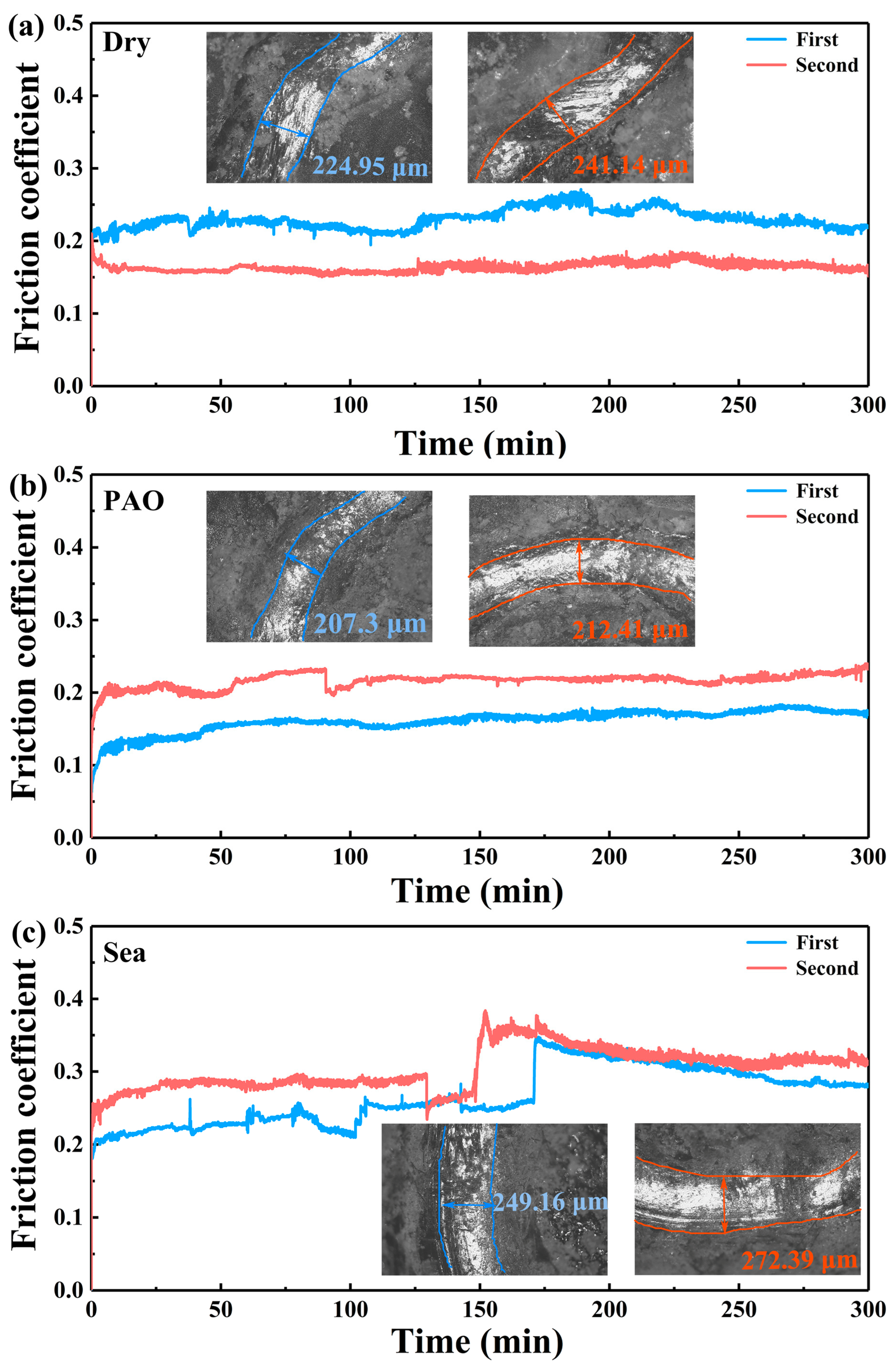
The flexible transition layer formed by the PEW not only relieves interlayer stress concentration and improves the strength and toughness of the F/M interface of IPEFC, but it also endows IPEFC with self-healing performance, enabling the modified surface to be quickly repaired at 120 °C. The process of self-healing of worn scar under 120 °C is provided in Figure S6 and Video S1. This owes to the low melting point of PEW at 120 °C, a quick phase separation of PEW between the interlayer of IPEFC upon the thermal trigger [37]. Driven by stress relaxation, the molten PEW chains migrate directionally toward the worn scar, filling the surface defects and healing the damaged region upon cooling (Figure S7) [40]. The friction coefficient curve before and after self-healing of IPEFC obtained by 300 min friction test under different conditions are shown of Figure 9a–c. The friction coefficient curve of IPEFC is steady under dry and PAO conditions, even after self-healing (Figure 9a,b). Under artificial seawater, the friction coefficient curve of IPEFC slightly rises, which is owed to the seawater evaporation under frictional heat. Fortunately, with the addition of PEW, the curve rapidly shifted from the running-in period to the stable period. The wear track optical images of IPEFC after friction are performed in Figure 9, the wear track width increased slightly with the time prolonging, which stabilizes around 250 μm.
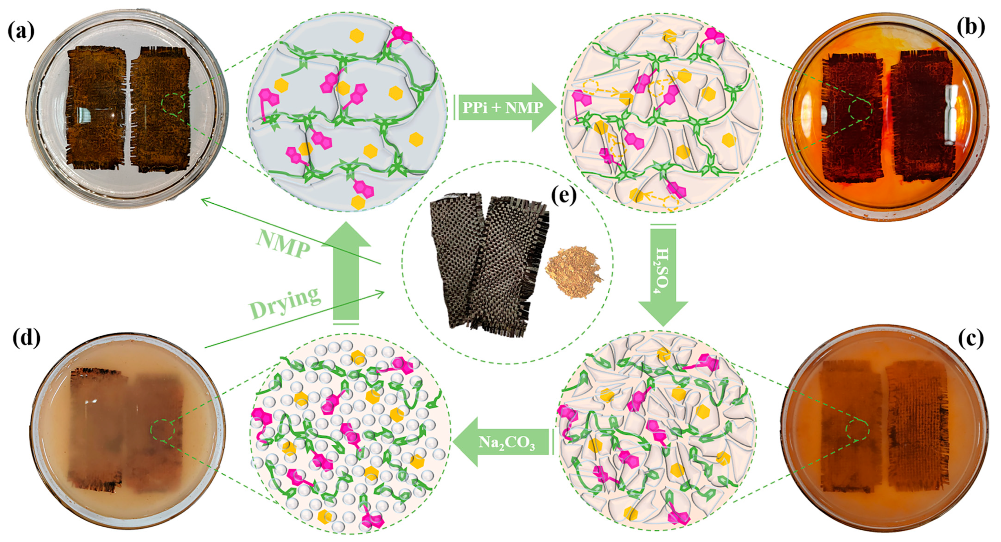
The improvement of interlayer interactions has no effect on the nondestructive recycling of carbon fiber. There are four stages of the IPEFC recycling process: Firstly, the IPEFC immerses in NMP solution of PPi (pH ≈ 2) under 50 °C for 12 h. Owing to the strong coordination affinity of pyrophosphoric acid (PPi) toward Fe3+, the Fe3+ cations are effectively captured from the composite system, which disrupts the cation–π interactions between indole groups and Fe3+ [41]. Consequently, the captured Fe3+ is dissolved in NMP, causing the solution to turn orange (Figure 10b). Secondly, the samples should be put into the H2SO4 solution (pH ≈ 1) for 36 h, where the IPEF sizing covered on CF decomposes gradually, the PEW emerges in solution, and the solution becomes cloudy (Figure 10c). Thirdly, sodium carbonate solution and recovery of the pH value of the solution should be added to Sample 7 (Figure 10d). Finally, the precipitate is collected and dried for 24 h under 50 °C (Figure 10e).

4. Conclusions

In conclusion, the FeOOH@CF reinforced In-PHT composites with durable wear resistant and efficient self-healing, which were obtained by the interaction of Fe3+-indole cation–π and the construction of FeOOH nanoparticles layer. The tensile properties enhanced to 322 MPa, owing to the improvement of interfacial bonding. Due to the introduction of the lubricating-phase PEW, IPEFC obtained a narrow wear scar width of 0.16 μm and demonstrated outstanding durability with the long-term friction coefficient lower to 0.15. An outstanding self-healing property was proved via a repeated tribological test, and the friction coefficient remained stable at approximately 0.20 even after multiple self-healing. In addition, valuable CF could be totally recycled from IPEFC. This durable IPEFC with self-healing was more adaptable to the wear-resistant application in demanding conditions and promoted the advance of a circulation economy.

Supplementary Materials

The following supporting information can be downloaded at: https://www.mdpi.com/article/10.3390/pr14172708/s1, Figure S1: The SEM images of (a) IPC surface and (b) fracture morphology; Figure S2: The mechanism for the tensile behaviors: at large strains of (a) IPFC and (b) IPEFC; Figure S3: Friction coefficient of IPFC samples with different proportions of FeCl3·(H2O) under 2 N, 200 r/min; Figure S4: Long-time friction coefficient of IPC, IPFC and IPEFC under 2 N, 200 r/min; Figure S5: Comparison of friction coefficient of (a) IPC, (b) IPFC and (c) IPEFC under strong alkali condition condition; Figure S6: Self-healing image of wear scar after being heated at 120 °C after abrasion; Figure S7: Self-healing mechanism of the IPEFC; Table S1: The reaction ratio for FeOOH nanoparticles layer growthing; Video S1: The whole wear track self-healing process of IPEFC upon 120 °C for 60 s.

Author Contributions

Conceptualization, H.S.; Validation, X.L.; Writing—original draft, X.L.; Writing—review and editing, X.J.; Supervision, H.S.; Project administration, X.L.; Funding acquisition, X.L. All authors have read and agreed to the published version of the manuscript.

Funding

This research was funded by Natural Science Basic Research Program of Shaanxi (Program No. 2026JC-YBQN-0673), Natural Science Foundation of Xi’an (Program No. 2025JH-ZRKX-0634) and Natural Science Basic Research Program of Shaanxi (Program No. 2026JC-QYCX-046).

Data Availability Statement

The original contributions presented in this study are included in the article. Further inquiries can be directed to the corresponding author.

Conflicts of Interest

The authors declare no conflicts of interest.

Abbreviations

The following abbreviations are used in this manuscript:
PHTpoly(hexahydrotriazine)
In-PHTindole-based poly(hexahydrotriazine)
PEWpolyethylene wax
PHT-CFRPscarbon fiber reinforced poly(hexahydrotriazine) composites
CNTcarbon nanotubes
NMPN-methyl-2-pyrrolidone
4-In4-aminoindole
POD4,4′-(1,3-phenylenedioxy) dianiline
FeCl3·6H2OFerric chloride hexahydrate
NH4Fammonium fluoride
PPipyrophosphatic acid
H2SO4concentrated sulfuric acid
PFAparaformaldehyde
PPipyrophosphoric acid

References

  1. Li, X.Q.; Jia, X.H.; Song, H.J.; Chen, H.; Sun, S.J. Carbon nanotubes and carbon fiber filled polyhexahydrotriazine composites: Assessing the tribological and mechanical properties. Polym. Eng. Sci. 2025, 65, 2080–2092. [Google Scholar] [CrossRef] [Scilit]
  2. Min, C.Y.; Su, Y.X.; Yu, H.; Liang, H.Y. Synergistic strengthening and toughening of the recyclable polyhexahydrotriazine (PHT) crosslinked polyimide by constructing rigid-flexible structure for tribology application. Tribol. Int. 2026, 213, 111098. [Google Scholar] [CrossRef] [Scilit]
  3. Ben Brayek, B.E.; Sayed, S.; Mînzu, V.; Tarfaoui, M. Machine Learning Predictions for the Comparative Mechanical Analysis of Composite Laminates with Various Fibers. Processes 2025, 13, 602. [Google Scholar] [CrossRef] [Scilit]
  4. Kim, H.J.; Ha, D.; Choi, H.; Yun, G.J. Multiscale fatigue life prediction model for CFRP laminates considering the mechanical degradation of its constituents and the local stress concentration of the matrix. Compos. Struct. 2024, 349–350, 118519. [Google Scholar] [CrossRef] [Scilit]
  5. Xie, L.; Lu, Y.; Zhang, K. Strong, Reprocessable and Chemically Recyclable Biomass-Derived Thermoset Materials Enabled by Dynamic Covalent Polybenzoxazine Networks. Adv. Funct. Mater. 2026, 36, e75273. [Google Scholar] [CrossRef] [Scilit]
  6. Jeong, Y.; Han, J.; Lee, S.; Kim, G.; Kim, D. High-performance and sustainable carbon fiber-reinforced polymers enabled by β-amino sulfone-based covalent adaptable networks. Chem. Eng. J. 2026, 533, 174813. [Google Scholar] [CrossRef] [Scilit]
  7. Gulyaev, A.I.; Sbitneva, V.S.; Valueva, I.M.; Zelenina, V. The Influence of Temperature Factors on Adhesion Strength of Fiber–Matrix in Carbon-Fiber-Reinforced Polyimide Composite. Polym. Sci. Ser. D. 2025, 18, 497–502. [Google Scholar] [CrossRef] [Scilit]
  8. Lin, Z.; Jia, X.H.; Yang, J.; Li, Y.; Song, H.J. Interfacial modification and tribological properties of carbon fiber grafted by TiO2 nanorods reinforced novel depolymerized thermosetting composites. Compos. Part A Appl. Sci. Manuf. 2020, 133, 105860. [Google Scholar] [CrossRef] [Scilit]
  9. Gamil, M.; Farouk, M.W.; Oqail, A.A.; Mohamed, A.O.; Ghaith, A.H. Dynamic mechanical thermal analysis (DMTA) of the hybrid epoxy/carbon-fibers nanocomposites for satellite structures. Sci. Rep. 2026, 16, 12720. [Google Scholar] [CrossRef] [Scilit] [PubMed]
  10. Ma, J. Structural and mechanical performance analysis of hexagonal boron nitride reinforced carbon fiber/epoxy hybrid composites for bicycle frame applications. J. Ceram. Process. Res. 2026, 27, 366–373. [Google Scholar] [CrossRef]
  11. Haider, R.M.; Singh, K.P.; Sharma, K. Effect of graphene on mechanical characteristics of carbon fiber/epoxy nanocomposites. MRS Adv. 2025, 10, 2388–2395. [Google Scholar] [CrossRef] [Scilit]
  12. Min, C.; Yang, Y.; Liang, H.Y.; Siddique, A.; Xu, Z.; Liang, H. Mechanical and Tribological Enhancement of Carbon Fiber/Poly(Hexahydrotriazine) Composites via Modulus Gradient Zinc Oxide@Zeolitic Imidazolate Framework-8 Array Interphase. Polym. Compos. 2025, 47, 9609–9624. [Google Scholar] [CrossRef] [Scilit]
  13. Chen, J.; Sun, C.; Han, Z.; Zhang, Y.; Yang, F. Rapidly synthesizing magneto-thermal adjustable high entropy alloy nanoparticles on carbon fiber surface for enhancing electromagnetic wave absorption, thermal conductivity and interface compatibility of composites. Chem. Eng. J. 2024, 498, 155351. [Google Scholar] [CrossRef] [Scilit]
  14. Bisoyi, S.; Salins, S.S.; Sachidananda, K.H. Enhancing mechanical properties of carbon fiber-reinforced composites via acid activation. Discov. Appl. Sci. 2025, 7, 443. [Google Scholar] [CrossRef] [Scilit]
  15. Negrov, A.D.; Putintsev, Y.V.; Knyazev, V.E.; Aleksey, I.G.; Denis, A.V. Influence of chemical functionalization of carbon fiber on interfacial interactions and property enhancement of PTFE based composites. J. Mech. Sci. Technol. 2026, 40, 2015–2024. [Google Scholar] [CrossRef] [Scilit]
  16. Fu, J.; Ao, Y. Enhanced interfacial properties of carbon fiber/epoxy composites by coating varying molecular chain lengths of polyetheramine at interphase. Compos. Commun. 2026, 64, 102805. [Google Scholar] [CrossRef] [Scilit]
  17. Ayyagari, S.; Al-Haik, M.; Ren, Y.; Abbott, A.; Trigg, E.B.; Zheng, B.; Koerner, H. Metal organic frameworks modification of carbon fiber composite interface. Compos. Part B Eng. 2021, 224, 109197. [Google Scholar] [CrossRef] [Scilit]
  18. Lin, Z.; Jia, X.H.; Yang, J.; Li, Y.; Wang, S.Z.; Song, H.J. High structural stability of colored carbon fiber cloths modified by FeOOH. Appl. Surf. Sci. 2021, 545, 148994. [Google Scholar] [CrossRef] [Scilit]
  19. Zhang, H.; Zhang, H.R.; Zhang, X.; Sun, T.; Liang, M.; Chen, Y.; Heng, Z.; Zou, H. In-situ self-assembled block copolymer nanowires on high-modulus carbon fibers surface for enhanced interfacial performance of CFRPs. Chem. Eng. J. 2023, 451, 138583. [Google Scholar] [CrossRef] [Scilit]
  20. Fan, Z.; Wang, Y.; Jeon, J.S.; Kim, D.; Fang, Y.; Shi, X.; Luo, Z.; Ohkita, H.; Wang, B. Enhancing multiwalled carbon nanotubes/poly(amide-imide) interfacial strength through grafting polar conjugated polymer on multiwalled carbon nanotubes. Surf. Interfaces 2022, 32, 102130. [Google Scholar] [CrossRef] [Scilit]
  21. García, J.M.; Jones, G.O.; Virwani, K.B.; Mccloskey, D.; Boday, D.J.; Huurne, G.M.; Horn, H.W.; Coady, D.J.; Bintaleb, A.M.; Alabdulrahman, A.M.S.; et al. Recyclable, Strong Thermosets and Organogels via Paraformaldehyde Condensation with Diamines. Science 2014, 344, 732–735. [Google Scholar] [CrossRef] [Scilit] [PubMed]
  22. Paul, P.; Saha, S.; Biradha, K. Differentiating aliphatic and aromatic alcohols using triazine-based supramolecular organogelators: End group-specific selective gelation with chain length of alcohols. Soft Matter 2024, 20, 2568–2574. [Google Scholar] [CrossRef] [Scilit] [PubMed]
  23. Yamada, S.J. Cation-π Interactions in Organic Synthesis. Chem. Rev. 2018, 118, 11353–11432. [Google Scholar] [CrossRef] [Scilit] [PubMed]
  24. Gao, Z.; Zhang, A.J.; Zhang, Z.; Mu, B.; Tian, W. Controllable Cation-π Chemistry: Modular Monomer Design, Directed Supramolecular Assembly, and Multifunctional Applications. Acc. Chem. Res. 2026, 59, 557–569. [Google Scholar] [CrossRef] [Scilit] [PubMed]
  25. Xie, F.; Shang, Y.; Wei, H.; Zhuo, L.; Zhao, Y. Interfacial cation-π anchoring via benzimidazole for synergistic pollutant removal in polyimide@Zeolitic Imidazolate Framework-8 composite membranes. Chem. Eng. J. 2026, 528, 172428. [Google Scholar] [CrossRef] [Scilit]
  26. Guan, X.F.; Ma, Y.C.; Yang, L.; Xu, Y.W.; Yang, L.; Huang, Y.; Diangha, T.P.; Chang, G. Unprecedented toughening high-performance polyhexahydrotriazines constructed by incorporating point-face cation-π interactions in covalently crosslinked networks and the visual detection of tensile strength. Chem. Commun. 2020, 56, 1054–1057. [Google Scholar] [CrossRef] [Scilit] [PubMed]
  27. Yu, J.P.; Chen, Y.H.; Xu, Y.; Yuan, R.; Huang, Y.; Ma, T.N.; Lan, Y.; Yang, L. Facile Construction of Recyclable and Toughened Polymer Composites via Slip-Transfer Effect of Cation-π Interactions on Nanofiller. ACS Appl. Polym. Mater. 2025, 7, 7122–7131. [Google Scholar] [CrossRef] [Scilit]
  28. Lin, Z.; Yang, J.; Jia, X.H.; Li, Y.; Song, H.J. Polydopamine/FeOOH-modified interface in carbon cloth/polyimide composites for improved mechanical/tribological properties. Mater. Chem. Phys. 2020, 243, 122677. [Google Scholar] [CrossRef] [Scilit]
  29. Li, X.; Jia, X.; Yang, J.; Yong, L.; Lin, H.; Song, H. Synergism of non-covalent interaction and ZIF-8@GO to improve tribological and mechanical properties of carbon fiber reinforced recyclable indole-based poly(hexahydrotriazine) composites. Polym. Compos. 2023, 45, 4151–4163. [Google Scholar] [CrossRef] [Scilit]
  30. Das, S.J.; Vasilyev, G.; Martin, P.; Zussman, E. Bioinspired Cationic-Aromatic Copolymer for Strong and Reversible Underwater Adhesion. ACS Appl. Mater. Interfaces 2022, 14, 26287–26294. [Google Scholar] [CrossRef] [Scilit] [PubMed]
  31. Geng, H.M.; Zhang, P.Y.; Peng, Q.Y.; Cui, J.W.; Hao, J.C.; Zeng, H.B. Principles of Cation−π Interactions for Engineering Mussel-Inspired Functional Materials. Acc. Chem. Res. 2022, 55, 1171–1182. [Google Scholar] [CrossRef] [Scilit] [PubMed]
  32. Han, J.; Huang, L.; Wu, J.; Chen, H.; Pan, J.; Han, J.; Ma, F.; Li, J.; Cong, H. Robust preparation of catalytic PEI@FeOOH fiber membrane for efficient dye degradation. J. Water Process Eng. 2024, 57, 104638. [Google Scholar] [CrossRef] [Scilit]
  33. Du, Y.; Liu, Y.; Wei, X.; Zhao, F.; Wang, T.; Li, Z.; Shi, E.; Liu, S.; Fan, C.; Yang, Y.; et al. Reaction enhanced surface segregation method via phytic acid and Fe3+ complexation for high-performance nanofiltration membrane. J. Membr. Sci. 2026, 740, 124953. [Google Scholar] [CrossRef] [Scilit]
  34. Wang, Z.; Chen, J.; Di, Y.; Luo, H.; Liu, J. Strong transition metal/Schiff Base-benzene interactions enhance strength, toughness, and recyclability of elastomers for sport applications. Chem. Phys. 2026, 604, 113087. [Google Scholar] [CrossRef] [Scilit]
  35. Wang, M.; Gao, H.; Jiang, J.; Gao, L.; Hu, G. Relationship between degree of microphase separation, crosslinking density, and anticorrosive performance of casting polyurethane coatings. J. Coat. Technol. Res. 2024, 22, 281–297. [Google Scholar] [CrossRef] [Scilit]
  36. Zhang, Y.M.; Zhu, W.; Qu, W.J.; Zhong, K.P.; Chen, X.P.; Yao, H.; Wei, T.B.; Qi, L. Competition of cation–π and exo-wall π-π interactions: A novel approach to achieve ultrasensitive response. Chem. Commun. 2018, 54, 4549–4552. [Google Scholar] [CrossRef] [Scilit] [PubMed]
  37. Zhang, L.Z.; Liu, Z.H.; Wu, X.L.; Guan, Q.B.; Chen, S.; Sun, L.J.; Guo, Y.; Wang, S.; Song, J.; Jeffries, E.M.; et al. A Highly Efficient Self-Healing Elastomer with Unprecedented Mechanical Properties. Adv. Mater. 2019, 31, 1901402. [Google Scholar] [CrossRef] [Scilit] [PubMed]
  38. Shu, Q.; Bi, Y.; Nan, Z.; Zhang, H.; Li, H.; Chen, B. Enhanced durability and self-healing properties of palygorskite-based superhydrophobic coatings. Colloids Surf. A Physicochem. Eng. Asp. 2023, 663, 130981. [Google Scholar] [CrossRef] [Scilit]
  39. Zhou, L.F.; Zhou, L.; Kang, M.; Zhao, X.L.; Chang, G.L.; Chen, M. Tough non-covalent adaptable networks: Cation-π cross-linked rigid epoxy. Polymer 2022, 243, 124626. [Google Scholar] [CrossRef] [Scilit]
  40. Peng, L.M.; Xu, Z.; Wang, W.Y.; Zhao, X.; Bao, R.Y.; Bai, L.; Ke, K.; Liu, Z.Y.; Yang, M.B.; Yang, W. Leakage-Proof and Malleable Polyethylene Wax Vitrimer Phase Change Materials for Thermal Interface Management. ACS Appl. Energy Mater. 2021, 4, 11173–11182. [Google Scholar] [CrossRef] [Scilit]
  41. Chang, G.J.; Wang, C.; Du, M.Q.; Liu, S.Y.; Yang, L. Metal-coordination crosslinked N-polyindoles as recyclable high-performance thermosets and nondestructive detection for their tensile strength and glass transition temperature. Chem. Commun. 2018, 54, 2906–2909. [Google Scholar] [CrossRef] [Scilit] [PubMed]
Figure 1. Schematic diagram of the procedure for the fabrication of IPFC and IPEFC composites.
Processes 14 02708 g001
Figure 2. The SEM images of (a) CF and (b) FeOOH@CF. (c,d) Elemental mappings and EDS of FeOOH@CF. (e) XRD pattern of CF and FeOOH@CF. (f) The XPS spectra results of FeOOH@CF and CF. The XPS wide-scanning spectra of (g) C 1s, (h) O 1s, and (i) Fe 2p spectrum of FeOOH@CF.
Processes 14 02708 g002
Figure 3. The pH value comparison of FeOOH@CF after soaking in (a) 1 M HCl for 24 h, (b) 1 M NaOH for 24 h, (c) artificial sea water for 24 h. The SEM images of FeOOH@CF after soaking in (d) 1 M HCl, (e) 1 M NaOH, (f) artificial sea water under room temperature.
Processes 14 02708 g003
Figure 4. (a) The FTIR spectra of different samples; (b) In-PHT, Fe3+-In-PHT, and Fe3+-In-PHT/PEW film samples; (c) Local amplification FTIR spectra of different film samples (1500–3000 cm−1); (d) UV-vis absorption spectra of different film samples; (e) TG of different samples; and (f) the local amplification of TG results for different samples.
Processes 14 02708 g004
Figure 5. Inspiration of the cation–π-based In-PHTs by the structure of bone. (a) Tensile strength of In-PHT/CF, IPFC, and IPEFC. SEM images of (b) IPFC-surface characteristic. (c) The fracture morphology of modified IPFC. (dg) The mechanism for the tensile process: at small strains of IPFC and IPEFC. (h) Comparison of tensile strength of recycle PHT polymer composites reported in the literature: PHT/TiO2@CFC [8], PHT/CFC [21], PHT/ZnO@CFC, PHT/PEW0.03-CFC [29]. (i) SEM images of IPEFC surface characteristic like the bone tissue covered with cartilage. (j) The fracture morphology of modified IPEFC.
Processes 14 02708 g005
Figure 6. Comparison of friction coefficient of (a) IPC, (b) IPFC, and (c) IPEFC under dry friction condition (200 r/min, 1–4 N) and (d) wear width between different samples. The SEM images of worn surface of (e) IPC, (f) IPFC, and (g) IPEFC. (h) The tribological mechanism of IPFC.
Processes 14 02708 g006
Figure 7. (a) Wide-scan survey XPS spectra of IPC, IPFC, and IPEFC before and after wear. Surface element compositions of (b) IPC, (c) IPFC, and (d) IPEFC before and after wear.
Processes 14 02708 g007
Figure 8. Comparison of friction coefficient of (a) IPC, (b) IPFC, and (c) IPEFC under sea condition (200 r/min, 1–4 N) and (d) wear width between different samples. Comparison of friction coefficient of (e) IPC, (f) IPFC and (g) IPEFC under PAO oily condition (200 r/min, 1–4 N) and (h) wear width between different samples.
Processes 14 02708 g008
Figure 9. Comparison of friction coefficient and optical microscope images of IPEFC samples before and after self-healing (120 °C, 60 s) under (a) dry condition, (b) PAO condition, (c) artificial seawater condition (3 N, 300 r/min, 300 min).
Processes 14 02708 g009
Figure 10. Recycling status of IPEFC: (a) the physical picture of IPEFC and its structure before recycling; (b) the physical picture of IPEFC and its structure immersed in PPi under 50 °C for 12 h; (c) the physical picture of IPEFC and its structure immersed in H2SO4 for 36 h; (d) the physical picture of IPEFC and its structure after neutralization; (e) the powder and CF collected after drying.
Processes 14 02708 g010
Table 1. The constituent and synthesis conditions of In-PHT solution.
ChemicalContent
POD0.008 g
4-In0.001 g
NMP16 mL
PFA30 μL
The temperature of stirring50 °C for 30 min
Disclaimer/Publisher’s Note: The statements, opinions and data contained in all publications are solely those of the individual author(s) and contributor(s) and not of MDPI and/or the editor(s). MDPI and/or the editor(s) disclaim responsibility for any injury to people or property resulting from any ideas, methods, instructions or products referred to in the content.