Article

Deformation Mechanism and Control Strategies of Gob-Side Entry Retaining by Roof Cutting in Ultra-Deep Coal Mines

1
Huaneng Coal Technology Research Co., Ltd., Beijing 100070, China
2
Consulting Center of China National Coal Association, Beijing 100013, China
*
Authors to whom correspondence should be addressed.
Processes 2026, 14(16), 2605; https://doi.org/10.3390/pr14162605
Submission received: 29 June 2026 / Revised: 6 August 2026 / Accepted: 13 August 2026 / Published: 16 August 2026

Abstract

Gob-side entry retaining by roof cutting and pressure relief (CRRE) eliminates coal pillar waste and mitigates mining-induced stress concentration. Although widely applied in mines shallower than 1000 m, systematic research on asymmetric deformation mechanisms and matched control technologies under ultra-deep conditions (>1000 m, σH > 60 MPa) remains limited. This study investigates the 5307 working face of Anju Coal Mine (burial depth: 1127–1195 m) using theoretical analysis, FLAC3D numerical simulation, and 480 m of field monitoring. The stress evolution, deviatoric stress field response, and asymmetric deformation mechanisms of the surrounding rock under ultra-deep mining conditions are systematically analyzed, based on which a targeted collaborative control technology is proposed. The key findings indicate that (1) CRRE significantly attenuates advanced abutment pressure compared with conventional pillar retention, with an average stress reduction of 20.1 ± 1.2% (95% CI: 17.8–22.4%, p < 0.01). (2) During the advanced mining stage, the second invariant of deviatoric stress exhibits a saddle-shaped distribution with a pronounced concentration at the mid-rib, identifying this as the dominant zone for rib bulging failure. (3) In the post-mining entry-forming stage, the roof deviatoric stress field demonstrates marked asymmetric evolution, with the distortion energy on the solid-coal side substantially exceeding that on the gob side; moreover, the low-position roof strata exhibit high distortion and poor stability, rendering them prone to bending fractures. Grounded in these mechanisms, a full-cycle differentiated surrounding rock control technology is developed, integrating pre-mining directional roof pre-splitting, active tough support reinforcement, post-mining temporary roof control and pressure relief, and gangue retaining with rib collaborative protection. The key parameters include a roof cutting height of 7 m, a cutting angle of 15°, NPR constant-resistance anchor cables with W-steel belts, and temporary support extending 300 m behind the working face. Field monitoring reveals staged deformation evolution, with stabilization achieved 250 m behind the working face. Maximum roof subsidence, floor heave, and total roof-floor convergence were 180 mm, 329 mm, and 422 mm, respectively, below the 500 mm allowable threshold for ultra-deep retained entries.

1. Introduction

Coal resource extraction in China has progressively moved to greater depths [1,2,3,4,5]. Currently, over 47 underground coal mines in China exceed 1000 m in depth, with some reaching 1500 m [6,7,8,9]. Deep mining is characterized by high in situ stress, high pore pressure, high geothermal temperature, and intense mining disturbance [10,11,12], resulting in nonlinear rock mass behavior and dynamic hazards such as rock bursts [13,14,15]. Similar ultra-high stress and asymmetric roadway deformation hazards also widely exist in deep coal mines of Australia, Germany, and India [16,17,18].
The conventional coal pillar mining layout is widely adopted in domestic coal mines. Two independent roadways are excavated for each mining face, and coal pillars with different widths are reserved between adjacent working faces [19,20,21]. This mode wastes coal resources, shortens mine service life, increases tunneling workload, complicates mining replacement, and triggers dynamic disasters via stress concentration within coal pillars [22,23,24]. To solve the above engineering bottlenecks, a pillar-free mining technology named gob-side entry retaining by roof cutting and pressure relief (CRRE) has been developed and popularized in China for more than ten years [25,26]. The CRRE technology eliminates the setting of isolation coal pillars and artificial filling bodies between adjacent working faces; broken gangue formed after mining collapse of the current working face serves as one side wall of the retained roadway, and the roadway can be reused for ventilation and transportation of the next working face.
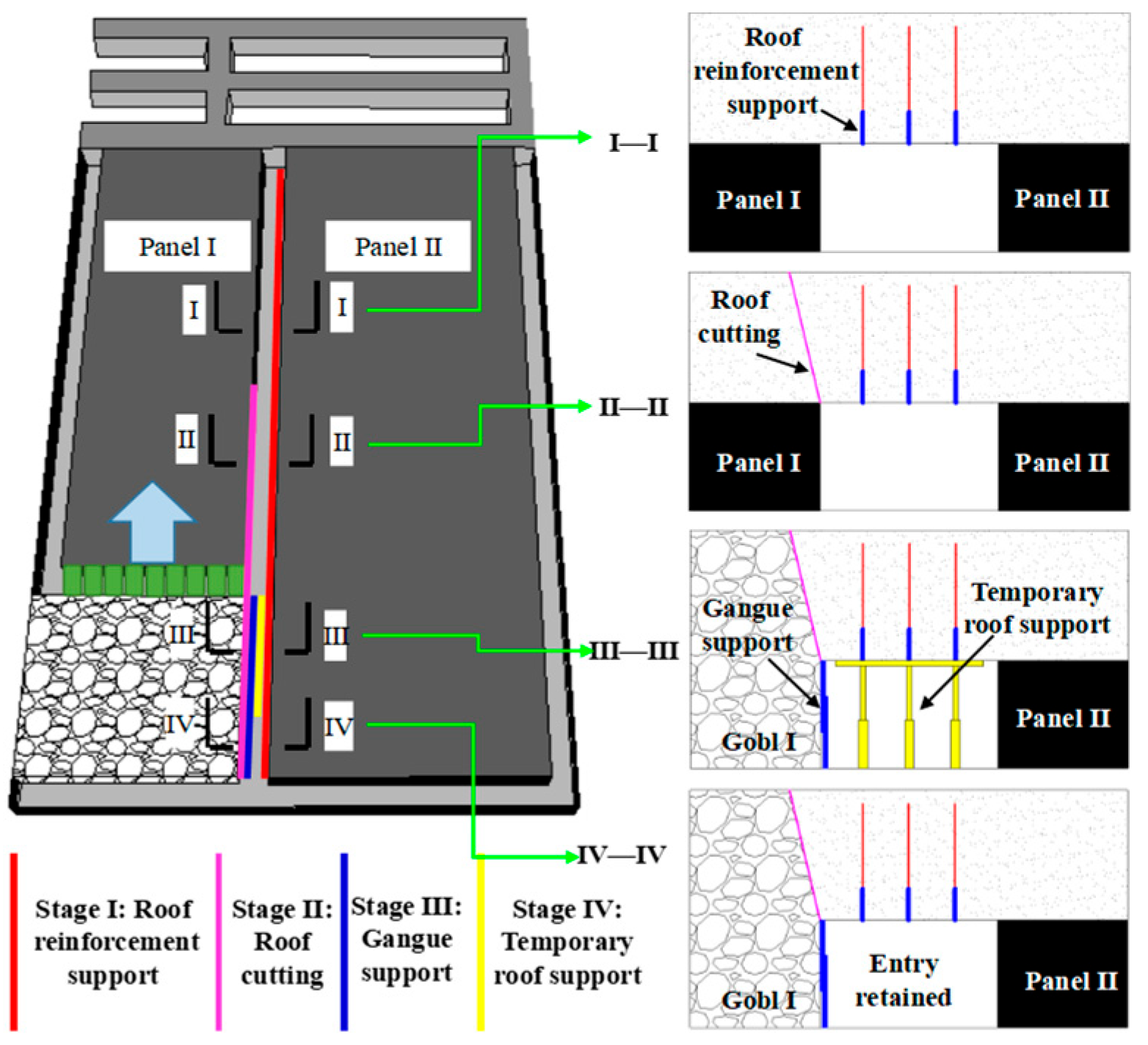
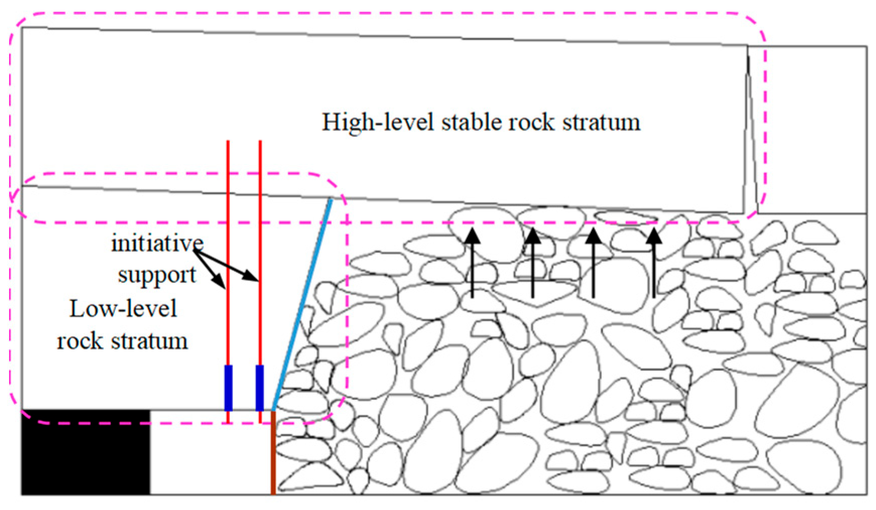
The fundamental principle of the CRRE method is illustrated in Figure 1 [27].
The CRRE technique integrates three core supporting technologies: directional roof pre-splitting cutting, roof active reinforcement support, and gangue retaining separation support. The combined application of the three technologies guarantees the stability and safety of underground mining space, improves coal resource recovery rate, and extends the service life of mines [28,29].
The CRRE process comprises four stages (Figure 1): (1) supporting—pre-mining roof reinforcement to ensure entry stability; (2) cutting—directional pre-splitting to sever the roof continuity between the entry and panel, facilitating controlled caving; (3) protecting—gangue retaining and temporary roof control during the transition phase; and (4) withdrawing—removal of temporary supports once the surrounding rock stabilizes, enabling entry reuse [30,31,32,33,34,35].
The CRRE approach has been successfully implemented in over 20 mining areas across China, spanning the Northeast, Northwest, East, North, and Southwest regions [36,37,38,39,40]. It has been applied to coal seams of various thicknesses (thin, medium, and thick) and under diverse roof conditions, including hard, fractured, and multi-composite roofs. Furthermore, this method has been extensively tested in challenging geological environments, such as high-gas and medium-deep mines. The maximum mining depth of the reported CRRE engineering case (Chengjiao Coal Mine) is only 880 m; limited scattered studies involve CRRE within 1000 m depth, while systematic research on deviatoric stress evolution and asymmetric surrounding rock failure under ultra-deep high stress (burial depth > 1000 m, σH > 60 MPa) remains insufficient [41,42].
It should be clearly emphasized that although China has 47 mines with burial depth exceeding 1000 m, systematic field tests and theoretical research of CRRE technology are rarely carried out under ultra-deep mining conditions deeper than 1000 m, and there is no evidence that all these ultra-deep mines have carried out CRRE industrial tests. Most existing engineering practices and related studies are concentrated in medium-shallow buried mines less than 1000 m. The Chengjiao Coal Mine reported in existing literature is the deepest CRRE engineering case, with a maximum burial depth of only 880 m, and its measured maximum horizontal principal stress is less than 40 MPa, which is far lower than the ultra-high in situ stress condition (σH > 60 MPa) of the ultra-deep mine in this paper (1127–1195 m burial depth). To systematically sort out the research deficiencies of existing CRRE studies and address the lack of a comparative summary of mining depth in the previous literature, we classify all published relevant literature according to burial depth and corresponding horizontal principal stress level, and form a comparative summary as follows:
(1)
Shallow mines (burial depth < 800 m, σH < 40 MPa): Zang et al. and He et al. carried out abundant field tests and numerical analyses of CRRE under low-ground-stress conditions. Their research mainly optimized roof pre-splitting parameters and conventional single support schemes, without focusing on the strong asymmetric large deformation induced by ultra-high horizontal stress in mines deeper than 1000 m. They only adopted peak abutment pressure as the single evaluation index without quantifying distortion strain energy via J2 and J3 deviatoric stress invariants.
(2)
Medium-deep mines (800 m ≤ burial depth < 1000 m): Feng et al. conducted CRRE engineering practice at the 880 m Chengjiao Coal Mine. Although they verified the basic pressure-relief effect of roof cutting, the maximum horizontal principal stress of this mine was lower than 40 MPa, far below the 60.41 MPa measured in this study. No full-cycle deviatoric stress analysis covering pre-mining advance disturbance and post-mining entry-forming stages was carried out in their work, and they did not calibrate Double-Yield gob constitutive parameters based on Salamon’s formula for high-stress environments.
(3)
Ultra-deep mines (burial depth > 1000 m): Existing related reports are limited to simple field-observation records. Few studies have established full 3D FLAC3D models to reveal the whole-process evolution law of J2 and J3, and a set of targeted differentiated surrounding rock-control technology matched for ultra-high in situ ultra-deep roadways has not been formed. International gob-side retaining technologies mainly adopt roadside filling without roof pre-splitting, which cannot effectively relieve stress under σH > 60 MPa ultra-deep conditions [43,44].
This study systematically analyzes CRRE roadways under ultra-deep conditions (1127–1195 m, σH > 60 MPa), quantifies asymmetric distortion energy via J2 and J3 invariants, and proposes a full-cycle collaborative support system.
Moreover, the Salamon gangue compaction formula adopted in most existing CRRE papers was established for medium-deep mines, and its applicability for >40 MPa high in situ stress has rarely been discussed. To fill these gaps, this study takes the 1127–1195 m working face as the object, reveals the deviatoric stress-controlled asymmetric deformation mechanism, and proposes matched full-cycle control measures based on frontier deep mining theories [45,46,47].
A number of comprehensive review papers focusing on CRRE development history and engineering application [38,46,47] have summarized nearly all domestic and international CRRE field cases, and the statistical results show that almost all test mines are buried less than 1000 m, lacking targeted mechanical response research for ultra-deep high-stress roadways. This study reveals the mechanical response of CRRE roadways under ultra-high horizontal stress (>60 MPa) at depths exceeding 1100 m. Using J2 and J3 deviatoric stress invariants, we analyze stress evolution and asymmetric deformation mechanisms in the roof and ribs, and propose targeted control measures.

2. Methods

2.1. Engineering Overview

2.1.1. Engineering Geological Conditions

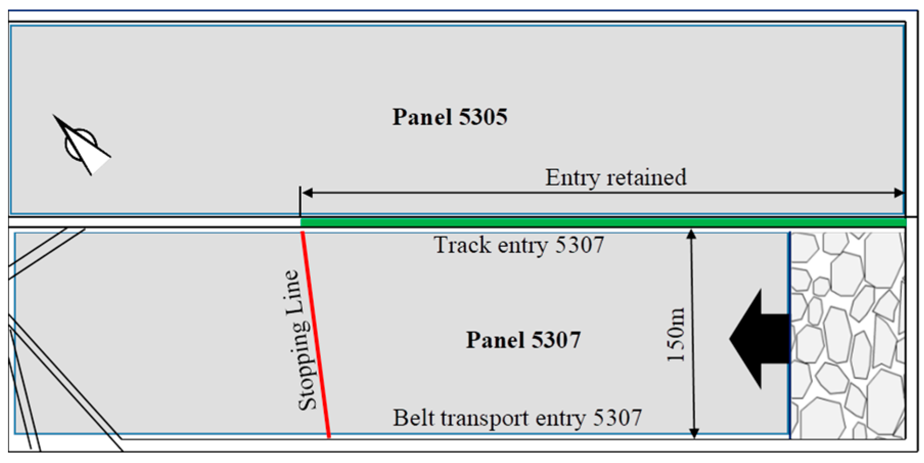
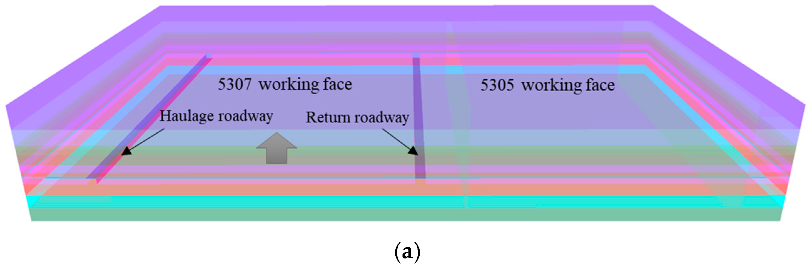
The Anju Coal Mine is situated in the central–western portion of the Jining Coalfield, within Rencheng District, Jining City, Shandong Province. Developed via vertical shafts, the mine has a designed annual production capacity of 1.5 million tons. As illustrated in Figure 2, Panel 5307 measures 480 m in length and 150 m in width, with an average coal seam thickness of 2 m. During the mining operations of Panel 5307, a 480 m segment of the 5307 track entry was retained. This retained entry will be reused for the adjacent Panel 5305, an approach that not only enhances resource recovery efficiency but also aligns with sustainable mining practices.
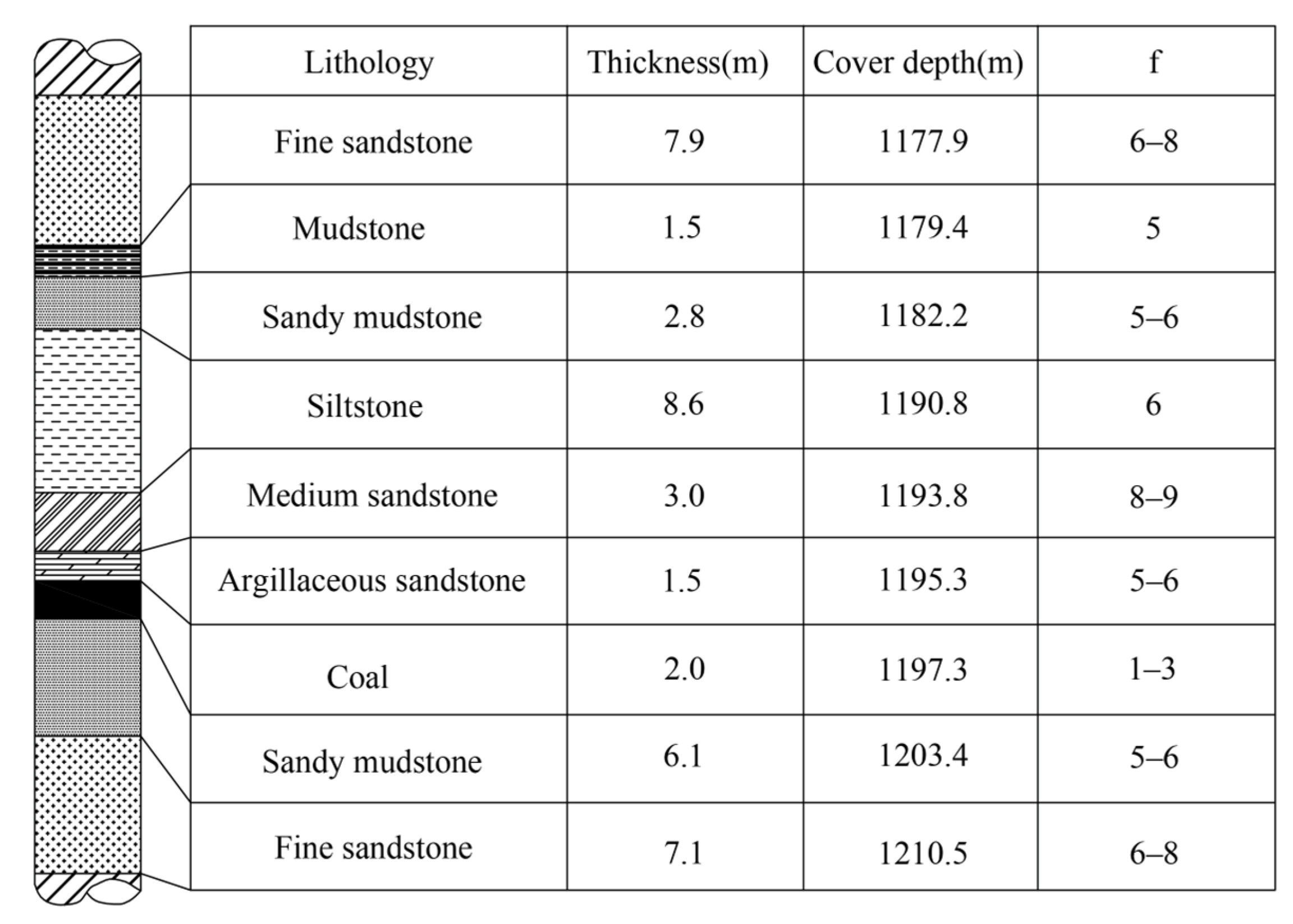
The coal seam in Panel 5307 exhibits a relatively stable and structurally simple occurrence, with burial depths ranging from 1127 to 1195 m. As illustrated in Figure 3, the immediate roof consists of fractured argillaceous sandstone with siltstone interlayers; the floor comprises gray mudstone with sandy mudstone interbeds.

2.1.2. Field In Situ Stress Measurement

Field in situ stress measurements were conducted via the hollow inclusion stress relief method at two measuring points in Anju Coal Mine, in accordance with the geological occurrence characteristics and actual production conditions of the mine. Measuring Point 1 is located 21 m to the south of the main track dip roadway of Panel 3, while Measuring Point 2 is arranged near the substation at the −1155 m horizontal level. The basic parameters of the two in situ stress measuring stations are summarized in Table 1.
Fundamental measurement data consist of strain monitoring of strain gauges arranged around the hollow inclusion during the stress relief procedure, as well as laboratory-determined elastic modulus and Poisson’s ratio of rock cores. The elastic mechanical parameters of rock cores were acquired via indoor rock mechanics tests: Measuring Point 1 has an elastic modulus of 25 GPa and a Poisson’s ratio of 0.32, while Measuring Point 2 exhibits an elastic modulus of 30 GPa and a Poisson’s ratio of 0.30. After sorting out the field-measured data and laboratory test results, a dedicated calculation program for hollow inclusion stress relief was adopted to compute the in situ stress values of Anju Coal Mine. The final calculated in situ stress results are summarized in Table 2.
An analysis of the magnitudes and orientations of all measured principal stresses yields the following conclusions:
(1)
The in situ stress field is horizontal-stress-dominated, with σH exceeding σV and lateral pressure coefficients of 1.15—1.41. Maximum horizontal stresses are 40.73 MPa (Point 1) and 60.41 MPa (Point 2), favoring roof-floor deformation.
(2)
Both measuring points indicate ESE-oriented σH. The 5307 mining entry strikes at 19° to σH, which adversely affects stability according to the maximum horizontal stress theory.

2.2. Numerical Model

2.2.1. Numerical Modeling

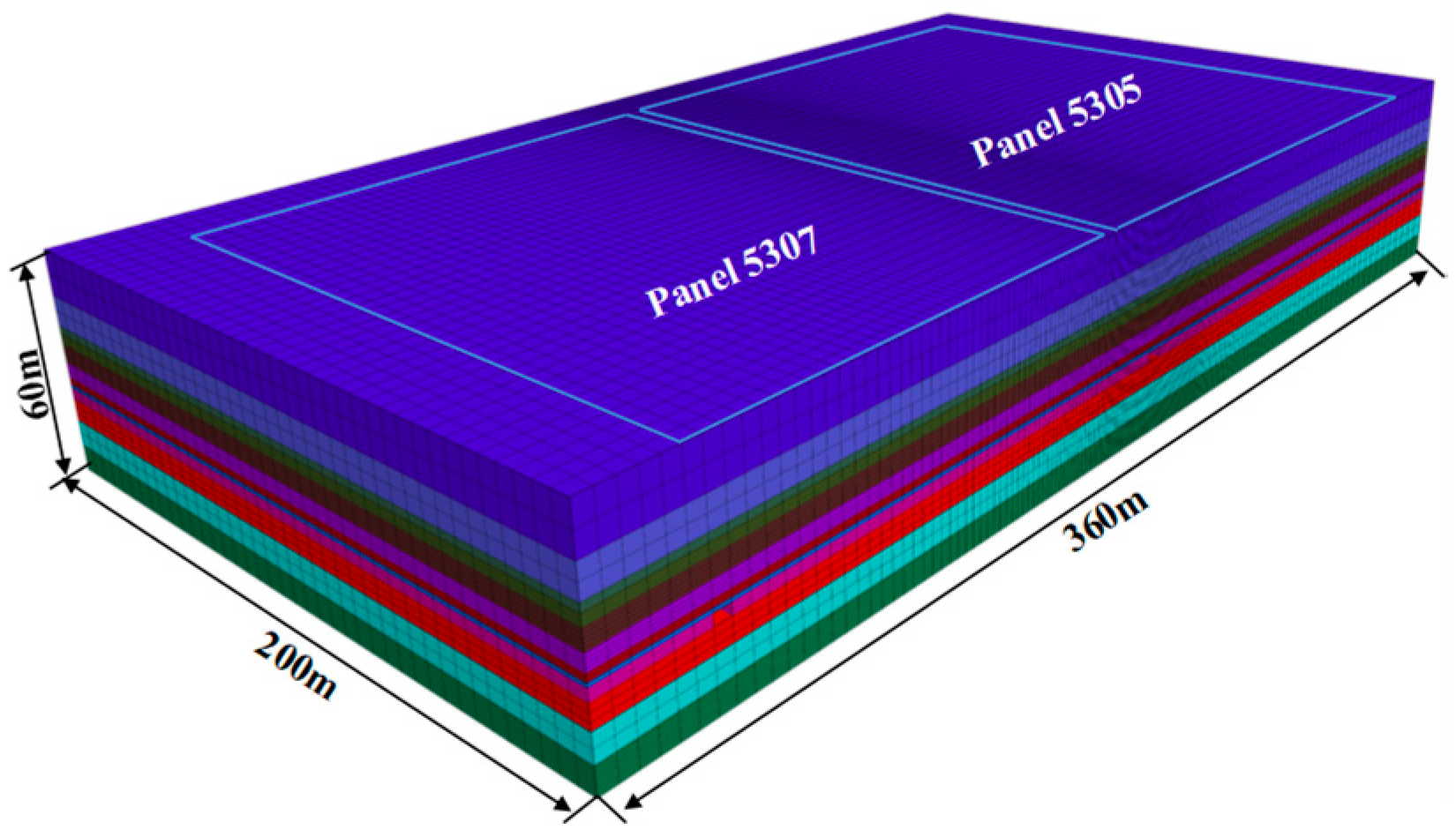
Based on the geological conditions and panel layout of the Anju Coal Mine, a three-dimensional numerical model was constructed using the FLAC3D 5.0 software, as illustrated in Figure 4. The model measures 360 m (length) × 200 m (width) × 60 m (height), covering both panels (150 m inclined length each). The physical and mechanical properties of the simulated rock strata are listed in Table 3.
All rock mechanical parameters in Table 3 are obtained from indoor uniaxial and triaxial compression tests conducted on intact rock cores drilled from the field strata of Anju Coal Mine. The laboratory rock mechanics test system conforms to the standard test specification for coal and rock mass mechanical properties.

2.2.2. Gob Modeling Method Based on the D-Y Model

The Double-Yield (D-Y) model in FLAC3D characterizes caved gob behavior via coupled shear and volumetric cap yield surfaces [48]. As specified in the FLAC3D framework, the parameters for the D-Y model comprise the cap pressure and basic matrix material properties. In the present study, the input parameters for the D-Y model were derived using Salamon’s equation, which is expressed as follows:
σ   =   E 0 ε 1     ε / ε m
where σ is the cap pressure applied to the gob materials, E0 is the initial tangential modulus of the gob material, and ε and εm are the strain and maximum strain of the gob material under applied stress, respectively. The parameters E0 and εm can be expressed using Equations (2) and (3):
ε m   =   ( b     1 ) / b
E 0   =   10.39 σ c 1.042 / b 7.7
where σc and b are the compressive strength of the rock pieces and the bulking factor of the gangue, respectively. Bulking factor b can be written as follows:
b   =   h cav   +   h m / h cav
Based on existing research findings, the height of the caving zone is typically 2 to 8 times the mining height under different geological conditions. Given that the mining height of the 5307 working face is 2.0 m, the height of its caving zone can be reasonably estimated at 8 m. Using Equation (1), the bulking factor was calculated to be 1.3. For the 5307 working face, the uniaxial compressive strength (UCS) of the overlying strata was determined as 28 MPa. This 28 MPa UCS value is the average strength acquired from indoor uniaxial compression tests of intact roof rock cores drilled at the 5307 working face of Anju Coal Mine, and this measured average value serves as the core input parameter of Salamon’s gangue compaction formula. Based on this, the initial modulus and maximum strain were calculated to be 209.22 MPa and 0.22, respectively. Table 4 summarizes the results of the cap pressures derived from Salamon’s equation.
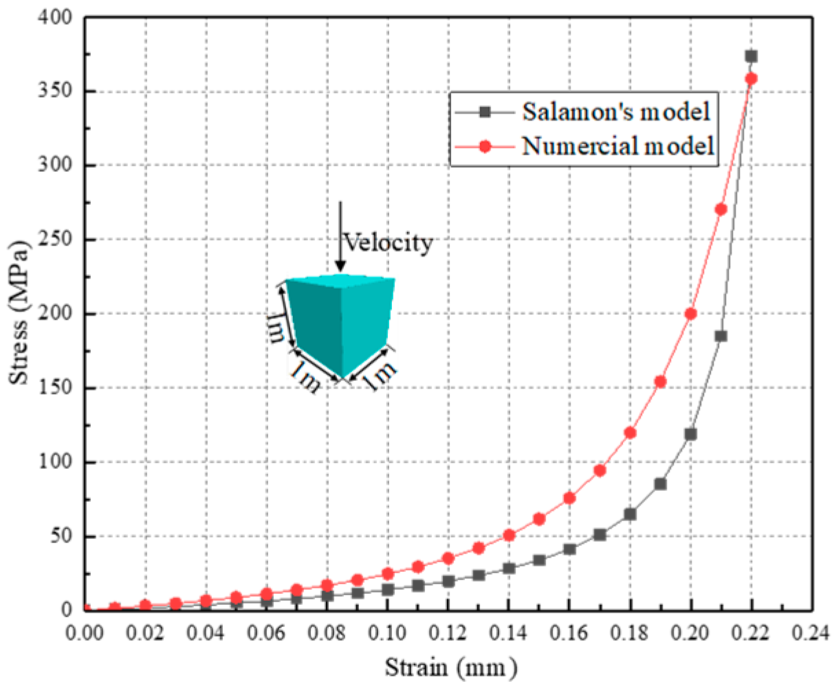
A 1 m × 1 m × 1 m sub-model was constructed to calibrate D-Y parameters against Salamon’s analytical curve. A constant loading velocity of 10−5 m/s was applied to the top surface of the sub-model, while its four lateral faces were horizontally constrained. Through a trial-and-error calibration process, the stress–strain curve generated by the numerical model was fitted against the analytical curve from Salamon’s equation. As depicted in Figure 5, the two curves exhibit a high degree of consistency. The 1 m cubic submodel only fits the intrinsic static stress–strain property of broken gangue, independent of geometric size, and its full lateral constraint replicates the confined gob compression state. The 10−5 m/s loading rate is FLAC3D standard quasi-static loading for constitutive fitting, merely used to match Salamon’s theoretical formula. The real slow long-term compaction of on-site gangue is reproduced in the large 3D stope model via step-by-step mining balance calculation, separating static parameter calibration and dynamic field strata movement. The resulting optimized parameters for the D-Y model are summarized in Table 5.
The mechanical parameters of the Double-Yield gob model listed in Table 5 are calibrated based on Salamon’s gangue compaction formula and indoor confined compression test results of broken rock samples from Anju Coal Mine. The previous typographical errors on unit and decimal points of bulk modulus, shear modulus, and density have been corrected to conform to the physical properties of caved gangue.

2.2.3. Verification of the D-Y Model for Gob Material

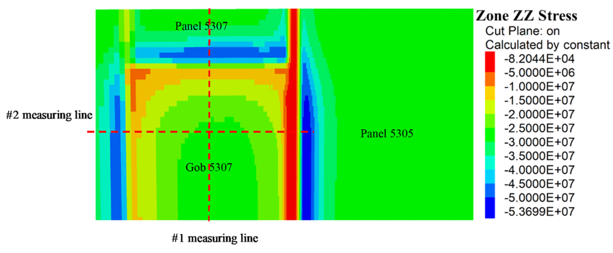
To further validate the stress recovery characteristics and parameter reliability of the D-Y model, a numerical simulation was conducted for a 150 m advance at the 5307 working face. The vertical stress distribution within the gob is illustrated in Figure 6. The D-Y model successfully reproduces gob bulking and load-bearing behavior. Specifically, the vertical stress gradually increases from the gob edge toward its interior, indicating the progressive restoration of the bearing capacity of the caved gangue in accordance with the Double-Yield constitutive theory [49].
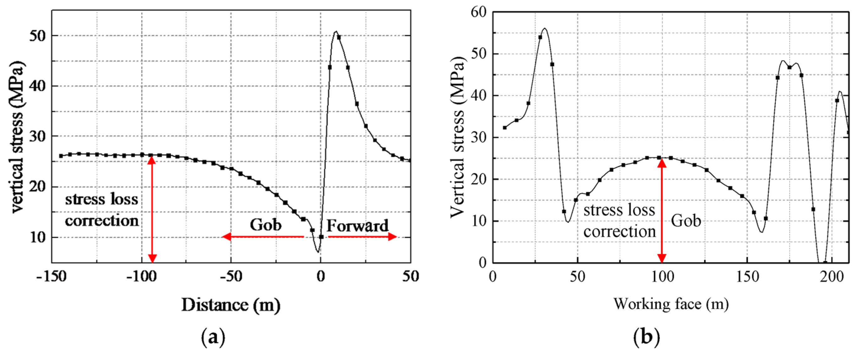
Figure 7 presents the stress distribution curves based on the measuring lines within the gob. Measuring Line 1 extends along the strike direction at the mid-section of the working face; the vertical stress in the gob reaches 26.3 MPa at 90 m behind the working face, recovering to 95% of the initial in situ stress (27.5 MPa). This 90 m lag distance with 95% in situ stress recovery falls entirely within the measured range (80–100 m, 90–98% stress recovery) of existing field-monitoring cases of >1000 m-deep fully mechanized faces, preliminarily verifying the D-Y parameter rationality from engineering universality. Measuring Line 2 is laid out along the dip direction, 40 m behind the working face. The stress increases gradually from the retained entry toward the central gob, with the vertical stress at the dip midpoint reaching 25.1 MPa, which is equivalent to 91% of the in situ stress (27.5 MPa). In conclusion, the calibrated parameters of the D-Y model are well validated, proving its capability to accurately reproduce the compaction and stress recovery behavior of caved gangue. Complete field ground pressure monitoring data, including hydraulic support working resistance and solid coal rib abutment pressure, are unavailable for the investigated working panel due to limitations in the underground monitoring system and field construction conditions. Accordingly, the present study primarily focuses on revealing the mechanical evolution mechanism of compacted caving gangue behind the working face, rather than conducting accurate quantitative prediction of field ground pressure responses. The mechanical parameters adopted in the D-Y model have been fully calibrated through indoor uniaxial compression submodel tests to ensure parameter rationality. The stress recovery trend of gangue shown in Figure 7—specifically, the stress recovering to 95% of its initial value at a distance of 90 m from the working face—is consistent with the universal strata behavior characteristics of deep fully mechanized mining faces reported in the existing literature. To further validate the model, we cross-compare simulation displacement distribution with the field roadway deformation data in Section 3.3. The asymmetric roof subsidence/floor heave distribution and 250 m stabilization lag distance from simulation perfectly match field-measured deformation laws, indirectly proving the model can reflect the mine’s ground pressure evolution. Complete hydraulic support resistance and solid coal rib pressure data are unavailable due to underground monitoring system and construction limitations at Anju Coal Mine, so direct quantitative stope stress comparison cannot be implemented. This consistency demonstrates that the established numerical model is capable of reflecting the essential ground pressure evolution law of the target coal mine from a mechanical mechanism perspective.

2.2.4. Uncertainty Analysis and Limitations of the Established Numerical Model

Although the Double-Yield constitutive parameters of caved gangue and rock mass mechanical properties are calibrated via Salamon’s compaction formula and laboratory rock mechanics tests, the numerical predictions inevitably contain uncertainties originating from material parameter selection and modeling simplifications, which are discussed as follows.
(1)
Uncertainty induced by rock mass material properties. The mechanical parameters of roof, floor, and coal strata used in the model are derived from uniaxial and triaxial compression tests of intact rock cores, which cannot fully reflect the mechanical deterioration of fractured in situ rock masses containing joints and microcracks. The actual strength and deformation modulus of the field rock mass are generally lower than laboratory test values, which may slightly overestimate the bearing capacity of surrounding rock and underestimate the asymmetric deformation magnitude of the retained entry.
(2)
Uncertainty from the Double-Yield gob constitutive assumption. The Salamon gangue compaction formula adopted to calibrate cap pressure parameters is summarized from medium-deep mining cases. In this ultra-deep mine with horizontal in situ stress exceeding 60 MPa, the dilatancy and compaction characteristics of broken gangue under ultra-high confining pressure may deviate from the theoretical formula. The bulking factor b = 1.3 used in this study is an empirical average value; variations in gangue fragmentation degree change the stress–strain response of the gob, further affecting the stress transfer law of overlying strata.
(3)
Simplified modeling assumptions bring inevitable errors. To balance calculation efficiency and model scale, the 3D numerical model simplifies complex geological conditions: small-scale faults and local fracture zones are not reconstructed, and the coupling effect of high geothermal temperature and pore water pressure in ultra-deep strata is ignored. Meanwhile, the NPR anchor cable and temporary support are simplified as equivalent structural elements instead of fully refined discrete components, which may smooth local stress concentrations near support components.
(4)
Limitations of the present numerical model. This study only conducts quasi-static step-by-step mining calculation without introducing creep constitutive models, so the long-term slow deformation of surrounding rock after roadway stabilization cannot be quantitatively reproduced. In addition, limited by field-monitoring conditions, complete measured data of hydraulic support working resistance and solid coal rib abutment pressure are unavailable to achieve full quantitative calibration of the model; only roadway surface displacement and gob stress recovery characteristics are used for indirect verification.
Despite the above uncertainties and limitations, the numerical model still reliably reveals the evolution law of deviatoric stress invariants J2, J3, and asymmetric deformation characteristics under ultra-deep high-stress conditions. The overall variation trend of simulation results matches the 480 m field-monitoring data well (deviation less than 10%), which proves that the proposed differentiated collaborative control technology is robust for similar ultra-deep gob-side entry retaining engineering. Subsequent research will further optimize the model by introducing creep parameters and refined fault geological modeling to reduce prediction uncertainty.

2.3. Comparison Scheme for Numerical Simulation Experiments

FLAC3D was employed to perform numerical simulation experiments on two mining schemes: pillarless gob-side entry retaining by roof cutting and conventional mining with coal pillar retention. The distribution characteristics of mining-induced abutment pressures under both methods were analyzed, focusing on the strike stress distribution along the working face, the dip stress distribution ahead of the mining front, and the dip stress characteristics behind the working face.
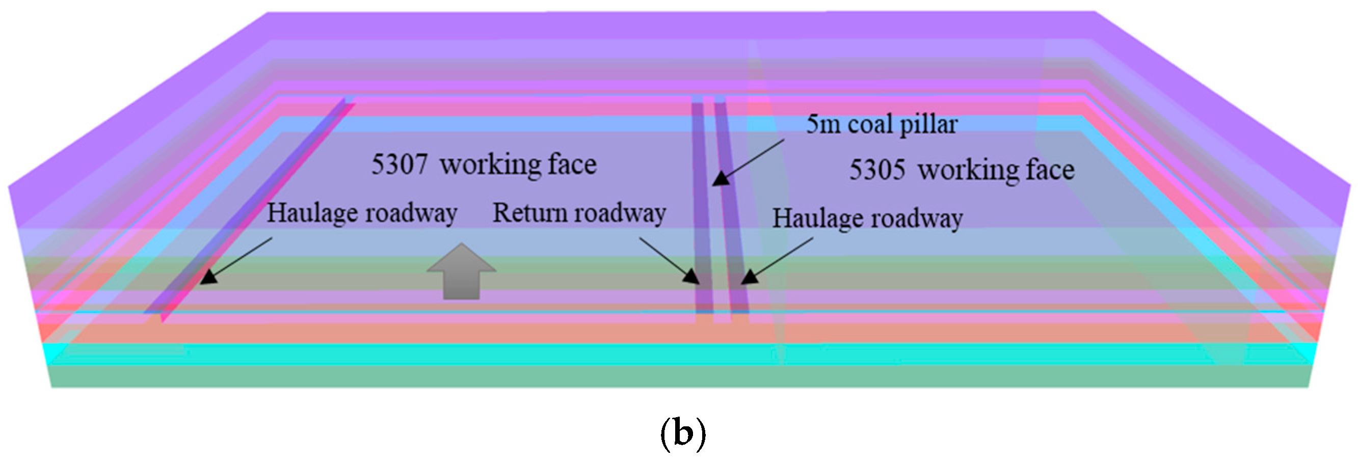
For the pillarless roof-cutting scheme, a two-roadway layout was implemented, wherein the 5307 track entry was retained to serve the adjacent 5305 working face. This face featured a dip length of 150 m and a roof cutting height of 7 m. In contrast, the pillar-retaining scheme utilized a three-roadway layout incorporating an additional belt entry for the 5305 working face, while maintaining the same 150 m dip length. In alignment with the engineering practices at the Anju Coal Mine, a 5 m-wide coal pillar was reserved. The comparative experimental setups for the two mining methods are illustrated in Figure 8. Both models simulated a panel advance of 100 m, with the D-Y model applied to simulate the gob behavior. To eliminate errors from mesh discretization and iterative convergence, both mining models were run three times with minor mesh adjustments. For all key stress indices, mean values and standard deviations (SD) were calculated. Bootstrap resampling (1000 samples, 95% confidence interval) and independent t-tests were used to test statistical significance; p < 0.05 indicates a significant difference between the two mining schemes. Error bars in all stress plots correspond to the SD of three repeated simulations.

3. Results and Discussion

3.1. Analysis of Numerical Simulation Experiments

3.1.1. Distribution and Evolution Law of Mining-Induced Stress Along the Working Face Strike

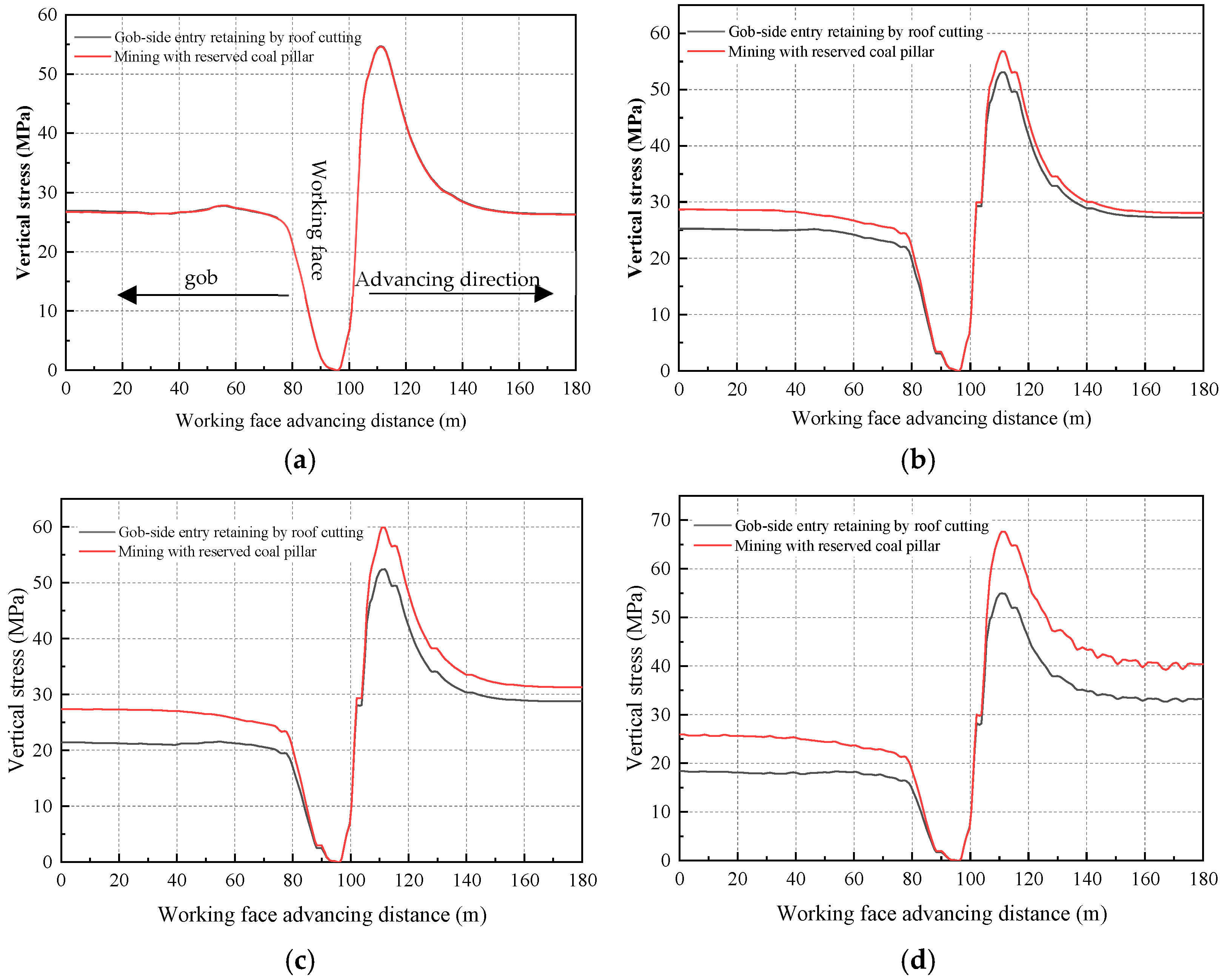
To comparatively analyze the distribution characteristics of mining-induced abutment pressure along the working face strike under both schemes, four vertical stress-monitoring lines were arranged at the coal seam floor. These lines were positioned at distances of 75 m (the mid-section of the working face), 30 m, 20 m, and 10 m from the 5307 track entry. The vertical stress distributions along the working face strike obtained from the numerical simulations are illustrated in Figure 9.
(1)
At the 75 m midsection line, mean peak stresses are nearly identical (p = 0.87), reaching 54.6 MPa (SCF = 1.99), excluding mesh bias. However, as the distance to the 5307 track entry decreases, the profiles diverge significantly: at 30 m, the peak pressure is 53.1 MPa (SCF: 1.93) for the pillarless scheme versus 56.8 MPa (SCF: 2.07) for the pillar-retaining scheme. At 20 m, it is 52.3 MPa (SCF: 1.90) for the pillarless scheme compared to 59.9 MPa (SCF: 2.18) for the pillar-retaining scheme. At 10 m, it reaches 54.9 MPa (SCF: 2.00) for the pillarless scheme, whereas it escalates to 67.7 MPa (SCF: 2.46) for the pillar-retaining scheme.
(2)
From the panel mid-section toward the 5307 track entry, the advanced abutment pressure under the pillarless roof-cutting scheme exhibits a decrease-then-increase trend. The SCF drops from 1.99 at the mid-section to a minimum of 1.90 at the 20 m mark, before rebounding to 2.00 at the 10 m mark. In contrast, the pressure under the conventional pillar-retaining scheme increases continuously, with the SCF rising monotonically from 1.99 to 2.46. This divergent behavior demonstrates that the coal pillar left between Panels 5307 and 5305 acts as a major load-bearing element, where severe stress concentration significantly intensifies the advanced abutment pressure on the adjacent working face.
(3)
Moving from the panel mid-section toward the 10 m mark near the 5307 track entry, the advanced abutment pressure differential between the two methods expands from 0 to 12.8 MPa. Thus, stress reduction by the pillarless roof-cutting approach intensifies closer to the entry.

3.1.2. Distribution and Evolution Law of Mining-Induced Stress Along the Dip Direction of the Working Face

Distribution of Mining-Induced Abutment Pressure Along the Dip Direction in Front of the Working Face
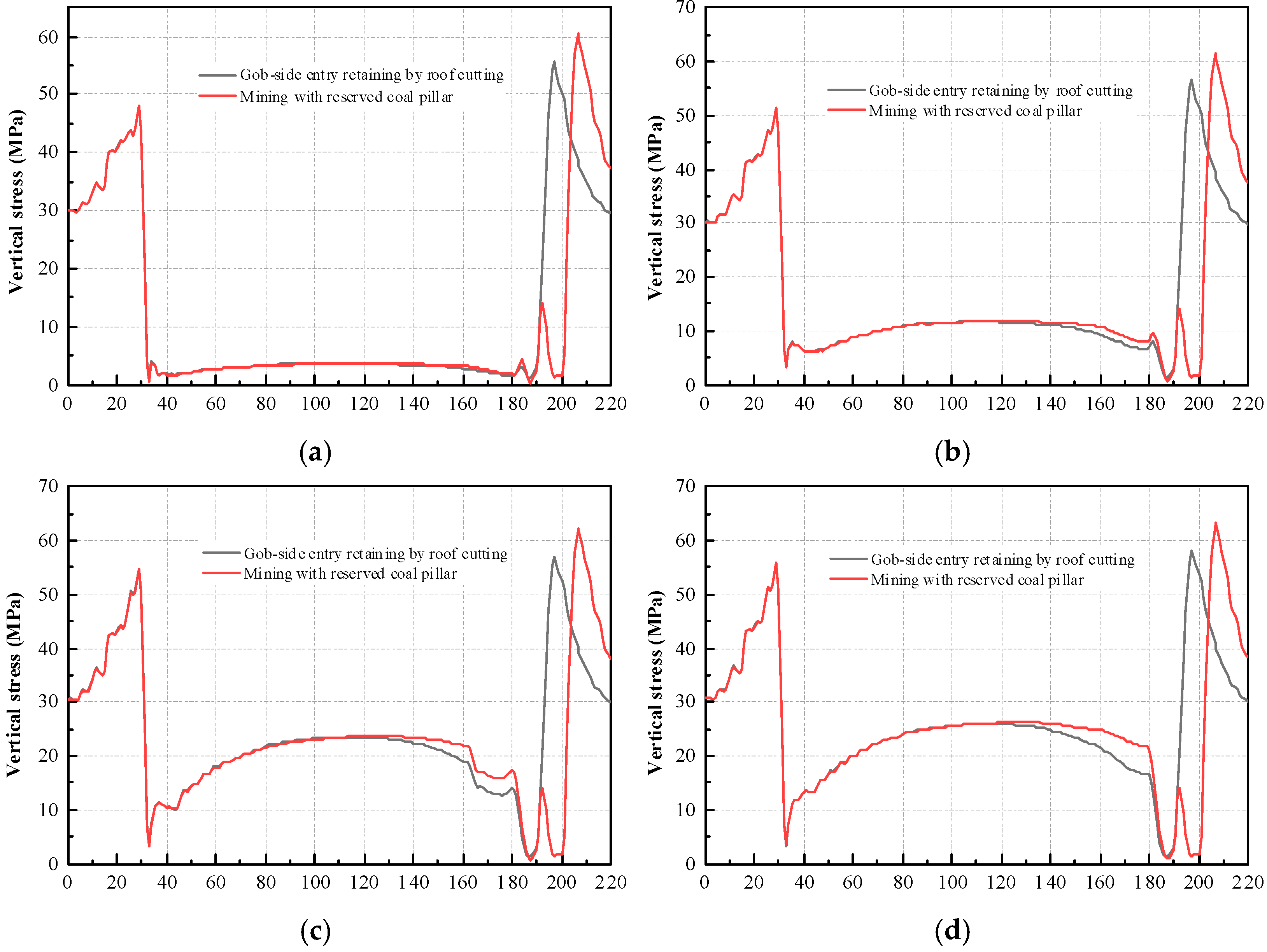
To comparatively analyze the distribution characteristics of mining-induced abutment pressure along the dip direction ahead of the working face under both schemes, four stress-monitoring lines were arranged at the coal seam floor. These lines were positioned at distances of 10 m, 20 m, 30 m, and 40 m ahead of the working face. The dip-direction vertical stress distributions obtained from the numerical simulations are illustrated in Figure 10.
As illustrated in Figure 10,
(1)
Along the panel dip direction, stress concentration occurs near the mining entry under both the pillarless roof-cutting and pillar-retaining schemes, with the abutment pressure increasing markedly under the influence of mining disturbances. For both methods, the active mining side is profoundly affected by the mining-induced advanced abutment pressure. Under the pillarless roof-cutting scheme, the vertical stress on the active mining side exceeds that on the non-mining side. Similarly, for the pillar-retaining scheme, the stress on the 5307 working face is higher than that on the 5305 working face. Because the solid coal mass on both sides sustains the bulk of the abutment load, the narrow coal pillar exhibits localized stress concentration but carries a lower absolute vertical stress profile due to yielding.
(2)
On the active mining side (5307 working face), the peak stresses for the pillar-retaining scheme at 10 m, 20 m, 30 m, and 40 m ahead of the working face are 69.2, 59.1, 50.5, and 47.6 MPa, respectively. In comparison, the corresponding peak stresses for the pillarless roof-cutting scheme drop to 56.4, 46.2, 40.7, and 37.9 MPa, representing substantial stress reductions of 18%, 22%, 19%, and 20%, respectively.
(3)
Synthesizing the insights from Figure 9 and Figure 10, the peak advanced abutment pressure consistently occurs approximately 10 m ahead of the mining front. Beyond this 10 m threshold, the abutment pressure diminishes progressively as the distance from the working face increases.
The 18–22% average stress relief rate is statistically averaged from peak abutment pressures measured 10–40 m ahead of the working face. The destressing effect weakens gradually as the advance distance increases: the maximum stress reduction reaches 22% at 10 m ahead of the working face, while the reduction drops to 18% at 40 m ahead. For positions over 40 m in advance, mining disturbance fades, and the stress difference between the roof-cutting entry-retaining scheme and the coal pillar scheme is less than 10%, meaning the 18–22% stress reduction range is only valid within the 10–40 m advance disturbance zone rather than all distances.
Distribution of Mining-Induced Abutment Pressure Along the Dip Direction Behind the Working Face
To comparatively investigate the distribution of lagging mining-induced abutment pressures along the panel dip direction under both schemes, four vertical stress-monitoring lines were installed at the coal seam floor. These lines were situated at distances of 5 m, 10 m, 15 m, and 20 m behind the working face. The resulting dip-direction lagging abutment pressure distributions are illustrated in Figure 11.
As illustrated in Figure 11,
(1)
Along the panel dip direction, the caved roof material in the center of the gob undergoes progressive collapse and compaction under both mining methods, initiating an early recovery of vertical stress in this zone. Specifically, at 5 m behind the working face, the vertical stress at the gob center is 3.63 MPa, which recovers significantly to 25.9 MPa at a distance of 20 m. Throughout this gob compaction process, the stress within the surrounding rock of the retained entry increases gradually before eventually stabilizing.
(2)
The peak stress at the gob edge under the pillarless roof-cutting scheme is consistently lower than that under the pillar-retaining scheme. For the pillarless scheme, the edge stress recovers from 3.0 MPa at 5 m behind the mining front to 13.0 MPa at 20 m. In contrast, for the pillar-retaining scheme, the peak edge stress increases from 4.2 MPa at 5 m to 16.7 MPa at 20 m.
(3)
Similarly, the peak stress on the solid coal rib side is noticeably reduced under the pillarless roof-cutting scheme compared to the conventional pillar-retaining alternative. At 5 m behind the working face, the peak stress on the solid coal rib for the pillarless scheme is 55.6 MPa, whereas that along the 5305 belt entry under the pillar-retaining scheme is 59.6 MPa, representing a 6.7% reduction. At 20 m behind the working face, the peak stress on the solid coal rib is 58.0 MPa for the pillarless scheme versus 63.1 MPa for the pillar-retaining scheme, marking an 8.0% stress reduction.

3.1.3. Characteristics of Deviatoric Stress Invariants and Displacement Distribution in the Advanced Mining Stage

J2 quantifies deviatoric distortion energy (higher J2 indicates greater shear/bending failure risk), while J3 distinguishes compressive (negative) from tensile (positive) strain regimes [50]. Their combined distribution characterizes asymmetric deformation in ultra-deep roadways under high horizontal stress. During the pillarless mining process with roof cutting for gob-side entry retaining, the surrounding rock of the retained entry is subjected to two distinct, major disturbances. First, the advanced abutment pressure induced by working face extraction inflicts structural damage on the coal-rock mass ahead of the 5307 track entry. Second, following face advancement, the overlying strata movement during gob compaction causes secondary damage to the surrounding rock of the 5307 track entry. This dual-damage mechanism within the surrounding rock of the retained entry is effectively reflected by variations in the deviatoric stress field.
To investigate the influence of face advancement on the stability of the surrounding rock ahead of the mining front, a 100 m advance at the 5307 working face was simulated. The distribution characteristics of the second and third invariants of the surrounding rock deviatoric stress, monitored 10 m ahead of the 5307 track entry relative to the working face, were systematically analyzed.
Distribution Characteristics of the Second Invariant of Deviatoric Stress
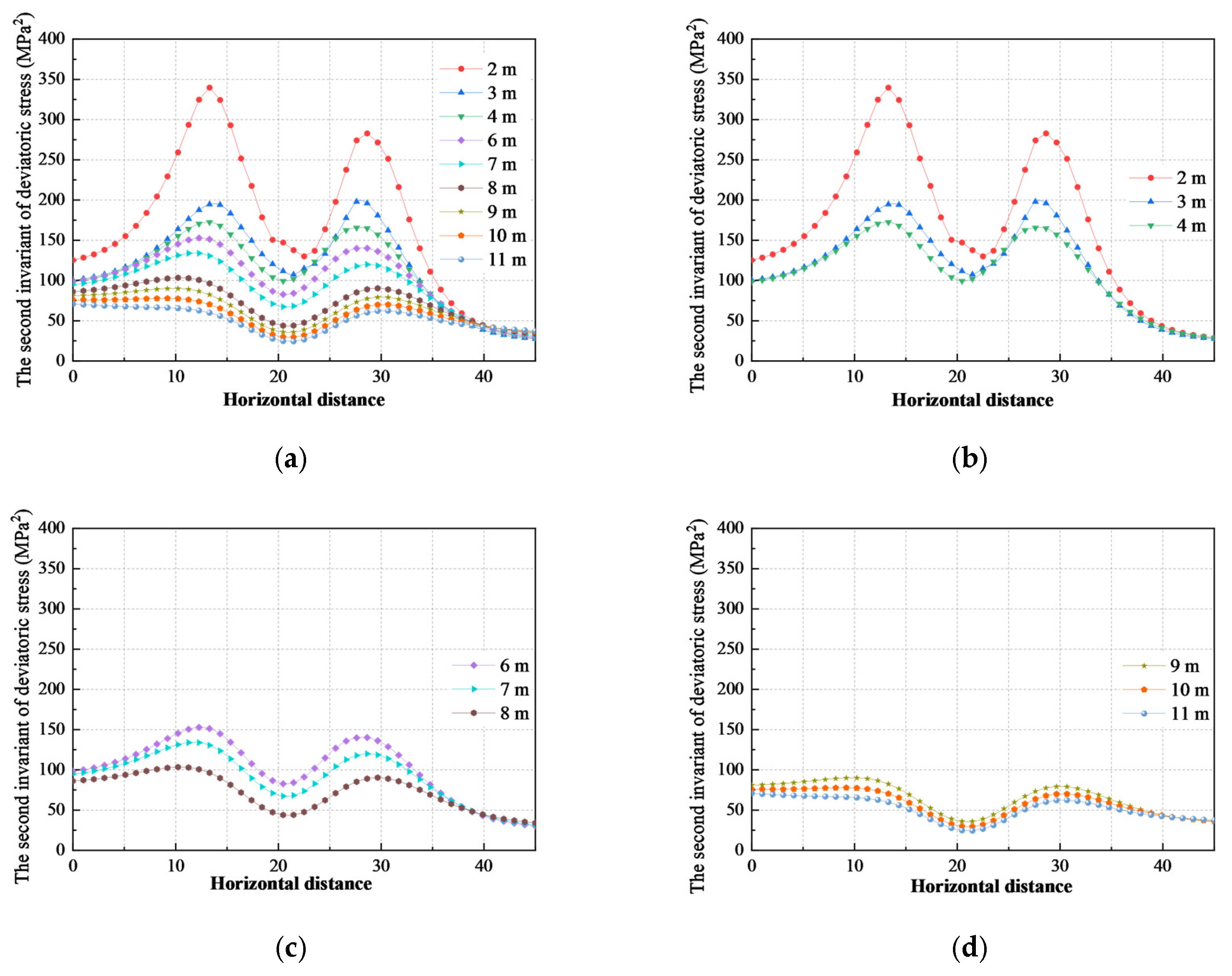
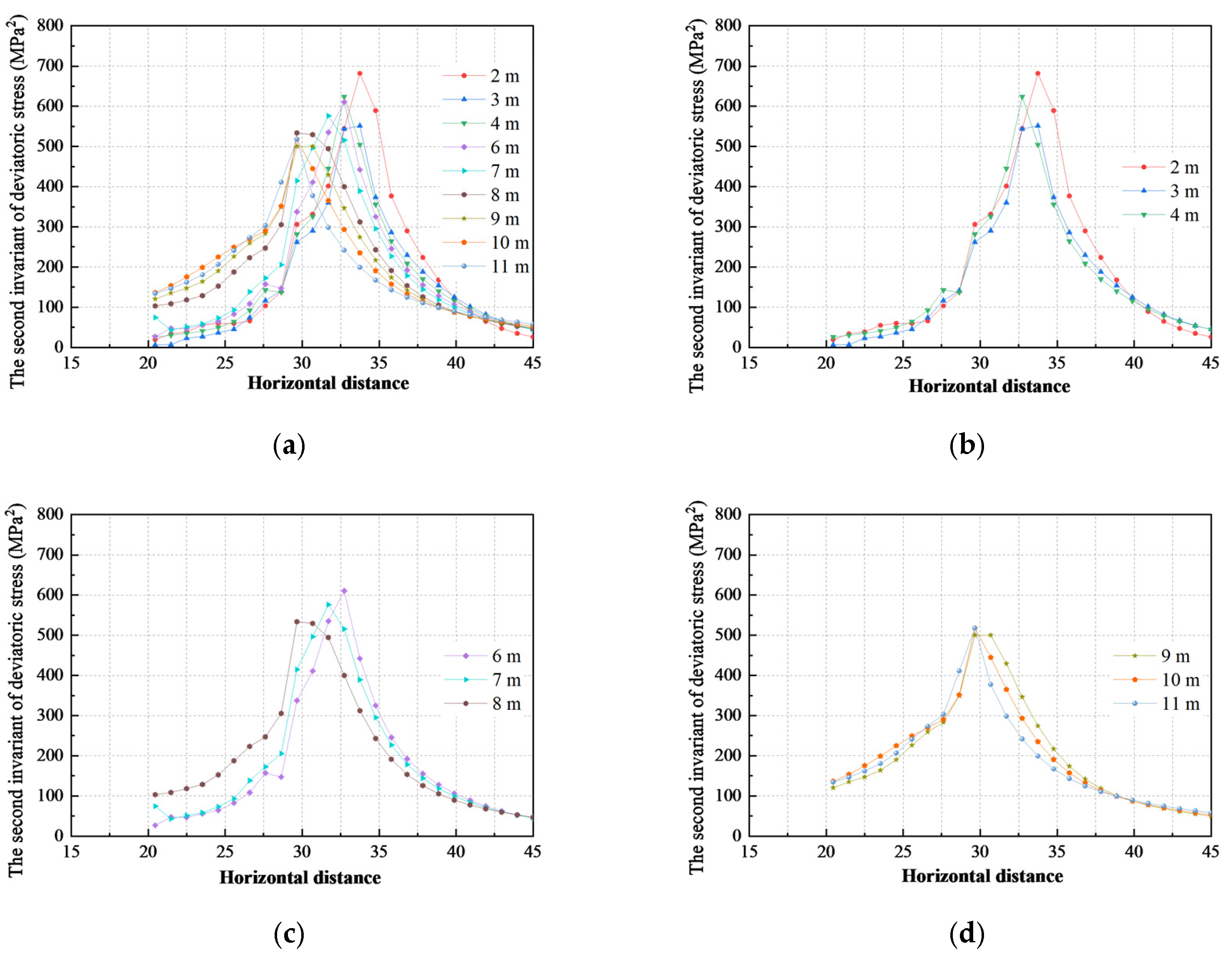
The distribution of the second invariant (J2) of deviatoric stress within various roof strata horizons of the 5307 track entry (the gob-side entry formed by roof cutting) under the influence of advanced mining abutment pressure is illustrated in Figure 12.
As illustrated in Figure 12,
(1)
J2 exhibits a saddle-shaped distribution horizontally: minima in the deep working face and above the gateway, with concentration (high distortion energy) in adjacent roof strata. In addition, the value of the second invariant of the 5307 working face is greater than that of the 5305 working face, indicating that working face mining has a greater impact on the current working face, and the distortion energy stored in the overlying strata of the 5307 working face is larger than that of the 5305 working face. For the overlying strata of the solid coal on both sides of the gob-side entry formed by roof cutting, the peak value of the second invariant of deviatoric stress on the mining side is 5~10 m away from the gateway rib, and that on the non-mining side is less than 5 m away from the gateway rib. Although the distortion energy on the mining side is large, the non-mining side is closer to the gateway roof. Therefore, the overlying strata within the influence range of advanced abutment pressure will all affect the stability of the gateway roof.
(2)
The distribution of the second invariant in the overlying strata of the gateway shows obvious asymmetry. The second invariant of the roof near the non-mining side is greater than that near the mining side, and the distortion energy of the roof near the mining side is smaller, indicating that directional pre-splitting blasting of the roof reduces the distortion energy of the roof on the mining side.
(3)
The deviatoric stress of strata at different heights above the roof varies, and generally, the second invariant of deviatoric stress in the roof strata decreases with the increase in height. The peak value of the second invariant of deviatoric stress in the low-position roof strata decreases from 335 MPa2 at 2 m above the roof to 172.4 MPa2 at 4 m above; that in the middle-position roof strata decreases from 152.8 MPa2 at 6 m above to 103.4 MPa2 at 8 m above; and that in the high-position roof strata decreases from 89.9 MPa2 at 9 m above to 66.8 MPa2 at 11 m above. The reduction amplitudes of the three types of strata are 162.6 MPa2, 49.4 MPa2, and 23.1 MPa2, respectively, indicating that the reduction amplitude of the second invariant decreases with the increase in strata height. The high-position roof has small distortion energy and good stability, while the low-position roof strata have a large second invariant, indicating that the low-position roof strata are relatively more prone to deformation and damage. Therefore, in the roof control of gob-side entry formed by roof cutting, effective support measures should be adopted to strengthen the mechanical connection between the low-position roof strata and the high-position stable roof strata. In this study, the term “bending failure” refers to the tensile fracture and separation of layered roof strata induced by uneven subsidence and rotational deformation of the short cantilever beam above the retained entry. The high value of deviatoric stress invariant J2 reflects the accumulated distortion strain energy within rock layers; a concentrated high-J2 zone demonstrates severe bending deformation potential. Combined with asymmetric vertical displacement cloud maps showing uneven roof subsidence between the gob side and solid-coal side, the coexistence of elevated J2 and differential displacement directly proves the generation and development of roof bending failure.
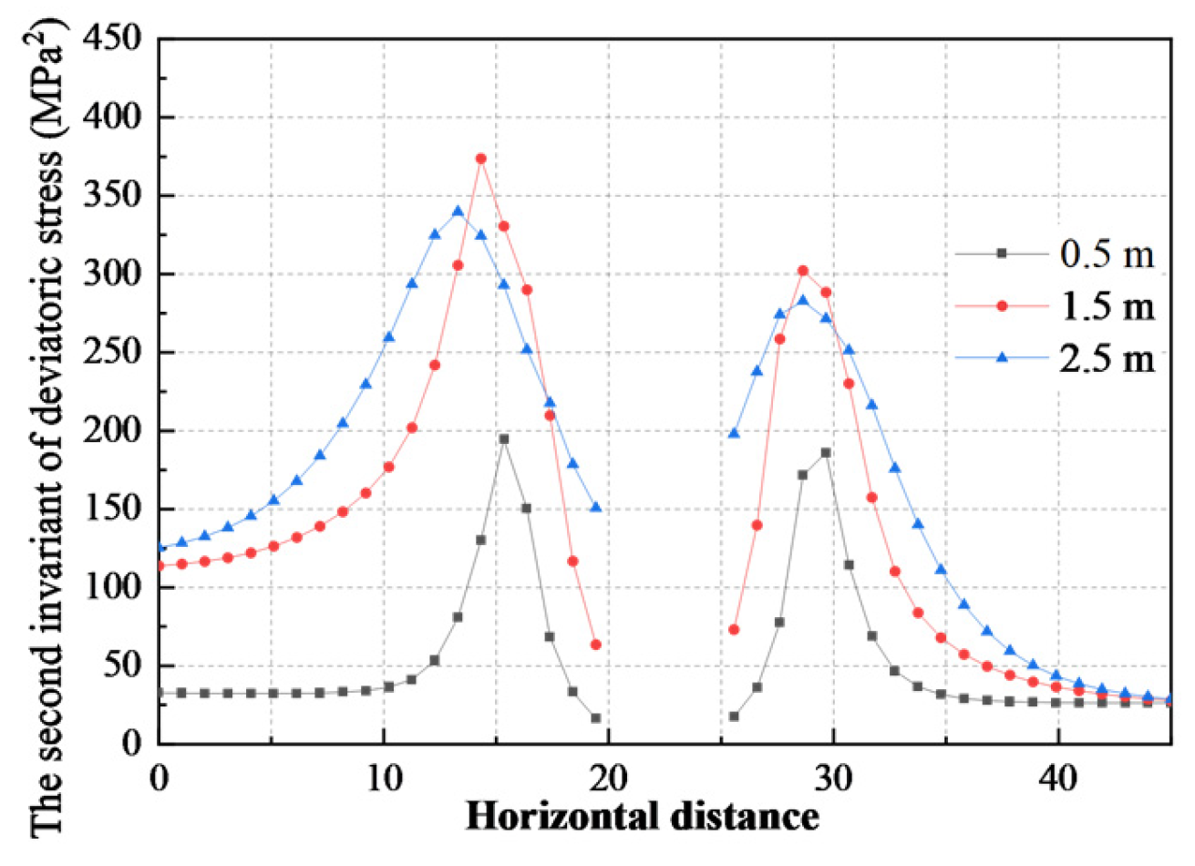
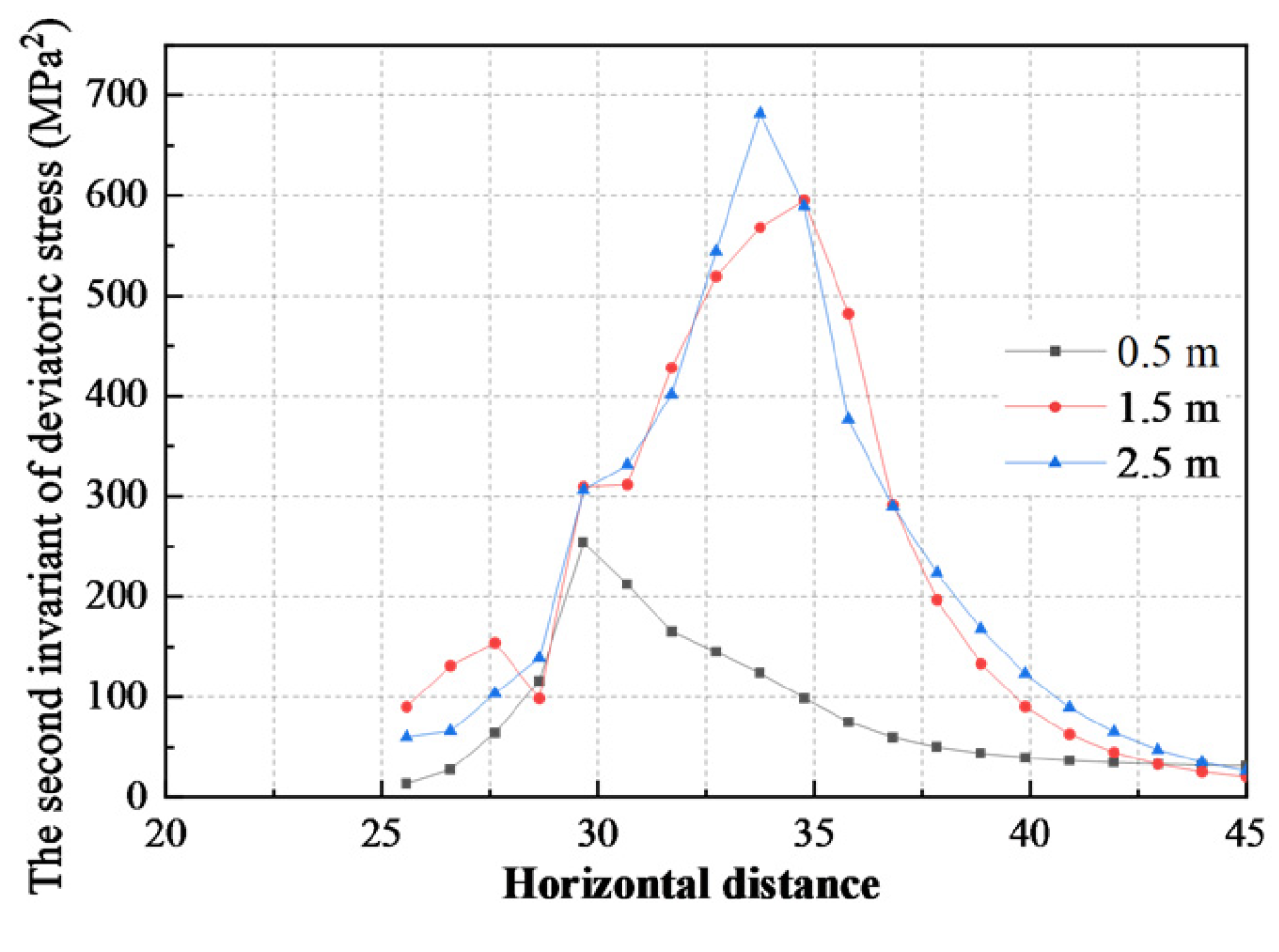
Both sides of the advanced area of the gob-side entry formed by roof cutting are solid coal, and the distribution of the second invariant J2 of deviatoric stress on both sides of the 5307 working face track gateway under the influence of mining abutment pressure is shown in Figure 13.
As illustrated in Figure 13,
(1)
Moving from the entry rib into the deep solid coal mass, the second invariant of deviatoric stress (J2) initially increases before decreasing. On the mining side, the peak J2 value is located 5–8 m deep within the coal mass, with an intensity exceeding 350 MPa2. On the non-mining side, the peak occurs 4–5 m deep within the coal, reaching approximately 300 MPa2. Under the influence of advanced abutment pressure, the mining side accumulates greater distortion energy, which macroscopically manifests as more pronounced rib bulging within a specific zone ahead of the working face compared to the non-mining side.
(2)
The peak J2 values vary distinctly at different heights along both entry ribs, adhering to the following hierarchical order: the middle of the entry rib (1.5 m) > the near-roof area (2.5 m) > the near-floor area (0.5 m). The peak J2 value at the mid-height of the entry rib is the largest, corresponding to elevated distortion energy storage. This indicates that the mid-section of the entry rib is relatively more vulnerable to deformation and failure.
Distribution Characteristics of the Third Invariant of Deviatoric Stress
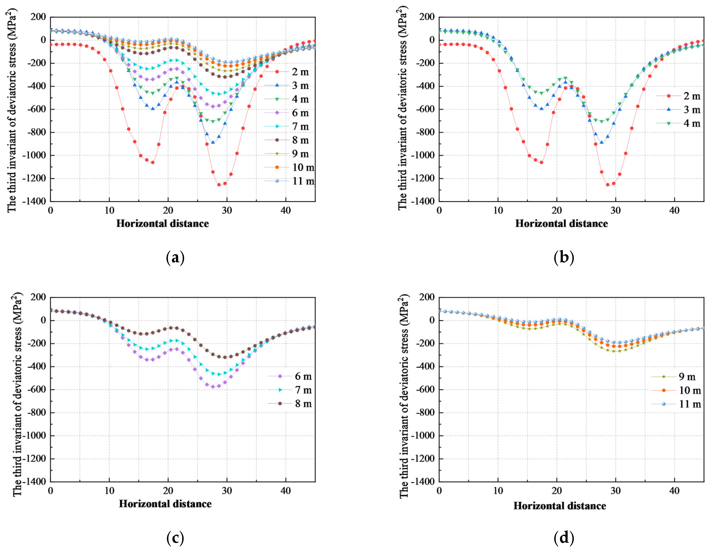
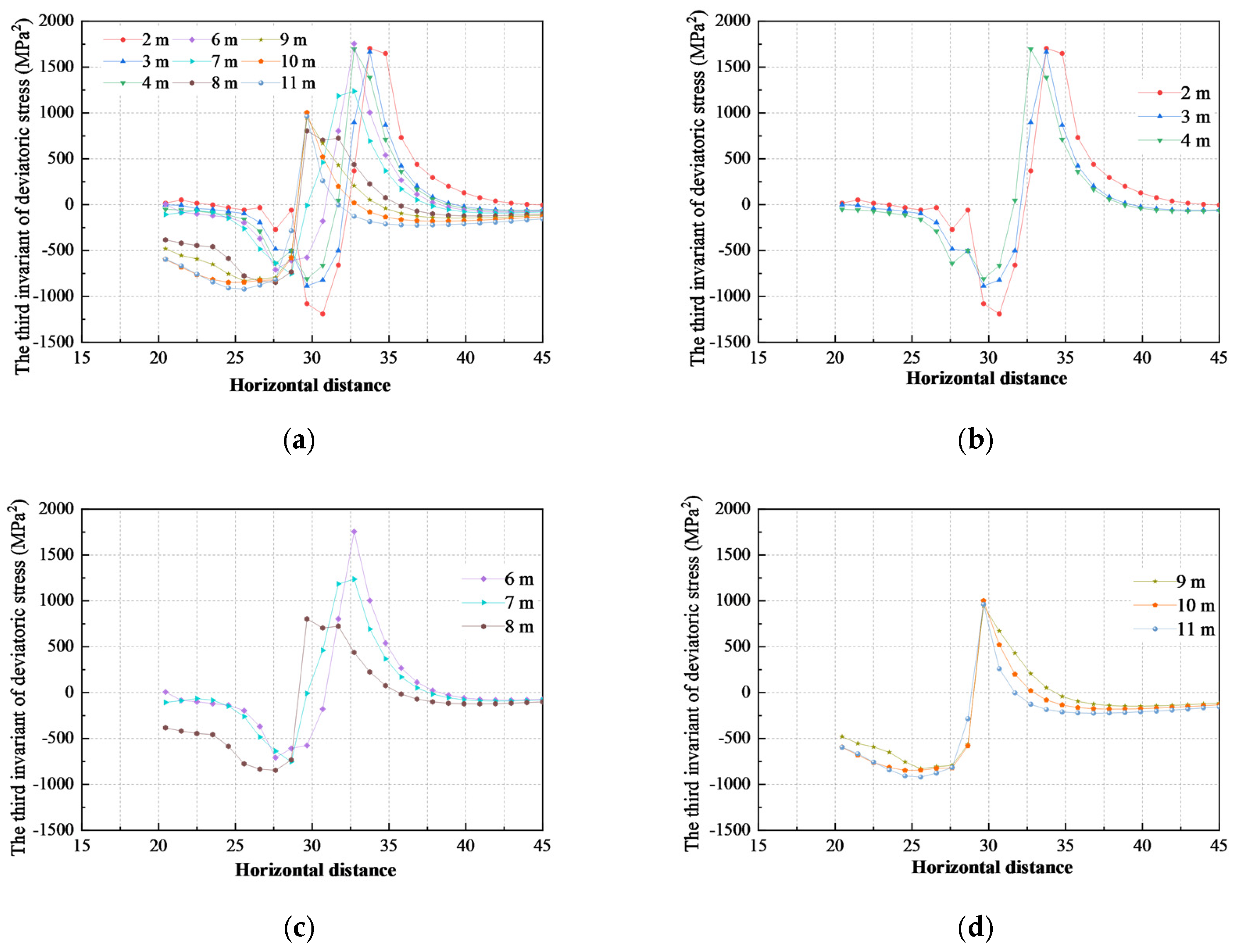
The distribution of the third invariant (J3) of deviatoric stress within various roof strata horizons of the 5307 track entry (the gob-side entry formed by roof cutting) under the influence of advanced mining abutment pressure is illustrated in Figure 14.
As illustrated in Figure 14,
(1)
Along the horizontal direction, the third invariant of deviatoric stress (J3) within 20 m on both sides of the 5307 track entry exhibits an “inverted saddle” distribution. From the rib to the deep coal mass, the transverse distribution of the strain state in the roof strata at various levels follows the sequence: low-intensity compressive strain, high-intensity compressive strain, and plane-strain state. The rock strata directly above the roadway are in a low-intensity compressive-strain state; the overlying strata of the shallow coal mass on both sides of the roadway are in a relatively high-intensity compressive-strain state; and the overlying strata of the deep coal mass on both sides of the roadway exhibit J3 values approaching zero, indicating a transition toward the plane-strain state. It should be noted that positive J3 values appear in the high-level strata of the deep coal mass at the 5307 working face, indicating a low-intensity tensile-strain state. This suggests that, under the influence of mining-induced abutment pressure, the high-level roof on the deep side of the gob-side rib exhibits a tendency toward tensile failure.
(2)
Similarly to the distribution of the second invariant, the third invariant of deviatoric stress in the roof strata directly above the roadway also demonstrates pronounced asymmetry. The compressive-strain intensity in the roof on the non-gob-side rib is greater than that on the gob-side rib, indicating that the directional pre-splitting on the gob-side roof has achieved a certain degree of pressure relief. The distribution characteristics of the third invariant of deviatoric stress vary with roof height: from the low-level to the high-level roof strata, the compressive-strain intensity gradually decreases, J3 approaches zero, and the strain state tends to transition toward plane strain.
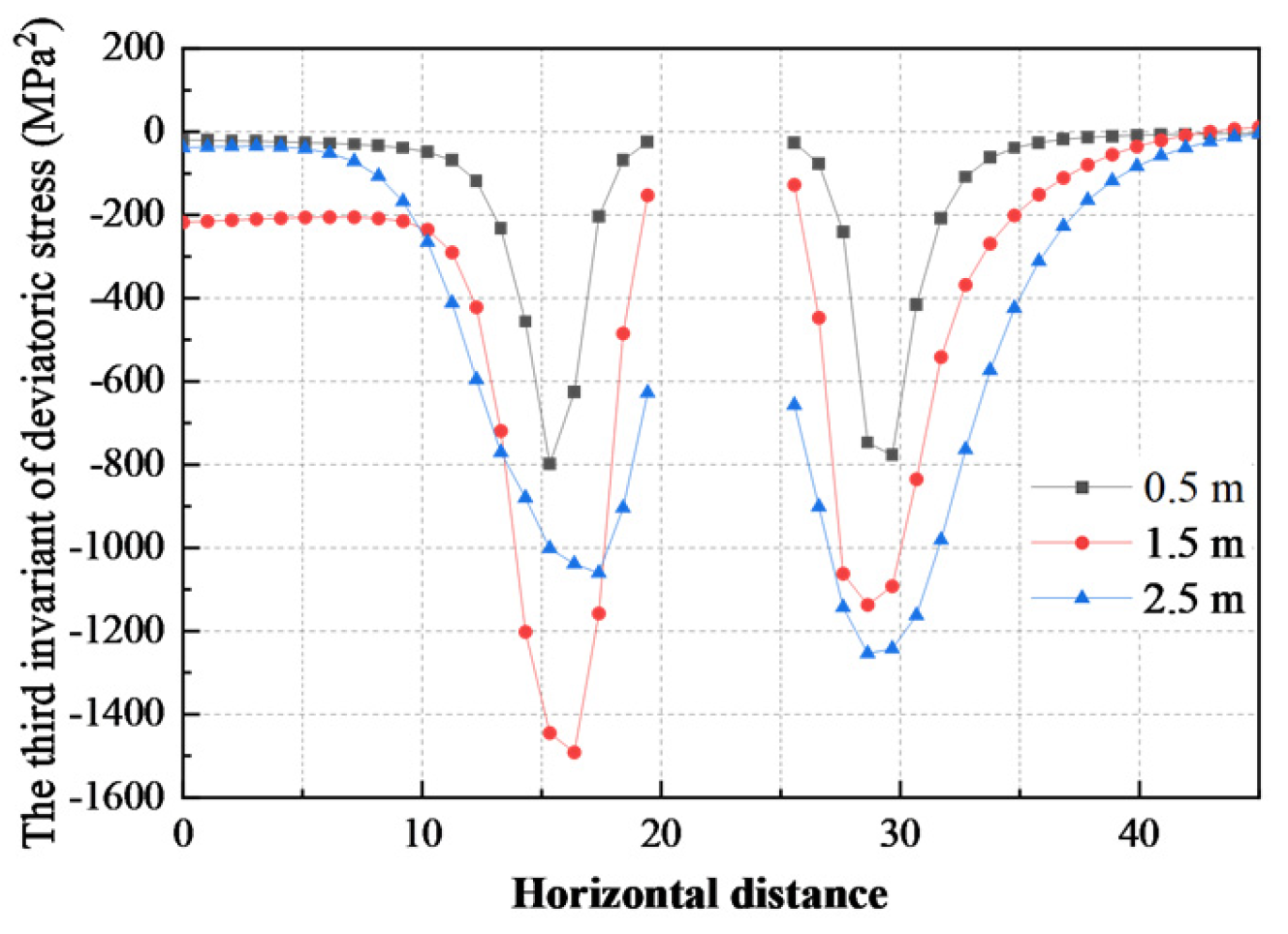
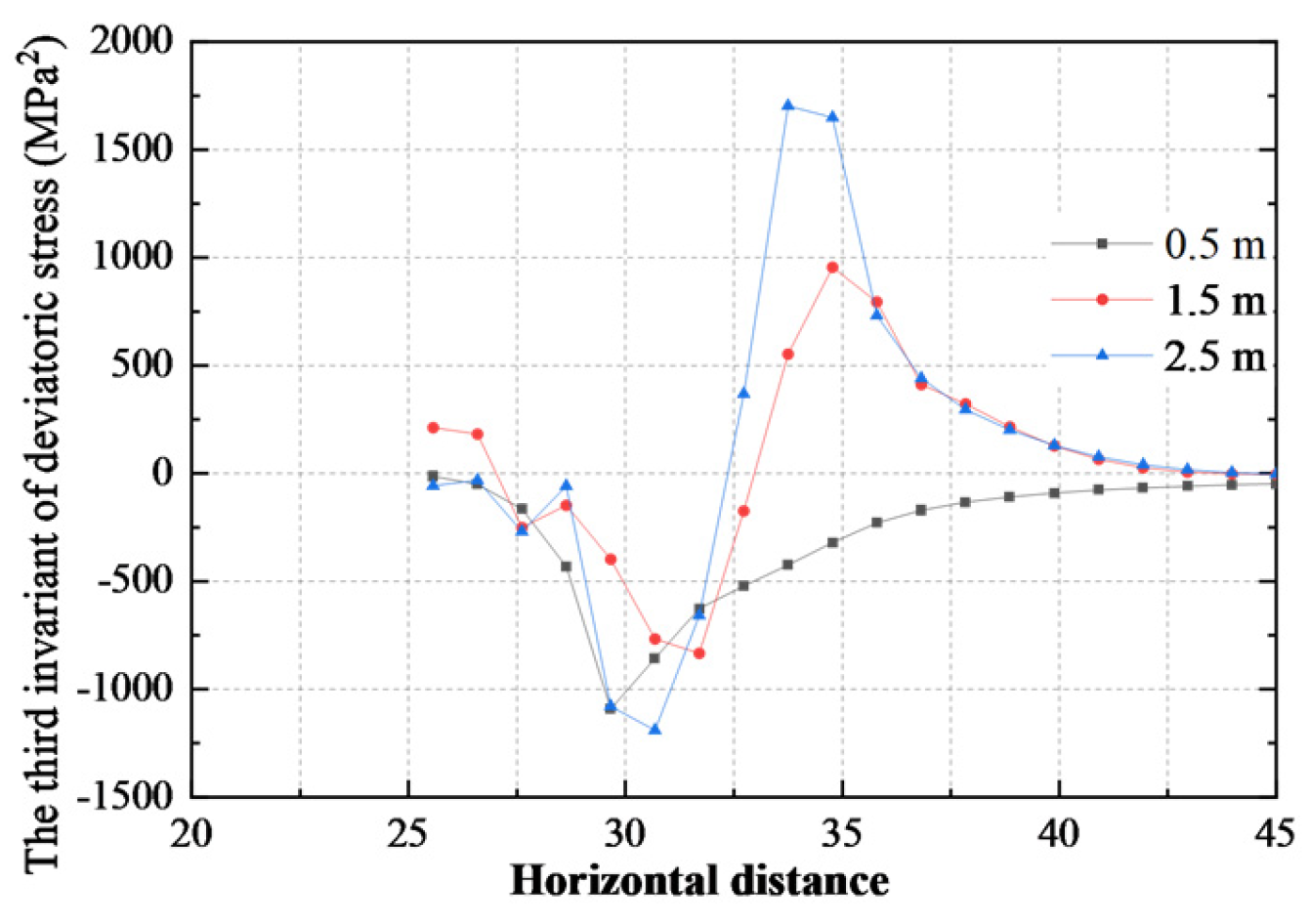
The distribution of the third invariant J3 of deviatoric stress on both sides of the 5307 working face track gateway under the influence of advanced mining abutment pressure is shown in Figure 15.
As illustrated in Figure 15, the J3 values within the solid coal located up to 15 m from the entry rib are negative, denoting a compressive-strain state. Beyond this 15 m threshold, the J3 values of the coal seam approach zero, indicative of a plane-strain state. Specifically, the deep zone situated 3–5 m from the entry rib experiences a high-intensity compressive-strain state. Consequently, moving from the entry rib deeper into the coal mass, the strain state of the coal seam sequentially evolves through the following stages: low-intensity compressive strain–high-intensity compressive strain–low-intensity compressive strain–plane-strain state. Furthermore, the compressive-strain intensity exhibits a pronounced lateral asymmetry across the entry, with the magnitude on the mining side significantly exceeding that on the non-mining side.

3.1.4. Displacement Distribution Characteristics

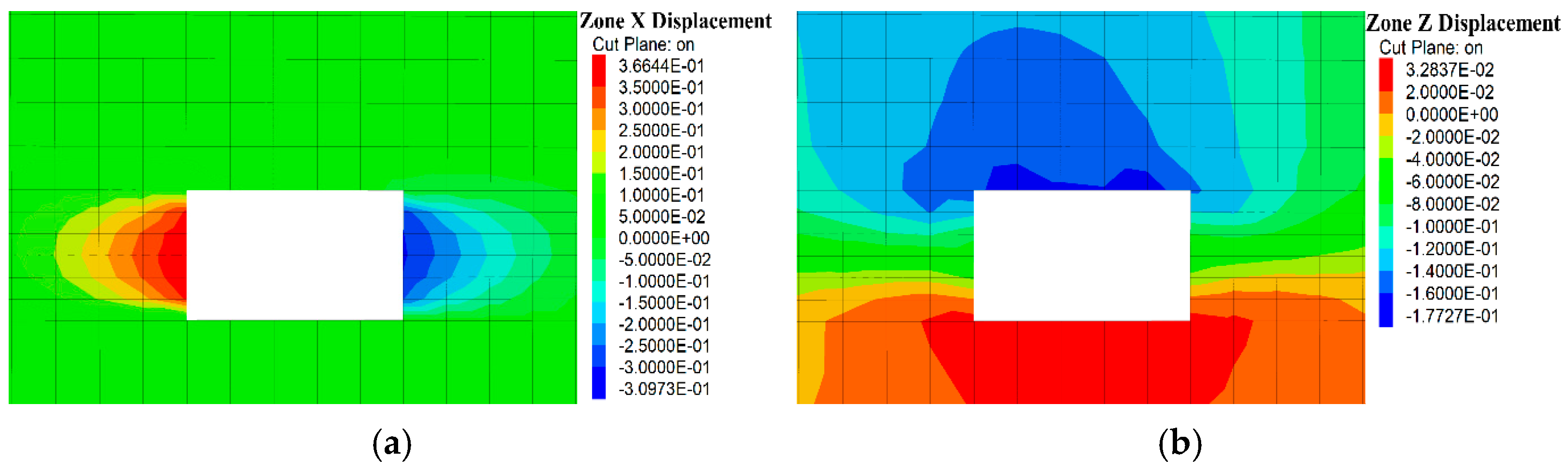
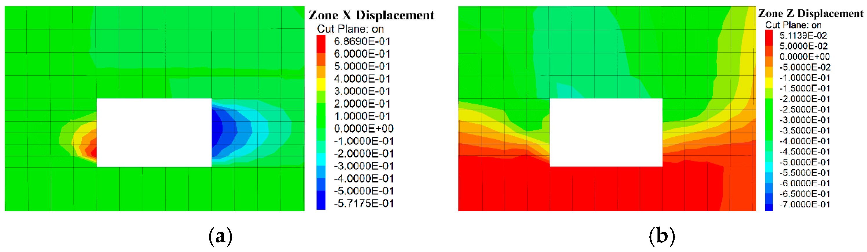
The horizontal and vertical displacement distributions of the surrounding rock within the track entry at a position 10 m ahead of the 5307 working face are illustrated in Figure 16. Affected by the advanced mining-induced abutment pressure, the horizontal displacement on the mining side of the 5307 track entry is greater than that on the non-mining side. Concurrently, deformation at the mid-height of the entry rib is more significant than that in its upper and lower sections. Due to the influence of directional roof pre-splitting blasting, the vertical displacement distribution of the roof exhibits a pronounced asymmetry, with the roof subsidence near the mining side being visibly larger than that near the non-mining side.

3.1.5. Deviatoric Stress Invariants and Displacement Distribution Characteristics in the Post-Mining Entry-Forming Stage

Following working face extraction, the roof on the gob side collapses along the pre-split plane. The roof structure of the gob-side entry retained by roof cutting and pressure relief comprises a low-horizon short cantilever beam formed by the roof cutting and an overlying stable high-horizon rock beam. The caved gangue within the gob is gradually compacted to form one flank of the retained entry; together with the solid coal rib and the floor, it constitutes the integrated surrounding rock system of the gob-side entry retained by roof cutting. Evaluating the stability of the surrounding rock within this entry-retaining section via numerical simulations can provide theoretical guidance for formulating effective ground-control countermeasures during the post-mining phase. To investigate the surrounding rock stability in the post-mining section of the 5307 track entry, the distribution characteristics of the second and third invariants of deviatoric stress within the surrounding rock were analyzed at a position 30 m behind the working face.
Distribution Characteristics of the Second Invariant of Deviatoric Stress
The distribution of the second invariant of deviatoric stress in rock layers at different heights of the roof in the post-mining entry-forming section of the 5307 working face track drift is illustrated in Figure 17.
(1)
J2 within the roof shows a single-peak distribution horizontally, peaking 5–10 m from the entry rib into the solid coal mass (5305 side). The J2 values of the roof strata within a specific horizontal range flanking the solid-coal side increase significantly. The peak J2 values across various horizons are concentrated within a horizontal distance of 5–10 m from the entry rib, delineating a pronounced stress concentration zone that stores a substantial amount of distortion energy. Notably, while the peak J2 value on the solid-coal side within the advanced section remains below 300 MPa2, it abruptly escalates to approximately 700 MPa2 within the post-mining entry-retaining section. This phenomenon occurs because, following the extraction of the 5307 working face, the support strength provided by the caved gangue in the gob to the overlying strata is inherently lower than that of the unmined coal mass. Consequently, the low-horizon short cantilever beam and high-horizon rock beam undergo varying degrees of bending and rotation during the post-mining stage, leading to a further elevation of the roof J2 values over the solid coal compared to the advanced section.
(2)
The distribution of the roof J2 within the post-mining entry-retaining section exhibits a pronounced lateral asymmetry. The J2 magnitude on the solid-coal side is significantly greater than that on the side adjacent to the gob, with the roof near the gob side storing less distortion energy. This confirms that post-extraction, the low-horizon rock strata within the roof-cutting boundary detach to form a short cantilever beam structure; the subsequent rotation of this cantilever beam forces the overlying strata on the solid-coal side to accumulate more distortion energy.
(3)
Unlike the advanced section, J2 peak locations vary across roof horizons post-mining. Specifically, the horizontal peak positions of the low-horizon strata are located further from the entry than those of the high-horizon strata. The horizontal distance of the J2 peak is 7.5–10.0 m from the entry rib for the low-horizon roof strata, 5.0–7.5 m for the mid-horizon roof strata, and less than 5.0 m for the high-horizon roof strata. This spatial hierarchy demonstrates that the distortion zone of the high-horizon roof is tightly confined, whereas that of the low-horizon roof strata is significantly expanded, resulting in relatively poorer structural stability in the lower horizons.
(4)
The peak J2 values of the roof strata decrease progressively with increasing horizon height. The high-horizon roof stores lower distortion energy and maintains favorable stability, whereas the low-horizon roof strata exhibit elevated J2 magnitudes, highlighting their structural vulnerability. Therefore, for effective ground control within the post-mining entry-retaining section, it is essential to implement active support measures that strengthen the mechanical interlocking between the low- and high-horizon roof strata. Concurrently, temporary internal supports must be deployed within the entry to compensate for the bearing capacity loss resulting from gob caving.
The distribution of the second invariant of deviatoric stress within the solid-coal side of the post-mining entry-retaining section of the 5307 track entry is illustrated in Figure 18.
Distribution Characteristics of the Third Invariant of Deviatoric Stress
The distribution of the third invariant of deviatoric stress within the overlying rock strata at different heights within the post-mining entry-retaining section of the 5307 track entry is illustrated in Figure 19.
As illustrated in Figure 19,
(1)
Horizontally, extending from the entry rib into the deep solid coal mass (5305 working face), the third invariant of deviatoric stress within the overlying rock begins with a negative value, decreases to a negative peak, rises back to zero, crosses into positive territory to form a positive peak, and subsequently recedes to zero. Consequently, both the positive and negative regimes exhibit a distinct “single-peak” distribution profile. Moving from the entry rib into the deep solid-coal side, the corresponding strain states of the overlying strata sequentially evolve through the following stages: compressive-strain–tensile-strain–plane-strain state.
(2)
Vertically, within the roof strata overlying the entry, J3 transitions from positive to negative from bottom to top. This indicates that with increasing horizon height, the roof rock layers transition from low-intensity tensile-strain and plane-strain states into a dominant compressive-strain state. Flanking the solid-coal side, the horizontal locations of these J3 peaks vary distinctly across different strata horizons, with both the positive and negative peak positions within the low-horizon strata situated further from the entry rib than those within the high-horizon strata. Specifically, for the roof strata in a compressive-strain state (J3 < 0), the horizontal distances of the J3 peaks from the entry rib migrate from 5.0 m to 2.5 m, and down to 1.0 m as the horizon shifts from low to high positions. Conversely, for the strata in a tensile-strain state (J3 > 0), the horizontal peak distances for the low-, mid-, and high-horizon strata are 7.5–10.0 m, 4.0–7.5 m, and 4.0 m from the entry rib, respectively. The low-horizon roof strata exhibit a significantly wider transition zone between tensile and compressive-strain states, compromising their structural stability relative to the high-horizon roof. In conjunction with the horizontal distribution of J3 across each layer, the low-horizon roof strata within the entry-retaining section are highly susceptible to fracturing within a zone approximately 10.0 m from the entry rib. Therefore, during ground control in the post-mining entry-retaining stage, temporary internal support within the entry must be reinforced to mitigate roof bending and deformation.
The single-peak distribution of deviatoric stress invariant J2 exists consistently in low-, medium-, and high-level roof strata behind the working face. The difference lies in the horizontal position of the peak: the J2 peak of low-position roof is farthest from the roadway rib, while the peak of high-position roof is closest to the entry, which reflects the expanding failure range of shallow roof rock. No bimodal or saddle-shaped distribution appears in any roof horizon in the post-mining section.
The distribution of the third invariant of deviatoric stress within the solid-coal side of the post-mining entry-retaining section of the 5307 track entry is illustrated in Figure 20.
Horizontally, the third invariant of deviatoric stress within the near-floor zone (0.5 m) of the solid coal rib remains negative, signifying a dominant compressive-strain state. Conversely, within the mid-height (1.5 m) and upper (2.5 m) zones of the coal rib, J3 transitions from negative to positive values before eventually approaching zero when moving from the shallow to the deep sections of the solid coal mass, indicating that certain deep coal zones undergo tensile strain. On the rib surface, the J3 values at the upper and lower sections are negative or close to zero, corresponding to a low-magnitude compressive-strain state, whereas the value at mid-height is positive, reflecting a low-magnitude tensile-strain state. This phenomenon is primarily attributed to the pronounced bulging deformation occurring at the mid-height of the solid coal rib, which induces localized tensile stress in this region.
Displacement Distribution Characteristics
Figure 21 presents the cloud maps of horizontal and vertical displacement distributions of surrounding rock in the 5307 track gateway at 30 m behind the working face.
The maximum displacement of the broken rock rib occurs within its mid-to-lower section, whereas the peak deformation of the solid coal rib is concentrated at its mid-height.
Furthermore, the asymmetric distribution of the roof’s vertical displacement becomes significantly more pronounced within the post-mining entry-retaining section, characterized by a substantially larger roof subsidence on the gob side than on the solid-coal side.
Only two numerical schemes (consistent with actual mining layouts) were established; hypothetical single-factor control groups lack on-site implementability. Instead, we decouple the independent effect of each CRRE core component via multi-index analysis of simulation and monitoring results:
(1)
Pillar elimination: The 20.1% average reduction in advance abutment pressure (Figure 9 and Figure 10) quantitatively reflects the prominent stress relief effect after removing high-stress coal pillars.
(2)
Directional roof cutting: The asymmetric J2 deviatoric energy distribution (Figure 12, Figure 13, Figure 14 and Figure 15) proves that pre-splitting fractures cut off overburden stress transfer and reduce roof energy accumulation independently.
(3)
Gangue retaining and NPR asymmetric support: Post-mining displacement laws (Figure 17, Figure 18, Figure 19, Figure 20 and Figure 21) and field-monitoring data (max roof subsidence 180 mm, max floor heave 329 mm) verify that the combined support system effectively restrains asymmetric roadway deformation.
In short, the respective mechanical contributions of pillar removal, roof cutting, and asymmetric support can be clearly distinguished through the above comprehensive analysis, even without additional single-factor models.

3.2. Control Measure of Roof Asymmetric Deformation

The surrounding rock structure transforms from dual solid coal walls pre-mining to a gob gangue wall plus solid coal wall post-mining. Throughout the entry retention process, the stable preservation of the entry is dictated by a mechanical interplay: the subsidence and rotation of the roof, coupled with the dilatation-compaction behavior of the caved rock mass within the gob. Consequently, an integrated “pre-mining and post-mining collaborative control strategy” for the surrounding rock is proposed. As shown in Figure 22, prior to mining, roof stability is enhanced via active high-strength support to fully leverage the self-bearing capacity of high-horizon rock beams; concurrently, directional pre-splitting is executed to prematurely decouple the roof continuity between the working face and the entry, thereby controlling the cutting boundary and setting optimal conditions for the low-horizon roof to form a short cantilever beam structure. Post-mining, high-strength temporary internal supports are deployed within the entry to rigorously suppress roof subsidence and rotation.
Figure 22. Active roof control.
Processes 14 02605 g022
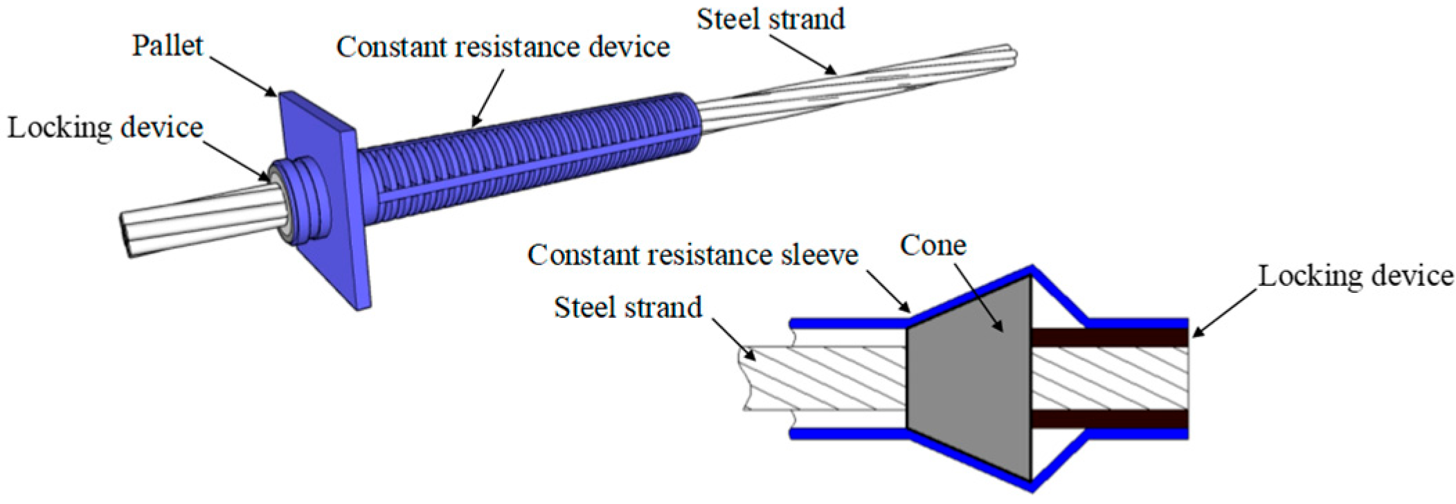
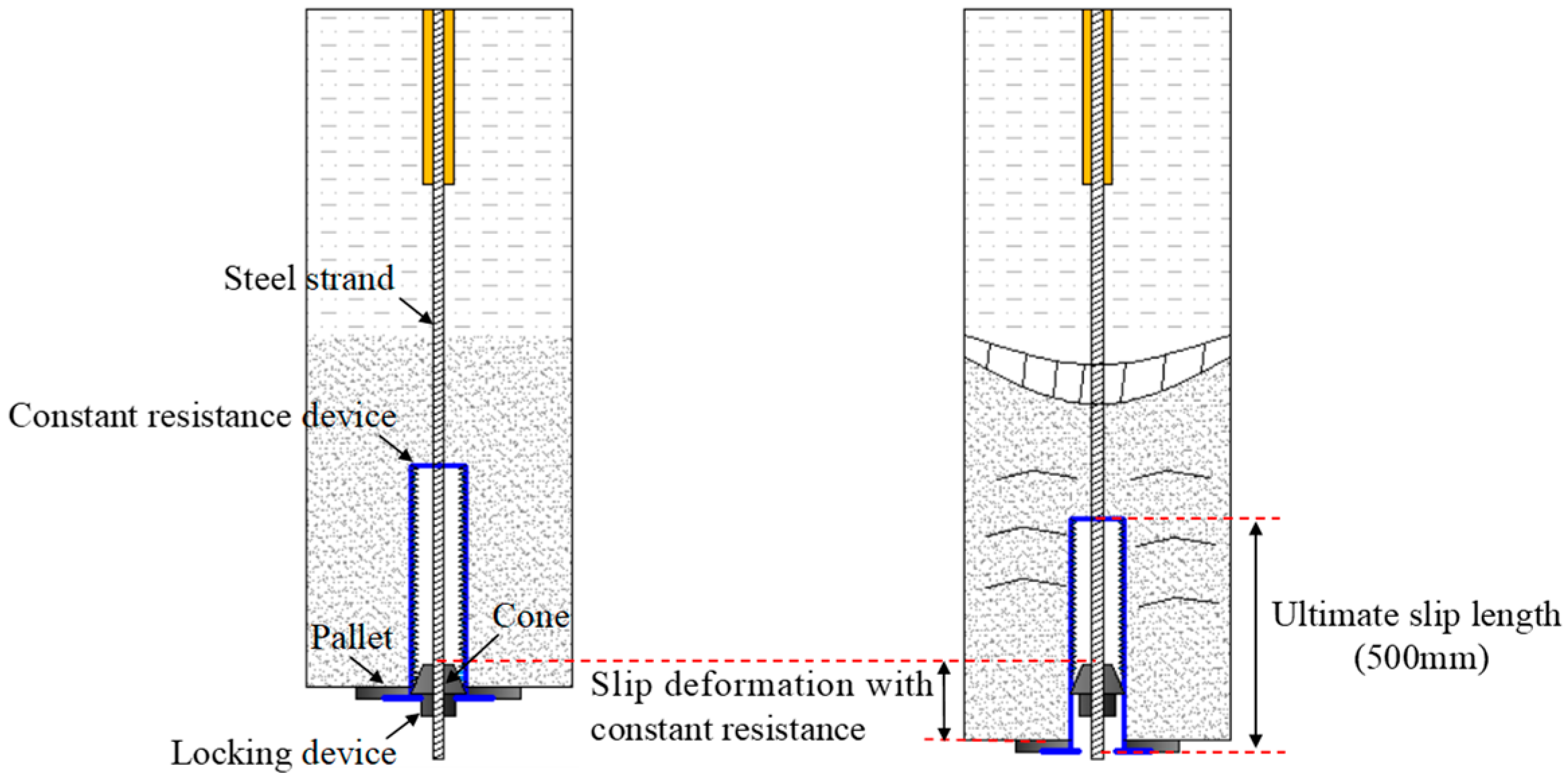
The NPR anchor cable comprises a constant-resistance device, a steel strand, a bearing plate, and an anchor lock. The device is fitted onto the free strand end and immobilized by the plate and lock. Figure 23 shows the schematic diagram of the NPR constant-resistance anchor cable configuration. Structurally, a conical wedge is embedded within the sleeve of the constant-resistance device, with its outer diameter slightly exceeding the inner diameter of the sleeve wall. This unique “cone-and-sleeve” assembly constitutes the core negative Poisson’s ratio structure, enabling the NPR anchor cable to maintain a steady working resistance, absorb exceptional energy, and accommodate large-scale rock mass deformations. The detailed mechanical configuration of this NPR constant-resistance device is depicted in Figure 24.
Based on the structural analysis and supporting mechanism of the NPR constant-resistance anchor cable, this system not only accommodates large deformations of the surrounding rock through the internal relative slippage of its components, but also maintains a steady working resistance and absorbs strata deformation energy via its negative Poisson’s ratio effect. Concurrently, the dynamic impact energy generated by pre-splitting blasting exerts a profound disturbance on the roof strata flanking the cut side. Considering the structural characteristics of the post-mining short cantilever beam, the roof zone adjacent to the cut side of the 5307 track entry at Anju Coal Mine is designated as the critical control position. Consequently, aligned with the geomechanical principles of gob-side entry retaining by roof cutting and the lithological attributes of the 5307 working face roof, an asymmetric roof reinforcement scheme featuring an “NPR constant-resistance anchor cable + W-steel band” configuration is developed to augment the original entry support. The specific design parameters are detailed below:
(1)
Key parameters of roof cutting: The directional roof cutting height is set at 7000 mm with an inclination angle of 15°, and the blast hole spacing is fixed at 500 mm. The above parameters are determined by combining theoretical calculations and existing ultra-deep engineering practices. The mining height of 2 m corresponds to a calculated immediate roof caving height of 6.8 m; therefore, a 7 m cutting height is adopted to thoroughly disconnect the stress transfer of the immediate roof. The 15° cutting angle is selected to eliminate severe extrusion between the pre-split fracture plane and entry roof, which effectively reduces asymmetric roof subsidence [38,41].
(2)
Within the intact roof section, the blasting charge configuration is 5 + 3 + 3 + 2 (13 cartridges) with a stemming length of 2000 mm. Conversely, for the fractured roof section, the charge configuration is adjusted to 5 + 4 + 1 (10 cartridges) with a stemming length of 2500 mm. This segmented charging scheme is optimized based on smooth pre-split blasting theory and 16 groups of field comparative blasting tests. A longer stemming length for fractured roof weakens blasting vibration disturbance under ultra-high in situ stress, preventing premature roof fragmentation before cutting formation.
(3)
The blast hole charge structure was determined by combining the directional pre-splitting blasting fracture calculation theory and field multi-group single-hole blasting tests. Based on the rock compressive strength and buried depth of the ultra-deep roadway, the theoretical charge quantity was first calculated by the smooth blasting formula, then adjusted and optimized through 16 groups of field blasting comparison tests on intact and fractured roof sections, respectively, to obtain the final segmented charge schemes. A total of 80 test blast holes were constructed in these field comparative tests.
(4)
Unified construction error control standards were formulated during field implementation: cartridge filling error controlled within ±0.2 rolls, stemming length error within ±50 mm, and detonator initiation delay time error limited to ±10 ms, and all construction deviations were recorded and counted. Sensitivity analysis of blasting parameters shows that within the above error range, the blasting energy can form a continuous pre-splitting fracture plane without excessive energy overflow to produce strong dynamic disturbance. The segmented charge design reduces instantaneous blasting vibration intensity, effectively avoiding dynamic instability of surrounding rock under high in situ stress in ultra-deep mines, ensuring stable construction repeatability of the roof cutting scheme.
(5)
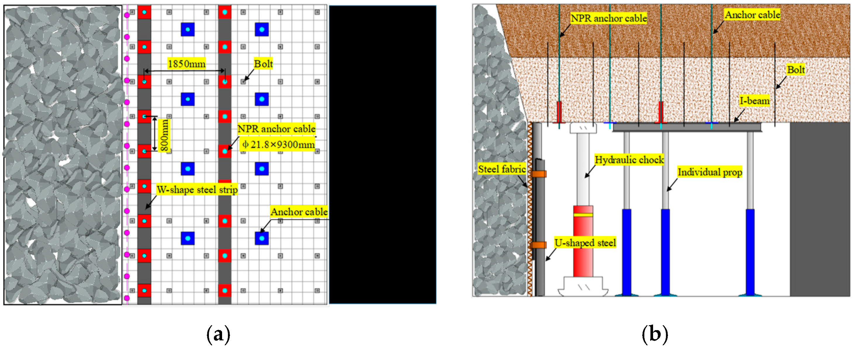
Key parameters of roof support: Supplementing the baseline support, two lines of NPR constant-resistance anchor cables (dimensions: 9300 mm × 21.8 mm) are installed within the roof of the 5307 track entry. These anchor cables are arranged in a grid spacing of 1850 mm × 800 mm and are structurally interconnected along the entry axis via W-steel bands. The 9.3 m cables anchor into stable high-level sandstone; 1850 mm × 800 mm spacing limits asymmetric convergence below the 500 mm threshold. W-steel belts provide continuous surface restraint to eliminate local roof separation.
(6)
Key parameters of gangue retention: A composite structure consisting of “steel mesh + telescopic U36 section steel props” is deployed for gob gangue isolation. The center-to-center spacing of the telescopic U36 steel props is 500 mm; the upper and lower elements feature a retractable lap joint, with each individual section measuring 2500 mm in length.
(7)
Temporary roof control support parameters: The temporary roof reinforcement zone extends across a 300 m range lagging the advancing working face. Field monitoring shows surrounding rock deformation stabilizes 250 m behind the working face; a 300 m temporary support range is reserved as a safety margin to cover the full rapid and decelerated deformation stage before roadway stabilization. Advanced hydraulic support units are arranged along the cut line with a center-to-center interval of 4800 mm, utilizing a “one-beam, three-column” framework spaced at 800 mm per set. Furthermore, four rows of “one-beam, four-column” temporary support frames are erected between the front and rear adjacent units, maintaining a strict row spacing of 800 mm.
The established numerical model adopts measured geological parameters and laboratory test indices for main rock strata, and key gob constitutive parameters are calibrated by the classic Salamon compaction theoretical curve to reduce artificial parameter deviation. Parameter sensitivity pre-analysis shows that roadway surrounding rock deformation is mainly controlled by roof rock strength and coal pillar stress concentration effect; small fluctuations in elastic parameters and gangue friction angle will not change the overall difference law of the two support schemes. Therefore, the comparative advantage of the CRRE retaining entry scheme relative to the conventional coal pillar scheme is stable and reliable, and the deformation and stress differences reflected in Figure 9, Figure 10, Figure 11, Figure 12, Figure 13, Figure 14, Figure 15, Figure 16, Figure 17, Figure 18, Figure 19 and Figure 20 are deterministic overall structural differences rather than random calculation errors.

3.3. Field Test and Field Monitoring

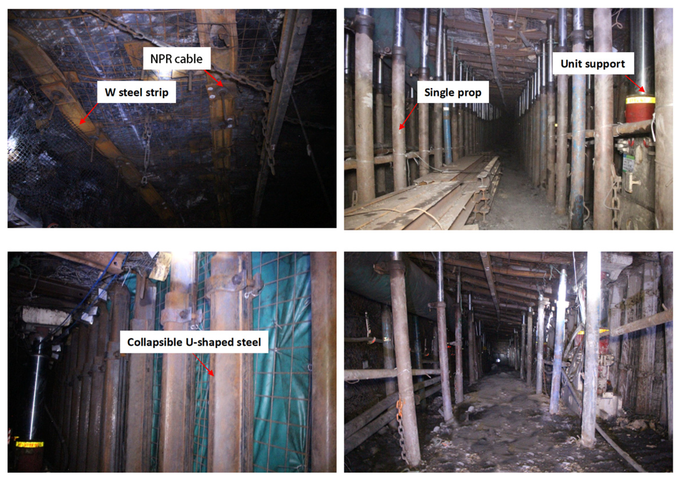
Integrated with the actual production conditions of the 5307 working face at Anju Coal Mine, the total length of the gob-side entry retaining section is 480 m. Based on the aforementioned research findings, surrounding rock reinforcement support is implemented within the entry prior to panel extraction. Post-mining, gangue-retaining support structures are deployed along the gob boundary, while temporary internal support facilities are strategically arranged within the entry. The comprehensive field-scale support scheme is illustrated in Figure 25.
A total of four monitoring sections (W1, W2, W3, W4) were arranged uniformly along the 480 m retained entry.
Four sections (W1–W4) at 0, 120, 240, and 360 m were monitored until stabilization (260–270 m behind the face). W3 served as the primary station.
All displacement sensors adopt built-in temperature compensation modules to eliminate the measurement error caused by ultra-deep high geotemperature. Monitoring records were continuously collected until surrounding rock fully stabilized at each section.
NPR constant-resistance anchor cable tension and shrinkage monitoring: The surrounding rock structure and stress state of the gob-side retained entry undergo dynamic evolution from the initial roof-cutting stage until ultimate entry stabilization. Consequently, support provided by NPR constant-resistance anchor cables is paramount to the roof control of the roof-cutting entry. By monitoring real-time variations in cable tension and shrinkage, the evolving stress state of the entry roof can be dynamically captured. This continuous tracking provides a critical foundation for optimizing support parameters and determining the precise timing for the withdrawal of temporary internal supports post-mining.
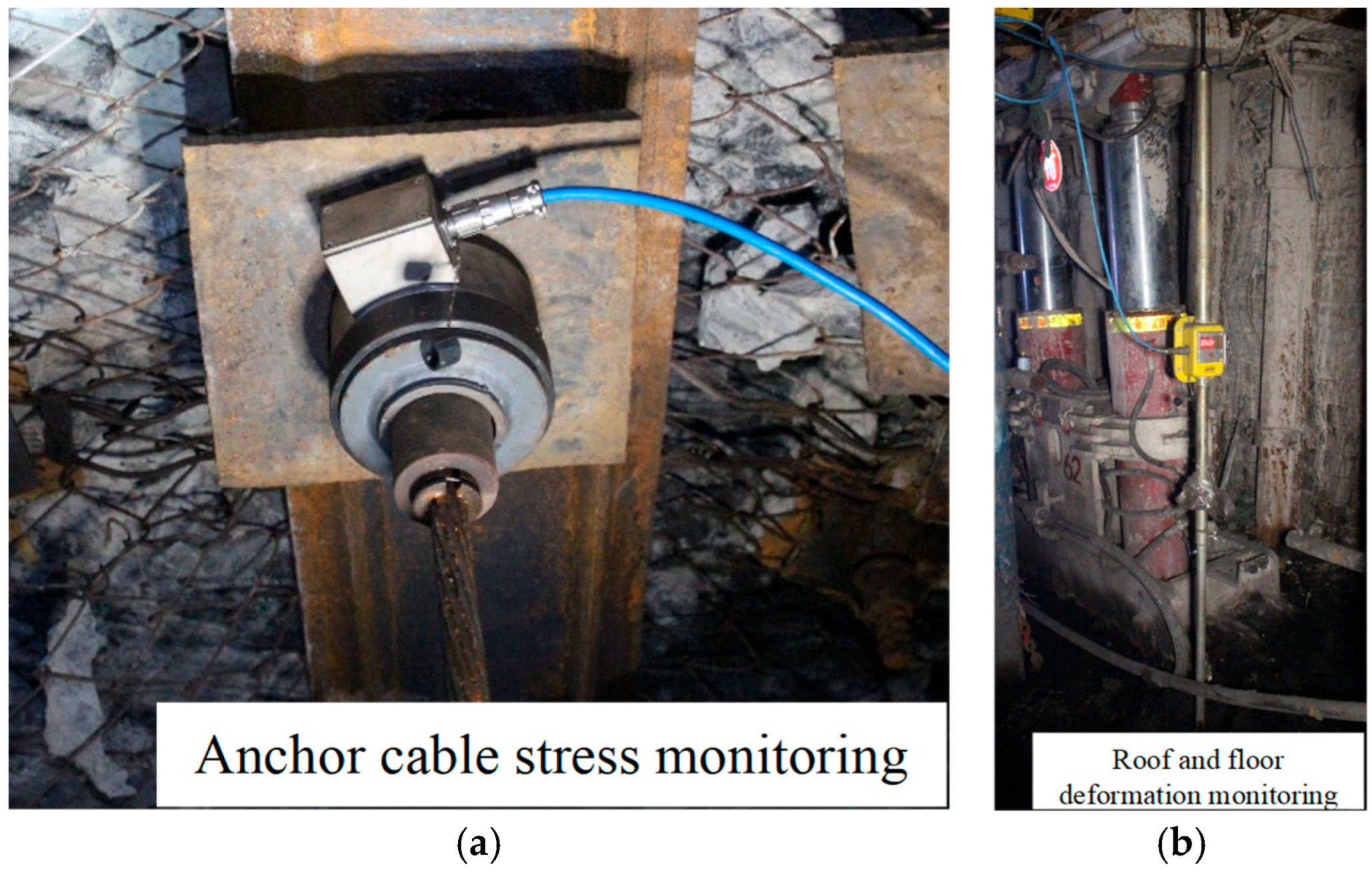
Entry surface displacement monitoring: As the most direct indicator of surrounding rock stability, entry surface displacement serves as a crucial metric for evaluating the effectiveness of entry retention and timing the removal of temporary supports. As shown in Figure 26, by integrating surface asymmetric displacement data with roof separation and constant-resistance anchor cable slippage measurements, the structural evolution law and stress transfer paths of the entry roof can be comprehensively elucidated.
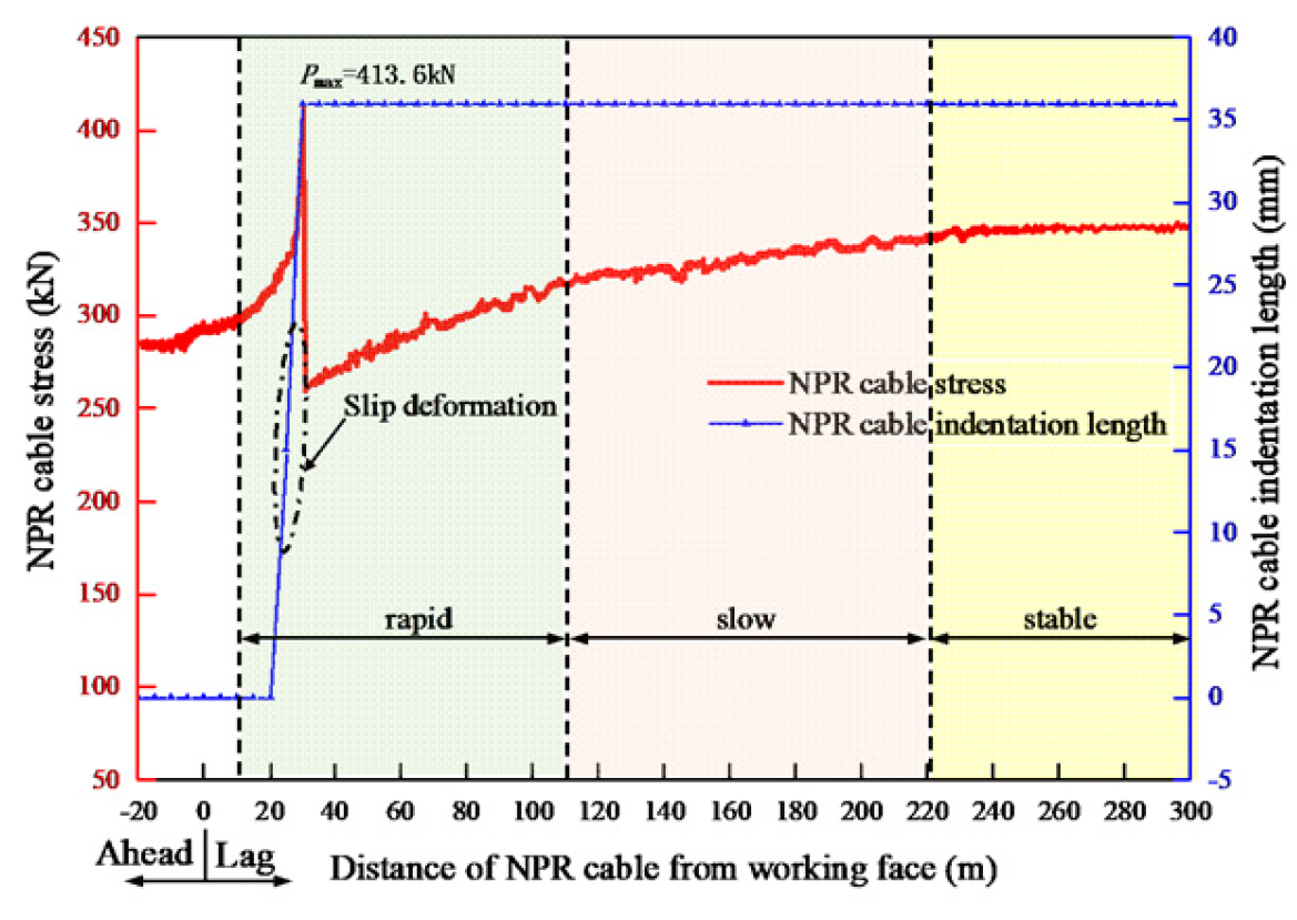
(1)
NPR cable tension evolves through four stages: slow advance-influence growth, post-mining rapid growth, decelerated accumulation, and ultimate stabilization.
(2)
Cable tension initiates its upward trend at 22 m ahead of the advancing working face, a phenomenon primarily triggered by the mining-induced advanced abutment pressure. Within this pressure-influenced zone, the tension of the NPR anchor cable increases at a moderate rate. Conversely, within a zone of 5 to 10 m lagging the working face, the caving process of the gob roof exerts a severe “pulling” effect on the retained entry roof, significantly accelerating the tension growth rate of the anchor cable.
(3)
Starting from a position 90 m to 130 m lagging the working face, the large voids within the caved gob gangue undergo gradual compaction under the intense strata pressure, shifting the anchor cable tension into a stage of slow, decelerated increase.
(4)
Beyond a distance of 230 m to 250 m lagging the working face, the high-horizon strata tend toward equilibrium as the gob gangue achieves maximum compaction. Consequently, the surrounding rock enters a steady state, and the tension of the NPR constant-resistance anchor cable stabilizes without significant fluctuations.
(5)
Once the tension sustained by the anchor cable exceeds its rated constant-resistance threshold (330 kN), the conical wedge within the constant-resistance device undergoes relative structural slippage. Field statistical data reveal that the maximum structural retraction of the constant-resistance anchor cable reaches 54 mm. This deformation behavior demonstrates that the NPR anchor cable effectively exerts active support while capturing and absorbing energy induced by roof subsidence.
Figure 26. Anchor cable stress and roof and floor deformation monitoring: (a) anchor cable stress monitoring; (b) roof and floor deformation monitoring.
Processes 14 02605 g026
For the monitoring equipment adopted in this test, vibrating-wire pressure sensors were used to collect cable tension data. The sensor precision is ±0.5 kN. Under normal mining conditions, the data sampling frequency was set to once per hour; within the 30 m advanced disturbance zone ahead of the working face, the sampling interval was shortened to 10 min to record rapid stress variations. All sensors and data acquisition instruments were comprehensively calibrated in a rock mechanics laboratory 15 days before underground installation, and secondary field calibration was carried out after anchor cable tensioning to eliminate installation errors. Full calibration records and raw monitoring data are retained for inspection. The field monitoring results are presented in Figure 27.
Figure 27. Stress and indentation curve of NPR constant resistance anchor cable.
Processes 14 02605 g027
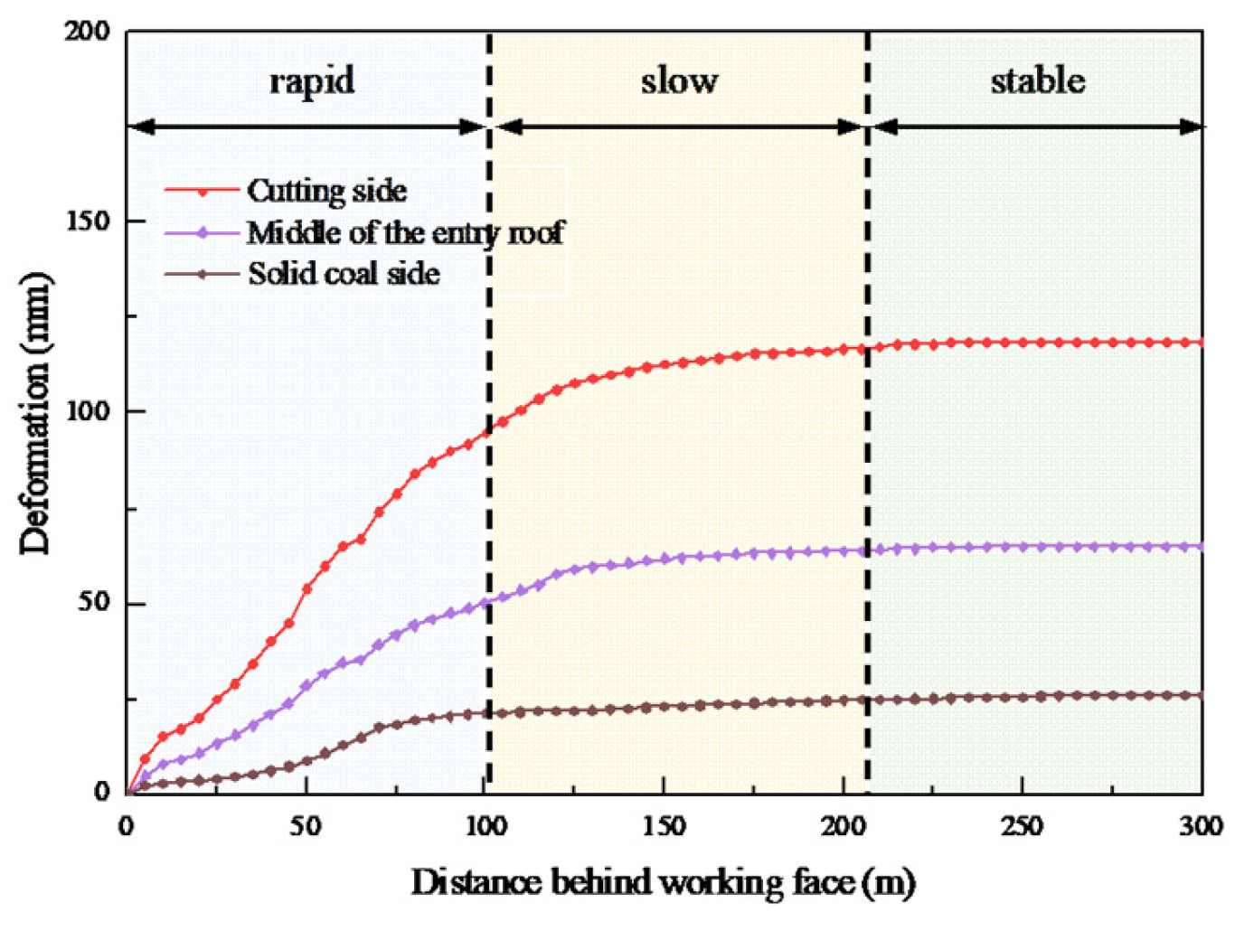
The roof-to-floor convergence of the retained entry also exhibits pronounced asymmetric characteristics. Upon reaching structural equilibrium, the final roof subsidence measured at the W3 monitoring station follows the decreasing order of cut side > entry center > solid-coal side. Specifically, the roof deformation within a distance of 102 m lagging the working face is characterized by a rapid subsidence stage, whereas it transitions into a stabilization stage beyond a lag distance of 210 m. The maximum roof subsidence values are recorded as 180 mm at the cut side, 93 mm at the entry center, and 34 mm adjacent to the solid-coal side. It should be clarified that the deformation severity hierarchy “cut side > entry center > solid-coal side” only describes roof subsidence. For total roof-floor convergence (roof subsidence + floor heave), the deformation order changes to entry center (422 mm) > cut side (415 mm) > solid-coal side (306 mm).
Conversely, the magnitude of floor heave follows a different sequence: entry center > solid-coal side > cut side. The floor deformation develops rapidly within 96 m lagging the working face and tends toward stability at a lag distance of 223 m. The final floor heave reaches 235 mm at the cut side, 329 mm at the entry center, and 272 mm near the solid-coal side. Consequently, the total roof-to-floor convergence obeys the hierarchy of entry center > cut side > solid-coal side, with cumulative deformations measured at 422 mm, 415 mm, and 306 mm, respectively. The roof subsidence and floor heave curves of W1, W2, W3, and W4 sections show highly consistent evolution rules: rapid deformation within 0–120 m, decelerated deformation at 120–250 m, and stabilization after 250 m lagging the working face. The maximum roof subsidence of the four sections ranges from 172 mm to 186 mm, and floor heave ranges from 318 mm to 335 mm. Small numerical differences between sections verify the universality of the surrounding rock deformation law. For ultra-deep gob-side entry retaining roadways buried over 1100 m in this mine, the engineering control standard specifies that the allowable total roof-floor convergence shall not exceed 500 mm to meet ventilation and transportation requirements.
Exponential decay functions are adopted to fit the measured deformation data of each section. The piecewise fitting formula of entry total convergence s with lag distance x is obtained:
  • Rapid deformation stage (0 < x ≤ 120 m): s = 3.42x − 0.0071x2, average deformation rate v = 3.15 mm/m;
  • Deceleration stage (120 < x ≤ 250 m): s = 416.2 − 142.8e−0.0062x, average deformation rate v = 0.43 mm/m;
  • Stable stage (x > 250 m): The change rate of deformation curvature tends to 0, and the daily convergence increment is less than 0.1 mm.
The three-stage division is derived from W1–W4 monitoring data. Deformation rates decrease sharply after 120 m, with daily convergence below 0.1 mm beyond 250 m, consistent with numerical simulations.
Distinct differences in deformation rate quantitatively support the three-stage division of surrounding rock deformation. The deformation curves of the cutting side, roadway middle, and solid-coal side calculated by FLAC3D are highly consistent with the field-monitoring curves in Figure 28 in terms of variation trend and peak deformation, with the overall deviation less than 10%.
During the mining of the 5307 working face, the gob roof caved smoothly along the pre-split cutting plane, successfully achieving gob-side entry retaining under the protection of the joint support system. The deformation of the entry roof was effectively controlled by the coordinated temporary roof support network, which comprised pre-mining NPR constant-resistance anchor cable reinforcement, post-mining advanced unit supports, and individual hydraulic props. Upon reaching a state of geomechanical equilibrium, the final roof subsidence was restricted to 110–230 mm, while the functional entry width was maintained at 4350–4700 mm, demonstrating excellent cross-sectional structural integrity. Ultimately, a total length of 480 m of the 5307 track entry was successfully retained. This engineering achievement not only guaranteed safe extraction across the current working face but also fully satisfied the production and ventilation requirements for the subsequent panel. The field application results of the 5307 track entry retention are depicted in Figure 29. Mesh-induced numerical fluctuations only created small SD values (<0.8 MPa), much lower than the actual stress relief difference in the roof-cutting technique.
The monitoring section is arranged at the central position of the numerical model’s research roadway, and the deformation data of roof subsidence 180 mm and floor heave 329 mm are the average values of three continuous measuring sections along the test roadway. The calculated roadway surrounding rock deformation from FLAC3D is basically consistent with the field-measured deformation magnitude and deformation distribution characteristics, which verifies the accuracy of the established numerical model.

4. Conclusions

(1)
Peak J2 in the coal rib concentrates at 5–8 m depth, rendering the mid-height prone to failure. Roof strain transitions from compressive to plane strain from rib to deep coal mass, requiring proactive support to interlock lower and upper roof strata pre-mining.
(2)
The post-mining stability of the surrounding rock is further dictated by the redistribution of the deviatoric stress invariant. The peak J2 value within the post-mining entry roof concentrates within a zone 5–10 m from the entry rib, indicating poor structural integrity of the lower roof. Because the lower roof strata are highly prone to fracturing within this 10 m range, the temporary roof-control support intensity must be enhanced to mitigate roof bending and separation.
(3)
A spatiotemporal differential control strategy is proposed: directional pre-splitting pre-mining, active high-tension support to interlock roof blocks, and targeted roof control with rib protection post-mining.
(4)
Field-monitoring data from four measuring sections distributed along the strike demonstrate that the surrounding rock deformation of the roof-cutting entry exhibits distinct phased and asymmetric characteristics. The deformation evolution behind the working face is divided into three stages: rapid deformation (0–120 m behind the face), attenuated deformation (120–250 m), and asymptotic stabilization beyond 250 m. Spatially, the cumulative deformation intensity follows the order of cut side > entry center > solid-coal side. The maximum measured roof subsidence reaches 180 mm, and the floor heave reaches 329 mm.

Author Contributions

Conceptualization, L.Z. and C.H.; methodology, L.Z.; software, C.H.; validation, L.Z. and B.P.; formal analysis, C.H. and Y.L.; investigation, Y.J. and Y.L.; resources, B.P.; data curation, Y.J. and F.S.; writing—original draft preparation, L.Z.; writing—review and editing, L.Z. and C.H.; visualization, B.P.; supervision, F.S.; project administration, Y.J.; funding acquisition, B.P. All authors have read and agreed to the published version of the manuscript.

Funding

This research was funded by “the National Natural Science Foundation of China, grant number 42377195”, and “Science and Technology Project of China Huaneng Group Co., Ltd., grant number HNKJ25-H18”.

Data Availability Statement

The raw data supporting the conclusions of this article will be made available by the authors on request.

Conflicts of Interest

All authors were employed by Huaneng Coal Technology Research Co., Ltd. All authors declare that the research was conducted in the absence of any commercial or financial relationships that could be construed as a potential conflict of interest. The authors declare that this study received funding from China Huaneng Group Co., Ltd. The funder was not involved in the study design, collection, analysis, interpretation of data, the writing of this article, or the decision to submit it for publication.

References

  1. Luo, H.; Liu, Z.Y.; Ge, S.; Ding, L.L.; Zhang, L. An algorithm for the shape-based distance of microseismic time series waveforms and its application in clustering mining events. Appl. Sci. 2025, 15, 7891. [Google Scholar] [CrossRef] [Scilit]
  2. Sun, H.T.; Dai, L.C.; Lu, J.; Cao, J.; Li, M.H. Analyzing energy transfer mechanism during coal and gas protrusion in deep mines. Processes 2023, 10, 2634. [Google Scholar] [CrossRef] [Scilit]
  3. Wojtecki, L.; Iwaszenko, S.; Apel, D.B. An attempt to use machine learning algorithms to predict strong tremors during longwall mining of a coal seam. J. Appl. Geophys. 2023, 218, 105210. [Google Scholar] [CrossRef] [Scilit]
  4. Wang, W.M.; Yuan, Y.; Liang, X.K.; Qin, Z.H.; Chen, Z.S.; Ding, K.; Xia, Y.Q.; Yan, C.L. Experimental study on floor damage and slurry material ratio optimization in deep and high confined water mining. Processes 2022, 10, 1806. [Google Scholar] [CrossRef] [Scilit]
  5. Chao, J.K.; Gu, Q.Y.; Pan, R.K.; Han, X.F.; Hu, D.M.; Liu, W.; Liu, S. Influence of a high-temperature environment in deep mining on the characteristics of coal spontaneous combustion. Combust. Sci. Technol. 2022, 196, 589–607. [Google Scholar] [CrossRef] [Scilit]
  6. Hu, C.W.; Yang, X.J.; Pan, B.; Li, Y.C.; Sun, F.L.; Jiao, Y. Physical-digital integration-based study on strong mine pressure formation mechanism under dynamic chain effect from multi-layer control. Processes 2025, 13, 3378. [Google Scholar] [CrossRef] [Scilit]
  7. Li, A.; Yu, Z.Z.; Wang, M.; Mu, Q.; Dai, Z.X.; Li, H.Y.; Zhang, B.; Han, T.R. Prediction model of fracture depth and water inrush risk zoning in deep mining coal seam floor. Environ. Earth Sci. 2022, 81, 315. [Google Scholar] [CrossRef] [Scilit]
  8. Du, F.; Zhang, Y.; Dai, L.C.; Cui, W.L.; Wang, B.; Sun, J.Z. Research on multi-physical field characteristics of deep coal seam mining based on the rock-coal-rock model. Processes 2024, 12, 726. [Google Scholar] [CrossRef] [Scilit]
  9. Zhu, J.Q.; Yang, L.; Wang, X.; Zheng, H.T.; Gu, M.D.; Li, S.S.; Fang, X. Risk assessment of deep coal and gas outbursts based on IQPSO-SVM. Int. J. Environ. Res. Public Health 2022, 19, 12869. [Google Scholar] [CrossRef] [Scilit] [PubMed]
  10. Lai, X.P.; Jia, C.; Cui, F.; Feng, G.G.; Tian, M.Q.; Li, Y.F.; Zong, C. Mechanical behavior characteristics and energy evolution law of coal samples under the influence of loading rate—A case study of deep mining in Wudong coal mine. Minerals 2022, 12, 1032. [Google Scholar] [CrossRef] [Scilit]
  11. Niu, Y.; Wang, E.Y.; Li, Z.H.; Gao, F.; Zhang, Z.Z.; Li, B.L.; Zhang, X. Identification of coal and gas out-burst-hazardous zones by electric potential inversion during mining process in deep coal seam. Rock Mech. Rock Eng. 2022, 55, 3439–3450. [Google Scholar] [CrossRef] [Scilit]
  12. Hu, Y.B.; Li, W.P.; Wang, Q.Q.; Chen, X.M.; Zheng, G. Evaluation method of water hazard control effect of coal seam floor in deep mining: Sequence verification evaluation. Geofluids 2022, 2022, 6728045. [Google Scholar] [CrossRef] [Scilit]
  13. Kan, J.L.; Dou, L.M.; Li, X.W.; Li, J.Z.; Chai, Y.J. Investigating the destressing mechanism of roof deep-hole blasting for mitigating rock bursts in underground coal mines. Geomat. Nat. Hazards Risk 2022, 13, 2508–2534. [Google Scholar] [CrossRef] [Scilit]
  14. Lurka, A. Combining deep neural network and spatiotemporal clustering to automatically assess rockburst and seismic hazard—Case study from Marcel coal mine in Upper Silesian Basin, Poland. Comput. Geosci. 2024, 192, 105709. [Google Scholar] [CrossRef] [Scilit]
  15. Wu, K.B.; Zou, J.P.; Jiao, Y.Y.; He, S.J.; Wang, G.M. Insight and effectiveness of working-face deep-hole blasting for prevention of strong seismicity induced by deep coal mining. Rock Mech. Rock Eng. 2023, 56, 8693–8709. [Google Scholar] [CrossRef] [Scilit]
  16. Emery, J.; Canbulat, I.; Zhang, C.G. Fundamentals of modern ground control management in Australian underground coal mines. Int. J. Min. Sci. Technol. 2020, 30, 573–582. [Google Scholar] [CrossRef] [Scilit]
  17. Moss, A.; Kaiser, P.K. An operational approach to ground control in deep mines. J. Rock Mech. Geotech. Eng. 2022, 14, 67–81. [Google Scholar] [CrossRef] [Scilit]
  18. Jiang, Z.H.; Zhang, J.C.; Yue, L.J.; Li, D.H. Coordinated control of pressure relief and energy absorption support of deep mining roadway. Phys. Fluids 2025, 37, 047138. [Google Scholar] [CrossRef] [Scilit]
  19. Tian, Y.; Gong, P.L.; Zhao, T.; Yi, K.; Wen, G. Instability prediction model of remaining coal pillars under remining disturbance. Energy Sci. Eng. 2023, 11, 1842–1857. [Google Scholar] [CrossRef] [Scilit]
  20. Wen, G.; Gong, P.L.; Zhu, Y.H.; Yi, K.; Li, P.; Kang, H.; Tian, Y. Coal pillar destabilization prediction and mining method in residual mining areas under remining disturbances. Energy Sci. Eng. 2024, 12, 492–507. [Google Scholar] [CrossRef] [Scilit]
  21. Peng, L.J.; Gong, K.X.; He, M.C. Research on width optimization of bearing coal pillar between roadways under the influence of mining on both sides. Appl. Sci. 2025, 15, 314. [Google Scholar] [CrossRef] [Scilit]
  22. Hu, C.W.; Yang, X.J.; Li, Q.; Hu, B.; Li, Y.Y.; Jiang, Q.; Sun, F.L. Key parameters of gob-side entry retaining by roof cutting in close-distance seam group. Geomech. Geophys. Geo-Energy Geo-Resour. 2024, 10, 55. [Google Scholar] [CrossRef] [Scilit]
  23. Hamid, M. Coal pillar mechanics of violent failure in U.S. Mines. Int. J. Min. Sci. Technol. 2017, 27, 387–392. [Google Scholar] [CrossRef] [Scilit]
  24. Zang, C.W.; Zhou, J.; Chen, M.; Bai, F.; Zhao, Z.Y. Study on the Instability Mechanism of Coal and Rock Mining under a Residual Coal Pillar in Gently Inclined Short-Distance Coal Seam with the Discrete Element. Sustainability 2023, 15, 6294. [Google Scholar] [CrossRef] [Scilit]
  25. Hu, C.W.; Wang, E.Y.; Li, Q.; Wang, Y.L.; Li, Y.Y.; Sha, X.F. Research on the key technology of gob-side entry retaining by roof cutting for thick and hard sandstone roofs. Sustainability 2022, 14, 9941. [Google Scholar] [CrossRef] [Scilit]
  26. Yang, Y.K.; Gao, P.P.; Zhang, C.; Wang, C.L. Numerical investigation of the influence of roof-cutting parameters on the stability of top coal gob-side entry retaining by roof pre-fracturing in ultra-thick coal seam. Energies 2023, 16, 4788. [Google Scholar] [CrossRef] [Scilit]
  27. You, H.L.; Liu, Z.G. Key Parameters of the roof cutting and pressure relief technology in the pre-splitting blasting of a hard roof in guqiao coal mine. Appl. Sci. 2025, 14, 11779. [Google Scholar] [CrossRef] [Scilit]
  28. Das, S.; Chakraborty, S. Influence of complex interfacial rheology on the thermocapillary migration of a surfactant-laden droplet in Poiseuille flow. Phys. Fluids 2018, 30, 022103. [Google Scholar] [CrossRef] [Scilit]
  29. Wang, M.Z.; Zheng, H.H.; Ma, Z.Q.; Mu, H.; Feng, X.L. Control technology of roof-cutting and pressure relief for roadway excavation with strong mining small coal pillar. Sustainability 2023, 15, 2046. [Google Scholar] [CrossRef] [Scilit]
  30. Xie, S.R.; Wu, Y.Y.; Guo, F.F.; Zou, H.; Chen, D.D.; Zhang, X.; Ma, X.; Liu, R.P.; Wu, C.W. Application of pre-splitting and roof-cutting control technology in coal mining: A review of technology. Energies 2022, 15, 6489. [Google Scholar] [CrossRef] [Scilit]
  31. Sun, M.; Ye, K.K.; Guo, P.F.; Jin, Z.P.; Sun, Y.; Liang, H.D. Research on surrounding rock deformation and mining field stress distribution during gob-side entry retaining by roof cutting and pressure releasing in the inclined thick coal seam. Adv. Civ. Eng. 2024, 2024, 4553594. [Google Scholar] [CrossRef] [Scilit]
  32. Sakhno, I.; Sakhno, S.; Skrzypkowski, K.; Isaienkov, O.; Zagórski, K.; Zagórska, A. Floor heave control in gob-side entry retaining by pillarless coal mining with anti-shear pile technology. Appl. Sci. 2024, 14, 4992. [Google Scholar] [CrossRef] [Scilit]
  33. Tian, X.C.; Wang, J.; Yu, G.Y.; Wang, H.S.; Liu, P.; Pan, Z.F.; Wang, Y.J. Research and application of Gob-Side entry retaining with roof presplitting under residual coal pillar of upper coal seam. Energy Explor. Exploit. 2022, 40, 1494–1521. [Google Scholar] [CrossRef] [Scilit]
  34. Hu, C.W.; Yang, X.J.; Huang, R.F.; Ma, X.G. Presplitting blasting the roof strata to control large deformation in the deep mine roadway. Adv. Civ. Eng. 2020, 2020, 8886991. [Google Scholar] [CrossRef] [Scilit]
  35. Wang, E.Y.; Chen, X.D.; Yang, X.J. Research and application of an innovative 110 mining method in gob-side half coal rock entry retaining. Shock. Vib. 2021, 2021, 8228604. [Google Scholar] [CrossRef] [Scilit]
  36. Guo, P.F.; Zhao, Y.X.; Zhang, X.Y.; Deng, S.W.; Zhang, X.Y.; Zhang, H.J.; Li, Z.K.; He, M.C. Spatial size effect study of broken-expansion mass using rock-like materials under the 110/N00 mining method. Geomech. Eng. 2024, 39, 441–453. [Google Scholar] [CrossRef]
  37. Li, J.; Wang, L. Study on the overburden failure law in thin coal seam mining without coal pillars under com-plex geological conditions. Energy Explor. Exploit. 2025, 44, 578–595. [Google Scholar] [CrossRef] [Scilit]
  38. Li, L.; Yang, Y.Z.; Wu, L.Y.; Zhang, W.Y.; Yang, W.L.; Zhai, Y.W. The entry retained along gob side with small coal pillar and its surrounding rock control: A case study. Sci. Rep. 2024, 14, 28081. [Google Scholar] [CrossRef] [Scilit] [PubMed]
  39. Qi, J.C.; Peng, Z.J.; Gao, Y.B.; He, M.C.; Liu, K. Physical Experiment and Numerical Simulation Study on Balanced Mining Based on the 110 Mining Method in Shallow-Buried Thin Bedrock with a Thick Weathered Layer. Int. J. Geomech. 2025, 25, 04025276. [Google Scholar] [CrossRef] [Scilit]
  40. Wang, M.; Wang, W.Y.; Xu, Y.L.; Xie, G.L.; Qin, J.Y.; Liu, H.L.; Wei, S.J.; Xu, Q.Y. Study on the new layout pattern about the gob-side entry under dynamic pressure and its surrounding rock stability control. Energy Sci. Eng. 2024, 12, 1389–1410. [Google Scholar] [CrossRef] [Scilit]
  41. Kang, H.P.; Gao, F.Q.; Xu, G.; Ren, H.W. Mechanical behaviors of coal measures and ground control technologies for China’s deep coal mines—A review. J. Rock Mech. Geotech. Eng. 2023, 15, 37–65. [Google Scholar] [CrossRef] [Scilit]
  42. Zou, J.P.; Wu, K.B.; Zhang, X.F.; Zhu, J.B.; Zhou, Z.; Zheng, F.; Xie, H.P.; Jiao, Y.Y. Effective evaluation of deep-hole blasting for controlling strong tremors induced by deep coal mining. Int. J. Rock Mech. Min. Sci. 2022, 159, 105211. [Google Scholar] [CrossRef] [Scilit]
  43. Zyryanov, I.V.; Bokii, I.B.; Zoteev, O.V.; Reshetova, V.V.; Baryshnikov, V.D. Delimitation of displacement zones in cut-and-fill mining of kimberlite deposits using cemented paste backfill. J. Min. Sci. 2025, 61, 548–556. [Google Scholar] [CrossRef] [Scilit]
  44. Munoz, H.; Taheri, A.; Chanda, E.K. Fracture energy-based brittleness index development and brittleness quantification by pre-peak strength parameters in rock uniaxial compression. Rock Mech. Rock Eng. 2016, 49, 4587–4606. [Google Scholar] [CrossRef] [Scilit]
  45. Fan, D.W.; Wang, A.W.; Pan, Y.S.; Kong, L.H.; Zhao, S.K.; Lv, K. Rockburst hazard and energy release in coal in case of thermal-mechanical coupling. J. Min. Sci. 2024, 60, 286–301. [Google Scholar] [CrossRef] [Scilit]
  46. Duan, D.; Wang, X.; Li, J.; Zhang, B.S.; Feng, X.J.; Chang, Y.K.; Tang, S.B.; Shi, H.W. Development Status and Prospect of Roof-Cutting and Pressure Relief Gob-Side Entry Retaining Technology in China. Appl. Sci. 2026, 16, 1182. [Google Scholar] [CrossRef] [Scilit]
  47. Feng, S.L.; Chen, X.J.; Wang, L.; Li, Y.B. Study on the stress migration law and theoretical model of the stope roof under roof-cutting conditions. Geomech. Geophys. Geo-Energy Geo-Resour. 2026, 12, 19. [Google Scholar] [CrossRef] [Scilit]
  48. Nematollahi, M.; de Barros, J.A.O.; Miranda, T.F.D. Hybrid discrete-continuum approach for simulating masonry arch structures with backfill: A coupled PFC3D-FLAC3D framework. Eng. Struct. 2025, 349, 121886. [Google Scholar] [CrossRef] [Scilit]
  49. Besharatinezhad, A.; Torok, A. Numerical simulation of P and S wave propagation in porous and low porosity carbonate rocks: Laboratory tests, automatic P and S waves detection and FLAC3D simulation. Bull. Eng. Geol. Environ. 2024, 83, 323. [Google Scholar] [CrossRef] [Scilit]
  50. Burbaum, U. Stress-rate dependency of uniaxial compressive strength of hard rock with regard to test procedure standards. Bull. Eng. Geol. Environ. 2023, 82, 4. [Google Scholar] [CrossRef] [Scilit]
Figure 1. The technical principle of the CRRE method.
Processes 14 02605 g001
Figure 2. Working face layout plan.
Processes 14 02605 g002
Figure 3. Comprehensive columnar section of coal seam.
Processes 14 02605 g003
Figure 4. Numerical calculation model.
Processes 14 02605 g004
Figure 5. D-Y model numerical simulation fitting with theoretical calculation.
Processes 14 02605 g005
Figure 6. Vertical stress distribution.
Processes 14 02605 g006
Figure 7. Gob stress monitoring of (a) Measuring Line 1 and (b) Measuring Line 2.
Processes 14 02605 g007
Figure 8. Schematic diagram of two mining scheme models: (a) gob-side entry retaining by roof cutting without coal pillar model; (b) mining with coal pillar retention model.
Processes 14 02605 g008aProcesses 14 02605 g008b
Figure 9. Vertical stress distributions along the working face strike obtained from the numerical simulations: (a) positioned at a distance of 75 m from the 5307 track entry; (b) positioned at a distance of 30 m from the 5307 track entry; (c) positioned at a distance of 20 m from the 5307 track entry; (d) positioned at a distance of 10 m from the 5307 track entry.
Processes 14 02605 g009
Figure 10. Dip-direction vertical stress distributions obtained from the numerical simulations: (a) positioned at a distance of 10 m ahead of the working face; (b) positioned at a distance of 20 m ahead of the working face; (c) positioned at a distance of 30 m ahead of the working face; (d) positioned at a distance of 40 m ahead of the working face.
Processes 14 02605 g010
Figure 11. Resulting dip-direction lagging abutment pressure distributions: (a) situated at a distance of 5 m behind the working face; (b) situated at a distance of 10 m behind the working face; (c) situated at a distance of 15 m behind the working face; (d) situated at a distance of 20 m behind the working face.
Processes 14 02605 g011
Figure 12. Distribution of the second invariant of deviatoric stress (J2) in the roof at different heights during the advanced mining stage: (a) J2 distribution at various roof heights; (b) J2 distribution in the low-level roof strata; (c) J2 distribution in the mid-level roof strata; (d) J2 distribution in the high-level roof strata.
Processes 14 02605 g012
Figure 13. Distribution of the second invariant J2 of deviatoric stress on both sides of the 5307 working face track gateway under the influence of mining abutment pressure.
Processes 14 02605 g013
Figure 14. Distribution of the third invariant of deviatoric stress (J3) in the roof at different heights during the advanced mining stage: (a) J3 distribution at various roof heights; (b) J3 distribution in the low-level roof strata; (c) J3 distribution in the mid-level roof strata; (d) J3 distribution in the high-level roof strata.
Processes 14 02605 g014
Figure 15. Distribution of the third invariant J3 of deviatoric stress on both sides of the 5307 working face track gateway under the influence of advanced mining abutment pressure.
Processes 14 02605 g015
Figure 16. Horizontal and vertical displacement distributions of the surrounding rock within the track entry at a position 10 m ahead of the 5307 working face: (a) horizontal displacement distributions of the surrounding rock; (b) vertical displacement distributions of the surrounding rock.
Processes 14 02605 g016
Figure 17. Distribution of the second invariant of deviatoric stress (J2) in the roof at different levels during the post-mining roadway formation stage: (a) J2 distribution at various roof heights; (b) J2 distribution in the low-level roof strata; (c) J2 distribution in the mid-level roof strata; (d) J2 distribution in the high-level roof strata.
Processes 14 02605 g017
Figure 18. Distribution of the second invariant of deviatoric stress within the solid-coal side of the post-mining entry-retaining section of the 5307 track entry.
Processes 14 02605 g018
Figure 19. Distribution of the third invariant of deviatoric stress (J3) in the roof at different levels during the post-mining roadway formation stage: (a) J3 distribution at various roof heights; (b) J3 distribution in the low-level roof strata; (c) J3 distribution in the mid-level roof strata; (d) J3 distribution in the high-level roof strata.
Processes 14 02605 g019
Figure 20. Distribution of the third invariant of deviatoric stress within the solid-coal side of the post-mining entry-retaining section of the 5307 track entry.
Processes 14 02605 g020
Figure 21. Cloud maps of horizontal and vertical displacement distributions of surrounding rock in the 5307 track gateway at 30 m behind the working face: (a) horizontal displacement distributions of surrounding rock; (b) vertical displacement distributions of surrounding rock.
Processes 14 02605 g021
Figure 23. The structure diagram of the NPR constant-resistance anchor cable.
Processes 14 02605 g023
Figure 24. The working principle of the NPR constant resistance anchor cable.
Processes 14 02605 g024
Figure 25. Field-scale support scheme: (a) plan drawing; (b) sectional drawing.
Processes 14 02605 g025
Figure 28. Roof and floor deformation.
Processes 14 02605 g028
Figure 29. Field application results of the 5307 track entry retention.
Processes 14 02605 g029
Table 1. Overview of measuring points.
Measuring PointLocationBurial Depth (m)LithologyHole Depth (m)Azimuth (°)Dip Angle (°)
1Panel 3 Main Track Dip Entry972Siltstone10.061125
2−1155 m Level Substation1185Siltstone14.086511.5
Table 2. Results of in situ stress measurement.
Measuring PointPrincipal Stress TypePrincipal Stress (MPa)Azimuth (°)Dip Angle (°)
1σH40.73117.494.15
σV26.3738.92−69.91
Σh20.05206.01−19.62
2σH60.41115.46−7.04
σV30.45−33.00−81.76
Σh25.27205.99−4.27
Table 3. Parameters of the rock strata used in the model.
LithologyDensity (kg/m3)Bulk
Modulus (GPa)
Shear
Modulus (GPa)
Friction
Angle (°)
Cohesion (MPa)Tensile
Strength (MPa)
Fine sandstone25005.574.172.522.635
Mudstone21003.041.561.001.227
Sandy mudstone24003.021.501.511.530
Siltstone27002.691.841.022.032
Medium sandstone27506.505.103.103.038
Argillaceous sandstone22002.401.321.201.530
Coal15001.301.190.360.523
Sandy mudstone24003.021.501.511.530
Fine sandstone25005.574.172.522.635
Table 4. Cap pressures for the D-Y model.
Strain (mm)Stress (MPa)Strain (mm)Stress (MPa)
0.010.460.1211.10
0.020.970.1313.21
0.031.530.1415.80
0.042.150.1519.02
0.052.830.1623.15
0.063.600.1728.65
0.074.460.1836.31
0.085.430.1947.73
0.096.550.2066.57
0.107.830.21103.55
0.119.330.22209.22
Table 5. Constitutive model parameters of Double-Yield for caved gangue.
ParameterBulk Modulus (GPa)Shear Modulus (GPa)Density
(kg/m3)
Friction
(°)
Dilation
(°)
Value 1.10.9362150235
Disclaimer/Publisher’s Note: The statements, opinions and data contained in all publications are solely those of the individual author(s) and contributor(s) and not of MDPI and/or the editor(s). MDPI and/or the editor(s) disclaim responsibility for any injury to people or property resulting from any ideas, methods, instructions or products referred to in the content.