1. Introduction
Against the backdrop of global climate change and energy structure transformation, achieving carbon reduction has become a common goal of the international community. Nuclear energy, as a stable and low-carbon baseload power source, is playing an increasingly important role in the global clean energy system. Improving the operational efficiency and safety of nuclear power plants makes a significant contribution to global carbon reduction. In nuclear steam generators, gas–liquid two-phase separation is a key process to ensure steam dryness and the safe operation of downstream equipment. Corrugated plate gas–liquid separators, with their advantages of compact structure, high separation efficiency, and relatively low pressure drop, are widely used in nuclear steam generators and energy power systems [
1].
During operation, liquid droplets entrained in the steam must be effectively removed through complex mechanisms of inertial separation and wall capture. The corrugated plate structure enhances fluid disturbance by means of periodically bent flow channels, thereby significantly improving droplet capture efficiency [
2]. Therefore, a thorough understanding of the gas–liquid two-phase flow characteristics inside the corrugated plate and the optimal design of its structural parameters are of great significance for improving separation efficiency and reducing pressure drop [
3].
With the development of computational fluid dynamics (CFD), numerical simulation has become an essential tool for investigating the internal flow and mass transfer processes in corrugated plate separators [
4]. Extensive studies have been conducted on turbulence model selection, droplet dynamics, and structural optimization. Ge et al. [
5] employed a DPM–EWF coupled framework to compare four types of corrugated plate structures, revealing the mechanism of liquid film re-entrainment and establishing selection criteria under different operating conditions; Wang and Lin et al. [
6] analyzed the flow field characteristics, grade efficiency, and pressure drop of no-hook, single-hook, and double-hook plates based on the Realizable k–ε model and the Lagrange approach, and proposed performance correlations under high-pressure conditions; Zhao et al. [
7] used Fluent combined with the Realizable k–ε model to clarify the enhancement mechanisms of hydrophobic hooks, including flow acceleration, vortex generation, and suppression of re-entrainment, and further identified the performance superiority regions of single- and double-hook configurations.
However, several limitations still exist in current research. First, there are significant variations in CFD model selection and parameter settings across different studies, lacking a unified and systematically validated modeling strategy, which affects the comparability and reliability of simulation results [
8]. Second, most studies focus on single-factor analyses or limited parameter combinations, making it difficult to fully capture the performance variations under multi-parameter coupling conditions. In addition, traditional CFD-based optimization methods often rely on repeated trial-and-error simulations, resulting in high computational costs and difficulty in efficiently obtaining global optimal solutions in high-dimensional parameter spaces [
9]. Therefore, there is an urgent need to develop a high-throughput simulation and optimization framework that balances computational accuracy and efficiency.
In recent years, data-driven approaches have demonstrated great potential in modeling and optimizing complex engineering systems [
10]. In particular, artificial neural networks (ANNs) can learn complex nonlinear relationships between input parameters and system responses, effectively replacing time-consuming numerical simulations [
11]. Among them, the multilayer perceptron (MLP), due to its simple structure and strong approximation capability, has been widely applied in flow prediction and engineering optimization [
12]. Meanwhile, multi-objective optimization algorithms such as the Non-dominated Sorting Genetic Algorithm II (NSGA-II) are capable of identifying optimal trade-offs among multiple performance indicators, providing Pareto-optimal solution sets for engineering design [
13]. The integration of CFD simulation with machine learning and optimization algorithms has become an important trend in the optimization of complex flow systems [
14].
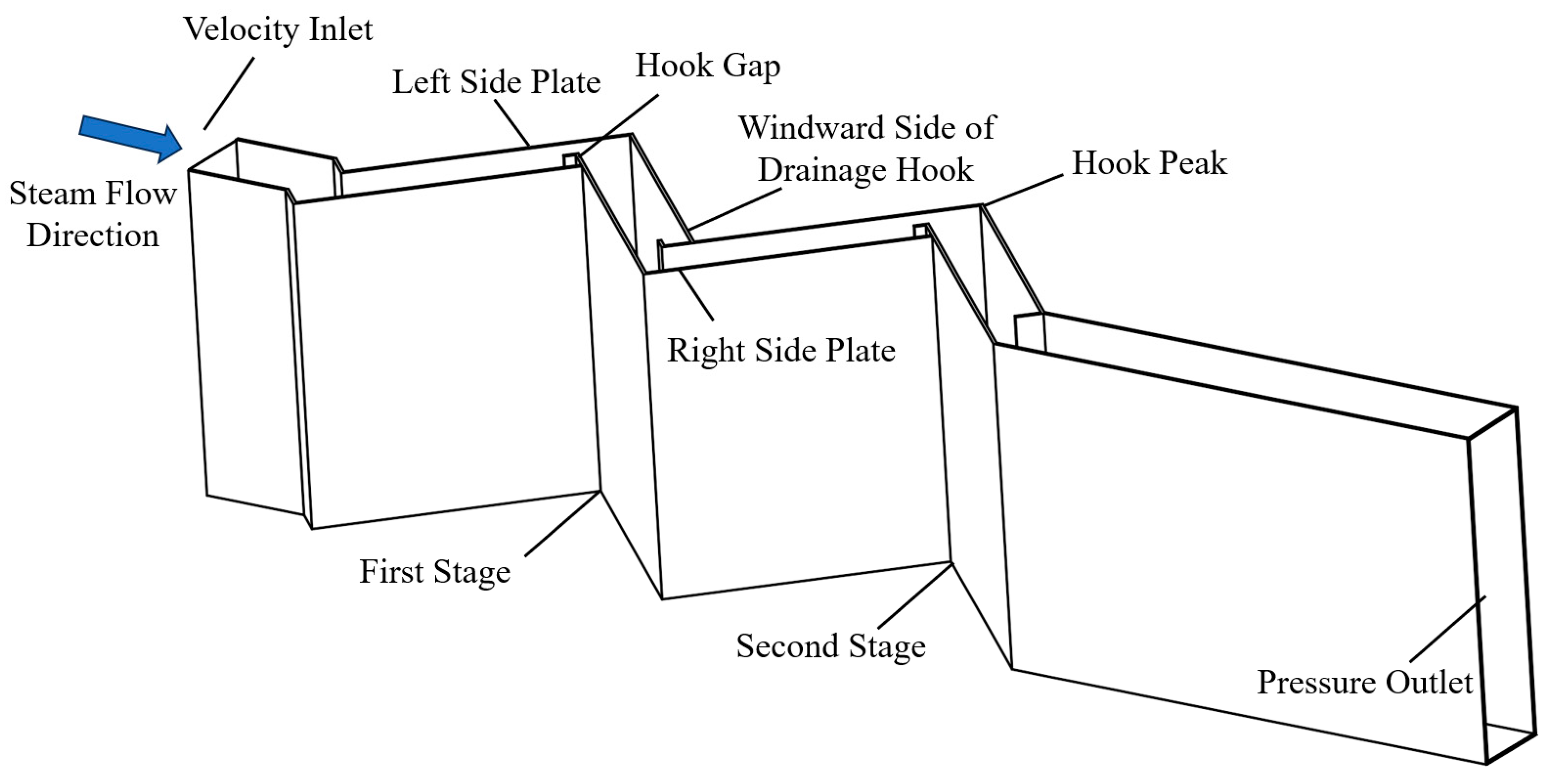
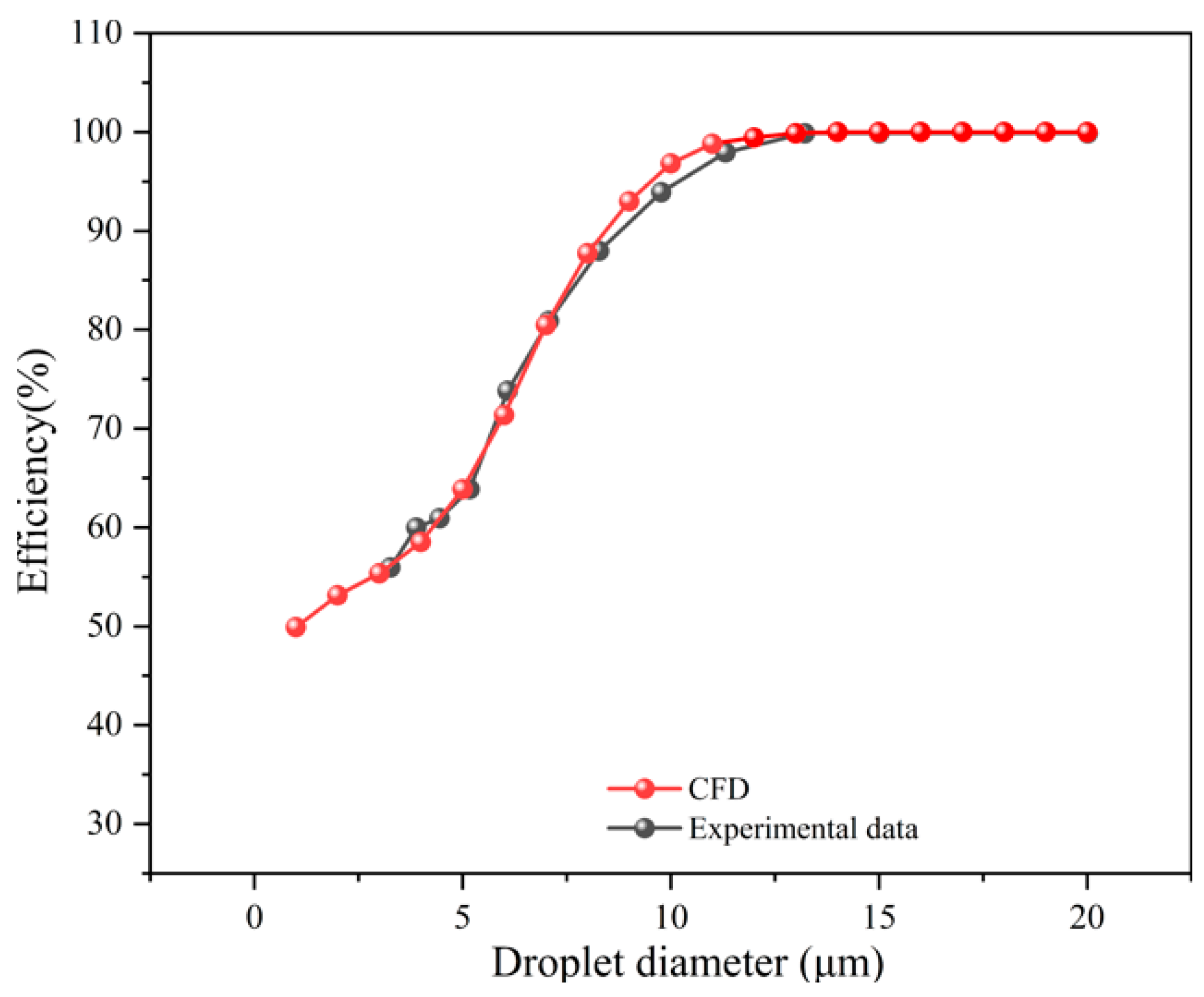
Based on the above background, this study proposes an integrated research framework for a hooked corrugated plate separator, incorporating high-fidelity CFD modeling, automated data generation, and data-driven optimization. First, a gas–liquid two-phase flow numerical model based on the Euler–Lagrange approach was established and validated against experimental data, with the results showing good agreement between the simulation and experimental results. Subsequently, an automated numerical simulation workflow was developed using Python 3.12 and PyFluent 0.38.1 to efficiently generate large-scale simulation datasets under multiple operating conditions. On this basis, an MLP surrogate model was constructed using inlet velocity, droplet diameter, and structural parameters as input variables, while separation efficiency and pressure drop were taken as output indicators. Multi-objective optimization was then performed using the NSGA-II algorithm. This study aims to improve structural optimization efficiency while maintaining the accuracy of numerical simulations, thereby providing an efficient and reliable data-driven approach for the engineering design of corrugated plate separators. The findings of this work are expected to support the development of high-efficiency and low-energy-consumption gas–liquid separation equipment, contributing to carbon neutrality goals in the global nuclear energy and process industries. In addition, the automated CFD–surrogate model–multi-objective optimization integrated framework developed in this study can reduce the time required for structural optimization analysis from several hours to only a few minutes, significantly improving engineering optimization efficiency.
3. Automated Numerical Simulation Method
3.1. Automated Workflow
The separation performance of corrugated plate separators is jointly influenced by multiple parameters, including inlet velocity, droplet diameter, plate spacing, and hook length. To systematically investigate the separation characteristics under different parameter combinations, a large number of numerical simulations are required. Traditional manual procedures—comprising geometry modeling, solution, and post-processing—are not only inefficient but also prone to human-induced errors during multi-condition switching, making it difficult to ensure dataset consistency.
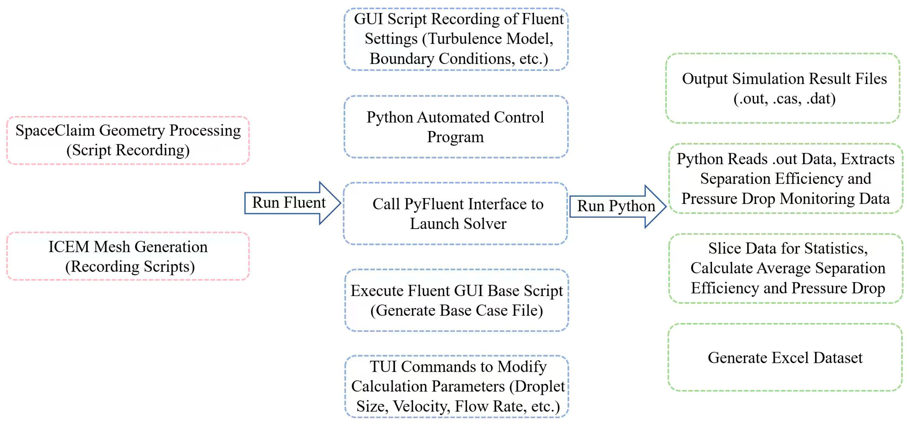
To address this issue, an automated numerical simulation framework for the corrugated plate separator was developed based on Python using the PyFluent interface. This framework enables full-process automation, including geometry modeling, mesh generation, solution control, and data extraction. The overall workflow is illustrated in
Figure 4.
During the preprocessing stage, batch operations are implemented by recording and executing system scripts of the relevant software. In the solution stage, the simulation process in Fluent is automatically controlled through a combination of GUI scripting, TUI commands, and API calls. In the post-processing stage, output data are parsed and organized using Python scripts, and structured datasets are generated in Excel format.
3.2. Automation of Geometry Preprocessing and Mesh Generation
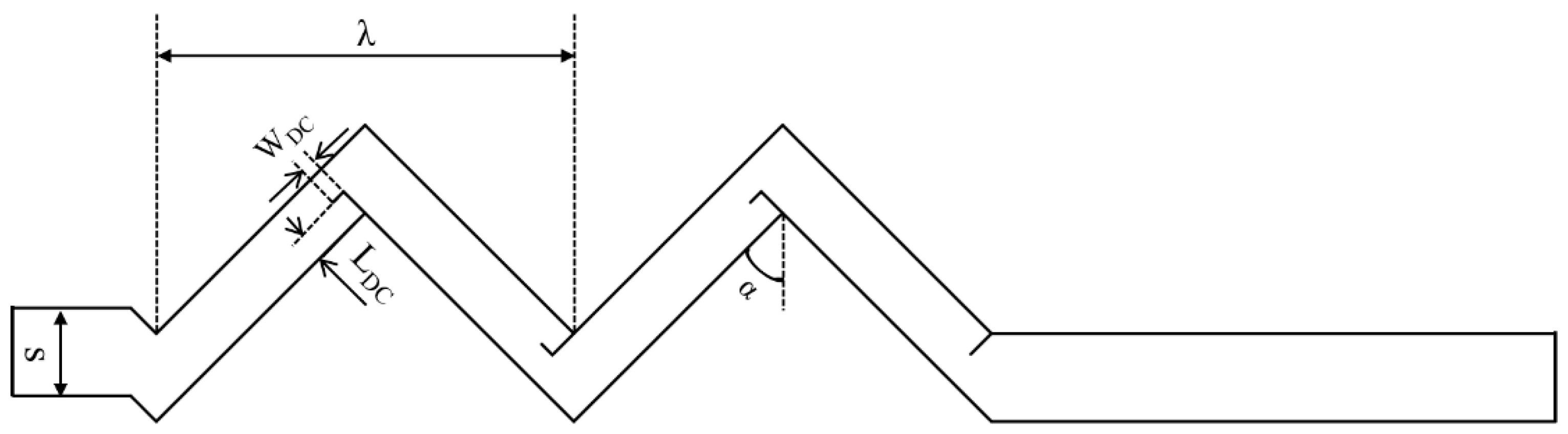
Automated batch construction of geometries is the primary step in the workflow. The baseline model is first created using CAD 2018 software. Geometric operation scripts are recorded in SpaceClaim to modify key parameters, including plate spacing (20–30 mm) and hook length (4.0–6.0 mm), and to extract the computational domain. In this way, repetitive geometry processing is transformed into reusable script files.
Mesh generation is automated using the Recording Scripts function in ICEM. After establishing a standard meshing strategy, the entire procedure is recorded and reused to ensure consistency and efficiency.
3.3. Solver Automation Based on a Hybrid Control Strategy
After preprocessing, the mesh is imported into ANSYS Fluent 2024 R1 for numerical simulation. Due to certain limitations of the PyFluent API in solver control and model configuration, a hybrid control strategy combining GUI scripts, TUI commands, and the Python API is adopted to achieve flexible and reliable automation.
A standard simulation setup is first completed in the Fluent GUI, including the solver type (pressure-based, transient), physical models (realizable k–ε turbulence model and discrete-phase model, DPM), boundary conditions (velocity inlet and pressure outlet), and solution control parameters (relaxation factors and convergence criteria). These operations are recorded as a journal file (*.jou), which serves as a template to ensure consistency and stability across all cases.
A Python-based control program is then developed to automate solver execution via the PyFluent interface. PyFluent provides APIs to load mesh files, execute journal scripts, issue TUI commands, and monitor solver status. For each case, the base journal file is loaded, and key parameters are dynamically modified using embedded TUI commands.
For example, inlet velocity and droplet diameter can be adjusted through TUI commands to define particle injection conditions at the inlet boundary, including particle size, initial velocity, and related parameters governing droplet motion. After parameter updates, the solver is executed automatically until convergence or a predefined iteration limit is reached.
3.4. Automated Extraction and Processing of Simulation Data
After each simulation, Fluent generates an output file (*.out) containing the complete history of separation efficiency and pressure drop. To address issues such as incomplete convergence and inefficiencies in manual data processing, a Python-based data parsing program is developed to batch-process all output files.
The monitoring data from the final 10–20% of iterations are extracted and averaged to ensure stable and representative results. This approach enables efficient, standardized, and accurate processing of large-scale simulation data.
4. Effects of Geometric and Operating Parameters on Separator Performance
4.1. Effect of Inlet Velocity
The inlet velocity is a key parameter affecting the performance of corrugated plate separators. Variations in velocity not only alter the internal flow field structure but also influence droplet inertia and their collision and capture behavior on the walls, thereby significantly affecting both separation efficiency and pressure drop.
In this section, inlet velocities of 1.0, 1.4, 1.8, 2.0, 2.4, 2.8, and 3.0 m/s are investigated under different plate spacings and hook lengths.
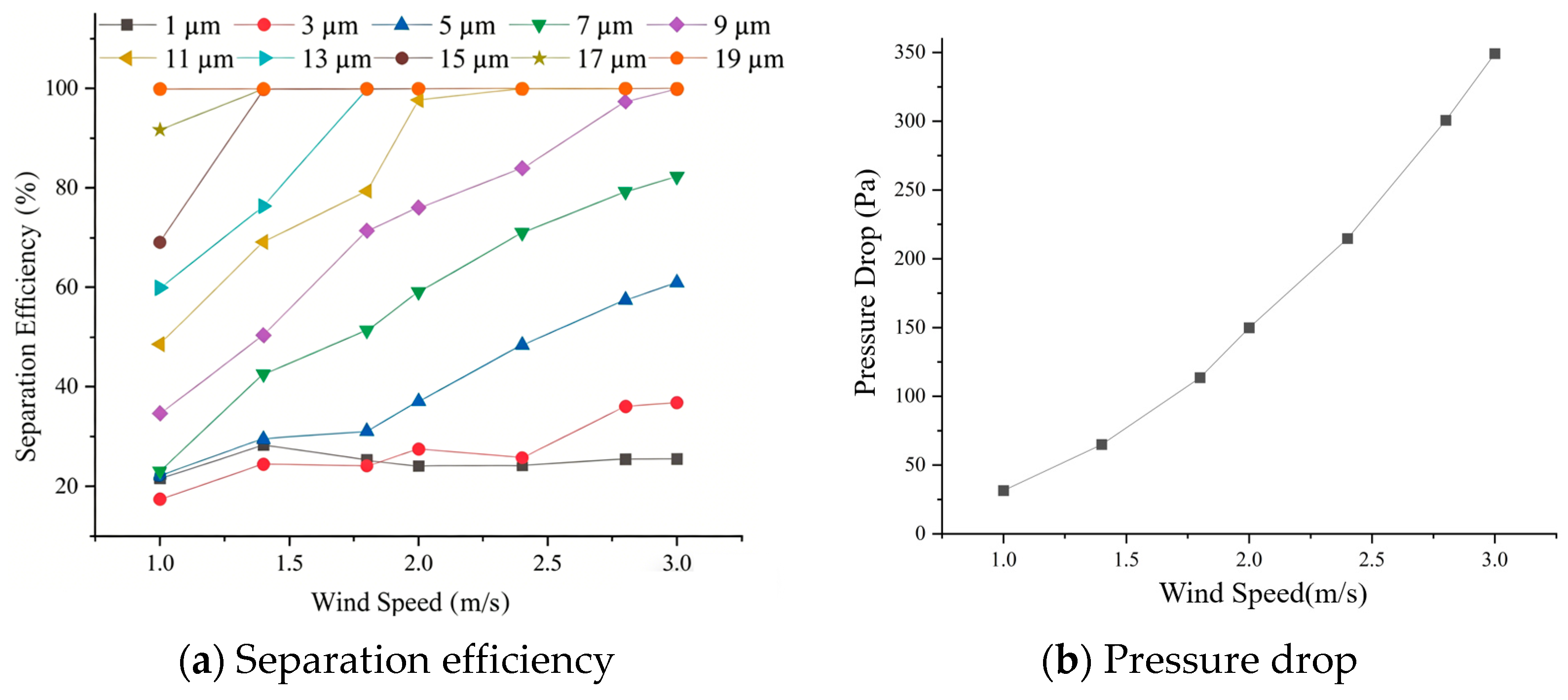
Under the conditions of a plate spacing of 25 mm and a hook length of 4.0 mm, the effects of inlet velocity on separator performance are shown in
Figure 5. The simulated droplet diameters range from 1 to 20 μm, while only selected sizes are presented for brevity.
Figure 5a illustrates the variation in separation efficiency with droplet diameter under different inlet velocities. It can be observed that increasing inlet velocity has negligible influence on the separation efficiency of 1 μm droplets and only a slight effect on 2 μm droplets. However, for droplets in the range of 3–9 μm, the separation efficiency increases significantly with velocity. When the droplet diameter reaches 11 μm, complete separation (100% efficiency) is achieved at an inlet velocity of 2.4 m/s. As the droplet size further increases, the critical velocity required for complete separation gradually decreases. For droplets of 19 μm, complete separation is achieved under all velocity conditions.
The influence of inlet velocity on pressure drop is shown in
Figure 5b. The pressure drop increases monotonically with increasing velocity, with a substantial growth rate. Specifically, as the inlet velocity increases from 1.0 m/s to 3.0 m/s, the pressure drop rises from 31.51 Pa to 349.23 Pa, corresponding to an overall increase of 317.72 Pa.
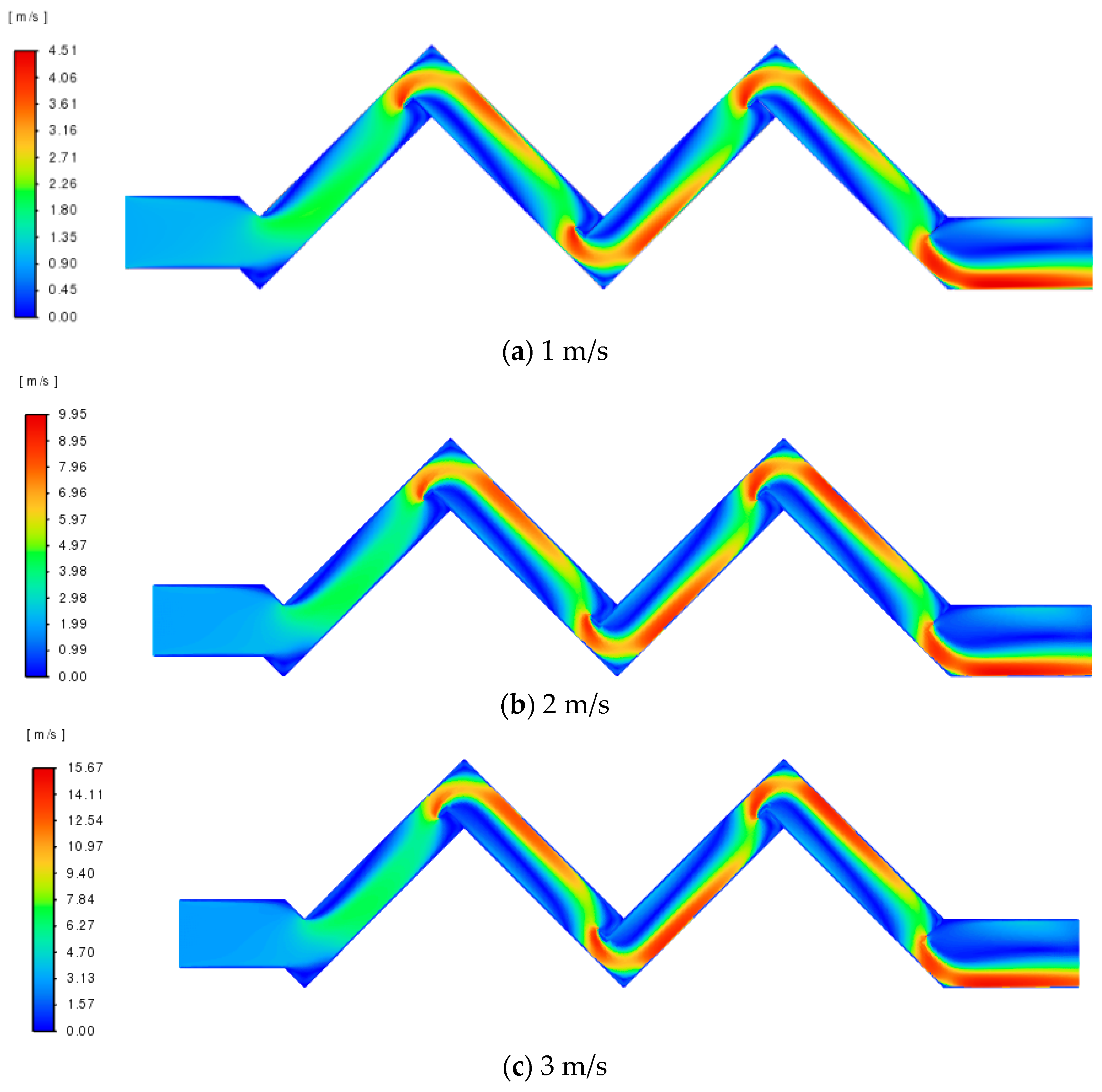
The flow field under different inlet velocities is shown in
Figure 6. The maximum velocities corresponding to inlet velocities of 1, 2, and 3 m/s are 4.51 m/s, 9.95 m/s, and 15.67 m/s, respectively. As the inlet velocity increases, the high-velocity regions (red zones) expand significantly within the flow field.
4.2. Effect of Droplet Diameter
In addition to inlet velocity, droplet diameter is another key factor affecting the performance of corrugated plate separators. The droplet diameter determines its inertia: larger droplets are more likely to deviate from the gas streamlines and collide with the plate surfaces, leading to effective capture, whereas smaller droplets tend to follow the flow and are more difficult to separate. In this section, droplet diameters ranging from 1 to 20 μm (20 sizes) are investigated.
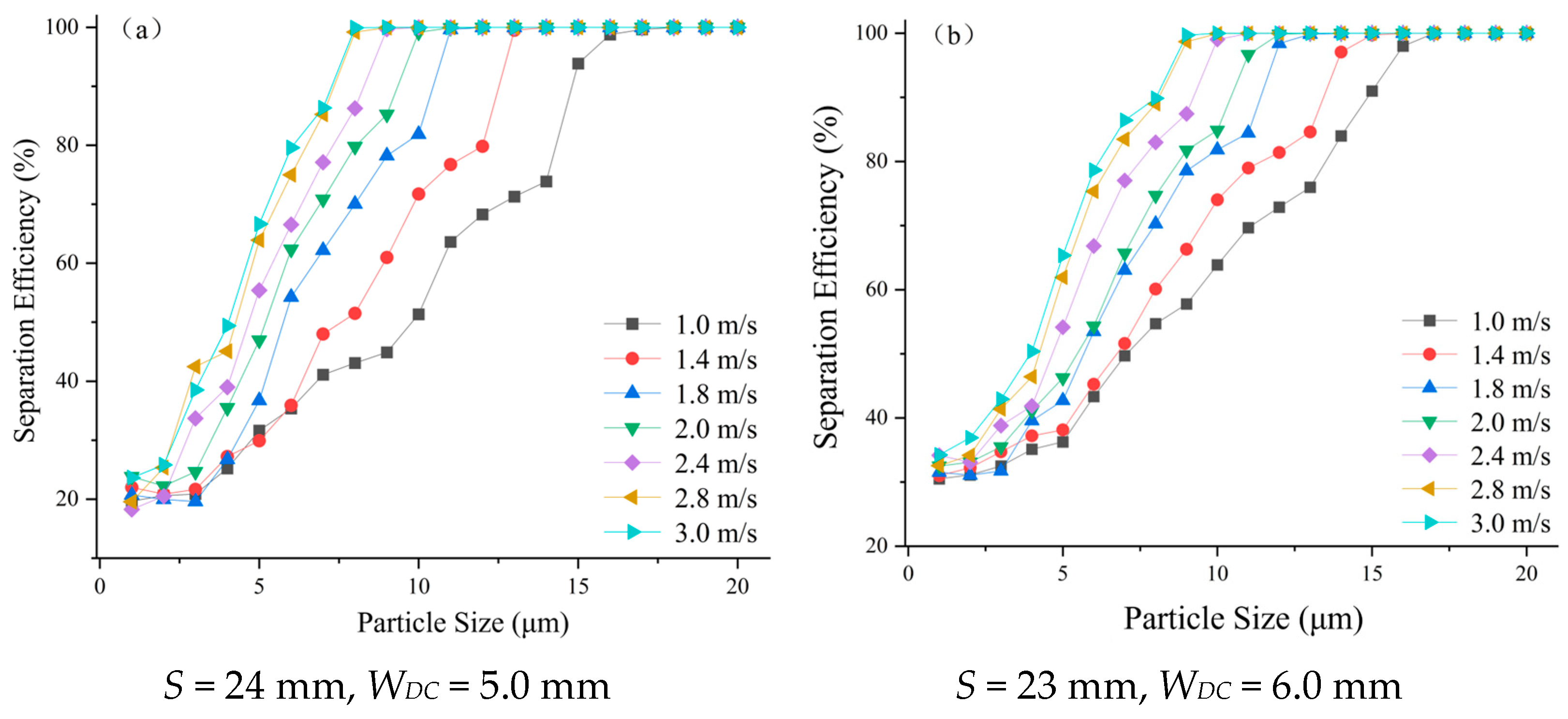
Under the conditions of a plate spacing of 24 mm and a hook length of 5.0 mm, the effect of droplet diameter on separator performance is shown in
Figure 7a. For a plate spacing of 23 mm and a hook length of 6.0 mm, the corresponding results are presented in
Figure 7b. Overall, separation efficiency increases with increasing droplet diameter. For a given droplet size, higher inlet velocity also leads to higher separation efficiency.
A comparison between
Figure 7a,b shows that reducing plate spacing and increasing hook length significantly enhance separation performance. Specifically, the separation efficiency in
Figure 7b is approximately 10% higher than that in
Figure 7a across the entire droplet size range. In addition, as the inlet velocity increases, the critical droplet diameter required to achieve 100% separation decreases, indicating that higher velocities promote the separation of smaller droplets.
Further analysis reveals that in
Figure 7a, when the inlet velocity ranges from 1.0 to 2.0 m/s and the droplet diameter is between 1 and 3 μm, the separation efficiency shows little variation among different velocities. In contrast, in
Figure 7b, this behavior extends to a wider range of 1–5 μm.
As discussed in
Section 2.3, under a given inlet velocity, the pressure drop remains nearly constant for droplet diameters ranging from 1 to 20 μm. Therefore, the variation in pressure drop is not presented in this section.
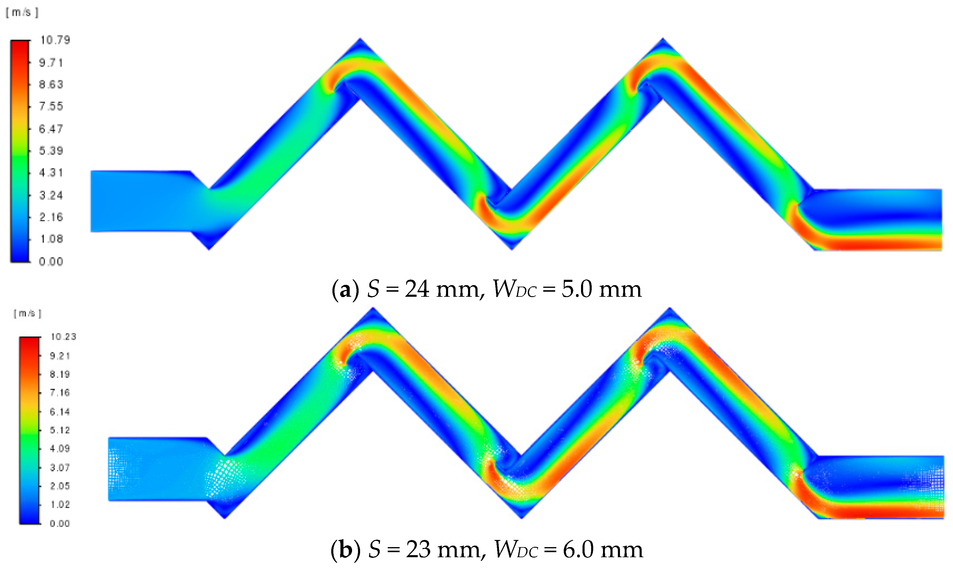
Figure 8a shows the velocity contours for a plate spacing of 24 mm and a hook length of 5.0 mm, while
Figure 8b corresponds to a plate spacing of 23 mm and a hook length of 6.0 mm. The maximum velocities reach 10.79 m/s and 10.23 m/s, respectively. For a given geometry and inlet velocity, the velocity contours are identical for all droplet sizes.
4.3. Effect of Plate Spacing
In the corrugated plate gas–liquid separator, the spacing between plates directly affects the collision and settling trajectories of droplets. The original spacing of the hook-type corrugated plates is S = 25 mm. To investigate the effect of plate spacing on the separation performance of the corrugated plate separator, S was varied to 21 mm, 22 mm, 23 mm, 24 mm, 26 mm, 27 mm, 28 mm, 29 mm, and 30 mm in the simulations.
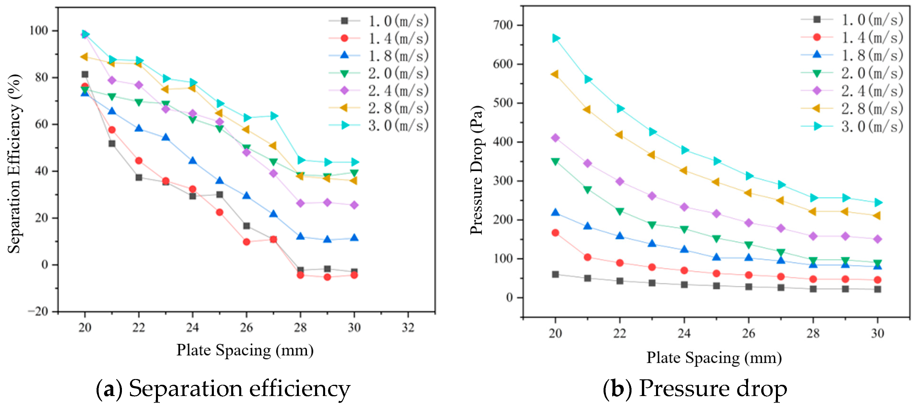
For a droplet diameter of 6 μm, the variation in separation efficiency with plate spacing under inlet velocities of 1.0, 1.4, 1.8, 2.0, 2.4, 2.8, and 3.0 m/s is shown in
Figure 9a, it can be observed that the separation efficiency generally decreases with increasing plate spacing and becomes nearly constant beyond 28 mm. In addition, higher inlet velocities lead to higher separation efficiency. When the inlet velocity is 1.0 and 1.4 m/s, negative separation efficiency occurs at plate spacings larger than 27 mm. This is mainly attributed to the insufficient inertia of small droplets, which are easily entrained by the gas flow and escape from the outlet without being effectively captured.
The effect of plate spacing on pressure drop is shown in
Figure 9b. The pressure drop increases with increasing inlet velocity. At an inlet velocity of 1.0 m/s, the pressure drop remains nearly constant with plate spacing. At higher velocities, the pressure drop decreases exponentially as plate spacing increases and gradually levels off at larger spacings.
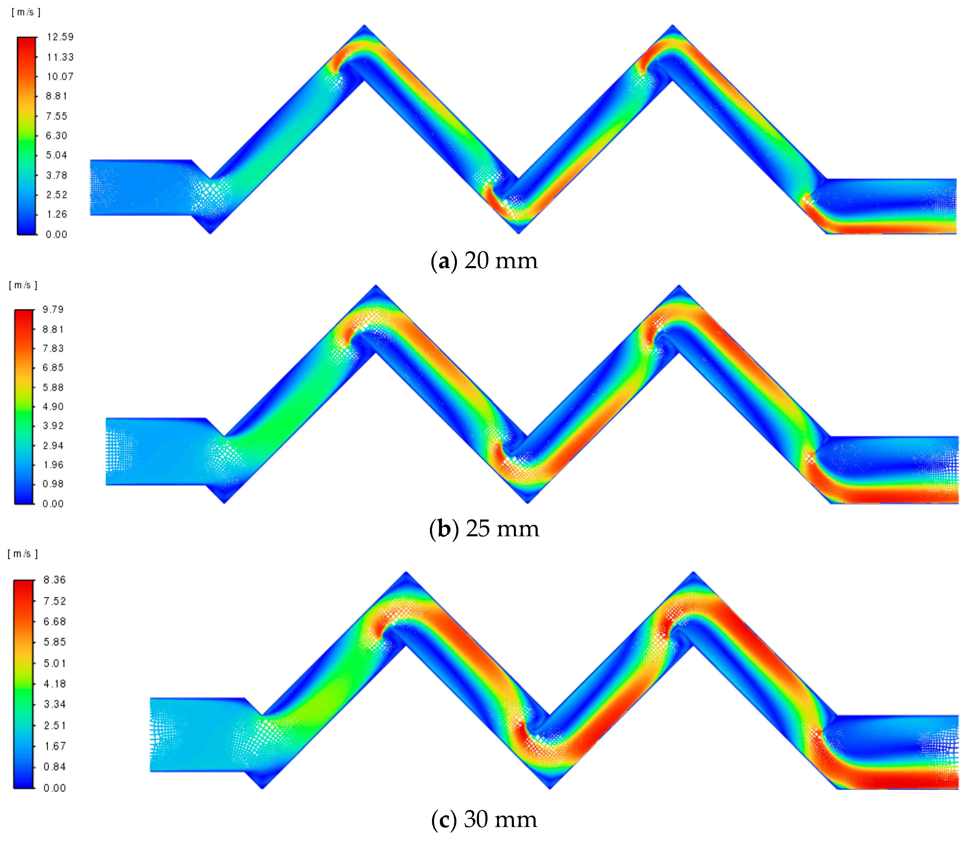
The velocity contours for different plate spacings are shown in
Figure 10, with representative cases of 20 mm, 25 mm, and 30 mm. The flow channel exhibits a typical wavy structure. In the hook region, the flow accelerates significantly, forming a high-velocity zone near the outer wall, while low-velocity regions appear near the inner side due to flow obstruction and recirculation.
The maximum velocity varies with plate spacing, reaching 12.59 m/s, 9.79 m/s, and 8.36 m/s for spacings of 20 mm, 25 mm, and 30 mm, respectively. This indicates that smaller plate spacing enhances flow acceleration due to channel constriction. As the spacing increases, the flow area expands and the high-velocity region becomes more widely distributed, as observed in
Figure 10c compared with
Figure 10a.
4.4. Effect of Hook Length
In the corrugated plate gas–liquid separator, the hook length determines the droplet capture capability and residence time on the plate surface, directly affecting the likelihood of droplet re-entrainment. The original hook length of the hook-type corrugated plates is WDC = 4.3 mm. To systematically investigate the effect of hook length on separation performance, numerical simulations were conducted for structures with hook lengths of 4.0, 4.3, 4.6, 4.8, 5.0, 5.2, 5.4, 5.6, 5.8, and 6.0 mm.
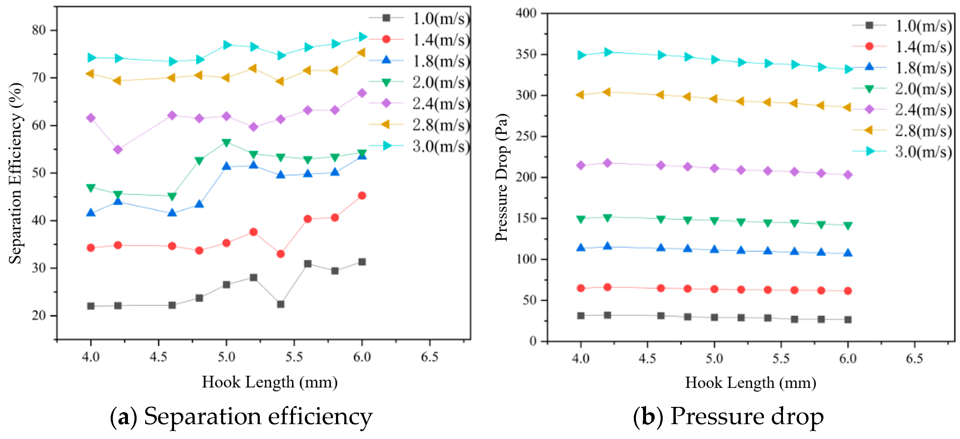
For a droplet diameter of 6 μm, the variation in separation efficiency with hook length under inlet velocities of 1.0–3.0 m/s is shown in
Figure 11a. Overall, the separation efficiency exhibits moderate fluctuations with increasing hook length, and the trends vary with inlet velocity. At low velocities (1.0 and 1.4 m/s), the efficiency shows a similar trend, with a noticeable decrease at a hook length of 5.4 mm, followed by recovery. At intermediate velocities (1.8 and 2.0 m/s), a slight increase is observed around 4.8 mm, followed by a decrease at 5.4 mm. At 2.4 m/s, the efficiency drops near 4.3 mm and then stabilizes. At higher velocities (2.8 and 3.0 m/s), the fluctuation becomes less pronounced, and the variation remains relatively smooth.
The effect of hook length on pressure drop is shown in
Figure 11b. The pressure drop increases with inlet velocity. Under the same velocity, it generally decreases slightly with increasing hook length. Moreover, this decreasing trend becomes more evident at higher velocities, indicating that the influence of hook length on pressure drop is more significant under high-velocity conditions.
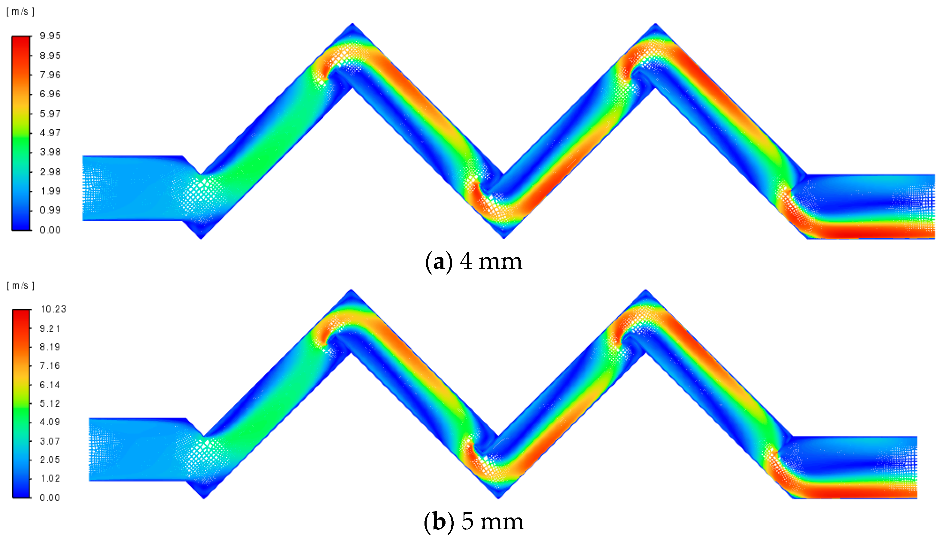
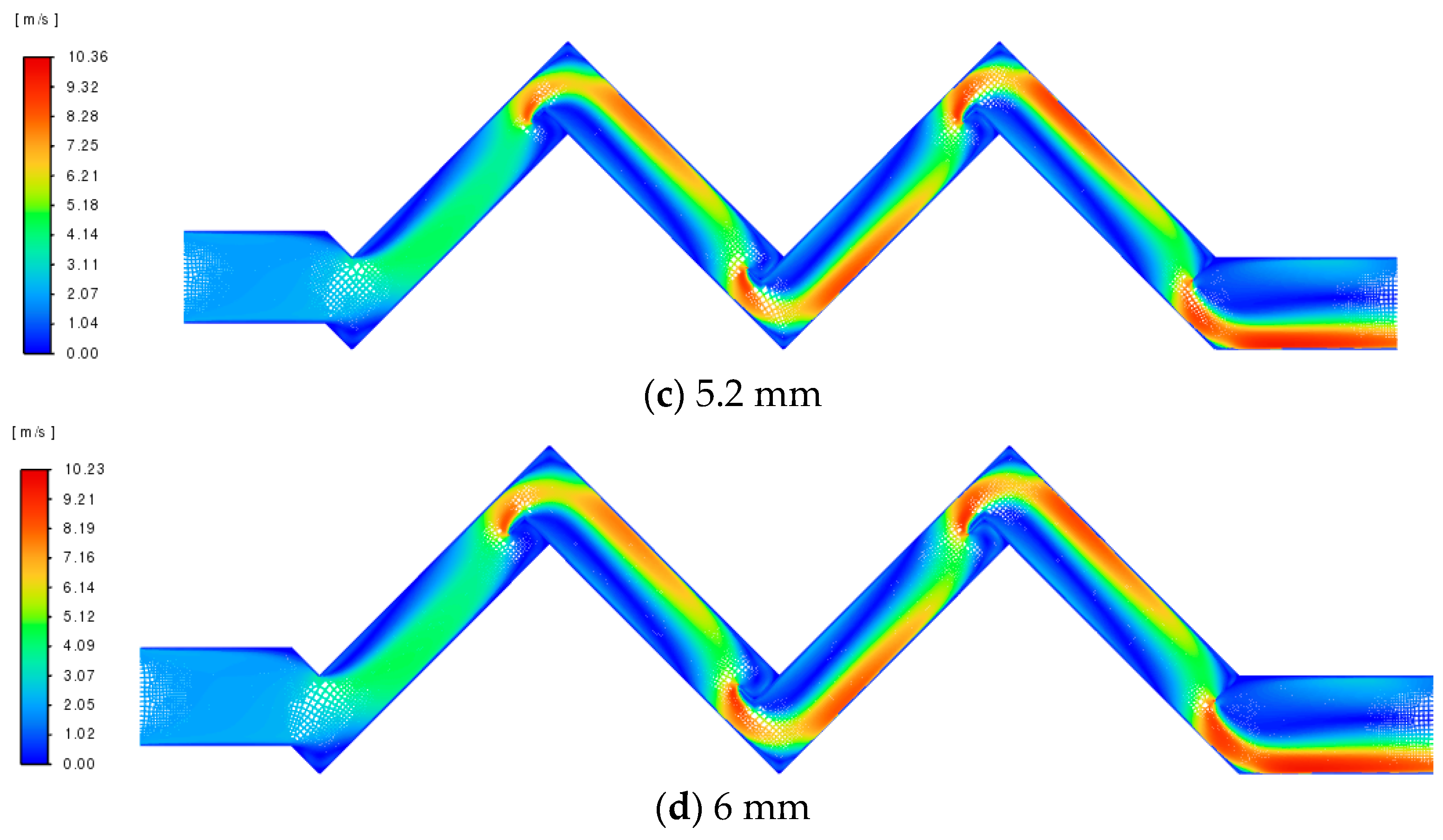
The velocity contours under different hook lengths are shown in
Figure 12. Due to space limitations, representative cases with hook lengths of 4.0 mm, 5.0 mm, 5.2 mm, and 6.0 mm are selected for comparison.
The results indicate that the lowest maximum velocity occurs at a hook length of 4.0 mm. When the hook length is 5.0 mm and 6.0 mm, the maximum velocity reaches 10.23 m/s, while a slightly higher value of 10.36 m/s is observed at 5.2 mm. Overall, the maximum velocity first increases and then decreases with increasing hook length.
5. Neural Network Training and Genetic Algorithm Optimization
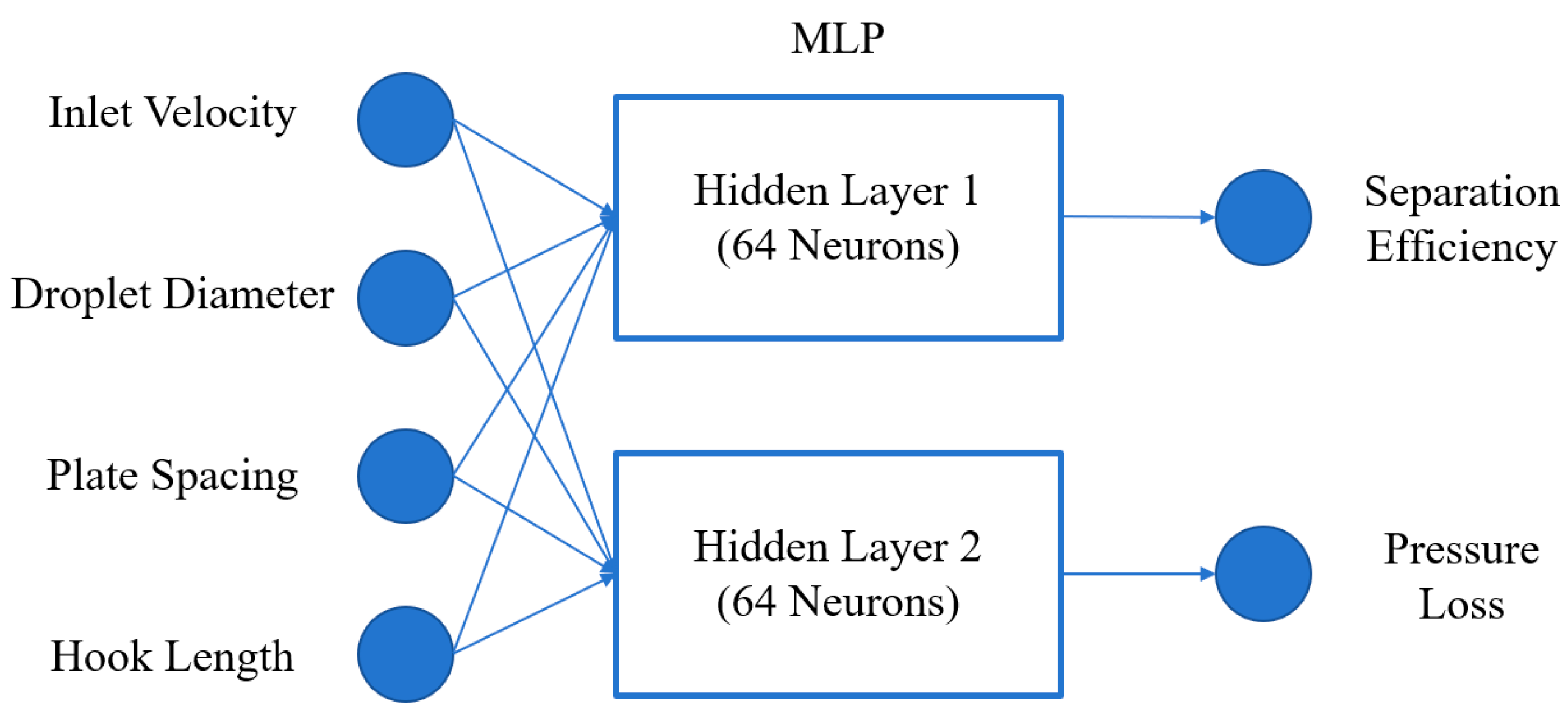
The inlet velocity, droplet diameter, plate spacing, and hook length are selected as input variables; therefore, the input layer consists of four neurons. The outputs of the model are separation efficiency and pressure drop, resulting in two neurons in the output layer.
Considering the strong nonlinearity of the flow field and droplet motion within the corrugated plate separator, a feedforward neural network with two hidden layers is adopted to improve the model’s capability in capturing complex relationships. Each hidden layer contains 64 neurons.
The Rectified Linear Unit (ReLU) activation function is employed in the hidden layers due to its advantages, including high computational efficiency, mitigation of gradient vanishing, and fast convergence, which contribute to improved training performance. The network architecture is illustrated in
Figure 13.
For the multi-output regression problem in this study, the Mean Squared Error (MSE) is adopted as the loss function to evaluate the prediction errors of separation efficiency and pressure drop. Model optimization is performed using the Adam algorithm, which combines momentum and adaptive learning rate mechanisms, offering fast convergence and high stability. The learning rate is set to 0.001, and the batch size is 64.
All numerical calculations and surrogate model training in this study were performed on a personal computer. The computational platform was equipped with a 13th Gen Intel® Core™ i5-13400F processor (2.50 GHz, Intel Corporation, Santa Clara, CA, USA), 32 GB of RAM, and an NVIDIA GeForce RTX 4060 graphics card (NVIDIA Corporation, Santa Clara, CA, USA), running a 64-bit operating system. Fluent 2025 R1 was employed. PyCharm 2023 was used as the primary development environment, and the MLP model was implemented, trained, and tested based on the PyTorch 2.1.0 deep learning framework.
During training, network weights are iteratively updated via backpropagation to minimize the loss function until convergence is achieved. To improve generalization capability, model performance is continuously monitored during training, and training strategies are adjusted accordingly. After training, the model is evaluated using a test set to verify its accuracy and reliability.
To construct a high-quality surrogate model, the key variables affecting the performance of the corrugated plate separator must be identified. Based on previous numerical analyses, inlet velocity, droplet diameter, plate spacing, and hook length significantly influence both separation efficiency and pressure drop, and are therefore selected as model input variables. The optimization objectives are set as maximizing separation efficiency and minimizing pressure drop.
The ranges of these parameters were determined by considering actual nuclear power separator operating conditions, typical structural sizes reported in the literature, numerical simulation stability, and surrogate model training requirements. Inlet velocity covers typical gas-phase conditions, droplet diameter encompasses the main scales of entrained droplets, and plate spacing and hook length are locally optimized from the original engineering design while ensuring manufacturability and flow stability. These four variables together define the design space
Table 1.
A two-stage data construction strategy is adopted in this study. First, single-factor analyses are conducted to obtain performance data under different plate spacings and hook lengths, resulting in 2940 samples. Based on this, to enhance the representation of multi-parameter coupling effects, a factorial-like expansion is performed by selecting representative parameter levels, including three inlet velocities, four plate spacings, and four hook lengths, generating an additional 960 multi-factor samples. In total, a dataset containing 3900 samples is constructed for surrogate model training and optimization.
To ensure reliability and generalization capability, the dataset is divided into training and test sets at a ratio of 80% and 20%, respectively. The training set is used for model learning, while the test set is used for performance evaluation, ensuring robust predictive capability under unseen conditions.
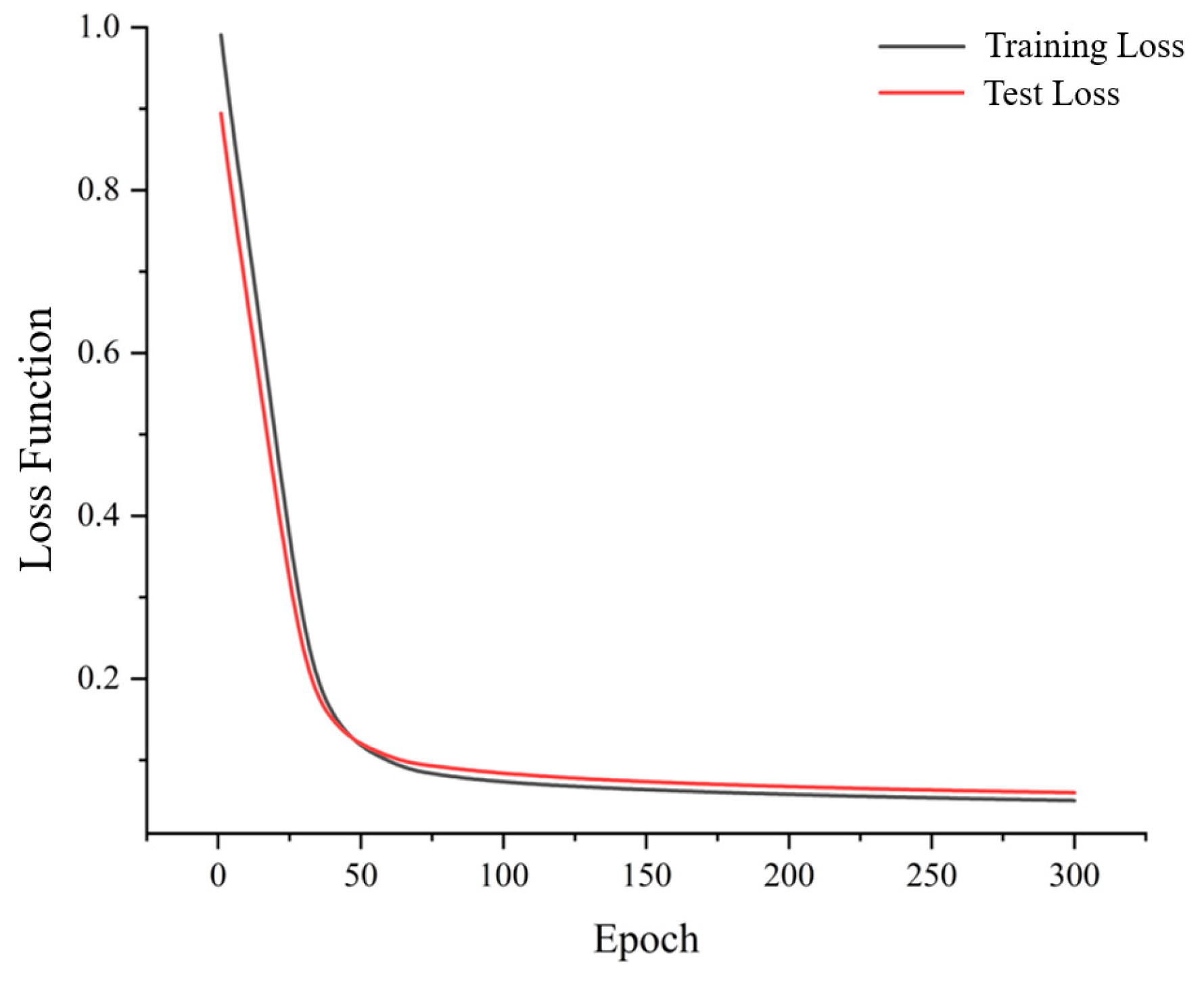
During training, both training and test losses decrease steadily with increasing epochs, as shown in
Figure 14, indicating stable convergence. No significant divergence is observed between the two curves, suggesting that overfitting is effectively avoided. In the early stage (first 50 epochs), the test loss is slightly lower than the training loss due to underfitting, where only general trends are captured. As training proceeds, the model gradually learns detailed features, and the test loss becomes slightly higher than the training loss and stabilizes, indicating adequate fitting. The optimal model is obtained at 300 epochs, achieving a balance between prediction accuracy and generalization.
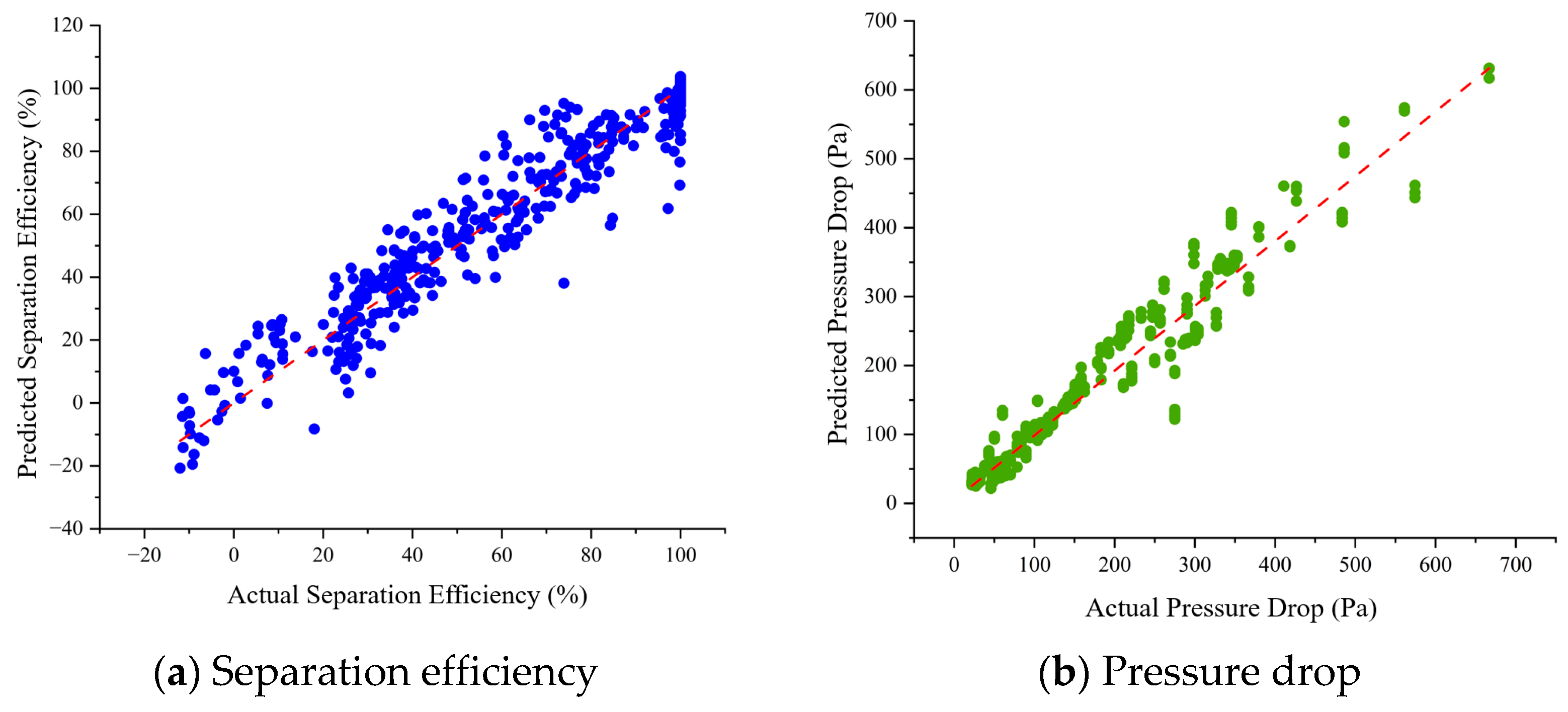
The prediction performance on the test set is presented in
Table 2 and
Figure 15. For separation efficiency, the model achieves an
of 0.95, indicating strong agreement with CFD results, with an RMSE of 10.23% and an MAE of 7.42%. For pressure drop, the model yields an
of 0.91, with an RMSE of 43.79 Pa and an MAE of 26.17 Pa, which are within acceptable engineering limits. These results demonstrate that the MLP model provides accurate and stable predictions for both objectives and can effectively replace computationally expensive CFD simulations for rapid performance evaluation.
After establishing and validating the surrogate model, a nonlinear mapping between design variables and performance metrics is obtained. However, the MLP model itself lacks optimization capability. Due to the inherent trade-off between separation efficiency and pressure drop, the problem is formulated as a multi-objective optimization task, whose solution is a set of Pareto-optimal solutions.
To address this, the NSGA-II algorithm is employed for multi-objective optimization, forming an integrated framework combining surrogate model prediction and evolutionary search. The surrogate model significantly improves computational efficiency, while NSGA-II ensures global search capability and solution diversity. Since the Pareto front contains multiple non-dominated solutions, the TOPSIS method is further applied for decision-making. Based on engineering requirements, weights of 0.7 and 0.3 are assigned to separation efficiency and pressure drop, respectively. The optimal solution is then identified by evaluating and ranking the closeness coefficients of the candidate solutions.
6. Numerical Results and Performance Analysis
Based on the Pareto-optimal solution set obtained from the MLP surrogate model and the NSGA-II algorithm, the optimal structural parameter combinations under different droplet diameters are identified using the TOPSIS method. The optimization results indicate that separation efficiency is significantly improved with only a limited increase in pressure drop, demonstrating that the proposed multi-objective optimization approach effectively balances performance enhancement and energy consumption.
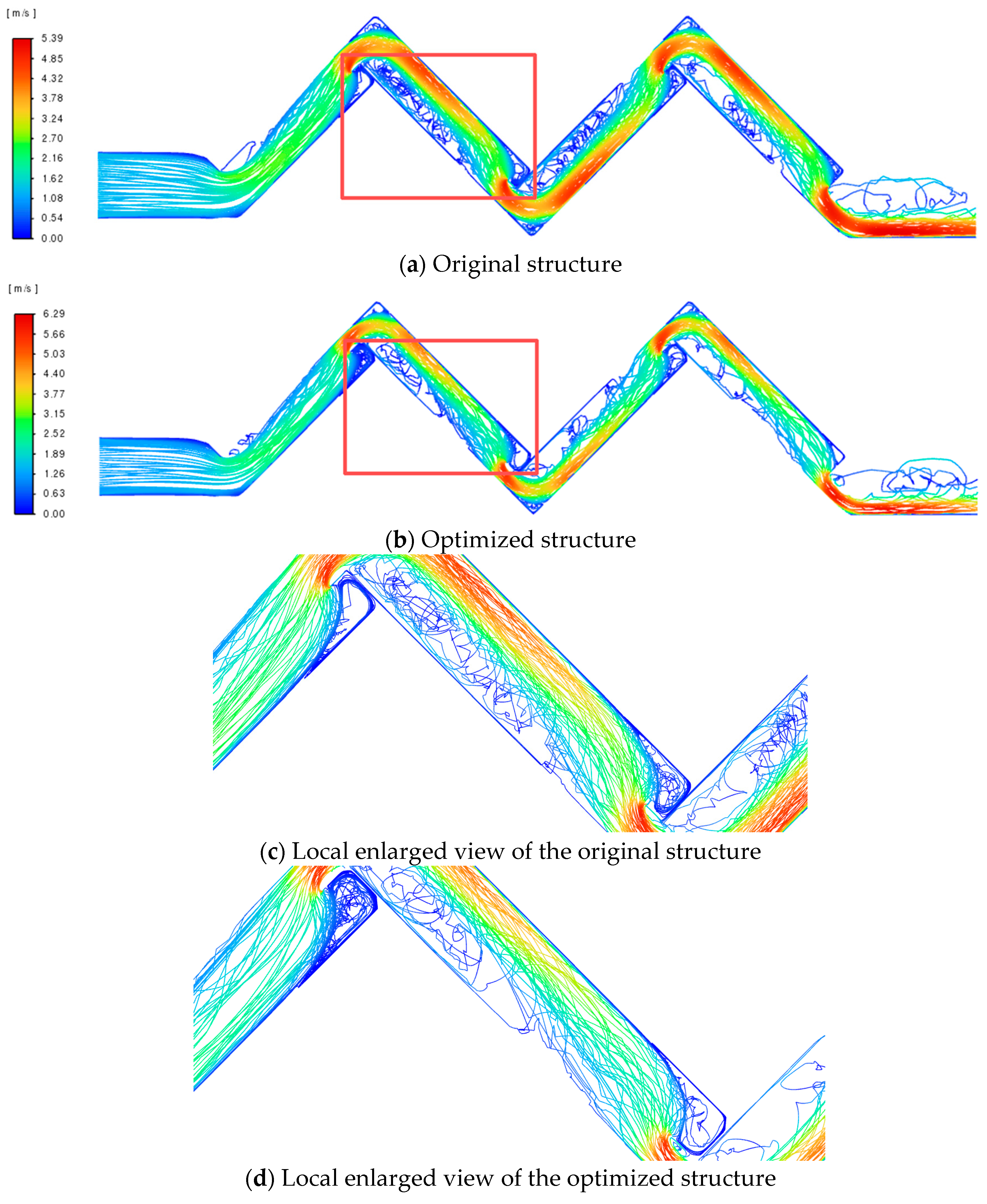
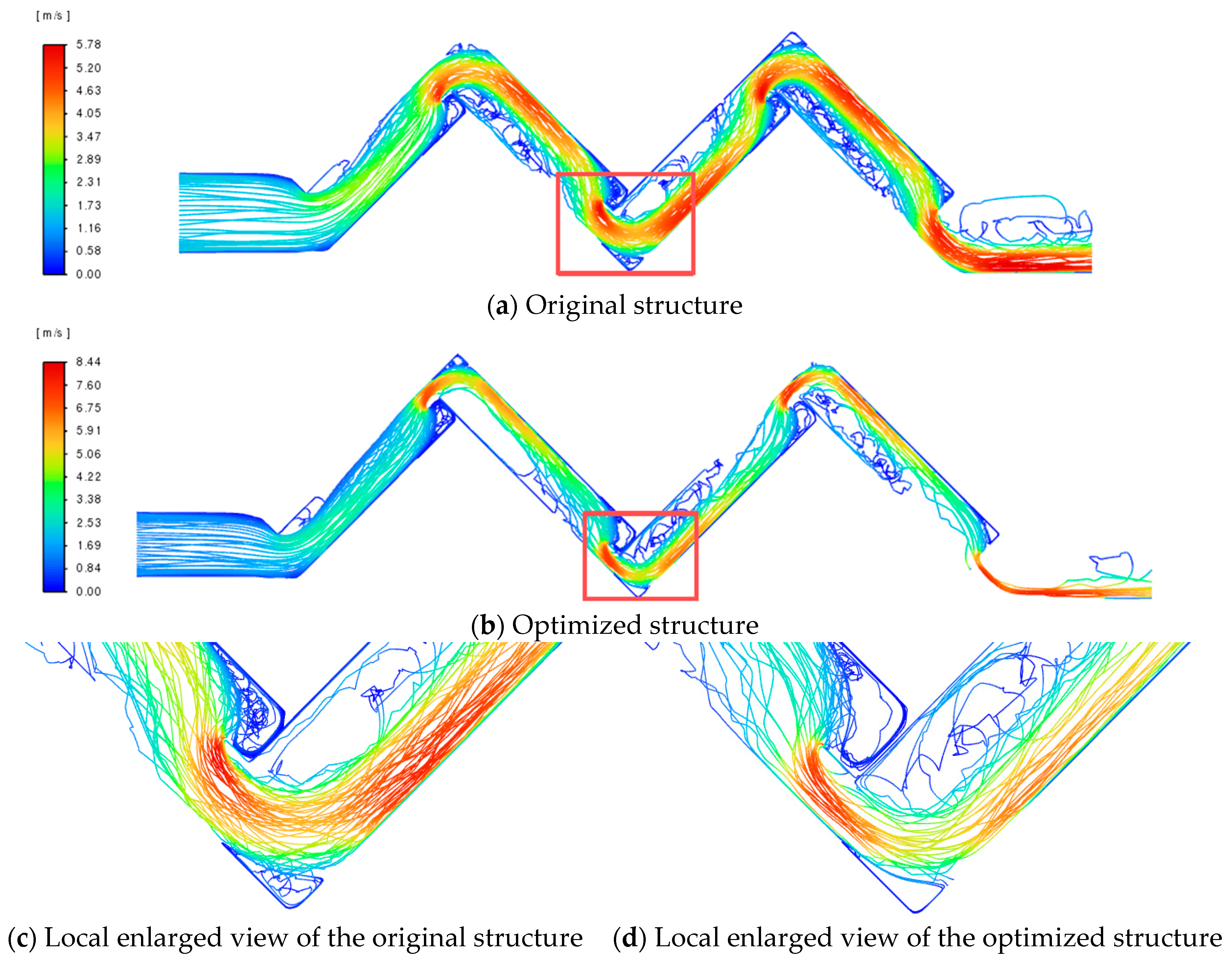
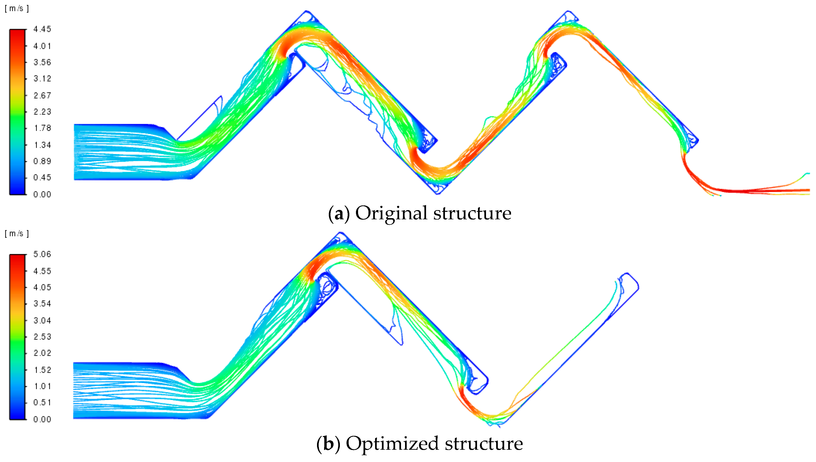
However, the above results mainly reflect macroscopic performance variations, while the underlying flow mechanisms require further investigation. Therefore, typical droplet diameters (5 μm, 10 μm, and 15 μm) are selected, and the corresponding optimized structures are compared with the original configuration. The performance enhancement mechanisms are analyzed from the perspectives of velocity field distribution and particle trajectories.
6.1. Optimal Structure for 5 μm Particle Size
According to the TOPSIS evaluation, the maximum closeness coefficient is 0.87, corresponding to an inlet velocity of
U = 1.18 m/s, a plate spacing of
S = 21.83 mm, and a hook length of
WDC = 5.92 mm. A comparison between the original and optimized structures is presented in
Table 3. At an inlet velocity of 1.18 m/s, the separation efficiency of the original structure is 26.62%, whereas the optimized structure achieves 55.76%, representing an improvement of 29.14% under the same conditions. In terms of pressure drop, the value increases from 45.22 Pa to 58.21 Pa, corresponding to an increment of 12.99 Pa.
The comparison of particle trajectories before and after optimization is shown in
Figure 16. As observed from
Figure 16a,b, the number of particle trajectories near the outlet is significantly reduced and becomes more sparsely distributed in the optimized structure, indicating a substantial decrease in droplet escape. This observation is consistent with the quantitative improvement in separation efficiency from 26.62% to 55.76%.
Figure 16c,d present enlarged views of the flow field. In the original structure, a large-scale recirculation vortex is formed near the first-stage hydrophobic hook, while the vortex in the second stage is relatively weak. In contrast, the optimized structure exhibits a weakened vortex in the first stage and a significantly strengthened vortex near the second-stage hook. This redistribution of vortex structures alters droplet migration paths, facilitating lateral deviation and promoting transport toward the wall.
Moreover, particle trajectories in the original structure are more dispersed and irregular, whereas in the optimized structure they become more concentrated and aligned with the main flow direction.
6.2. Optimal Structure for 10 μm Particle Size
According to the TOPSIS evaluation, the maximum closeness coefficient is 0.84, corresponding to an inlet velocity of
U = 1.34 m/s, a plate spacing of
S = 22.62 mm, and a hook length of
WDC = 5.78 mm. A comparison between the original and optimized structures is presented in
Table 4. At the same inlet velocity, the separation efficiency increases from 48.62% to 76.25%, representing an improvement of 27.63%. Meanwhile, the pressure drop rises from 64.05 Pa to 71.13 Pa, with an increment of 7.08 Pa. These results indicate that the optimized structure significantly enhances separation efficiency with only a slight increase in pressure drop.
The particle trajectories before and after optimization are shown in
Figure 17. Compared with the original structure, the optimized case exhibits fewer and more sparsely distributed trajectories near the outlet, indicating a substantial reduction in droplet escape.
Enlarged views in
Figure 17c,d reveal that droplets undergo significant directional deflection when passing through the hydrophobic hook region. In the optimized structure, droplet trajectories are more inclined toward the wall, suggesting an enhanced guiding effect of the flow field, which increases the probability of droplet–wall interactions.
Additionally, vortex structures are observed in the region enclosed by the hook and the upper wall in both configurations. However, the optimized structure exhibits larger and stronger vortices, which promote droplet entrainment into the near-wall region and facilitate deposition.
6.3. Optimal Structure for 15 μm Particle Size
According to the TOPSIS evaluation, the maximum closeness coefficient is 0.83, corresponding to an inlet velocity of
U = 1 m/s, a plate spacing of
S = 22.07 mm, and a hook length of
L = 6 mm. A comparison between the original and optimized structures is presented in
Table 5. At an inlet velocity of 1 m/s, the separation efficiency of the original structure is 74.29%, while the optimized structure achieves complete separation with an efficiency of 100%, representing an improvement of 25.71%. The pressure drop increases from 29.94 Pa to 39.80 Pa, indicating a relatively small increment of 9.86 Pa.
The comparison of particle trajectories before and after optimization is shown in
Figure 18. As observed from
Figure 18a,b, particle trajectories in the outlet region are significantly reduced after optimization, and in some channels, nearly no droplets pass through, indicating effective capture in the upstream region.
In terms of flow characteristics, droplets in the original structure exhibit relatively straight trajectories, with a certain fraction still penetrating through the downstream passages. In contrast, in the optimized structure, droplet trajectories are more strongly deflected toward the wall and become more concentrated, indicating enhanced inertial deviation and wall impingement.
7. Conclusions
Driven by global climate change and carbon reduction targets, improving the energy efficiency of key equipment in clean energy systems such as nuclear power has become an urgent priority. This study focuses on the structural optimization of a hooked corrugated plate moisture separator and develops an integrated framework combining automated CFD simulation, machine learning modeling, and multi-objective optimization. The effects of operating and geometric parameters on separation performance are systematically investigated, and optimal design solutions are obtained. The main conclusions are summarized as follows:
(1) An automated CFD platform based on Python and PyFluent is established, enabling full-process automation including geometry generation, meshing, solution control, and result extraction. A total of 3900 high-quality samples is obtained. Results show that increasing inlet velocity and droplet diameter improves separation efficiency but significantly increases pressure drop. Plate spacing exhibits an optimal range, where both excessively large and small values degrade performance. Increasing hook length enhances droplet capture, while excessive length leads to higher flow resistance. Flow field analysis indicates that the recirculation zone and shear layer near the hydrophobic hook are key regions governing droplet capture behavior.
(2) A multilayer perceptron (MLP) surrogate model is developed based on large-scale simulation data to accurately capture the nonlinear relationship between design variables and separation performance. The model achieves coefficients of determination (R2) of 0.95 for separation efficiency and 0.91 for pressure drop on the test set, demonstrating strong generalization capability and stability. Compared with traditional CFD simulations, the proposed model significantly reduces computational cost while enabling rapid performance prediction.
(3) A multi-objective optimization framework integrating the MLP surrogate model, NSGA-II algorithm, and TOPSIS decision-making method is established to achieve simultaneous optimization of separation efficiency and pressure drop. For 5 μm droplets, the optimal parameters are U = 1.18 m/s, S = 21.83 mm, and WDC = 5.92 mm, yielding a 29.14% increase in separation efficiency with a 28.7% increase in pressure drop. For 10 μm droplets, the efficiency improves by 27.63% with an 11.1% increase in pressure drop under U = 1.34 m/s, S = 22.62 mm, and WDC = 5.78 mm. For 15 μm droplets, the optimal configuration achieves complete separation with a 25.71% efficiency improvement and a 32.9% increase in pressure drop under U = 1.0 m/s, S = 22.7 mm, and WDC = 6 mm.
In summary, the proposed data-driven optimization method effectively controls the increase in pressure drop while maintaining or improving separation performance, thereby reducing the energy consumption of auxiliary systems in nuclear power plants and contributing to lower carbon emissions during operation. This study provides new research ideas and technical support for the low-carbon optimization design of complex gas–liquid separation devices, and offers positive engineering application value for advancing the global carbon neutrality goals in nuclear and process industries.