Article

Enhanced AVR System Performance via Optimal PID Controller Design Using the Red-Tailed Hawk Algorithm


1
Department of Electrical Engineering, University of Ferhat Abbas Sétif-1, Setif 19000, Algeria
2
Department of Electrical Engineering, Faculty of Applied Science, University of Bouira, Bouira 10000, Algeria
3
Department of Electrical Power Systems, National University of Science and Technology Politehnica Bucharest—UNSTPB, 060042 Bucharest, Romania
*
Author to whom correspondence should be addressed.
Processes 2026, 14(10), 1550; https://doi.org/10.3390/pr14101550
Submission received: 3 April 2026 / Revised: 5 May 2026 / Accepted: 9 May 2026 / Published: 11 May 2026

Abstract

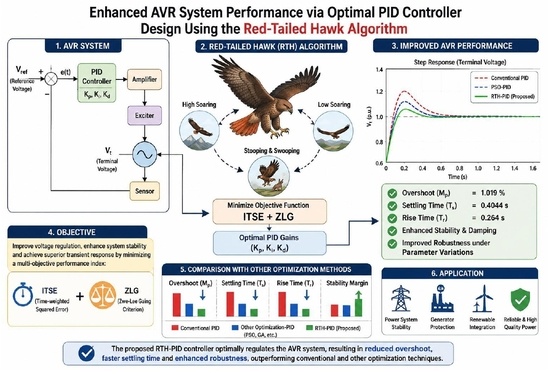
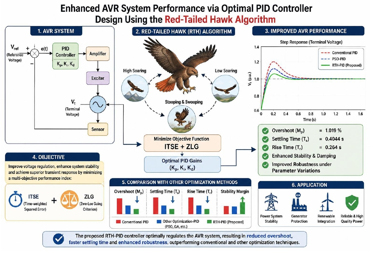
The stability and dynamic performance of power systems can be significantly improved by regulating the terminal voltage of synchronous generators using an automatic voltage regulator (AVR). However, the effectiveness of the AVR largely depends on the optimal tuning of the proportional integral derivative (PID) controller parameters. In this paper, a recently developed metaheuristic optimization technique, namely, the red-tailed hawk (RTH) algorithm, is employed to determine the optimal PID controller parameters for the AVR system. This proposed algorithm aims to minimize a multi-objective performance index that combines the time-weighted squared error (ITSE) and Zwe-Lee Gaing (ZLG) criterion, in order to improve voltage regulation performance, enhance system stability, and achieve superior transient response characteristics. The effectiveness of the proposed RTH-PID controller is validated through extensive simulations and comparative analyses with several well-established optimization PID tuning methods under the same constraints. The obtained results demonstrate that the proposed controller significantly improves dynamic performance by reducing overshoot, settling time, and rise time and enhancing system robustness. These findings confirm the superiority and reliability of the RTH-PID controller for AVR systems.

Graphical Abstract

1. Introduction

Delivering high-quality electricity to end consumers while keeping the terminal voltage within allowable bounds is a major difficulty in power systems. Operators must continuously monitor all loads and manage the output of various generation and storage sources. At all times, the voltage level must remain within predefined standards to ensure proper power quality. If these conditions are not maintained, the system can become unstable, leading to imbalances in active and reactive power. This may reduce generator efficiency and negatively affect equipment, machinery, and other utilities that rely on a stable power supply. Such issues often arise when voltage cannot be properly controlled, causing it to drop as demand increases.
Therefore, maintaining voltage stability within specified limits is essential across all levels of the power system. To achieve this, different control and regulation techniques are applied at various stages of operation. The AVR system has garnered a lot of attention lately as a crucial control loop that modifies the exciter voltage to regulate generator voltage at the required level. One such method is an AVR, which is crucial for regulating the output voltage of a generator or alternator in a power plant [1,2]. Thus, your generator’s longevity, efficiency, and the dependability of the gadgets it powers are all greatly influenced by the AVR. The AVR ensures the longevity and optimal operation of appliances, machinery, gadgets, and equipment by protecting them from potential damage by maintaining a constant voltage output despite any underlying fluctuations [3,4]. Therefore, a variety of controllers have been presented for managing AVR systems in order to achieve consistent performance and improve evaluation parameters. Numerous research studies have investigated various controller types, such as PID classical controllers, to handle terminal voltage regulation difficulties. Although these controllers may handle some stability problems, they frequently fail to solve problems caused by nonlinear loads, fluctuating operating conditions, and time delays [5]. By adjusting controller parameters, optimization techniques are used to address these problems and enable more efficient management of the complexity of the system. Artificial intelligence techniques, such as neural networks, fuzzy logic, and neuro-fuzzy systems, have been widely employed for optimizing controller parameters. However, they frequently face disadvantages, including long convergence times and the difficulty of analysis. Because of their simplicity, independence from gradient information, and reliance on simple notions, metaheuristic optimization algorithms have been popular in recent years for adjusting controller parameters. Usually, these techniques are categorized into the following: particle swarm optimization (PSO), which is a swarm-based approach, and genetic approach (GA) [6,7] The most significant class of physics-based algorithms includes the sine–cosine algorithm (SCA) [8], artificial bee colony (ABC) [9], improved kidney-inspired algorithm (IKA) [10], local unimodal sampling (LUS) [11], symbiosis organism search optimization algorithm (SOS) [12], gravitational search algorithm (GSA) [13], and biogeography-based optimization (BBO) [14]. Dung beetle optimizer (DBO) [15], load frequency control (LFC), and AVR in multi-area linked power systems, a unique hybrid control approach that combines a fuzzy proportional–integral–derivative double derivative (FPIDD2) controller with a traditional PID controller is provided in [16]. Teaching learned-based optimization (TLBO) [17], Q-learning algorithm [18], harmony search algorithm (HSA) [19], and PID-based search algorithm (PSA) [20] are examples of human-based algorithms. A hybrid genetic algorithm and particle swarm optimization algorithm (GA-PSO), which contains several parameters to solve any kind of problem because of the defined parameters, is proposed in [21]. Stochastic fractal search (SFS), a potent optimization technique with improved accuracy and shorter convergence times, was applied for the first time in the literature in [22]. However, in order to improve dynamic response and control accuracy, the authors of [23] developed a sigmoid-based PID (SPID) controller for the AVR system using an enhanced self-tuning heuristic optimization method called the nonlinear sine-cosine algorithm (NSCA). In contrast, [24] uses the recently developed symbiotic organisms search (SOS) method to try to tackle the issue of effective PID controller design applied to a common automated voltage regulator (AVR) system. The salp swarm algorithm (SSA), an innovative artificial intelligence-based optimization technique, is used in [25] to find the ideal PID for the AVR system. The SSA approach outperforms both the Ziegler–Nichols (ZN) and the artificial bee colony (ABC) tuning algorithms in enhancing the step response of an AVR system due to its simplicity and transient response analysis. Ref. [26] suggests a technique based on an improved PSO known as ADIWACO PSO for adjusting PID controllers for AVR systems. With ITAE as the objective function, this approach dynamically modifies exploration and exploitation parameters using hyperbolic tangent functions. When compared to BAT, KIA, ARO, and BBO algorithms, the results demonstrate a notable decrease in overshoot and settling time. A new PID controller for AVR systems based on the superb fairy-wren optimization algorithm (SFOA) is presented in [27]. When compared to current techniques, the suggested controller provides outstanding transient performance for the overshoot value, rising time, settling time, and steady-state error. The findings show that SFOA-based PID control is a viable and efficient substitute for voltage regulation in power systems. Ref. [28] presents a novel G-PID controller for AVR systems that embeds the Gudermannian function’s nonlinear mapping into the conventional PID structure to enhance adaptability and eliminate overshoot. Optimized by the starfish optimization algorithm (SFOA), the proposed controller achieves exceptional transient performance, outperforming standard algorithms like PSO and GWO as well as advanced fractional-order PID designs. For the automatic voltage regulator (AVR) to modify the terminal voltage, a number of techniques based on artificial intelligence and metaheuristic algorithms have generally been suggested and put into practice in the literature. The red-tailed hawk algorithm (RTH), a novel nature-inspired metaheuristic optimization method that optimizes PID parameters for the AVR system in terms of high efficiency, is proposed in this paper [29,30]. The core idea of this proposed optimizer is based on the hunting prowess of red-tailed hawks, which are known for their intelligence among raptors. To exceed the current optimization methods, the RTH algorithm incorporates the advantages of evolutionary and swarm methodologies. Other than that, this paper’s primary contribution is the proposal of a novel metaheuristic optimization algorithm inspired by nature for improved PID tuning parameters and optimization problems. In particular, these methods often suffer from premature convergence, inadequate balance between exploration and exploitation, and performance degradation when dealing with nonlinear and highly dynamic systems such as AVR. The key research gap addressed in this work is the absence of a robust optimization approach capable of maintaining population diversity while ensuring fast and stable convergence toward the global optimum in PID parameter tuning. By adding an adaptive parameter control mechanism that does away with manual tuning and a rank-based update strategy that prevents premature convergence, the RTH algorithm improves upon current metaheuristic-based PID tuning techniques. RTH outperforms HSA, IKA, SOS, and BBO in terms of objective function values and transient responsiveness (1.019% overshoot, 0.4044 s settling time). These findings show that RTH is a significant improvement for AVR-PID optimization rather than just a small addition.
Finally, the remainder of this work is structured as follows. A section of linked works that illustrates and describes a collection of related works is presented in Section 1. Section 2 of this paper provides a detailed description of an AVR system. The AVR transfer function model, the PID controller, and the suggested RTH controller model are then thoroughly discussed in Section 3. In Section 4, the suggested self-tuning RTH method is carefully examined. Section 5 presents the outcomes that were achieved. Lastly, Section 6 presents the findings reached.

2. PID-Based AVR System Design

2.1. AVR System Model Without PID Controller

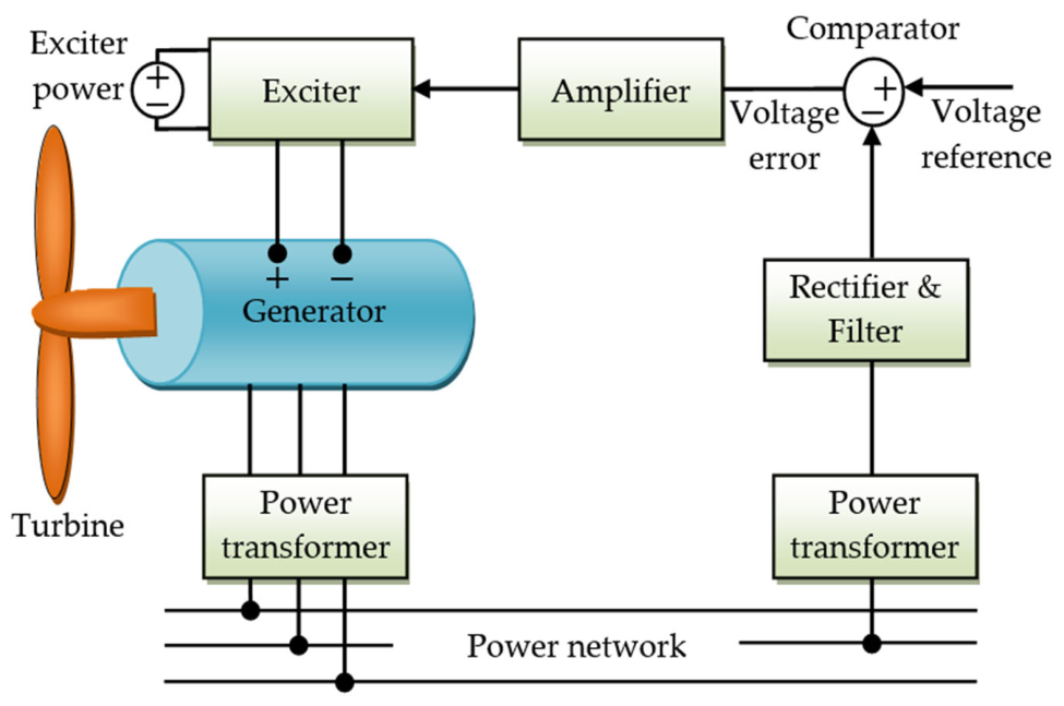
It is essential to keep voltage stability within predetermined bounds at all power system levels. To maintain this stability, voltage management techniques are used at various phases. Using an AVR to control the output voltage of a generator or alternator in a power plant is one such technique (Figure 1).
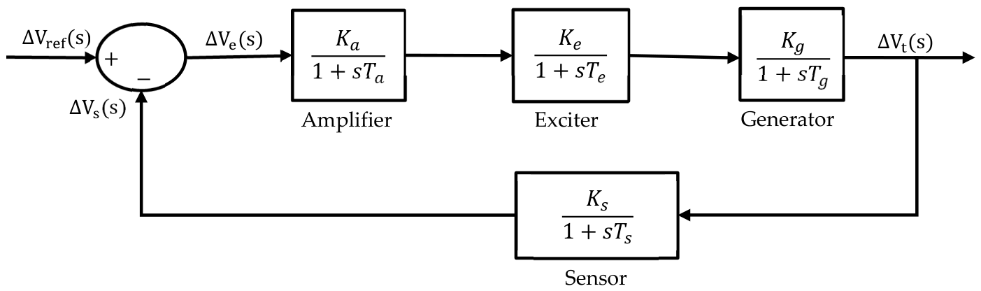
However, in addition to regulating voltages to acceptable levels, an AVR system offers defense against electrical surges, spikes, and generator overloads. Furthermore, as mentioned earlier, automatic voltage regulators (AVRs) are essential for allowing generators to appropriately distribute the reactive load among parallel-running generators, prevent short circuits, and manage overloads [30,31]. Figure 2 illustrates the transfer function model of the automatic voltage regulator (AVR) system, excluding the controller. This simplified representation encapsulates the fundamental dynamic behavior of key AVR components: the amplifier, exciter, generator, and sensor. In essence, Figure 3 shows the configuration of the AVR system’s parts. An AVR begins as a feedback control system by continuously measuring the terminal voltage Vt(s) of the generator and comparing it to the desired reference voltage Vref(s). The generator is excited using the exciter after the amplifier amplifies the error signal obtained from the difference between the reference voltage and the measured terminal voltage, Ve(s).
Figure 3 essentially depicts how the AVR system’s components are arranged. As a feedback control system, an AVR starts by continually sensing the generator’s terminal voltage Vt(s) and comparing it to the intended reference voltage Vref(s). The generator is excited using the exciter after the amplifier amplifies the difference between the reference and the detected terminal voltages (error voltage Ve(s)).
  • Amplifier model transfer
The amplifier is represented by a transfer function characterized by a gain Ka and a time constant Ta, expressed as follows:
T F A = K a 1 + s T a
The amplifier gain Ka typically ranges from 10 to 40, while the amplifier time constant Ta is relatively small, generally ranging from 0.02 to 0.1 s.
  • Exciter model
The exciter is represented by a transfer function characterized by a gain Ke and a time constant of Te, expressed as follows:
T F E = K e 1 + s T e
The exciter gain Ke typically ranges from 1 to 10, while the exciter time constant Te ranges from 0.4 to 1.0 s.
  • Generator model
The generator is represented by a transfer function characterized by a gain Kg and a time constant of Tg, expressed as follows:
T F G = K g 1 + s T g
The generator gain and time constant are load-dependent parameters. The gain typically varies between 0.7 and 1.0, while the time constant ranges from 1.0 to 2.0 s.
  • Sensor model
The sensor is commonly modeled as a first-order transfer function defined by a gain Ks and time constant Ts, expressed as follows:
T F S = K s 1 + s T s
The amplifier gain Ks typically ranges from 1 to 1, while the amplifier time constant Ts is relatively small, generally ranging from 0.001 to 0.06 s
The AVR system parameters are listed in Table 1 Based on these parameters, the transfer function of the system, excluding the PID controller, is expressed as:
Δ V t ( s ) Δ V r e f ( s ) = 0.1 s + 10 0.0004 s 4 + 0.0454 s 3 + 0.555 s 2 + 1.51 s + 11
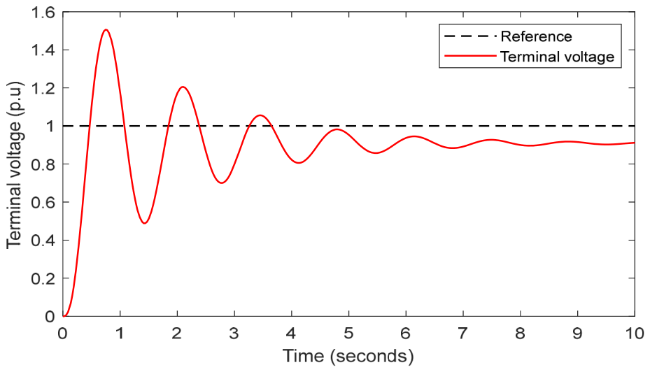
Figure 3 depicts the step response of the AVR system. The response is characterized by a 50% maximum overshoot, a rise time of 0.2620 s, a settling time of 7.0189 s, and a steady-state error (Ess) of 0.0881. Such characteristics highlight significant overshoot and oscillatory behavior, indicating unsatisfactory transient performance.

2.2. AVR System Model Based on PID Controller

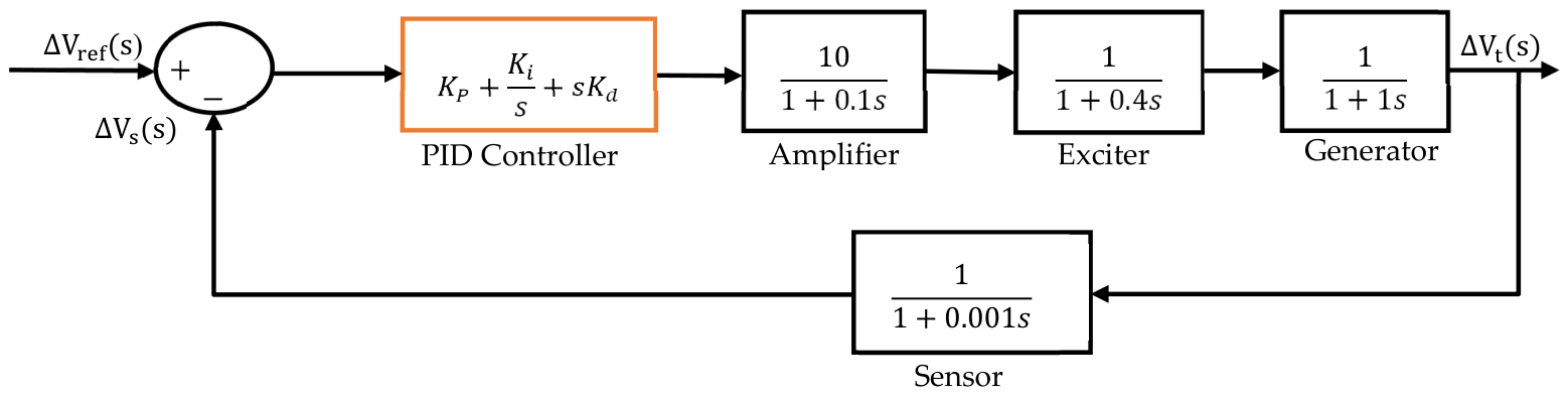
To regulate the generator output voltage Vs, a classical PID controller is commonly incorporated into the system.
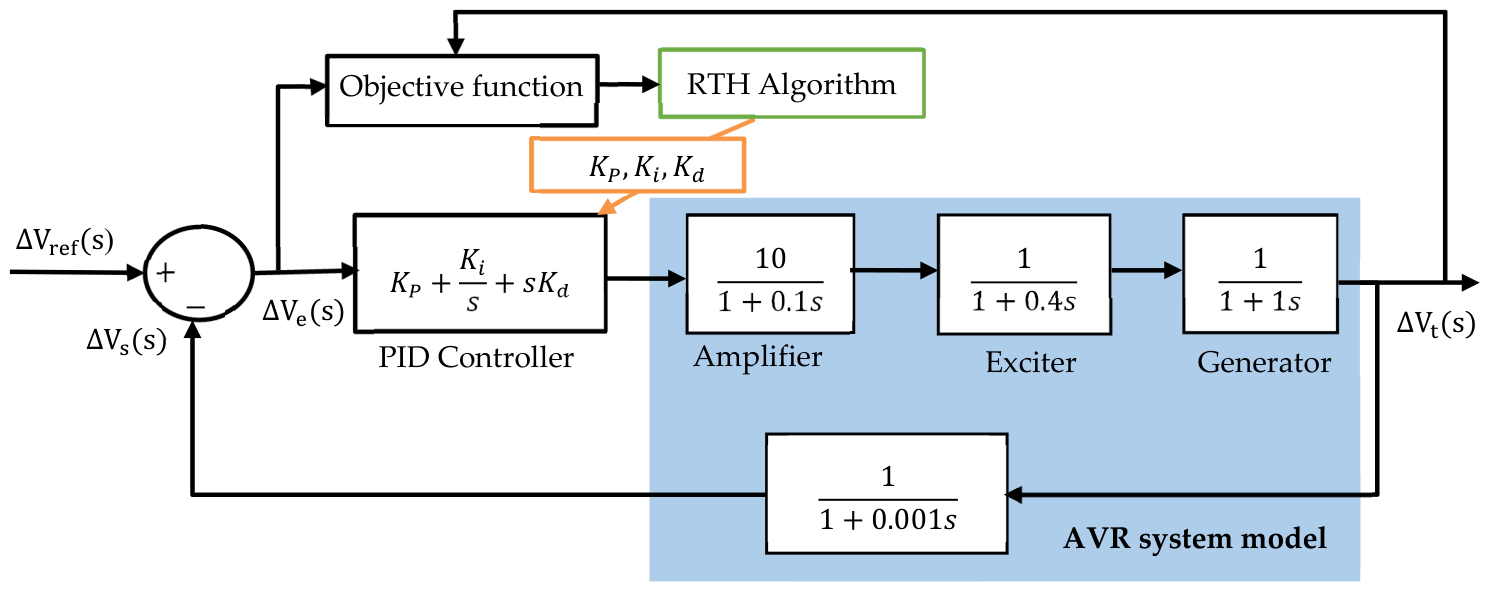
This type of controller is widely adopted due to its effectiveness in enhancing system performance through the combined action of the proportional, integral, and derivative terms, which collectively contribute to improved dynamic response. The schematic in Figure 4 illustrates the comprehensive transfer function model of an AVR system based on the PID controller.

3. Problem Formulation

In this study, a multi-objective function combining the time-weighted squared error (ITSE), as well as Zwe-Lee Gaing (ZLG), is proposed. These performance indices are widely recognized in the literature as effective objective functions to be minimized for AVR systems [10]. The ITSE criterion primarily focuses on suppressing large errors over time, while ZLG emphasizes time-domain performance characteristics such as maximum overshoot, rise time, and settling time. Their combination enables the optimizer to simultaneously minimize both transient and steady-state errors. The detailed formulation of this function is presented in the following section:
The performance index associated with ITSE is defined by the following expression:
I T S E = 0 t   s i m t e 2 t d t
where tsim denotes the total simulation time, and e(t) denotes the error signal defined as e(t) = Vref − Vs(t), with Vs(t) being the measured (output) voltage of the system.
The performance index associated with ZLG is defined by the following expression:
Z I G = ( 1 e β ) ( M p E s s ) + e β ( T s T r )
where β, Mp, Ts, Tr, and Ess represent the weighting factor, maximum percentage overshoot, settling time, rise time, and steady-state error, respectively. In this study, β is set to 1.5 to reduce the maximum overshot, and it can vary in the range of (0.5–1.5).
In this work, a combined objective function integrating ITSE and ZLG is suggested to enhance the AVR system transient response, and it is expressed by the function f(K) as follows:
f ( K ) = α × I T S E + Z L G
where α is a suitable weighting factor used to balance the target function values, which was selected as 10; this weighting factor was chosen for this study based on the reference study in [10] to guarantee consistency and a fair comparison with previously published results. Moreover, f(K) is investigated by adjusting the settings of control variables than can be expressed by vector u as follows:
u = [ K p , K i , K d ]
where
K p m i n   K p K p m a x K i m i n K i K i m a x K d m i n K d K d m a x
where max and min superscripts refer to maximum and minimum controller parameter values. In this study, the gains for PID controller tuning range between 0.2 and 2.0, as shown in Table 1.
Table 1. The main characteristics of the AVR-PID.
ComponentLimitsSet Value
PID controllerKp[0.2, 2.0]optimized value
Ki[0.2, 2.0]optimized value
Kd[0.2, 2.0]optimized value
AmplifierKa[10, 40]10
Ta[0.02, 0.1]0.1
ExciterKe[1.0, 10]1.0
Te[0.4, 1.0]0.4
GeneratorKg[0.7, 1.0]1.0
Tg[1.0, 2.0]1.0
SensorKs[0.9, 1.1]1.0
Ts[0.001, 0.06]0.01
The parameter limits and chosen values of the primary elements utilized in a synchronous generator’s excitation control system are shown in Table 1. To guarantee appropriate system stability and dynamic performance, a PID controller is tuned using these parameters.

4. Red-Tailed Hawk (RTH) Algorithm

This section introduces the proposed red-tailed hawk (RTH) algorithm to tune the PID controller parameters. This algorithm draws inspiration from the hunting strategies of red-tailed hawks in nature. The algorithm models the red-tailed hawk’s actions across three main stages: high soaring, low soaring, and stooping and swooping, which capture both exploration and exploitation behaviors [29].
The high-flying stage is mathematically described by Equation (11), where the hawk flies at a high altitude to explore the search area with minimal energy use.
X ( n ) = X b e s t + ( X m e a n X ( n 1 ) ) \ L e v y ( d i m ) \ T F ( n )
where  X  represent the red-tailed hawk position at iteration n, Xbest denotes the optimal position, Xmean is the positions’ average, and Levy represents the Levy flight distribution function, given in Equation (7) as follows:
L ( d i m ) = 0.01 μ × σ v β 1
where dim denotes the problem dimension, β is a constant (equal 1.5), and µ and v are random values between 0 and 1. The transition factor TF function can be calculated using the following equation:
T F ( n ) = 1 + sin ( 2.5 + ( n N m a x ) )
where nmax represents the maximum number of iterations. The low-flying stage is mathematically described by Equation (14), where the red-tailed hawk flies at a low altitude in a spiral trajectory to refine its position and determine the best place to attack its prey:
X ( n ) = X b e s t + ( x ( n ) + y ( n ) ) × S t e p S i z e ( n )
With
S t e p S i z e ( n ) = X ( n ) X m e a n
where x and y are direction coordinates, which can be determined as follows:
x n   =   R n   ·   s i n   θ n y n   =   R n   ·   c o s θ n R n = R 0 r n N m a x · r a n d   x ( n ) = x ( n ) max x ( n ) θ n = A 1 t N m a x · r a n d y ( n ) = y ( n ) max y ( n )
where rand is a random gain within (0–1), r is a control gain ranging from (1–2), A denotes the angle gain (5–15), and R0 is the radius’s starting value (0.5–3).
The stooping and swooping stage mathematical method is represented by Equation (17), where the hawk rapidly stoops and attacks the prey from the optimal position obtained in the last stage (low-flying).
X ( n ) = α ( n ) × X b e s t + x ( n ) ) × S t e p S i z e 1 ( n ) + y ( n ) × S t e p S i z e 2 ( n )
where the acceleration factor and gravity factor may be calculated employing the following Equations (18) and (19):
α ( n ) = sin 2 ( 2.5 n N m a x )
G ( n ) = 1 n N m a x
while the size of both steps 1 and 2 can be determined as follows:
S t e p S i z e 1 ( n ) = Y ( n ) T F n · Y m e a n
S t e p S i z e 2 ( n ) = G ( n ) · Y ( n ) T F ( n ) · Y b e s t
Figure 5 illustrates the block diagram of the AVR system incorporating the RTH-based PID controller.
The pseudo-code of the proposed algorithm, RTH, is described in Algorithm 1.
Algorithm 1: RTH pseudo-code.
1:  Initialization: Generate the initial population randomly.
2:  While n < Nmax do
3:   % High-flying stage
4:    for i = 1: Npop do
5:      Compute the Levy using Equation (12)
6:      Calculate the TF using Equation (13)
7:      Update the positions of red-tailed hawk according to Equation (11)
8:    end
9:   % Low flying stage
10:    for i = 1: Npop do
11:      Calculate direction coordinates using Equation (16)
12:      Update positions using Equation (14)
13:    end
14:   % Stooping and Swooping stage
15:    for i = 1: Npop do
16:      Calculate the  α  and  G  factors using Equations (18) and (19)
17:      Calculate both step sizes using Equations (20) and (21)
18:      Update positions of red-tailed hawk using Equation (17)
19:    ends
20: end

5. Results and Discussion

This study proposes employing the RTH algorithm to optimize the PID controller parameters of an AVR system. A multi-objective function, combining ITSE and ZLG criteria, is introduced to enhance the system’s transient response in terms of overshoot (Mp), rising time (Tr), settling time (Ts), error steady state (Ess), and peak time (Tp). The simulations were carried out using the MATLAB R2021a programming environment on a personal computer equipped with an Intel® Core™ i5-7300U CPU operating at 2.60 GHz and 8 GB of RAM. To evaluate the effectiveness and superiority of the proposed RTH-based approach, several key parameters were considered, including three control variables, a population size of 30, a maximum of 30 iterations, and 40 independent trial runs.
To demonstrate the effectiveness and superiority of the proposed RTH-PID controller, its transient response characteristics are compared with other optimally tuned PID controllers reported in the literature, such as BBO-PID [14], HSA-PID [19], IKA-PID [10], SCA-PID [8], SFS-PID [22], SOS-PID [24], and WOA-PID [5]. The comparison of results achieved through the proposed RTH-PID controller and these controllers is presented in Table 2.
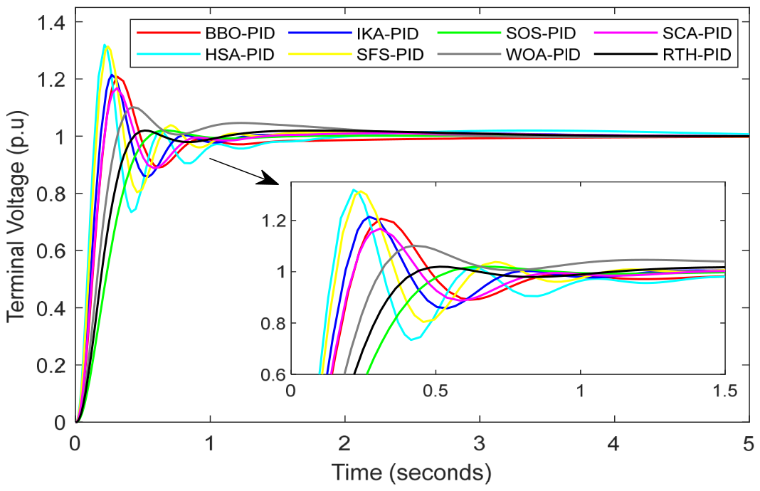
The RTH algorithm outperforms the other methods by effectively balancing key response characteristics. Compared to algorithms such as HSA (1.3614%) and SFS (1.3587%), it achieves the lowest overshoot (Mp = 1.019%), reflecting greater stability and reduced oscillations in the system response. In addition, RTH provides the fastest rise time (Tr = 0.264 s) along with the shortest settling times at both 5% and 2% criteria (Ts5% = 0.374 s, Ts2% = 0.4044 s). In contrast, algorithms like BBO and HSA exhibit settling times exceeding one second, indicating slower dynamics and lower overall performance. Based on these results, the RTH algorithm can be regarded as the most effective among the studied methods, as it combines a rapid response with strong system stability, making it an optimal choice for improving AVR system performance. The findings clearly demonstrate that, for AVR regulation, the proposed RTH-PID controller outperforms the other optimally tuned PID controllers.
In addition, Figure 5 presents the simulation results comparison of the measured terminal voltage step response of the AVR system using the RTH-PID controller and other controllers. From this figure, it is evident that the RTH-based PID tuning significantly reduces overshoot and improves oscillation damping compared to the other approaches. These results clearly demonstrate that the proposed RTH-PID controller outperforms the other optimally tuned PID controllers in regulating the AVR system

5.1. Root Locus Analysis

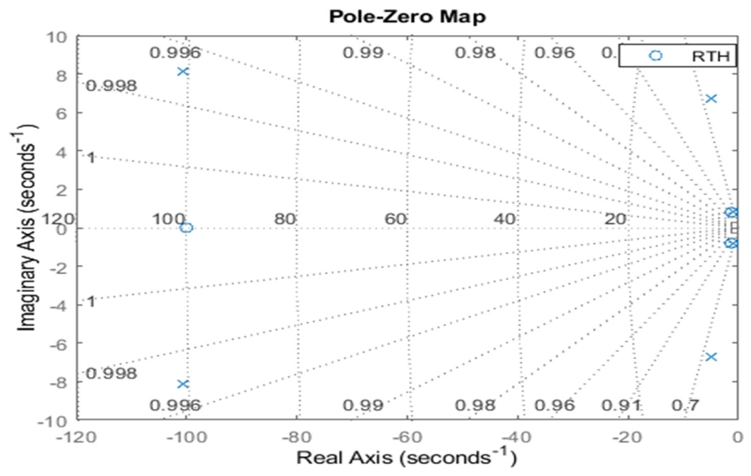
Figure 6 illustrates the root locus of the system using the RTH algorithm. The pole-zero map confirms that all closed-loop poles are located in the left half of the complex plane, indicating system stability. Compared to the open-loop response, the damping ratios fall within an acceptable range, reflecting improved stability and enhanced damping characteristics of the system.
Figure 7 shows the root locus of the RTH-PID controller, while Table 3 summarizes the closed-loop poles and damping ratios for all controllers. From this table, all poles are located in the left half of the s-plane, confirming system stability. Notably, the RTH-PID controller places its poles further from the imaginary axis, resulting in faster dynamics and improved damping, as reflected by higher damping ratios (0.59, 0.841, and 0.997) and more negative real parts. In contrast, HSA-PID and SFS-PID exhibit lower damping ratios, leading to more oscillatory responses, while IKA-PID shows moderate performance. As conclusion, the RTH-PID controller provides superior stability and damping, ensuring smooth and reliable system behavior.

5.2. Bode Analysis

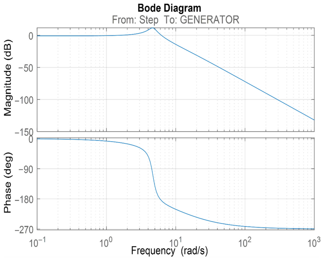
The frequency response of the control is analyzed through a Bode plot. The magnitude and phase plot of the AVR system tuned by the RTH algorithm is shown in Figure 8.
A comparative analysis of various optimization methods in terms of bandwidth and stability margins, including the peak margin, phase margin, and delay margin, is shown in Table 4. These metrics are crucial for evaluating a system’s stability under time delays, disturbances, and its response to dynamic frequencies.
Among the evaluated controllers, the RTH-PID controller achieves the longest delay margin (2.1082 s) and the biggest phase margin (163.15°), indicating strong robustness and an enhanced ability to maintain stability under uncertainties and time delays. Some controllers, such as HSA-PID and SFS-PID, exhibit significantly lower phase margins (e.g., just 58.3° for HSA), which may result in decreased system stability and a higher risk of oscillatory behavior, even if they display larger bandwidths (22.1 and 19.8 rad/s, respectively).
On the other hand, RTH-PID is the most dependable choice for control applications that demand both safety and dynamic responsiveness because it strikes the perfect mix between an adequate bandwidth (8.60 rad/s) and extremely large stability margins.

5.3. Robustness Analysis

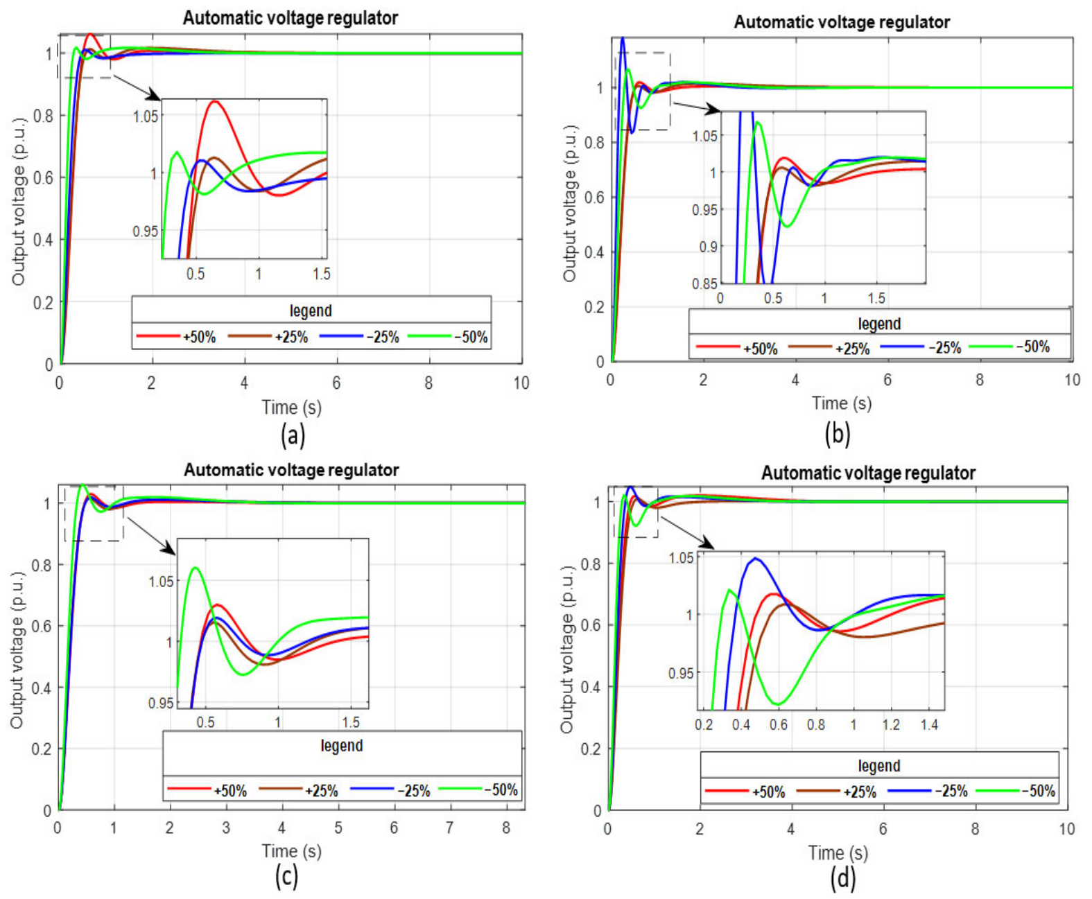
To evaluate the robustness of the RTH-optimized PID controller applied to the AVR system under parametric variations, the time constants of the amplifier, exciter, generator, and sensor are varied from −50% to +50% in increments of 25%. The resulting transient response parameters, such as maximum overshoot, settling time, rise time, and peak time, for the AVR system controlled by the RTH-based PID algorithm are presented in Table 5.
Figure 9 illustrates the terminal voltage response under variations of the time constants of the amplifier (Ta), generator (Tg), sensor (Ts), and exciter (Te). The results show that decreasing Ta significantly improves dynamic performance by reducing overshoot and settling time while accelerating the response. Variations in Tg reveal a trade-off between speed and stability, where reductions lead to faster rise times but increased overshoot and longer settling. In contrast, changes in Ts have minimal impact on system behavior, indicating strong robustness with respect to sensor dynamics. However, increasing Te degrades performance by increasing oscillations and prolonging settling time, while moderate variations provide a more balanced response. Overall, the AVR system shows improved performance with reduced Ta and appropriate tuning of Tg and Te, while remaining insensitive to Ts variations. Moreover, the RTH-PID controller exhibits strong robustness against parameter variations, particularly in Ta and Ts. However, special attention must be given to Tg, as its reduction may negatively impact system stability.

6. Conclusions

This study investigates the effectiveness of the red-tailed hawk (RTH) metaheuristic algorithm in optimally tuning PID controller parameters for an automatic voltage regulator (AVR) under varying operating conditions, including parameter uncertainties. The proposed system is evaluated through stability and robustness analyses, using root locus and Bode diagrams for stability assessment and transient response analysis under AVR parameter variations for robustness. In this context, the proposed RTH-PID controller is designed to minimize a multi-objective performance index that integrates the time-weighted squared error (ITSE) and the Zwe-Lee Gaing (ZLG) criterion to enhance system performance. The obtained results reveal that the RTH-PID controller provides superior dynamic and steady-state performance compared to other tuning methods, such as BBO, IKA, SOS, SCA, HSA, SFS, and WOA, achieving reduced rise time, settling time, and overshoot, along with enhanced steady-state accuracy. In particular, it ensures faster convergence, improved damping characteristics, and greater robustness against system parameter variations and external disturbances. This comparison confirms the superiority of the proposed controller in terms of convergence speed and overall control performance. Future work will concentrate on developing gain-scheduled and adaptive PID variants that can adapt to shifting system conditions, conducting experiments to verify real-time performance, and expanding the RTH algorithm to other power system control applications, such as active power load variation and power system stabilizer design.

Author Contributions

R.A.e.: conceptualization, methodology, writing—original draft, investigation; K.R.: supervision, original draft revision, formal analysis; S.M.: draft review, formal analysis, software; L.T.: conceptualization, writing—review and editing. All authors have read and agreed to the published version of the manuscript.

Funding

This research received no external funding.

Data Availability Statement

Data are contained within the article. The original contributions presented in this study are included in the article. Further inquiries can be directed to the corresponding author.

Acknowledgments

This work was conducted at Ferhat Abbas University of Sétif 1, within the Department of Electrical Engineering. The first author would like to express sincere appreciation to all co-authors for their valuable support and guidance throughout the course of this research. The authors also gratefully acknowledge Ferhat Abbas University for providing a supportive research environment that facilitated the successful completion of this study.

Conflicts of Interest

The authors declare no conflicts of interest.

Abbreviations

The following abbreviations are used in this manuscript:
RTHRed-tailed hawk
AVRAutomatic voltage regulator
ZLGZwe-Lee Gaing
ITSETime-weighted squared error
PIDProportional-Integral-Derivative

References

  1. Ozgenc, B.; Ayas, M.S.; Altas, I.H. Performance improvement of an AVR system by symbiotic organism search algorithm-based PID-F controller. Neural Comput. Appl. 2022, 34, 7899–7908. [Google Scholar] [CrossRef]
  2. Sahib, M.A. A novel optimal PID plus second order derivative controller for AVR system. Eng. Sci. Technol. Int. J. 2015, 18, 194–206. [Google Scholar] [CrossRef]
  3. Mohamed, M.J.; Abood, L.H. Performance Evolution of Different Optimal Controllers for Controlling AVR System. J. Eur. Syst. Autom. 2023, 56, 973–979. [Google Scholar] [CrossRef]
  4. Sivanandhan, A.; Thriveni, G. Optimal design of controller for automatic voltage regulator performance enhancement: A survey. Electr. Eng. 2024, 106, 7305–7320. [Google Scholar] [CrossRef]
  5. Mosaad, A.M.; Attia, M.A.; Abdelaziz, A.Y. Whale optimization algorithm to tune PID and PIDA controllers on AVR system. Ain Shams Eng. J. 2019, 10, 755–767. [Google Scholar] [CrossRef]
  6. Sun, J.; Wu, L.; Yang, X. Optimal Fractional Order PID Controller Design for AVR System Based on Improved Genetic Algorithm. In Proceedings of the IEEE International Conference on Advances in Electrical Engineering and Computer Applications (AEECA), Dalian, China, 25–27 August 2020. [Google Scholar]
  7. Şahin, Y.; Bingol, M.S.; Savas, S. Tuning PID controller parameters of the DC motor with PSO algorithm. Int. Rev. Appl. Sci. Eng. 2024, 3, 281–286. [Google Scholar] [CrossRef]
  8. Hekimoğlu, B. Sine-cosine algorithm-based optimization for automatic voltage regulator system. Trans. Inst. Meas. Control 2019, 41, 1761–1771. [Google Scholar] [CrossRef]
  9. Agathiyan, A.; Vinothkumar, B.; Akgul, A.; Alshammari, F.S. Fractal–fractional modeling and chaos analysis of a financial system with generalized memory kernels. Results Control. Optim. 2025, 21, 100632. [Google Scholar] [CrossRef]
  10. Ekinci, S.; Hekimoglu, B. Improved Kidney-Inspired Algorithm Approach for Tuning of PID Controller in AVR System. IEEE Access 2019, 7, 39935–39947. [Google Scholar] [CrossRef]
  11. Kotb, H.; Yakout, A.H.; Attia, M.A.; Turky, R.A.; Aboras, K.M. Speed control and torque ripple minimization of SRM using local unimodal sampling and spotted hyena algorithms based cascaded PID controller. Ain Shams Eng. J. 2022, 13, 101719. [Google Scholar] [CrossRef]
  12. Bam, G.; Guchhait, P.K.; Banerjee, A.; Deepa, S.N. Symbiosis organisms search algorithm for reactive power compensation of STATCOM-PID assisted isolated wind integrated hybrid power system model. Electr. Power Syst. Res. 2024, 227, 109949. [Google Scholar] [CrossRef]
  13. Li, H.; Yang, Y.; Wang, Y.; Li, J.; Yang, H.; Tang, J.; Gao, S. Heliyon Population interaction network in representative gravitational search algorithms: Logistic distribution leads to worse performance. Heliyon 2024, 10, e31631. [Google Scholar] [CrossRef] [PubMed]
  14. Güvenç, U.; Yiǧit, T.; Işik, A.H.; Akkaya, I. Performance analysis of biogeography-based optimization for automatic voltage regulator system. Turk. J. Electr. Eng. Comput. Sci. 2016, 24, 1150–1162. [Google Scholar] [CrossRef]
  15. Jabari, M.; Rad, A. Optimization of Speed Control and Reduction of Torque Ripple in Switched Reluctance Motors Using Metaheuristic Algorithms Based PID and FOPID Controllers at the Edge. Tsinghua Sci. Technol. 2025, 30, 1526–1538. [Google Scholar] [CrossRef]
  16. Omar, M.H.T.; Hamdy, R.A.; Kotb, H. A hybrid fuzzy-PIDD2 control strategy for coordinated LFC and AVR in renewable-integrated multi-area power systems. Sci. Rep. 2026, 16, 3741. [Google Scholar] [CrossRef]
  17. Chatterjee, S.; Mukherjee, V. Electrical Power and Energy Systems PID controller for automatic voltage regulator using teaching–learning based optimization technique. Int. J. Electr. Power Energy Syst. 2016, 77, 418–429. [Google Scholar] [CrossRef]
  18. Saha, J.; Guha, D.; Jha, S.K. Voltage Control of Power System employing Q-Learning based PID Controller. In Proceedings of the 2022 IEEE 19th India Council International Conference (INDICON), Kochi, India, 24–26 November 2022. [Google Scholar]
  19. Mosaad, A.M.; Attia, M.A.; Abdelaziz, A.Y. Comparative Performance Analysis of AVR Controllers Using Modern Optimization Techniques. Electr. Power Compon. Syst. 2018, 46, 2117–2130. [Google Scholar] [CrossRef]
  20. Gao, Y. PID-based search algorithm: A novel metaheuristic algorithm based on PID algorithm. Expert Syst. Appl. 2023, 232, 120886. [Google Scholar] [CrossRef]
  21. Mahider, K.I.; Rabeh, R.; Ferfra, M. Design of novel control strategy of STATCOM with two PID and cascaded PID and FOPID tuned by combined GA-PSO algorithm. Sci. Afr. 2026, 32, e03296. [Google Scholar] [CrossRef]
  22. Çelik, E. Incorporation of stochastic fractal search algorithm into efficient design of PID controller for an automatic voltage regulator system. Neural Comput. Appl. 2018, 30, 1991–2002. [Google Scholar] [CrossRef]
  23. Suid, M.H.; Ahmad, M.A. Optimal tuning of sigmoid PID controller using Nonlinear Sine Cosine Algorithm for the Automatic Voltage Regulator system. ISA Trans. 2022, 128, 265–286. [Google Scholar] [CrossRef]
  24. Çelik, E.; Durgut, R. Performance enhancement of automatic voltage regulator by modified cost function and symbiotic organisms search algorithm. Eng. Sci. Technol. Int. J. 2018, 21, 1104–1111. [Google Scholar] [CrossRef]
  25. Khaniki, M.A.L.; Hadi, M.B.; Manthouri, M. Feedback Error Learning Controller based on RMSprop and Salp Swarm Algorithm for Automatic Voltage Regulator System. In Proceedings of the 10th International Conference on Computer and Knowledge Engineering (ICCKE), Mashhad, Iran, 29–30 October 2020. [Google Scholar]
  26. Sekyere, Y.O.M.; Ajiboye, P.O.; Effah, F.B.; Opoku, B.T. Optimizing PID control for automatic voltage regulators using ADIWACO PSO. Sci. Afr. 2025, 27, e02562. [Google Scholar] [CrossRef]
  27. Andiç, C. A Novel Superb Fairy-Wren Optimization Algorithm Based PID Controller for an Automatic Voltage Regulator System. Appl. Sci. 2026, 16, 856. [Google Scholar] [CrossRef]
  28. Izci, D.; Ekinci, S.; Jabari, M.; Kocaman, B.; Güneş, B.B.; Adas, E.; Ahmad, M.A. A Novel Gudermannian Function-Driven Controller Architecture Optimized by Starfish Optimizer for Superior Transient Performance of Automatic Voltage Regulation. Biomimetics 2026, 11, 7. [Google Scholar] [CrossRef] [PubMed]
  29. Ferahtia, S.; Houari, A.; Rezk, H.; Djerioui, A.; Machmoum, M.; Motahhir, S.; Ait-Ahmed, M. Red-tailed hawk algorithm for numerical optimization and real-world problems. Sci. Rep. 2023, 13, 12950. [Google Scholar] [CrossRef] [PubMed]
  30. Alshahrani, H.J.; Hassan, A.Q.A.; Almalki, N.S.; Alnfiai, M.M.; Salama, A.S.; Hamza, M.A. Applied Linguistics with Red-Tailed Hawk Optimizer-Based Ensemble Learning Strategy in Natural Language Processing. IEEE Access 2023, 11, 132448–132456. [Google Scholar] [CrossRef]
  31. Gbadega, P.A.; Sun, Y.; Balogu, O.A. Enhanced multi-area automatic generation control in renewable energy-based microgrids using an IPFC-SMES system and COA-optimized FOPID controller. Energy Rep. 2025, 13, 6479–6513. [Google Scholar] [CrossRef]
Figure 1. A practical AVR system model.
Processes 14 01550 g001
Figure 2. The AVR system block diagram.
Processes 14 01550 g002
Figure 3. Terminal voltage step response of an AVR system.
Processes 14 01550 g003
Figure 4. Modeling of the AVR-PID system.
Processes 14 01550 g004
Figure 5. The AVR-PID system model tuned by the RTH algorithm.
Processes 14 01550 g005
Figure 6. Step response comparison of voltage-changing curves of optimized PID controllers.
Processes 14 01550 g006
Figure 7. Root locus of RTH-PID controller.
Processes 14 01550 g007
Figure 8. Analysis of the RTH-based AVR system.
Processes 14 01550 g008
Figure 9. Terminal voltage by varying time constant: (a) Ta, (b) Tg, (c) Ts, (d) Te.
Processes 14 01550 g009
Table 2. Performance comparison of optimized PID controllers.
OptimizationKpKiKdMax Overshoot (Mp) (%) Settling Time (Ts) (s) (5%)Settling Time (Ts) (s) (2%)Rise Time (Tr) (s)Peak Time (Tp) (s)
RTH-PID0.618140.561180.239081.0190.3740.40440.2640.568
WOA-PID [5]0.78470.99610.30611.11860.58592.11550.19690.4340
SCA-PID [8]0.98260.83370.49821.19030.74050.79710.13590.2857
IKA-PID [10]1.04261.00930.61.24920.67901.12090.11950.2814
BBO-PID [14]1.24640.58930.45961.23620.78121.42920.13730.3315
HSA-PID [19]0.868320.932540.94191.36141.26591.42960.08750.2317
SFS-PID [22]1.28371.33920.77801.35870.95421.03570.09760.2372
SOS-PID [24]0.56930.40970.17501.02750.45200.75460.32270.6461
Table 3. Closed-loop poles and damping ratios of the AVR system.
ControllerClosed-Loop System PolesDamping Ratio
RTH-PID−1001
−1.28 + 0.803i0.847
−1.28 − 0.803i0.847
−4.93 + 6.72i0.592
−4.91 − 6.72i0.592
−101 + 8.15i0.997
−101 − 8.15i0.997
BBO-PID−100.01
−2.11
−05851
−4.8 + 10.2i0.427
−4.8 − 10.2i0.427
IKA-PID−1021
−5.13 + 11.7i0.40
−5.13 − 11.7i0.40
−0.80 + 0.93i0.65
−0.80 − 0.93i0.65
SOS-PID−100.481
−1.981
−1.101
−4.97 + 4.69i0.727
−4.97 − 4.69i0.727
SCA-PID−101.371
−5.16 + 10.52i0.44
−5.16 − 10.52i0.44
−0.91 + 0.82i0.74
−0.91 − 0.82i0.74
HSA-PID−1031
−5.04 + 15.1i0.316
−5.04 − 15.1i0.316
−0.45 + 0.85i0.465
−0.45 − 0.85i0.465
SFS-PID−102.111
−0.77 + 1.0i0.62
−0.77 − 1.0i0.62
−4.93 + 13.5i0.35
−4.93 − 13.5i0.35
WOA-PID−101
−5.24 + 7.64i0.565
−5.24 − 7.64i0.565
−1.09 + 1.3i 0.642
−1.09 − 1.3i0.642
Table 4. Comparison of the bandwidth and margin results for various PID controllers.
Peak Margin (db)Phase Margin (Degree)Delay Margin (s)Bandwidth (rad/s)
RTH-PID17.9703163.152.10828.6038
WOA-PID [5]0.5691551.049.9
SCA-PID [8]1.0987.30.12814.821
IKA-PID [10]1.78 76.70.09516.785
BBO-PID [14]1.5681.60.12214.28
HSA-PID [19]3.5458.30.052522.1
SFS-PID [22]3.1162.4 19.8
SOS-PID [24]0.0180Inf.6.15
Table 5. Robustness analysis of the RTH algorithm-based PID-controlled AVR system.
ParameterRate of Variation (%)Overshoot
Mp %
Settling Time (s) 2%Settling Time (s) 5%Rise Time (s)Peak Time
Ta Amplifier+501.06190.85670.73990.31730.6363
+251.01660.50460.46370.32891.9552
−251.01040.42070.38260.27220.5262
−501.01790.26370.24310.17250.3455
Te Exciter+501.01990.44640.41090.29132.0152
+251.03410.34030.98740.24050.4733
−251.04870.60370.33070.23450.4735
−501.02130.84450.73120.18150.3342
Tg Generator+501.01920.46380.42760.30500.5936
+251.01470.46610.42320.29922.0197
−251.18240.61520.57890.10780.2398
−501.06770.85130.75140.17500.3388
Ts Sensor+501.02990.67380.40740.29060.5765
+251.01540.43780.40280.28580.5518
−251.01920.44100.40610.28870.5771
−501.06040.85570.48250.21080.4242
Disclaimer/Publisher’s Note: The statements, opinions and data contained in all publications are solely those of the individual author(s) and contributor(s) and not of MDPI and/or the editor(s). MDPI and/or the editor(s) disclaim responsibility for any injury to people or property resulting from any ideas, methods, instructions or products referred to in the content.