Article

Improving Health and Safety in Welding Through Remote Human–Robot Collaboration

1
Institute for Material Science and Welding Techniques, University of Applied Science Hamburg, 20099 Hamburg, Germany
2
Research and Transfer Centre FTZ-3i, University of Applied Science Hamburg, 20099 Hamburg, Germany
*
Authors to whom correspondence should be addressed.
Processes 2025, 13(9), 3017; https://doi.org/10.3390/pr13093017
Submission received: 1 August 2025 / Revised: 10 September 2025 / Accepted: 18 September 2025 / Published: 21 September 2025

Abstract

Welding is an essential process across various industries; however, it exposes workers to dangerous fumes, extreme heat and physical stress, which pose considerable health and safety hazards. To tackle these issues, this article introduces the creation of a remote-controlled human–robot welding system aimed at safeguarding workers while ensuring the quality of the welds. The system monitors a welder’s torch movements through a stereoscopic sensor and accurately reproduces them with a robotic arm, facilitating real-time remote welding. Operated by a student, it effectively welded standardized sheet metals in overhead positions while adhering to critical quality standards. The weld geometry met ISO 5817 requirements, tensile strength surpassed the base material specifications, and bending and hardness assessments verified the durability and integrity of the welds. When utilized in hazardous settings, the system showcases its capability to produce high-quality welds while significantly enhancing worker safety, underscoring its potential for real-world industrial applications.

1. Introduction

Europe is facing significant societal challenges due to demographic shifts. In 2015, approximately 19% of the European population was over the age of 65, and this proportion is expected to grow in the coming years. To address the strain on pension systems, many European governments have raised the retirement age, resulting in an increase in employment rates for individuals aged 55 to 64—from around 40% in 2003 to 50% in 2013 [1,2]. However, extending working life presents serious issues for individuals in physically demanding jobs, such as welders. Without adjustments to their work environment, these workers often face strenuous conditions, including awkward physical positions, exposure to harmful fumes, outdoor work in varying weather, and the requirement to wear heavy or uncomfortable protective equipment. In many cases, welders avoid wearing safety equipment—26% reportedly never use a respiratory mask—which not only disrupts workflow and reduces productivity but also endangers their health. As workers age, the risk of extended sick leave and chronic illness increases, despite improvements in workplace safety laws and employment protections [3,4]. From a broad perspective, work-related accidents and illnesses impose a substantial financial burden across Europe. As shown in Figure 1A,B, the total cost of such incidents within the EU-28 is estimated at EUR 476 billion, representing 3.3% of the region’s gross domestic product (GDP). Additionally, 22% of all work-related deaths result from workplace accidents, with a notable share occurring in the metal processing industry [5].
Many tasks in heavy industries rely heavily on manual labour due to the specialized skills and experience workers develop over time, which form the core expertise of companies in these sectors. Such industries include maintenance and repair, boiler and tank construction, shipbuilding, power plant and nuclear facility operations, and steel construction. Consequently, these skilled tasks cannot be easily replaced by sensor-equipped machines [6]. Typical jobs involve processes like welding, gouging, thermal cutting, high-pressure cleaning, and air hammering, all of which expose workers to hazardous conditions such as noise, smoke, radiation (gamma, UV), vibration, electric shock, moisture, and heat. Often, these tasks are performed in tight, confined spaces such as boilers, containers, or bulkheads. As a result, workers may suffer from physical ailments including musculoskeletal disorders, back pain, joint and knee problems, lung diseases, and hearing or eye conditions such as hearing loss and arc eye [7,8].
Thus, employees are exposed to difficult conditions while exercising their jobs. These working conditions disproportionately burden the health of employees with increasing age. The consequences of such working conditions are much more serious for older employees than for younger ones. As a result, older employees are more likely to get sick, and curing the illness takes longer than expected. These conditions lead to worsening of living conditions, as the quality of life deteriorates due to illness. In some cases, employees may no longer be able to carry out their jobs due to accidents [9,10]. These are retrained at best and have to perform other activities that do not reflect their original interest, though have to be performed. In the worst case, accidents and illnesses lead to premature job losses. As a result of disease and accidents older unemployed people will also be faced with mental problems such as depression [11,12].
“Work-related musculoskeletal disorders” (WMDs) is an umbrella term that describes a wide range of injuries that affect the muscles, tendons, ligaments and nerves. These disorders reduce the ability of affected individuals to perform sequences of movements and may lead to permanent disability in extreme cases. Muscular skeletal disorders/injuries can occur as a gradual build up over time or can manifest as a seemingly sudden ‘blow out’. WMDs are one of the major health issues of young and old welders [13]. Plouvier et al. (2011) explored the incidence of back pain around retirement age in relation to physical occupational exposures [14]. The authors found that the prevalence of lower back pain for more than 30 days within the previous 12 months among those exposed to manual material handling and/or tiring postures progressively increased through the age groups 45–49, 50–54 and 55–59 (retirement at 60).
Yeomans (2011) cited several studies concluding that the increased prevalence of WMDs with age is most pronounced in workers involved in physically demanding jobs, irrespective of age [15]. A study by Ilmarinen (2002, cited by Yeomans, 2011) found that an increased prevalence of WMDs with age was most pronounced among those who remained in the same occupation and who were exposed to physically demanding work [15,16,17,18,19]. This suggests that a cumulative exposure factor is involved in addition to work demands. Okunribido & Wynn (2010) cited several studies suggesting that employees in physically demanding occupations and exposed to challenging tasks are more likely to report underlying health problems than those in sedentary occupations [13]. A study conducted among U.S. employees revealed that work-related musculoskeletal disorders (WMDs) led to 10% of employees missing work and accounted for 50% of chronic conditions among workers over the age of 50. Moreover, WMDs will be the reason for a huge number of surgeries for various implants and their post-surgery care. This highlights a strong need to improve working conditions in order to reduce their impact on employees’ health status. In 2009, the German Federal Institute for Occupational Safety and Health systematically examined the distribution of work disability due to musculoskeletal disorders by occupation (Liebers and Caffie 2009) [20]. The report delineates the musculoskeletal regions disproportionately affected among welders relative to other occupational groups. The most commonly affected regions, in descending order of frequency [17], include the following:
  • Disorders of the back, particularly involving the spine
  • Disorders of the tendons, tendon calcifications, and joint capsules
  • Shoulder lesions
  • Chronic inflammation of the knee joint
  • Chronic inflammation of the hip joint
Strained working conditions, particularly those involving awkward postures, contribute to three main age-related changes that increase the risk of developing work-related musculoskeletal disorders (WMDs): reduced joint mobility, diminished muscle strength, and slower movement times (Okunribido & Wynn, 2010) [13]. Evidence shows that both the prevalence and incidence of WMDs rise with age [13,14]. The development of human–robot systems offers a promising solution, and several related studies are currently in progress. A digital twin (DT) platform integrating VR-based human–robot interaction was developed for welding and welder behaviour analysis. The system enables remote demonstration, robotic execution, and real-time VR feedback, enhancing user engagement. Experiments with skilled and unskilled welders, combined with Fast Fourier Transform (FFT)–Principal component analysis (PCA)–Support vector machine (SVM) analysis, achieved 94.4% accuracy in classifying behaviours, offering potential for improved novice training and productivity [21]. A real-time automated welding system was proposed in [22], by integrating a large joint dataset, with robotic vision, laser scanning, and path planning. Contributions include a robust joint detection, real-time seam tracking, joint centre adjustment, human–robot interaction for alignment, and integrated hardware-software control. Results showed improved welding efficiency in controlled environments, though applicability remains limited, highlighting the system as a foundational step toward scalable construction welding automation. A tracking system developed based on a YOLOv8S-seg-based weld seam tracking and inspection robot was developed with a lightweight MobileNetV3 backbone, C2fGhost module, and EMA attention to enhance accuracy. The system achieved 97.8% weld recognition with a compact 4.88 MB model and 54 ms processing time on Jetson Nano, enabling real-time, efficient seam detection and path planning [23]. To date, the developed systems have remained at the prototype stage though the system developed in [21] shows scope for industrial application; this paper aims to advance a fully implemented system for industrial use, emphasizing its economic feasibility.
Therefore, the project MeRItec aims to create a health- and safety-promoting working environment for older employees—particularly in welding and cutting—through the use of augmented reality (AR) in remote operations. In this concept, robots carry out welding and cutting tasks under the remote control of trained operators, effectively separating workers from hazardous environments. As a result, employees are spared both physical and mental strain, thereby supporting longer working lives and delayed retirement through a healthier work setting. Additionally, MeRItec integrates a digital health tool designed to encourage active breaks. During these breaks, employees engage in individualized mental and physical exercises that improve overall well-being and health. To ensure continuity, these exercises can also be performed at home, fostering sustainable health improvement. Overall, MeRItec provides a comprehensive solution by combining AR-based remote welding operations with health-promoting practices, ultimately enhancing the safety and longevity of older employees in demanding industrial environments [24,25,26,27]. The whole system was developed and tested based on feedback from the industrial partners (DINSE GmbH and SLV-Nord), considering different levels of user’s welding background.
The article begins in Section 2 by examining the development of the man-robot interface, focusing on methods to replicate the welder’s hand movements. Section 3 investigates the welding parameters required for overhead positions and presents them in a systematic manner. In Section 4, the quality of the welds is assessed in accordance with established standards, with results compared to those of manually welded seams. Finally, Section 5 summarizes and discusses the key findings.

2. Materials and Methods

2.1. Experimental Setup

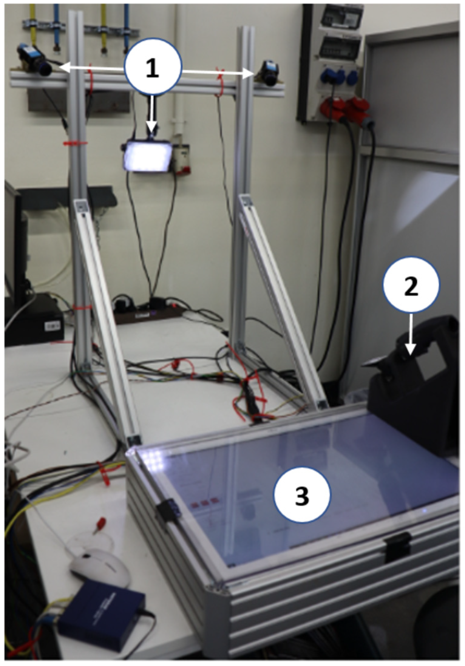
The system architecture was structured into two primary subsystems: the operator side and the robotic side. The operator side is an ergonomically adjustable workspace, free from welding-related emissions, and equipped for motion tracking as well as acoustic and visual feedback. It incorporates a stereoscopic measuring system that captures the operator’s manual movements. The system is directed towards the working area of the operator. It determines the pose of the torch-dummy with a repeating accuracy of <0.3 mm. The visual feedback display provides a usable working area of 400 mm × 600 mm × 400 mm for the operator (see Figure 2, marked as 3). Further in the figure, the camera and welding equipment marked as 1 and 2, respectively, can be seen. The referencing of the tool center point (TCP) is achieved through a pre-defined position on the visual feedback screen. The TCP and the orientation of the coordinates is evaluated optically with respect to the markers attached to the welding torch. In order to provide visual feedback of the welding process, a camera is attached to the robot, the image of which is displayed on a screen below the operator’s work surface [28,29].
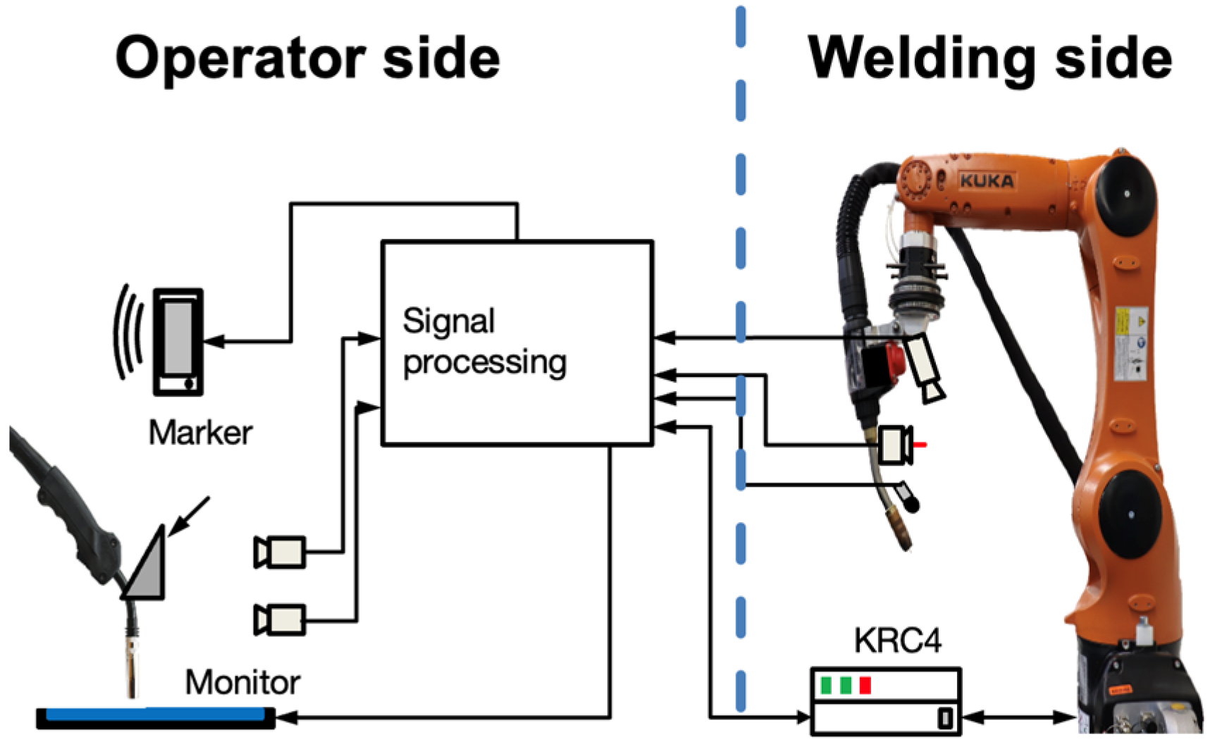
A standard KUKA KR6 Agilus R900 (KUKA AG, Augsburg, Germany) industrial robot was installed on the welding side. This lightweight robot has an operational reach of approximately 1 m and is easily transportable, requiring no specialized equipment for setup in the workspace. It offers high positional repeatability of ±0.03 mm, which is well within acceptable tolerances for welding tasks. The robot is operated using the KRC4 controller, and the Robot-Sensor Interface (RSI) [30] enables direct arm control over Ethernet. A WF 60i ROBACTA DRIVE CMT welding torch was mounted as the end effector for welding operations. Additionally, a Fronius TPi300 (Fronius International GmbH, Pettenbach, Austria) programmable power source was integrated into the robot’s control system [31], with its signals connected to the robot controller’s digital input/output interface using a proprietary bus converter. A pneumatic tool changer is also attached to the robot, enabling it to switch between various tools like brushes, scanners, and different torches, in addition to the welding torch. The entire robotic welding setup is housed within a welding cell equipped with an exhaust system and an adjustable-height safety shield, ensuring a secure environment for both the operator and nearby workers. A schematic of the system is shown in Figure 3.

2.2. Motion Signal Analysis, Path Generation and Final System Development

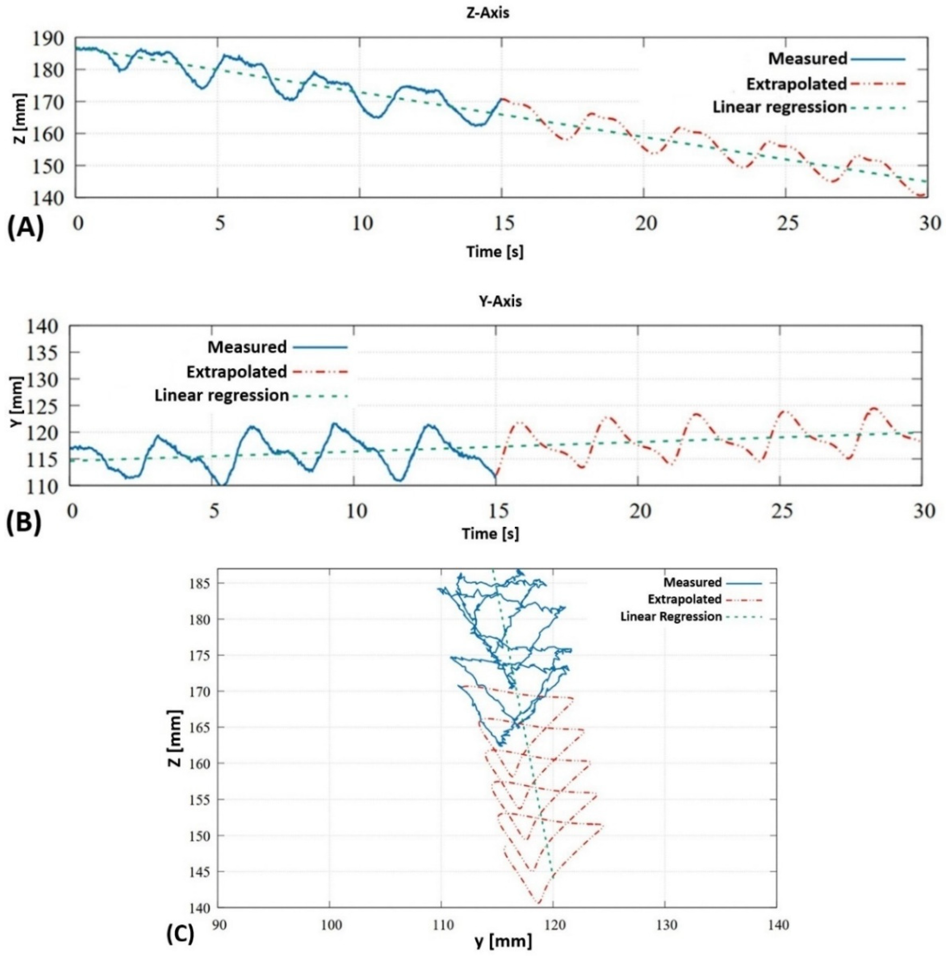
To ensure precise tracking performance, the KRC4 robot controller requires either an integrated second-order low-pass filter or a C2-continuous reference trajectory, due to the way data is processed within the controller. Minimizing phase lag in the control loop is essential to ensure the operator experiences responsive and intuitive system behaviour. To address this, the bandwidth of relevant signal components was determined (see Figure 4A,B) by performing a frequency domain analysis of the raw sensor data. An iterative approach, based on data from successful test welds, was adopted for this study. Welding patterns such as weaving and Christmas tree shapes were used to validate the effectiveness of the method. The Christmas tree-shaped weld in the y-z plane, shown in Figure 4C, serves as a basis for a detailed analysis of motion signal processing. The frequency domain highlights the dominant periodic elements of the welding motion. The figure also illustrates how the periodic signal is extrapolated, along with the calculated direction vectors and spline parameters used to define the robot’s motion within the working plane. Using these parameters, the robot can continue the welding motion indefinitely. For example, based on the data in Figure 4C, the robot could maintain the welding pattern for an additional 15 s [28,29].
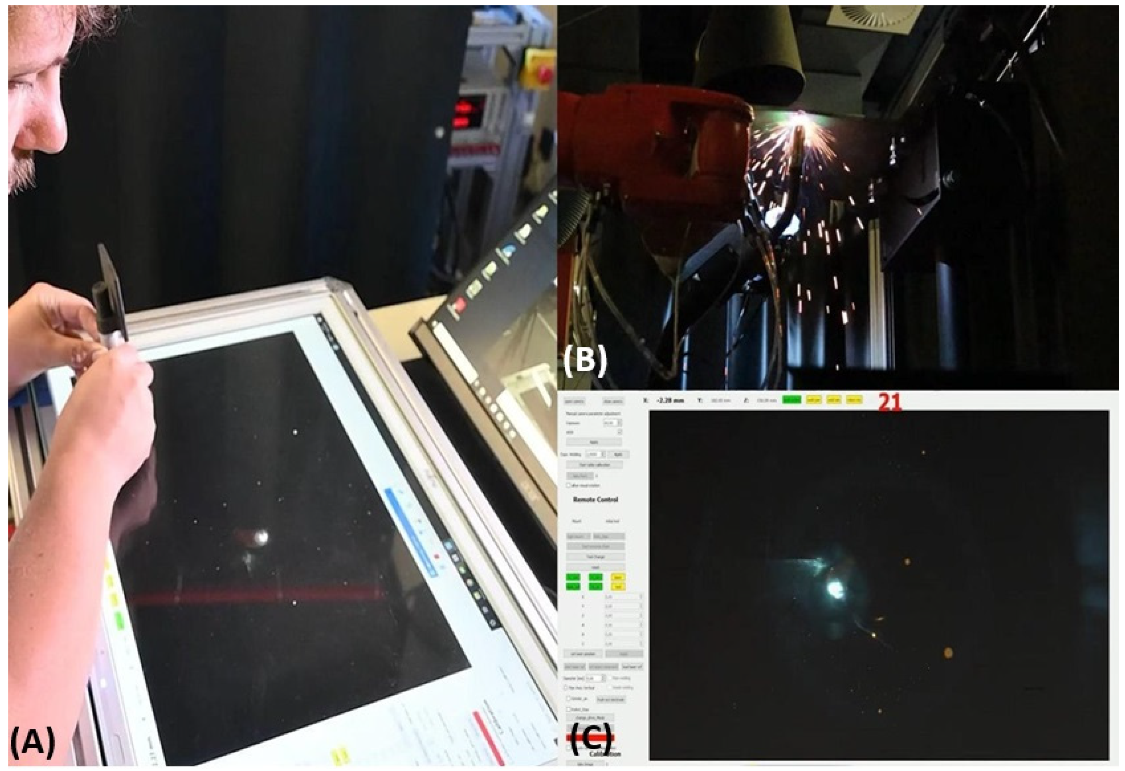
The system includes an operator workstation, visible on the left side of the screen in Figure 5. The operator sits upright and comfortably while welding on a screen in front of them, using a pen or another preferred tool in a tub-style position. This screen acts as the welding workspace, allowing the welder to use built-in features to “reach around” and reposition the welding tool at the start of the workspace without interrupting the welding process, effectively extending the working area. This is done by enabling the “ContWelding” function, which lets the system predict and continue the welder’s movement sequence—based on the previous 30 s of activity—until the operator resumes manual control. The screen also functions as a user interface, displaying all essential controls and options, shown in the bottom right of the figure. Meanwhile, the robot’s working area is depicted in the top right, where welding occurs under the coordination of the operator on the left (more on this will be explained in the next section). Thanks to the separation of the operator and working zones, the user can focus entirely on their hand movements. Additionally, the tub position and absence of heavy protective gear or welding helmets allow for unrestricted and comfortable welding postures.

2.3. Materials and Experimental Methodology

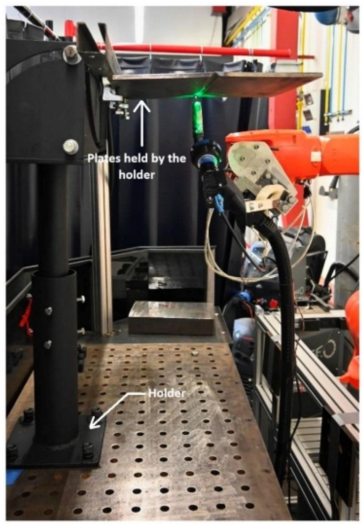
For demonstrating the weld, a perforated table was used, which was placed in the welding side of the developed system. And to weld the seams in an overhead position (OP) (see Figure 6), a sheet metal holder was constructed, which can be fixed to the perforated table. The holder is adjustable in both height and angle, and its upper plate is equipped with threads that allow the attachment of various clamps or auxiliary fixtures.
The dimensions of the test pieces used are standardized based on ISO 15614-1 [32]. It should be noted that the minimum width and length of the welded sheets must be 150 mm and 350 mm, respectively. But no minimum thickness has been specified, though both the workpiece thickness and the seam preparation of the butt joint must comply with the provisional welding instructions. S235JR + AR, a hot rolled unalloyed structural steel, was used for the tests and the steel complies with the DIN EN 10025-2 [33] standard. The designation is composed as follows:
S235 stands for the minimum yield strength of 235 MPa at room temperature.
JR indicates the impact energy of the steel which is at least 27 joules at 20 °C.
+AR means the steel is supplied “as rolled” condition without additional heat treatment [32,33].
As a shielding gas, a mixture of 18% CO2 in Argon was used and this mixture fulfills the specifications “M21” of ISO 14175 [34]. The filler material used is specified more precisely as G42 4 M21/2 C1 3Si1 in accordance with EN ISO 14341-A [35]. This is approved as a filler material for steel from S185 to S355 and can be used with the M21 shielding gas without any problems [34,35,36]. No root protection was used for the tests, and the sheets were not preheated. An iterative parameter study is performed with the developed equipment which is elaborated in the next section.

3. Parameter Study for Overhead Welding with the Developed System

3.1. Parameter Study

Initially, an iterative testing regime was adopted, to identify a set of welding parameters for the overhead seams. It must be stated here that the welding was carried out by a student at HAW as part of his master thesis without any prior knowledge on welding technology. Such an approach would further allow novices to operate the system safely while enhancing its overall user-friendliness. Based on the welding qualifications already performed for the fillet position (FP), the welding parameters were further developed for the overhead position (OP). Three test welds were performed with the adjusted parameters in order to demonstrate repeatability and these were carried out on the developed equipment. Emphasis was directed toward the fundamental parameters of wire feed and welding current, with the objective of establishing a parameter set of minimal complexity. To facilitate overhead root welding, the “cool arc Pipe” program of the Dinse welding machine was used. This program is characterized by increased wire feed at reduced welding power [37,38]. The molten metal thus becomes “colder” and is less prone to sagging due to gravity. The reduced power also allows for slower welding. To improve gas coverage in the OP, it was increased from 10 to 12 L/min.
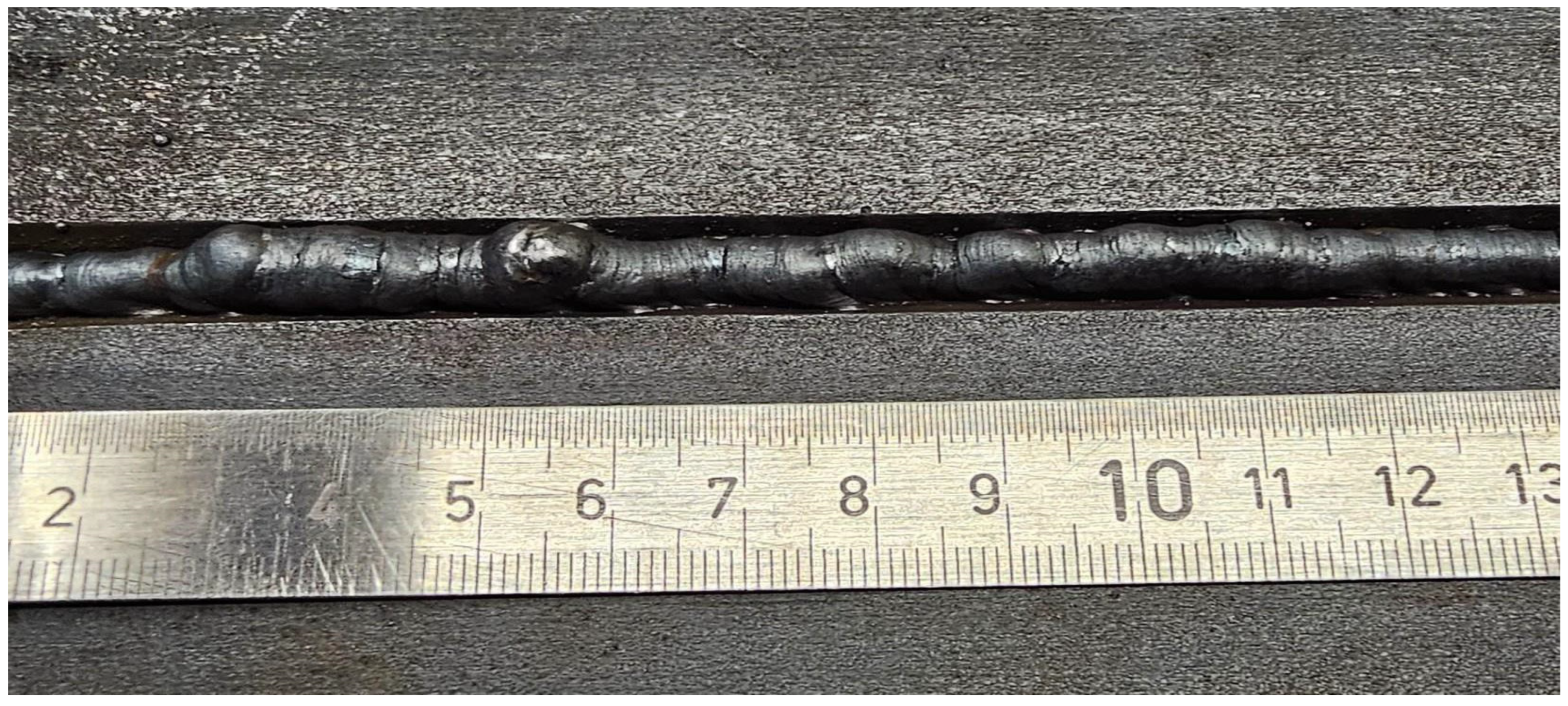
With the same wire feed rate for the trough parameters, the “cool arc Pipe” program of the welding machine reduces the current to 100 A. The voltage cannot be set manually in this program. It is calculated by the machine and adjusted automatically. The voltage for this parameter combination was 17 V. Test welds with these parameters showed insufficient root volume even at a reduced welding speed. To counteract this, the welding speed was reduced further. However, this led to a significant sagging of the root, as shown in detail in Figure 7. Additional flank bonding errors were also visible on the back of the root. In some cases, the flanks were not sufficiently melted.
In order to increase the speed and bring more heat to the sheets to be joined, the wire feed and thus the power were increased. Following the “wire feed” setting parameter, the welding machine automatically adjusts the voltage and current in the selected program. This was done in iterations of 0.5 m/min. A wire feed of 5.0 m/min showed the best results. Only one of the three test welds performed resulted in root burn-through due to excessive welding speed. At speeds above 5.5 m/min, the process became uncomfortable and hence not considered. There was increased “burn-through” of the root layer. Table 1 shows the parameters tested for the root and the irregularities observed. The selected parameters used to further develop the cover layer parameters are highlighted in green.
For cover layers, specific parameters regarding weld positioning are recommended when performing overhead welding [39]. To simplify welding of the cover layer, the power was reduced and the wire feed increased. This makes it possible to reduce the welding speed while improving control over the remote-controlled welding process. The parameter adjustments of the “Cool Arc Pipe” welding program were also used for this purpose. This welding program has hence proven to be controllable and reliable in the tests for developing the root parameters. With the same wire feed as for the root position, the parameter adjustment of the welding machine resulted in a welding current of 135 A and a voltage of 17.9 to 18.0 V. As with the root parameters examined previously, the wire feed was also adjusted by 0.5 m/min for the cover layer. Since the first parameters set did not show any irregularities under high process control, the wire feed was reduced in the first iteration. With reduced wire feed and thus reduced power, insufficient cover layer filling was observed. This resulted in flank bonding errors and continuous burn-in notches. Reducing the welding speed did not further improve the quality of the samples produced.
The next iteration increased the wire feed rate by 0.5 m/min based on the initial top layer tests. The following tests with a wire feed rate of 6.0 m/min, a voltage of 18.4 V, and a current of 140 A showed unacceptable top layer elevations. Due to the additional material introduced, the molten material sank at the selected welding speed until it came into contact with and burned into the gas nozzle. The initial parameters of the first cover layer preliminary tests proved to be the optimal cover layer parameters. Table 2 shows the cover layer parameters examined and their discernible irregularities. The cover layer parameters selected for the production of the test sheets are highlighted in green.
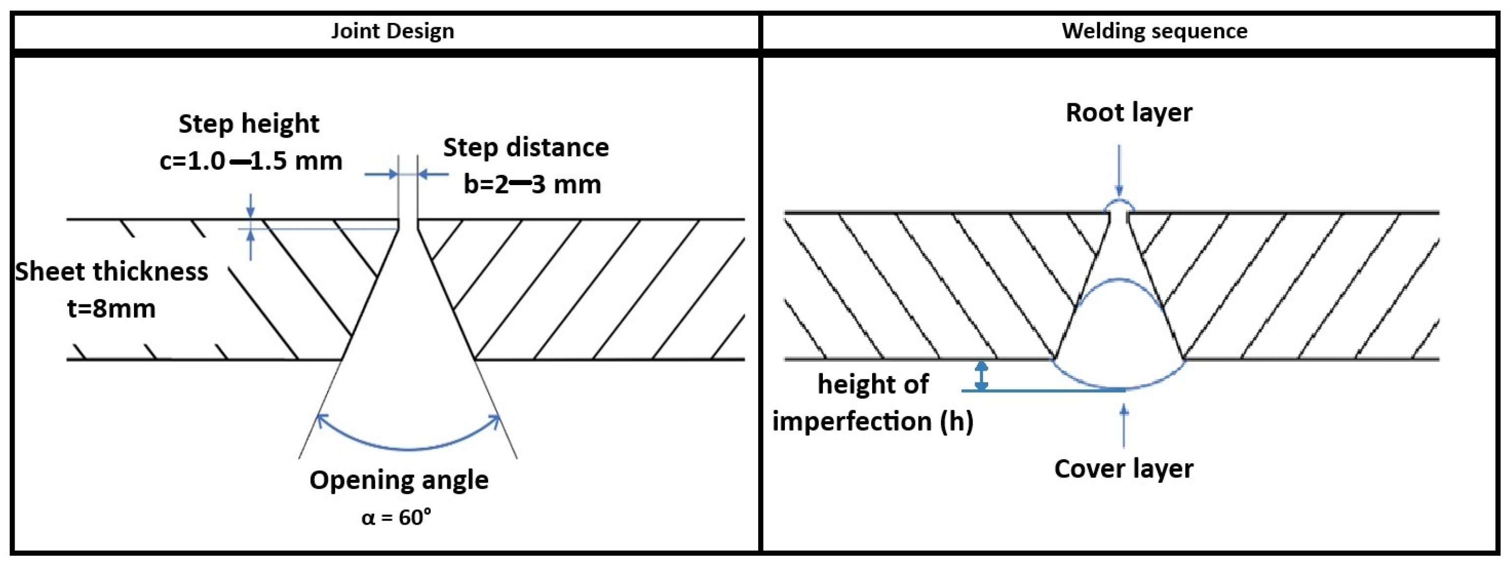
On a concluding note, from the parameter study, the adopted seam design and the determined parameters for the root and cover layers result in a set of geometry, welding sequence, and parameters shown in Figure 8 and Table 3. These were used for further study in the article.

3.2. Sample Preparation

With the parameters shown in Table 3, two plates were joined as shown in Figure 6. Initially, the root weld was performed, in such a way that the root seam was not allowed to swing out in order to avoid arc deflection and root bonding errors. In order to provide sufficient samples for the tests and to ascertain the stability of the developed system, a total of four test sheets were produced (see Figure 9).
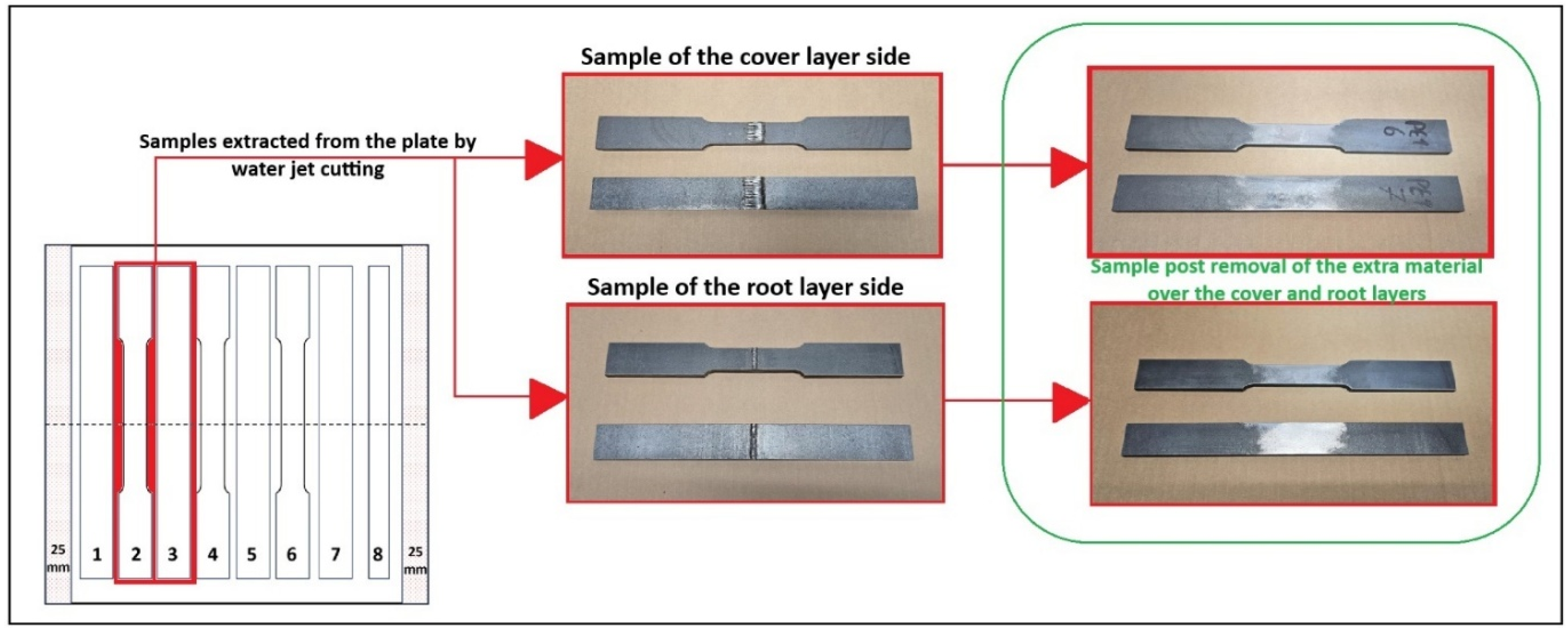
Samples for tensile, bending, micrography and hardness were from the above plates. Figure 10 shows the schematics of how the samples were extracted from the plates. All the samples were waterjet cut to precision, where there were 2 samples for tensile tests, 3 for bending tests, and a strip (shown as 8 in the figure below) for hardness testing. The weld seams on the samples were removed based on Section 6.5.4 of ISO 4136 and Section 6.6.1 of ISO 5173 [40,41]. The removal was carried out in such a way as to avoid any risk arising from the material characteristic change due to temperature effects. For this purpose, the temperature was constantly monitored during the machining operation. Care was also taken to produce a smoother surface without deep scratches, which would distort the results.

4. Results and Discussion

4.1. Weld Geometry Examination and Comparison with the Quality Norms

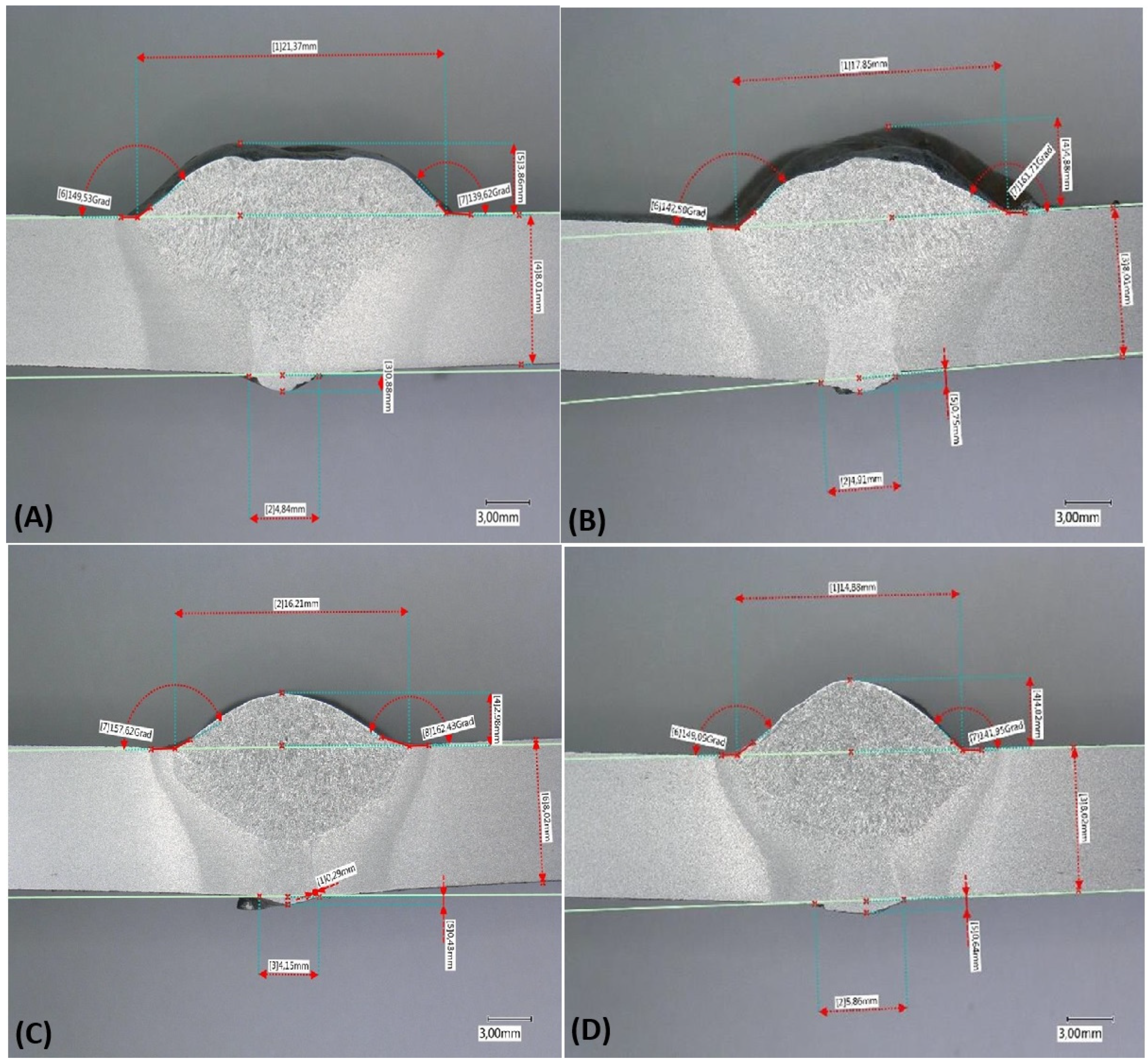
First, the microstructure of the joints was examined. The scope of testing defined in ISO 15614 [32] includes both macroscopic and microscopic examinations. The purpose of testing is to detect internal defects such as pores, pore clusters, cavities, inclusions, hot or cold cracks, and internal bonding defects. Etching can also be used to reveal and examine the heat-affected zone [42]. The strips taken from the test plates were shortened beforehand for ease of handling. The samples for macroscopy were prepared in accordance with ISO 17639:2022-05 [42]. The samples were also evaluated in accordance with the specifications of ISO 5817 [43]. In order to detect internal irregularities, the respective samples were photographed with digital microscope at eight-times magnification. The photographs taken clearly show the seam structure. Due to the etching of the surface, the heat-affected zone can be seen as a dark discolored area next to the weld seam. Figure 11 illustrates the flawless seam structure and the uniformly distinct heat-affected zone across all joints. From Figure 11, the seam geometry was ascertained and measured parameters are highlighted in Table 4. The geometry must adhere to the quality norms stated in ISO 5817, and more specifically to the ones related to “excess penetration” and “excess weld metal” in this case. For both the scenarios, the calculations are as shown below:
  • Case 1. Excess penetration for plates with thickness greater than 3 mm.
    Highest category “B”: h ≤ 1 mm + 0.2b, but max. 3 mm
    Middle category “C”: h ≤ 1 mm + 0.6b, but max. 4 mm
    Lowest category “D”: h ≤ 1 mm + 1.0b, but max. 5 mm
  • Case 2. Excess weld metal for plates with thickness greater than 3 mm.
    Highest category “B”: h ≤ 1 mm + 0.1b, but max. 5 mm
    Middle category “C”: h ≤ 1 mm + 0.15b, but max. 7 mm
    Lowest category “D”: h ≤ 1 mm + 0.25b, but max. 10 mm
In the formulas, the parameter b corresponds to the width of the weld reinforcement, whereas h represents the height of the imperfection. The results of the calculations are presented in Table 4. It is evident from the table that the root layer (Case 1) meets the strictest quality requirement, classified as level B. For the cover layer, only sample PE1 achieved level B, while the remaining plates were rated as level C. Nevertheless, the developed equipment consistently produced welds that met or exceeded level C. With further operation by a skilled welding specialist, the welds are expected to meet the highest quality levels defined by the standard [43]. The following section is devoted to the mechanical testing of samples from the four plates to provide deeper insights into the weld quality.

4.2. Mechanical Characterization

4.2.1. Tensile Test

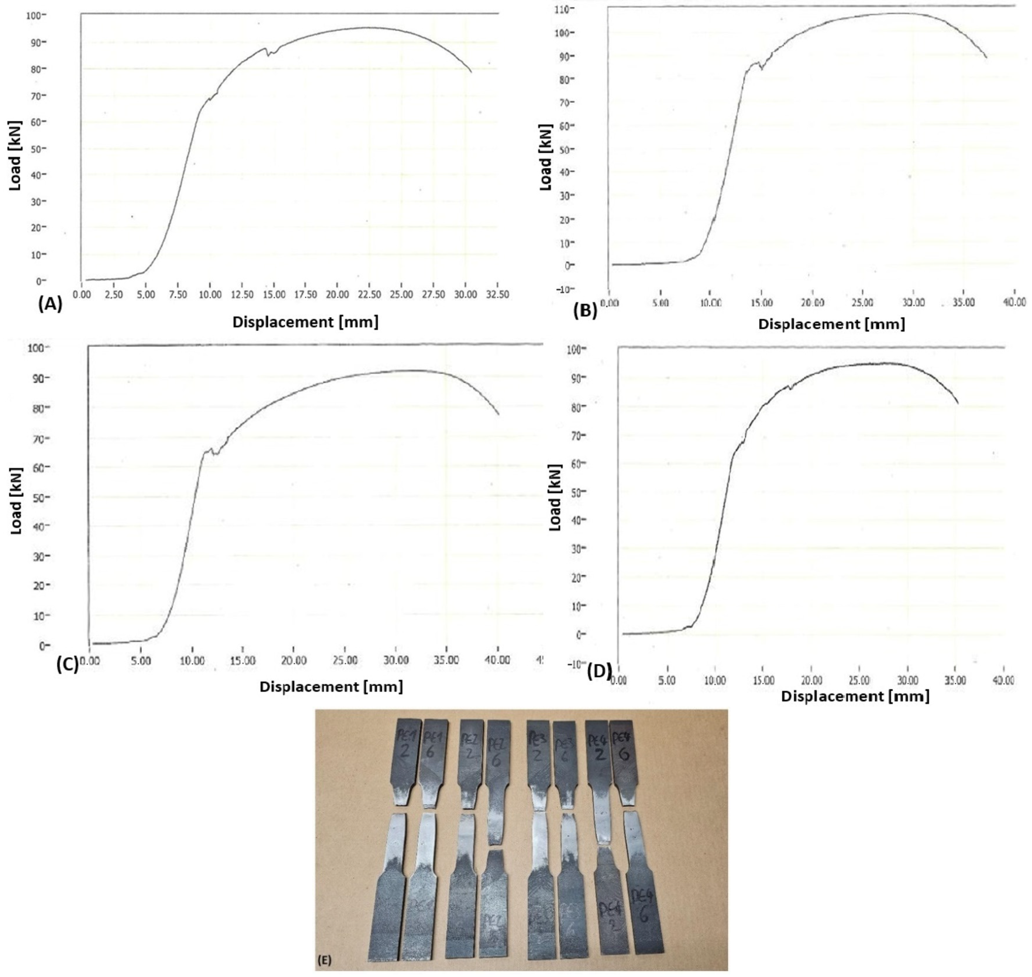
Transverse tensile tests on the samples were performed in accordance with ISO 4136:2022-09 [40]. The norm describes tensile tests specifically for weld samples, and is mainly used to determine the tensile strength “Rm” and the location of failure. The tensile strength should not fall below that of the base material, and fracture should not occur within the weld seam [43,44]. The sample preparation and the resulting dimensions were carried out as per the norm, and the dimensions can be seen in Table 2 of ISO 4136:2022-09. ISO 4136 specifies only the special features of the test, while referring to ISO 6892 [44] for details such as testing speed and other specific procedures. The resultant load–displacement curve is shown in Figure 12, where each of the four curves are linked to each of the four plates, as the results obtained were similar without much deviation. The mechanical properties of all the tested samples are shown in Table 5. As previously noted, the tensile strength of the weld samples must not be lower than that of the corresponding base material specimens. The base material in this case (S235JR + AR) has a minimum tensile strength of 360 MPa [45], and the actual strength comparisons after the tensile tests are shown in Table 5. As shown in Figure 12E, all samples failed in base material. The measured strengths are closely aligned within the range that reflects the characteristics of the base material.

4.2.2. Bending and Hardness Tests

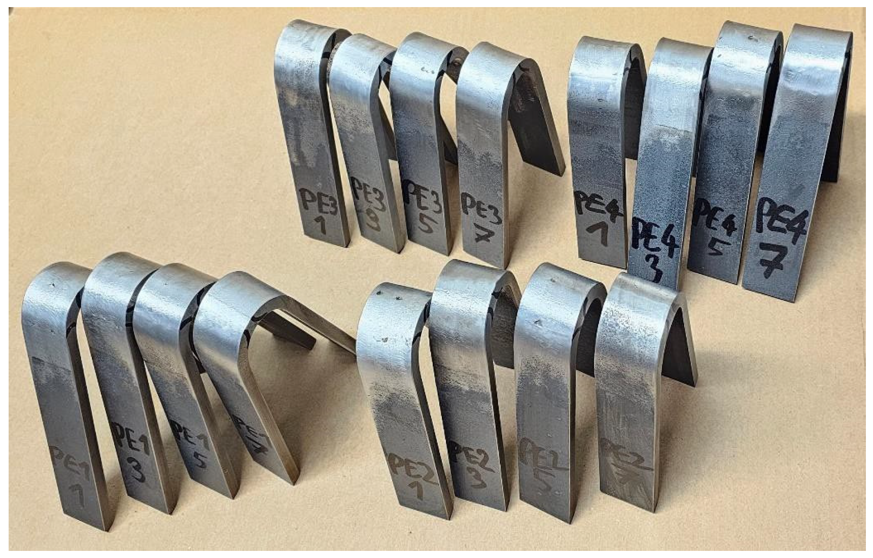
The bending tests were conducted in accordance with ISO 5173 [41]. From each of the four plates, four specimens were bent to a maximum angle of 180°. None of the specimens exhibited failure, as illustrated in Figure 13. Table 6 summarizes the details of the tested specimens together with the corresponding remarks.
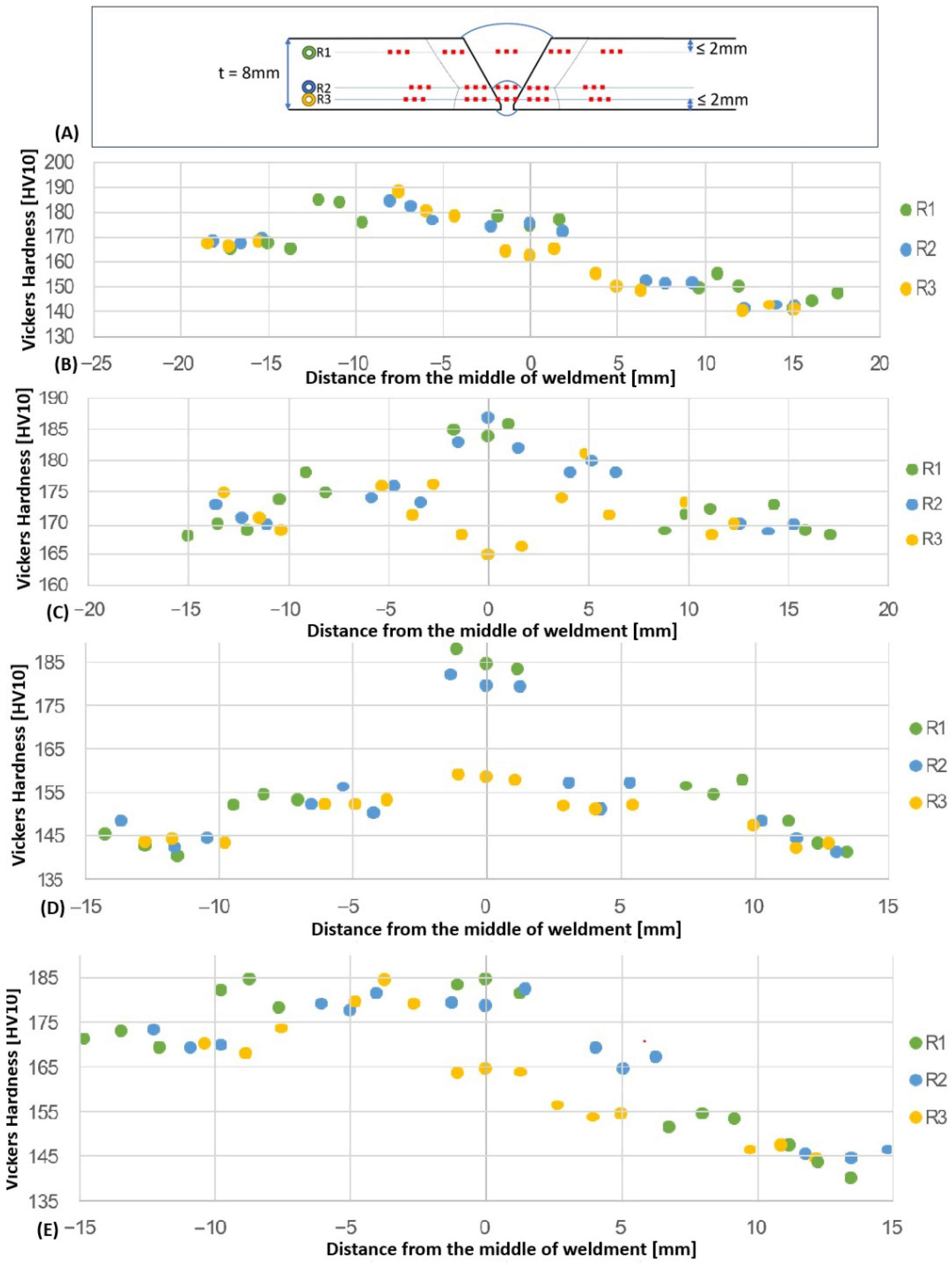
The hardness test according to ISO 9015-1 [46] showed no critical hardening of the samples. All tested sample sheets were well below the critical value of 380 HV10 defined in ISO 15614-1 [32]. The hardness impressions of the base material indicate that the sheets originated from different batches. Four of the welded sheets exhibited an average hardness of 170 HV10, whereas the other four showed a lower average hardness of 144 HV10. In the composite sheets from the first batch (170 HV10), the hardness values of the weld seam and the heat-affected zone (HAZ) differ only slightly. Due to the heat treatment of the cover layer, the root layer consistently displayed the lowest hardness values across all samples. Figure 14 presents the hardness profiles relative to the distance from the weld seam center for all specimens. As seen in Figure 14B,E, differences in hardness appear when welding sheets from two different batches, with the values on the right-hand side being lower than those on the left.
No significant deviations in hardness were observed. According to ISO 15614-1, the maximum permissible hardness for a welded joint in unalloyed, non-heat-treated structural steel is 380 HV10 [32,47,48]. The samples produced in this study exhibited a maximum hardness of 189 HV10 in the HAZ, adjacent to the harder base material. Consequently, all the samples in the hardness test in accordance with ISO 9015-1 were considered to have “passed”.

4.2.3. Comparison with Hand-Welded (Overhead) Samples

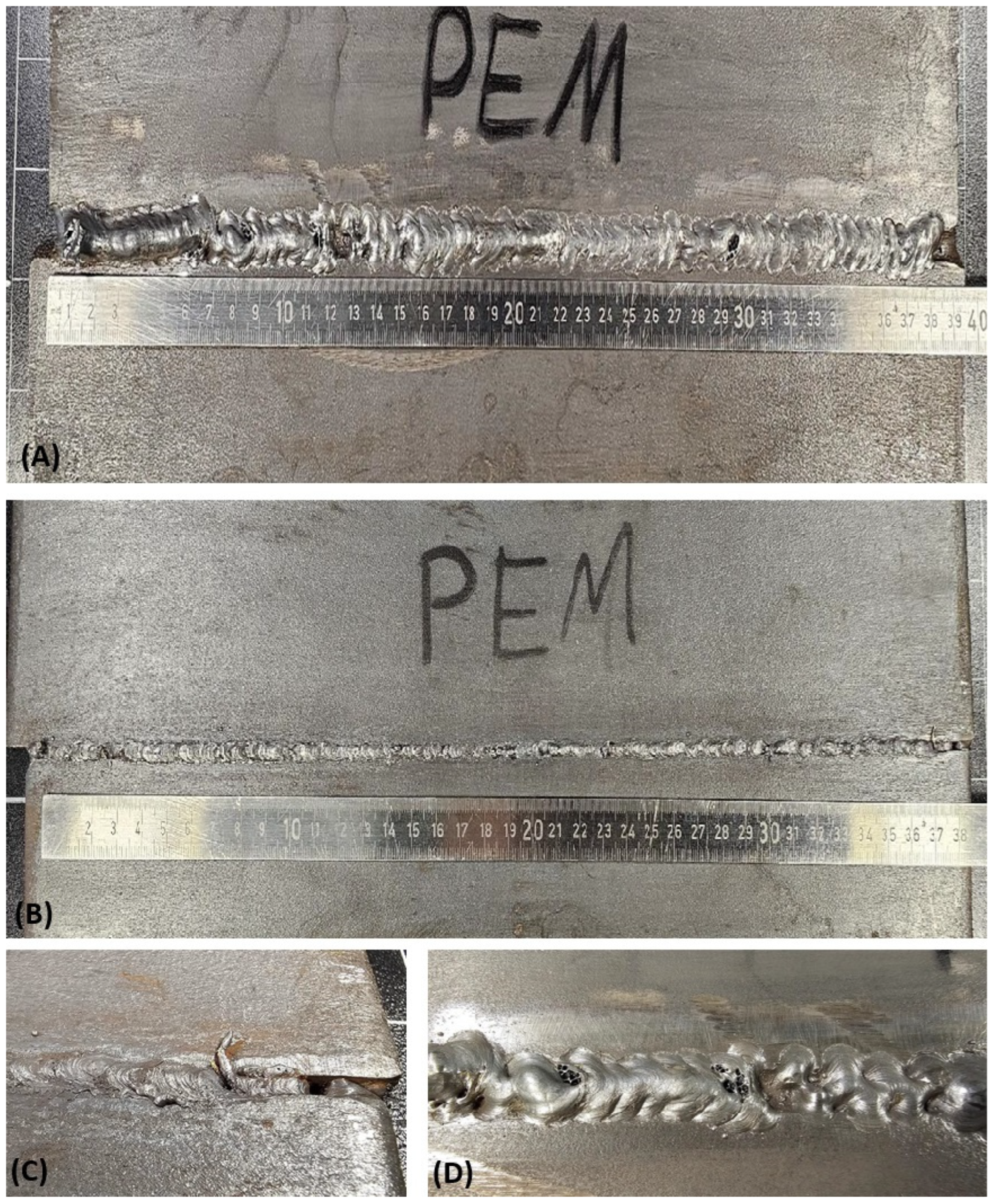
To adequately assess the results of the MeRItec project in generating overhead welds, it is useful to compare them with a manually produced overhead seam created by the same welder using identical parameters. Given the welder’s limited practical experience and training, an additional comparison can also be made with respect to the ergonomics and handling of the MeRItec system.
The overhead position is generally regarded as the most challenging welding position in terms of both required skill and ergonomics. Owing to restricted accessibility and the presence of the molten pool above the welder, it is classified as a forced position [44,45]. Although correctly set parameters support the production of flawless seams, welding in this constrained position presents additional challenges, including restricted visibility, the effect of gravity pulling molten material from the joint, postural and ergonomic strain, and exposure to descending sparks [49,50]. It is therefore essential for trained welders in constrained positions to maintain their composure when distracted by heat and sparks. This can already present a challenge for untrained individuals. Frequent welding in overhead (forced) positions is ergonomically challenging. In the long term, the physical strain on many welders leads to musculoskeletal disorders such as back injuries, bursitis, tendonitis and tendon sheath inflammation, carpal tunnel syndrome or thoracic outlet syndrome. These disorders frequently cause pain and can temporarily disable welders [49,50].
Owing to limited practical experience and training, the welder was unable to produce acceptable weld seams in the overhead position. After repeated attempts, the ergonomic challenges led the welder to discontinue the operation, resulting in the welded seams shown in Figure 15A,B. Further elaborating on the quality of the weld, limited visibility in the root area led to an increased penetration of the welding filler wire, as can be seen in Figure 15C. Furthermore, insufficient cover layer filling occurred due to incorrect positioning and repositioning during the weld process, as seen in Figure 15D.

4.3. Economic Feasibility of the Developed Equipment

To ensure a representative cost-effectiveness assessment, the topic was presented and discussed on 25 May 2018, at SLV-Nord GmbH during a TÜV Nord event attended by around 100 specialists in welding technology. The participants placed particular emphasis on health protection. Typical components discussed included vessels and silos for new construction, ship section bulkheads, pipelines, and offshore platforms. The cost-effectiveness analysis was carried out based on specific calculations. The defined boundary conditions (such as sheet thickness, weld length, material, and process) have a significant influence on manufacturing costs. For the calculation, the following manufacturing steps were taken into account:
  • Process step 1: Preparation of workstation, which includes the following:
    • Set up the workstation and arrangements for cross transport of materials.
    • Check the connection ends for roundness and angular accuracy and rework them if necessary.
    • Prepare the weld edges (weld seam preparation).
  • Process step 2: Welding
    • Welding the root pass.
    • Cleaning the seam and removing tacks (grinding).
    • Check the interpass temperature.
    • Visually inspect the seam for surface defects.
  • Process step 3: Post-processing
    • Sanding and cleaning the seam.
    • Quality control.
    • Acceptance (with documentation).
    • Clean-up of the work area.
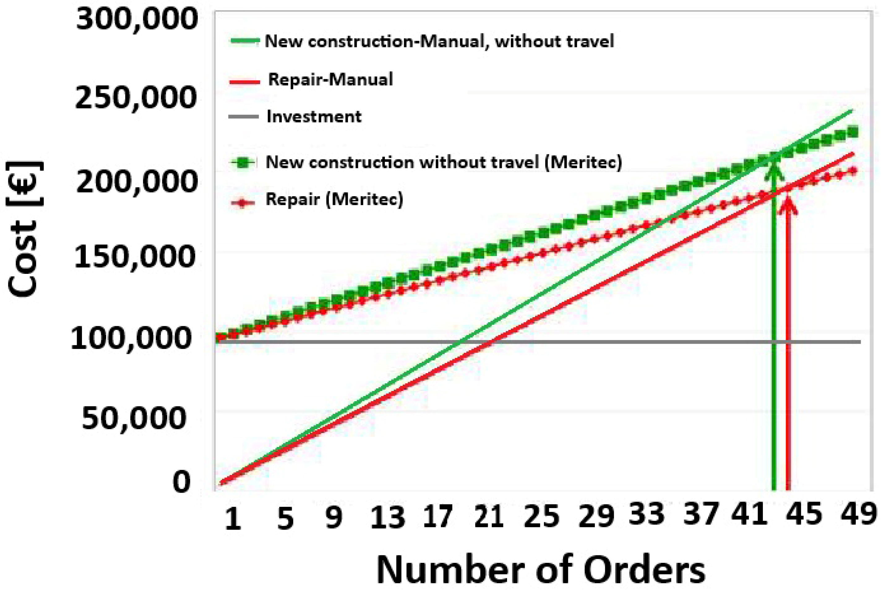
Thus, after taking into account the above three processes, the final cost of the system is approximately €94,000. The price includes the price of the KUKA robot, which is €55,000, price of the power source (€10,000), and approx. €10,000 for sensors and allied accessories. If the system is used with a real-life replica, a second power source must be provided. The cost advantage of the system is illustrated in Figure 16, where the respective break-even points are marked with arrows. For a comparable new build, as illustrated from the figure below, the break-even point will be reached after the 44th order. In the case of a repair, 45 orders are required to amortize the investment. The investment cost would be amortized in the first year for Hamburg-based companies.
For the successful market launch, it is essential to present the equipment on various platforms. For this purpose, the product will be presented at various national and international trade fairs and conferences, and the product will also be used in training courses at Hamburg University of Applied Sciences (HAW) and other project partners. The system is being manufactured in Hamburg with the support of HAW. Another market that will emerge as a by-product will be adult education, where the concept is being developed in cooperation with HAW on how the system can be explained to users in a didactically meaningful way.

4.4. A Brief Proposal for Future Work

Building on the existing work, the system is being upgraded with innovative sensors that simultaneously capture human and environmental boundary conditions. The collected data will be used to train algorithms both in real time and offline, ensuring consistent weld quality and improving process reliability. In addition, the integration of weld pool monitoring and complementary sensors enables live tracking of the weld pool, allowing early detection and notification of seam defects to the operator. To support this, a user-friendly feedback interface is being developed alongside the equipment. The study considers several sensor systems, including a laser sensor for maintaining the optimal distance between the welding torch and substrates, as well as humidity and temperature sensors. Furthermore, an advanced thermal camera from Xiris will provide live weld pool imaging during the welding process.

5. Conclusions

The article presents the results of a project focused on developing a safer and healthier working environment for older workers, particularly in welding, by employing augmented reality to enable remote operations. To achieve this, a remotely controlled human–robot welding setup was created. In this setup, the welder’s torch movements during a typical task were tracked using a stereoscopic sensor system. Any discrepancies between the welder’s hand movements and the robot arm were eliminated, allowing for precise and real-time replication of the welder’s motions.
Using the system, two standardized sheet metal pieces were welded together in an overhead position. Specific parameters for this position were developed, and the resulting welds were evaluated for quality, with the following conclusions:
  • The weld geometry was analysed for excessive penetration and weld metal. According to ISO 5817, excess penetration met the highest quality standard (Level B), while excess weld metal met the next level (Level C), indicating compliance with quality norms.
  • Tensile strength tests yielded an average of 494 MPa, surpassing the base material’s minimum requirement of 360 MPa. All test samples fractured in the base material rather than the weld seam, further demonstrating the strength of the welds.
  • Bending tests showed that the seams withstood a 180° bend without any damage.
  • Hardness testing revealed variations in the base material due to differences in batches. However, the average hardness in the heat-affected zone (HAZ) of the weld seam was 189 HV, which meets the ISO 9015-1 standard.
  • The developed system was compared to welds produced manually by the user. It was observed that, after some time, the user was affected by the ergonomic challenges, which in turn impacted the resulting weld quality. The MeRItec system therefore represents a significant improvement in workplace ergonomics for welders. It enables operators with no prior manual experience to produce weld seams that meet acceptance criteria. Nevertheless, operators must still become familiar with the system and receive appropriate training to use it effectively.
In conclusion, the developed system not only ensures a safer work environment for welding professionals but also produces welds that meet industry standards. It is currently being tested in hazardous areas/environments, allowing operators to remain at a safe distance and demonstrating the system’s suitability for real-time industrial applications.

Author Contributions

S.S.: head of the project/institute, wrote initial version of the draft reviewed the article along with editing it, provided the equipment and software for obtaining results, and oversaw the entire project, visualization and funding acquisition. S.P.S.: wrote the initial and final version of the draft and was responsible for data analysis. R.L.: performed the conceptualization and methodology and data analysis. L.C.E.: Conceptualization, software and validation. E.M.: wrote the initial and final version of the draft and was responsible for data analysis. P.Z.: Conceptualization, software, validation. J.M.: Methodology, software, visualization, funding acquisition. All authors have read and agreed to the published version of the manuscript.

Funding

This research was funded by the Hamburgerische Investitions-und Förderbank (IFB Hamburg) within the scope of the European Regional Development Fund, grant number 51086029. We acknowledge support for the article processing charge by the Open Access Publication Fund of Hamburg University of Applied Sciences.

Data Availability Statement

The original contributions presented in this study are included in the article. Further inquiries can be directed to the corresponding authors.

Conflicts of Interest

The authors declare no conflict of interest.

References

  1. Staubli, S.; Zweimüller, J. Does raising the retirement age increase employment of older workers? J. Public Econ. 2013, 108, 17–32. [Google Scholar] [CrossRef] [PubMed]
  2. European Commission. The 2012 Ageing Report: Economic and Budgetary Projections for the 27 EU Member States (2010–2060); Directorate-General for Economic and Financial Affairs: Brussels, Belgium, 2012; ISBN 978-92-79-22850-6. [Google Scholar] [CrossRef]
  3. Bhumika, N.; Prabhu, G.V.; Ferreira, A.M.; Kulkarni, M.K.; Vaz, F.S.; Singh, Z. Respiratory Morbidity Among Welders in the Shipbuilding Industry, Goa. Indian J. Occup. Environ. Med. 2012, 16, 63–65. [Google Scholar] [CrossRef] [PubMed]
  4. Ozdemir, O.; Numanoglu, N.; Gonullu, U.; Savas, I.; Alper, D.; Gurses, H. Chronic Effects of Welding Exposure on Pulmonary Function Tests and Respiratory Symptoms. Occup. Environ Med. 1995, 52, 800–803. [Google Scholar] [CrossRef] [PubMed]
  5. European Agency for Safety and Health at Work. The Value of Occupational Safety and Health and the Societal Costs of Work-Related Injuries and Diseases; Publications Office of the European Union: Luxembourg, 2019. [Google Scholar] [CrossRef]
  6. Ajoudani, A.; Albrecht, P.; Bianchi, M.; Cherubini, A.; Del Ferraro, S.; Fraisse, P.; Fritzsche, L.; Garabini, M.; Ranavolo, A.; Rosen, P.H.; et al. Smart Collaborative Systems for Enabling Flexible and Ergonomic Work Practices. IEEE Robot. Autom. Mag. 2020, 27, 169–176. [Google Scholar] [CrossRef]
  7. Lopes, D.R.; Schmitz, A.; Lenzi, A.R.; Catai, E.R.; Gadda, T.M.C. Simulation of Exposure to Metal Fumes in the SMAW Welding Process Using IH MOD 2.0: Occupational Health and Safety Assessment. Rev. Gest. Soc. Ambient. 2018, 18, e010362. [Google Scholar] [CrossRef]
  8. Islam, K.S.; Hossain, A.; Khan, M.R.; Islam, M.T. The Role of Age in Shaping Risk-Taking Behaviours and Safety Awareness in the Manufacturing Sector. Am. J. Adv. Technol. Eng. Solut. 2018, 1, 98–121. [Google Scholar] [CrossRef]
  9. Griffiths, A. Differential Health Effects of Work Organization by Age. In Occupational and Environmental Health: Recognizing and Preventing Disease and Injury, 6th ed.; Levy, B.S., Wegman, D.H., Baron, S.L., Sokas, R.K., Eds.; Oxford University Press: Oxford, UK, 2014; pp. 199–200. Available online: https://www.ncbi.nlm.nih.gov/books/NBK207715/ (accessed on 19 July 2025).
  10. Götz, S.; Hoven, H.; Müller, A.; Dragano, N.; Wahrendorf, M. Age Differences in the Association between Stressful Work and Sickness Absence among Full-Time Employed Workers: Evidence from the German Socio-Economic Panel. Int. Arch. Occup. Environ. Health 2018, 91, 479–496. [Google Scholar] [CrossRef] [PubMed]
  11. Frese, M.; Mohr, G. Prolonged Unemployment and Depression in Older Workers: A Longitudinal Study of Intervening Variables. Soc. Sci. Med. 1987, 25, 173–178. [Google Scholar] [CrossRef] [PubMed]
  12. Pfeil, S.; Holtz, K.; Kopf, K.A.; Hegerl, U.; Rummel-Kluge, C. Minor Depression in Older, Long-Term Unemployed People Seeking Vocational Support. BMC Psychiatry 2017, 17, 243. [Google Scholar] [CrossRef] [PubMed]
  13. Okunribido, O.; Wynn, T. Ageing and Work-Related Musculoskeletal Disorders: A Review of the Recent Literature; Research Report 779; Health and Safety Executive: Sudbury, UK, 2010. [Google Scholar]
  14. Plouvier, S.; Gourmelen, J.; Chastang, J.-F.; Lanoë, J.-L.; Leclerc, A. Low Back Pain Around Retirement Age and Physical Occupational Exposure during Working Life. BMC Public Health 2011, 11, 268. [Google Scholar] [CrossRef] [PubMed]
  15. Yeomans, L. An Update of the Literature on Age and Employment; Research Report RR832; Health and Safety Executive: Sudbury, UK, 2011. Available online: http://www.hse.gov.uk/research/rrpdf/rr832.pdf (accessed on 19 July 2025).
  16. Ilmarinen, J.E. Aging Workers. Occup. Environ. Med. 2001, 58, 546. [Google Scholar] [CrossRef] [PubMed]
  17. Ilmarinen, J. Ageing Workers in Finland and in the European Union: Their Situation and the Promotion of the Working Ability, Employability and Employment. Geneva Pap. Risk Insur. 2001, 26, 623–641. [Google Scholar] [CrossRef]
  18. Ilmarinen, J.; European Agency for Safety and Health at Work. Promoting Active Ageing in the Workplace. EU-OSHA. 2025. Available online: https://osha.europa.eu/en/publications/promoting-active-ageing-workplace (accessed on 19 July 2025).
  19. Sigma Ergonomics. Available online: https://www.sigmaoffice.gr/en/ergonomics/ (accessed on 11 July 2025).
  20. Liebers, F.; Caffier, G. Berufsspezifische Arbeitsunfähigkeit Durch Muskel-Skelett-Erkrankungen in Deutschland; Bundesanstalt für Arbeitsschutz und Arbeitsmedizin: Dortmund, Germany, 2009. [Google Scholar]
  21. Wang, Q.; Jiao, W.; Wang, P.; Zhang, Y. Digital Twin for Human-Robot Interactive Welding and Welder Behavior Analysis. IEEE/CAA J. Autom. Sinica 2021, 8, 334–343. [Google Scholar] [CrossRef]
  22. Lee, D.; Han, K. Vision-based construction robot for real-time automated welding with human-robot interaction. Autom. Constr. 2024, 168, 105782. [Google Scholar] [CrossRef]
  23. Zhao, M.; Liu, X.; Wang, K.; Liu, Z.; Dong, Q.; Wang, P.; Su, Y. Welding Seam Tracking and Inspection Robot Based on Improved YOLOv8s-Seg Model. Sensors 2024, 24, 4690. [Google Scholar] [CrossRef] [PubMed]
  24. Kumar, R.; Pal, R.; Singh, P.; Mohan, D. Occupational Hazard Exposure and General Health Profile of Welders in Rural Delhi. Indian J. Occup. Environ. Med. 2014, 18, 85–89. Available online: https://www.ncbi.nlm.nih.gov/pmc/articles/PMC4083517/ (accessed on 19 July 2025). [PubMed]
  25. Riccelli, M.G.; Goldoni, M.; Poli, D.; Mozzoni, P.; Cavallo, D.; Corradi, M. Welding Fumes, a Risk Factor for Lung Diseases, Chronic Obstructive Pulmonary Disease and Cancer. Int. J. Environ. Res. Public Health 2020, 17, 2552. [Google Scholar] [CrossRef] [PubMed]
  26. Sun, Y.; Zhang, W.J.; Zhang, Y.M. Mixed Reality Augmented Remote Welding System with Virtual Fixtures and Autonomous Agents. In Proceedings of the 2024 4th International Conference on Robot Control Engineering (ICRCE), Edinburgh, UK, 27–29 June 2024; pp. 131–137. [Google Scholar]
  27. Chan, W.P.; Hanks, G.; Sakr, M.; Zhang, H.; Zuo, T.; Van der Loos, H.M.; Croft, E. Design and Evaluation of an Augmented Reality Head-Mounted Display Interface for Human Robot Teams Collaborating in Physically Shared Manufacturing Tasks. ACM Trans. Hum.-Robot. Interact. (THRI) 2022, 11, 1–19. [Google Scholar]
  28. Ebel, L.C.; Zuther, P.; Maass, J.; Sheikhi, S. Motion Signal Processing for a Remote Gas Metal. Robotics 2020, 9, 30. [Google Scholar] [CrossRef]
  29. Ebel, L.C.; Maass, J.; Zuther, P.; Sheikhi, S. Trajectory Extrapolation for Manual Robot Remote Welding. Robotics 2021, 10, 77. [Google Scholar] [CrossRef]
  30. KUKA Aktiengesellschaft. Available online: https://www.kuka.com/en-gb/services/downloads?terms=Language:en:1 (accessed on 15 March 2020).
  31. Fronius USA LLC. Available online: https://www.fronius.com/en-us/usa (accessed on 15 March 2020).
  32. ISO 15614-1:2017; Specification and Qualification of Welding Procedures for Metallic Materials—Welding Procedure Test—Part 1: Arc and Gas Welding of Steels and Arc Welding of Nickel and Nickel Alloys. International Organization for Standardization: Geneva, Switzerland, 2017.
  33. DIN EN 10025-2:2019; Hot Rolled Products of Structural Steels—Part 2: Technical Delivery Conditions for Non-Alloy Structural Steels. Deutsches Institut für Normung: Berlin, Germany, 2019.
  34. DIN EN ISO 14175; Schweißzusätze: Gase und Mischgase für das Lichtbogenschweißen und Verwandte Prozesse. Beuth Verlag GmbH: Berlin, Germany, 2008.
  35. DIN EN ISO 14341; Schweißzusätze: Drahtelektroden und Schweißgut zum Metall-Schutzgasschweißen von Unlegierten Stählen und Feinkornstählen. Beuth Verlag GmbH: Berlin, Germany, 2020.
  36. weldingtool.eu. MAG-Schweißdraht G3Si1 HOT WELD M Ø 1.2 mm, Lagengespult Nach EN ISO 14341-A-G42 4-M21 2-C1 3Si1. Available online: https://www.weldingtool.eu/mag-schweissdraht-g3si1-hot-weld-m-o-1-2-mm-lagengespult-nach-en-iso-1434i-a-g42-4-m21-2-c1-3si1.html (accessed on 16 January 2024).
  37. DINSE GmbH. DINSE DIX PI 3006.M I—Operation Manual; DINSE GmbH: Hamburg, Germany, 2018. [Google Scholar]
  38. DINSE GmbH. DINSE DIX PI 3006.M I—Programmübersicht; DINSE GmbH: Hamburg, Germany, 2018. [Google Scholar]
  39. DVS. Internationaler Schweißfachingenieur Teil III—Skript; DVS: Düsseldorf, Germany, 2019. [Google Scholar]
  40. ISO 4136:2022; Destructive Tests on Welds in Metallic Materials: Transverse Tensile Test. International Organization for Standardization: Geneva, Switzerland, 2022.
  41. ISO 5173:2023; Destructive Tests on Welds in Metallic Materials: Bend Tests. International Organization for Standardization: Geneva, Switzerland, 2023.
  42. ISO 17639:2022; Destructive Tests on Welds in Metallic Materials: Macroscopic and Microscopic Examination of Welds. International Organization for Standardization: Geneva, Switzerland, 2022.
  43. ISO 5817:2014; Welding: Fusion-Welded Joints in Steel, Nickel, Titanium and Their Alloys (Beam Welding Excluded): Quality Levels for Imperfections. International Organization for Standardization: Geneva, Switzerland, 2014.
  44. DIN EN ISO 6892-1:2020; Metallische Werkstoffe: Zugversuch—Teil 1: Prüfverfahren bei Raumtemperatur. Beuth Verlag GmbH: Berlin, Germany, 2020.
  45. Arthur Weber. Stahlblech Band—S235JR+AR. Available online: https://www.arthurweber.ch/wp2021/wp-content/uploads/2022/08/Materialdatenblatt-Stahlblech-Band-%E2%80%93-S235JRAR.pdf (accessed on 17 January 2024).
  46. ISO 9015-1:2011; Destructive Tests on Welds in Metallic Materials: Hardness Testing—Part 1: Hardness Test on Arc Welded Joints. International Organization for Standardization: Geneva, Switzerland, 2011.
  47. ESAB Welding & Cutting GmbH. Die 4 Wichtigsten Arten von Schweißpositionen. Available online: https://esab.com/de/eur_de/esab-university/blogs/4-main-types-of-welding-positions/ (accessed on 1 February 2024).
  48. TECHNOLIT GmbH. Überblick der Wichtigsten Schweißpositionen Nach DIN EN ISO 6947. Available online: https://schweisstechnik.technolit.de/schweisstechnik-wissen/richtig-schweissen-basiswissen/schweisspositionen/ (accessed on 3 February 2024).
  49. Fronius International GmbH. Ergonomisches Schweißen—Ein Paradox? DVS Media GmbH. 29 September 2023. Available online: https://www.home-of-welding.com/news/ergonomisch-schweissen-ein-paradox-3603 (accessed on 13 February 2024).
  50. KEMPER GmbH. Ergonomie Beim Schweißen: Wie Exoskelette Für Entlastung Sorgen; Arbeitsschutz Schweißen—KEMPER GmbH. Available online: https://arbeitsschutz-schweissen.de/ergonomie-beim-schweissen-wie-exoskelette-fuer-entlastung-sorgen/ (accessed on 19 July 2025).
Figure 1. (A) Cost of work-related accidents and (B) causes of work-related fatalities illnesses in the EU-28 (%) in the EU-28 [5].
Processes 13 03017 g001
Figure 2. Setup for movement tracking with a visual.
Processes 13 03017 g002
Figure 3. Process chain for remote welding.
Processes 13 03017 g003
Figure 4. Representation of the measured and extrapolated signal, (A) Displacement in Z-axis, (B) Displacement in Y-axis and (C) Displacement in YZ-axis.
Processes 13 03017 g004
Figure 5. Developed working system. (A) Workplace, (B) Overhead welding by robot and (C) Screen shot of the system.
Processes 13 03017 g005
Figure 6. Experimental setup for the overhead-welding of the plates.
Processes 13 03017 g006
Figure 7. Root sagging seen in OP preliminary tests.
Processes 13 03017 g007
Figure 8. Weld geometry showing the joint design and the weld sequence.
Processes 13 03017 g008
Figure 9. Sample plates PE1, PE2, PE3 and PE4.
Processes 13 03017 g009
Figure 10. Sample preparation from the plates.
Processes 13 03017 g010
Figure 11. Microstructure of the four plates at their respective joints along with width and height measurements, (A) PE1, (B) PE2, (C) PE3, and (D) PE4.
Processes 13 03017 g011
Figure 12. Load–displacement curves from the tested samples. (A) PE1, (B) PE2, (C) PE3, (D) PE4 and (E) Tested samples.
Processes 13 03017 g012
Figure 13. All the samples bent to 190°.
Processes 13 03017 g013
Figure 14. Hardness distribution with the base plate and the weld seam. (A) Hardness measurement methodology in the structure, (B) Hardness in PE1, (C) Hardness in PE2, (D) Hardness in PE3, and (E) Hardness in PE4.
Processes 13 03017 g014
Figure 15. Manually welded seam. (A) Top layer, (B) Root layer, (C) Wire penetration in the root and (D) Burn marks and open surface pores.
Processes 13 03017 g015
Figure 16. Amortization of the investment.
Processes 13 03017 g016
Table 1. Parameter study for the root parameters.
Test No.Wire Feed Rate
[m/min]
Weld Current
[A]
Remarks
14.017-insufficient root volume
-flank connection on the root side is sufficient
24.017.1-root sag/excessive root volume
-flank fusion defect
34.016.9-insufficient root volume
-flank connection on the root side is insufficient
44.517.2-flank fusion defect
54.517.4-insufficient root volume
-flank fusion defect
64.517.3/
75.017.5/
85.017.6-root penetration due to increased speed
95.017.5/
105.517.9-root sag/excessive root volume
-root burn-out
115.517.8-root burn-out
125.517.8-root penetration due to increased speed
136.018.3-root burn-out
-arc deflection
-flank fusion defect
Table 2. Parameter study of the cover layer parameters.
Test No.Wire Feed Rate
[m/min]
Weld Current
[A]
Remarks
15.517.9/
25.518.0/
35.517.9/
45.017.6-insufficient cover pass filling
-flank fusion defects
55.017.4/
65.517.5-insufficient cover pass filling
76.018.4-cover pass over-reinforcement
-surface open pores
86.018.3-gas nozzle sticking due to cover pass over-reinforcement
95.018.3/
Table 3. Details for the welding parameters.
Weld SequenceProcessFeed Wire Diameter [mm]Current
[A]
Voltage
[V]
Current
Type/Polarity
Wire Feed Rate [m/min]
Root1351.012517.5DC+5.0
Cover1351.013517.9DC+5.5
Table 4. Weld seam geometry measurements.
Sl. No.Cover LayerRoot LayerCase 1Case 2
b
[mm]
h [mm]b
[mm]
h [mm]Excess PenetrationCategoryExcess Weld MetalCategory
PE1223612.2B3.2B
PE218361.52.2B3.7C
PE318.53.551.52B3.775C
PE4152.5522B3.25C
Note: b is the width of the reinforcement, and h is the height of the imperfection.
Table 5. Tensile test results from all the samples.
Sl. No.Cross-Sectional Area [mm2]Tensile Strength
[MPa]
Minimal Required Tensile Strength [MPa]Max. Load [kN]Fracture Location
PE1_2201.4547136094.97BM
PE1_6199.3347436094.4BM
PE2_2192.01459360107.41BM
PE2_6195.12456360107.54BM
PE3_2197.3546536091.57BM
PE3_6198.7445736088.69BM
PE4_2193.4549236094.99BM
PE4_6196.0549136095.32BM
Note: BM base material.
Table 6. Bend test results in accordance with ISO 5173:2023 [41].
Sl. No.Thickness “ts
[mm]
Width “b”
[mm]
Sample TypeBending Angle [°]Remarks
PE1_1832TRBB180Pass, no fracture
PE1_3832TFBB180Pass, no fracture
PE1_5832TRBB180Pass, no fracture
PE1_7832TFBB180Pass, no fracture
PE2_1832TRBB180Pass, no fracture
PE2_3832TFBB180Pass, no fracture
PE2_5832TRBB180Pass, no fracture
PE2_7832TFBB180Pass, no fracture
PE3_1832TRBB180Pass, no fracture
PE3_3832TFBB180Pass, no fracture
PE3_5832TRBB180Pass, no fracture
PE3_7832TFBB180Pass, no fracture
PE4_1832TRBB180Pass, no fracture
PE4_3832TFBB180Pass, no fracture
PE4_5832TRBB180Pass, no fracture
PE4_7832TFBB180Pass, no fracture
Note: TRBB—Transverse root bend test specimen; TFBB—Transverse face bend test specimen.
Disclaimer/Publisher’s Note: The statements, opinions and data contained in all publications are solely those of the individual author(s) and contributor(s) and not of MDPI and/or the editor(s). MDPI and/or the editor(s) disclaim responsibility for any injury to people or property resulting from any ideas, methods, instructions or products referred to in the content.