Article

Design and Study of a New Rotary Jet Wellbore Washing Device

1
College of Petroleum and Natural Gas Engineering, Liaoning Petrochemical University, No. 1, West Section of Dandong Road, Wanghua District, Fushun 113001, China
2
School of Civil Engineering, Liaoning Petrochemical University, No. 1, West Section of Dandong Road, Wanghua District, Fushun 113001, China
3
College of Environmental and Safety Engineering, Liaoning Petrochemical University, No. 1, West Section of Dandong Road West Section 1, Fushun 113001, China
*
Author to whom correspondence should be addressed.
Processes 2025, 13(9), 3015; https://doi.org/10.3390/pr13093015
Submission received: 28 August 2025 / Revised: 18 September 2025 / Accepted: 19 September 2025 / Published: 21 September 2025
(This article belongs to the Section Manufacturing Processes and Systems)

Abstract

Wellbore washing technology is a basic operation in wellbore maintenance. Problems such as low automation levels, long processing times, the fact that it is easy to cause downhole falling, and cleaning blind areas greatly affect the use and maintenance of traditional cleaning equipment. These problems usually come from design defects such as a complicated installation process, a lack of an anti-impact structure, and a fixed jet direction. To address the aforementioned issues, this paper proposes an efficient and integrated rapid-disassembly and -assembly automatic filtration rotary jet cleaning device. The device is divided into two main units and further subdivided into four modules. The quick-assembly unit comprises an elastic connection module and a downstroke quick-assembly module, which can automatically compensate for deviations in equipment position during the installation process, ensuring the reliability of the installation process and the sealing of the equipment and facilitating the rapid connection and separation of the tool string. The wellbore cleaning unit includes a hydraulic rotary washing module and a rotary filtration storage module. The wellbore is jet-flushed by hydraulic drive, and the solid particles are separated and filtered during the cleaning fluid circulation process to realize the purification and reuse of the cleaning fluid. The device reduces the installation operation time and labor cost, improves the reliability of equipment in the well, improves the flushing coverage area and the cleaning efficiency, realizes the reuse of the cleaning liquid in the wellbore, reduces the energy consumption of the flowback treatment, and comprehensively improves the cleaning efficiency and the energy utilization efficiency.

1. Introduction

The maintenance effect of oil and gas wells in the process of exploration and exploitation directly affects the efficiency and energy consumption of oil and gas output and affects the economic output level of oil fields. In the process of oil and gas development, due to the influence of formation pressure, sand in the formation sometimes enters the wellbore production layer with the oil and gas flow, or it stays in the cracks in the formation, blocking the oil and gas output channel. At the same time, with the application of water injection and other recovery methods, mud and sand migration will also occur in water injection wells, reducing the effect of water injection. The sand removal and cleaning operation of oil and gas wells can effectively remove sand and other obstructions so that oil and gas can return to normal output. The traditional cleaning equipment usually carries out jet flushing through the top water hole. Because the jet axis is close to the wellbore axis, it can only remove sand that has accumulated at the bottom of the well, and the cleaning degree of the blockage adhering to or deposited on the wellbore is insufficient, and it is unable to go deep into the production layer to remove the blockage in the formation. In addition, with the application of inclined wells and horizontal wells, the law of sand accumulation in the wellbore changes, and the traditional axial jet cleaning effect is further reduced. The installation time of traditional single-well cleaning equipment is about 4–7 days, and the installation of the equipment occupies the main part of the process [1]. The cleaning coverage achieved during wellbore cleaning is between 20–60% [2]. Due to the rapid wear of traditional mechanical tools in a harsh downhole environment, a poor cleaning effect can easily lead to cutting bed accumulation, which may lead to downhole complications such as sticking, friction torque increase, etc., so the downtime in traditional cleaning operations is often more than 4 h.
Against the background of the continuous growth of energy demand and the accelerated extension of resource development to deep strata, oil and gas drilling technology, as a key means to obtain underground resources, has become increasingly prominent in its strategic position [3]. However, as the drilling depth continues to break through the 10,000 m limit, the maintenance of oil and gas wells is facing unprecedented severe challenges. The extremely high-temperature and high-pressure environment, complex and changeable geological structure, and irregular wellbore trajectory caused by long-distance strings leads to increased wear and tear of production and maintenance equipment, a significant increase in failure rate, and an exponential increase in the difficulty of remote monitoring and precise intervention [4,5,6]. Deep well operation has the characteristics of high costs and low fault tolerance, and it has been difficult to balance the core requirements of efficiency and safety using the traditional maintenance mode. How to realize equipment protection, reduce the failure rate, and improve cleaning efficiency in deep strata has become one of the bottlenecks restricting the efficiency and continuity of oil and gas resource development [7,8].
As the core link between resource exploration and exploitation, the production efficiency and reliability of oil and gas well facilities directly determine the economy and feasibility of oilfield production [9,10,11,12]. At present, significant limitations in the maintenance of oil and gas wells plague researchers and field operators and lack solutions: The connection method of different equipment cannot be used universally, the field installation and debugging period is long, and the labor and time cost are high; the jet coverage of traditional well washers is small, and the washed sediment cannot be returned in time, resulting in tool jamming, etc. [13,14,15]. Traditional cleaning equipment is connected by bolts, screw threads, and other connecting pieces, which are prone to failure in downhole working conditions, such as bolt fracture failure, screw thread failure, etc. Once they occur, they will form downhole falling objects, and in serious cases, they will cause wellbore abandonment and other risks. These problems are particularly prominent in deep wells, ultra-deep wells, and complex geological conditions, which not only significantly prolong the non-production time but also greatly increase the risk of downhole accidents.
In order to solve the above problems, domestic and foreign scholars have conducted research and designed methods to solve this. Huang [16] et al. designed a calculation model for a hydrogen-blending natural gas pipeline package and determined that the change in throughput has a direct relationship with the pipeline pressure, thus affecting the structural design of the fluid pipeline and cleaning equipment. Therefore, it can be concluded that adjusting reserves by changing the inlet pressure is effective. Shao [17] et al. developed a circulating well washing device and formulated matching technology to solve the problems of a high pump inspection operation ratio caused by coal dust and sand deposition, which can effectively improve the liquid flow velocity in tubing, carry sand and coal dust in the tubing to the ground, solve pump blockages and pump leakages, and reduce operation cost. However, this technology has only been tested in coalbed methane development and lacks specificity for oil well cleaning, and there are more viscous and difficult-to-remove attachments in oil wells, such as asphaltene and wax, which bring limitations for this technology. Based on the development of traditional well washing technology, Ji Yukun [18] synthesized the performance advantages of low-density well washing fluid and vaporization well washing technology and designed a reservoir plugging removal and well washing technology, which can effectively solve the plugging problem in the near-well zone of low-density oilfields, protect the reservoir from foreign material pollution, and thus improve the production of the oilfield. However, the limitation of low-density fluids increases the difficulty of pressure control, and proprietary fluid formulations incur additional operating costs, and thus, the technology lacks the potential for universal application. Table 1 summarizes the relevant patents for the design of wellbore cleaning devices at home and abroad. However, there is still a lack of research in and breakthroughs in the cleaning principle in the current research, and research on the reliability and adaptability of the equipment is also insufficient. Figure 1 shows all the steps and points that covered in our review.
In summary, significant deficiencies in the efficiency and adaptability of existing technical equipment have become an obstacle to the efficient development of the oil and gas industry. The complexity and time-consuming problems of on-site equipment installation and commissioning process and environmental adaptability challenges faced by oil and gas well maintenance operations have increased operational risks and slowed down the overall operation progress. It is necessary to develop a new wellbore cleaning method to solve the above problems and to design a set of equipment with high reliability, adaptability, and efficiency.

2. Requirement Analysis and Method Design of Rotary Jet Wellbore Cleaning

After long-term exploitation of oil and gas wells, particles such as mud and sand in the reservoir near the wellbore migrate and accumulate, which can block the wellbore in severe cases, increase additional resistance for oil and gas flow, and reduce oil and gas production. The well-washing equipment needs to effectively remove such blockages in the inner wall of the wellbore and near the wellbore under extreme conditions, such as high temperature, high pressure, and corrosion [19,20,21]. The traditional wellbore cleaning device has the following problems, which seriously affect the efficiency of the cleaning process and the effectivenesss of wellbore cleaning. First of all, the traditional device is mainly rigidly connected, and the resistance to impact load that may occur during transportation and cleaning is insufficient, which can easily cause bending or damage to the device. Secondly, the installation and removal efficiency of the existing cleaning device is low, and the manual assembly and correction bring additional manpower consumption and prolong the non-working time of the device. Third, the traditional cleaning device has low efficiency in terms of the use of the well washing fluid. The well washing fluid is pumped into the wellbore at high speed and then flows back at high speed. The wellbore is cleaned by the erosion effect. Most of the well washing fluid does not effectively clean the blockage, resulting in great additional energy consumption. Fourthly, the traditional cleaning device takes the fixed axial jet as the main cleaning means. The cleaning range is small, and the coverage area of the jet is insufficient. The cleaning of the shaft wall depends more on the carrying effect of the water reflux, and the cleaning effect is poor. These problems have a great impact on the safe and efficient operation of the wellbore cleaning device, which is an urgent problem to be optimized and solved.
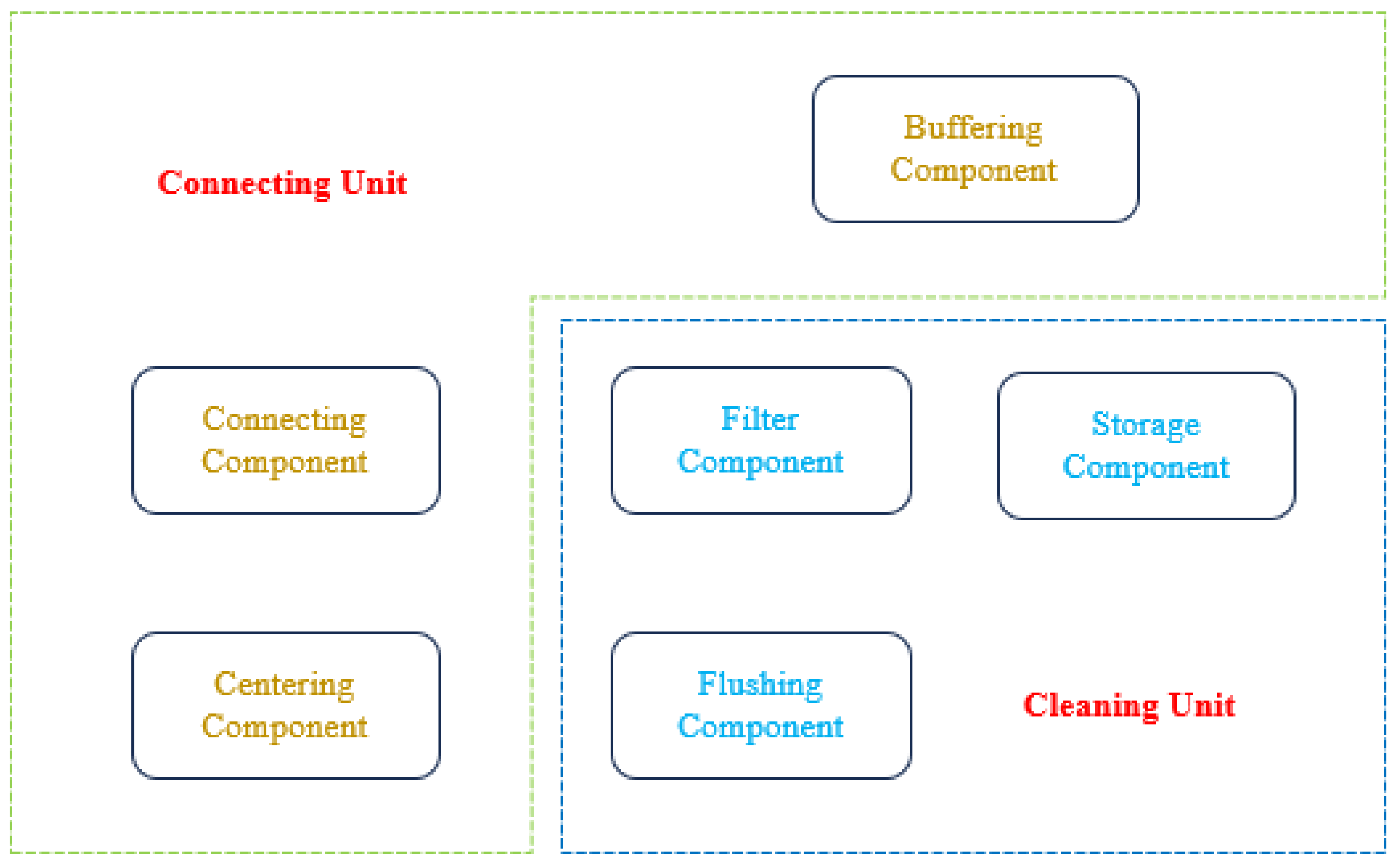
As shown in Figure 2 and Figure 3, the jet wellbore cleaning device consists of a connecting unit and a cleaning unit. When the device is working, the downstroke quick-assembly module is first used to realize the fast connection and position correction between the device and the flushing fluid pipeline. The elastic connection module can effectively absorb the energy generated and reduce the damage to the equipment caused by collisions that may occur when the cleaning device enters the wellbore. After the cleaning device enters the wellbore, the washing fluid drives the hydraulic rotary washing module to continuously rotate and clean the wellbore in an all-around way. After cleaning the wellbore, the flushing fluid flows through the rotary filtration storage module, and the separation of mud and sand from the flushing fluid and the reuse of the flushing fluid are realized by rotary centrifugation.

3. Design of Rotary Jet Wellbore Cleaning Equipment Module

In this chapter, the SolidWorks 2020 software is utilized to design and assemble the required modules. Based on the above system analysis and engineering design, the rotary jet wellbore cleaning equipment adopts a modular architecture and consists of four core functional modules: elastic connection module, downstroke quick-assembly module, hydraulic rotary washing module, and rotary filtration storage module. During the design process, a detailed mechanical structure design was carried out for the specific working environment faced by each module (such as high temperature, high pressure, limited space, complex medium, etc.) and the key functional goals to be achieved. Pressure- and corrosion-resistant steel is suggested for main metal parts and shell materials, such as carbon steel or martensitic alloy steel used for N80 steel pipes; nitrile rubber and neoprene rubber, widely used in LWD, can be selected for non-metal parts. Since the current research goal focuses on the design and innovation of principles and structures, the research team has not yet studied the specific material choices, which will be refined in the next phase of the research work. The core design purpose of the whole set of equipment is to realize a set of wellbore cleaning systems with efficient and rapid disassembly and assembly ability. The equipment is designed to be applied to the normal operation of oil and gas production wells and water injection wells. Under the premise of not interfering with the main working conditions of the wellbore, it can efficiently and reliably complete the cleaning and maintenance operations inside the wellbore, effectively remove fouling and sediments and ensuring the smooth flow of the wellbore and production/injection efficiency.

3.1. Elastic Connection Module

As the key buffer unit of the whole equipment, the core structure of the elastic connection module is shown in Figure 4a, which is mainly composed of four parts: return pipe, spherical headed tube, balloon catheter, and circular pipe cover. The core function of the module is to provide an efficient ‘vibration buffer warehouse’ system for the well washing fluid conveying pipe. Its working principle is as follows: it uses the closed gas storage structure designed inside the module or fills the energy absorption medium, such as high-performance spring, special elastic sponge, etc., to actively absorb and dissipate the strong vibrations, mechanical impacts, and accidental impacts of the equipment during operation in the wellbore. The huge amount of energy generated reduces the external force damage that the equipment may suffer. It is worth noting that the downhole conditions of high temperature and high pressure will affect the temperature and compression resistance and service life of the material and then affect the final impact resistance of the module. Due to the lack of a suitable simulation environment, quantitative analysis of the effect of downhole high-temperature and high-pressure conditions on module function is still planned, which will become the focus of our work in the next stage.
As shown in Figure 4b, the head of the return pipe is locked in the spherical-headed tube by the circular pipe cover, and there is a certain free expansion space in the axial direction, which can achieve shock absorption and buffering by means of cylinders or fillers. The spherical-headed tube is installed in the balloon catheter, and the rubber pad is installed in the annulus part of the spherical-headed tube and balloon catheter, which plays the role of shock absorption and prevents the ball head from falling off the balloon. The diameter of the cleaning pipe is smaller than the diameter of the opening of the spherical headed tube, so the cleaning pipe has limited bending ability, which makes the device easy to pass through the bending section of the wellbore, reduces the friction between the device and the cleaning pipe on the wellbore wall under the condition that it cannot be bent, and reduces the damage to the wellbore wall.

3.2. Downstroke Quick-Assembly Module

This module is mainly composed of the casing, rotating handle, riser pipe, bracket, and transmission gear, as shown in Figure 5a. The main function of this module is to drive the riser pipe and the transmission gear at the same time through the rotating handle. The riser pipe drops and squeezes the connecting plate of the cleaning unit, and the transmission gear drives the bracket to slide and straighten the cleaning unit inward, so as to realize the rapid assembly of the connecting unit and the cleaning unit.
As shown in Figure 5b, the rotating handle is installed in the casing, and the outer side is opened with the gear groove and transmission gear, and the inner protrusion is inserted into the empty groove of the riser pipe wall. The bottom of the riser pipe is embedded within the vertical groove of the side wall of the casing. When pushing the rotating handle, because the bottom of the riser pipe is embedded within the casing, the riser pipe cannot rotate and can only slide upward or downward in the axial direction. At the same time, the rotating handle drives the transmission gear to rotate, so that the bracket slides to the axis, and the lower end of the rotating pipe jointly clamps the liquid inlet pipe of the well washing device and realizes the centering and sealing through the bracket at the front end of the rubber pad. It should be noted that by adjusting the length of the bracket, the module can clamp and connect downhole operation equipment with different standardized specifications, such as a well washing machine, fishing tool, etc., under the condition that the size of the equipment connection end does not exceed the allowable size of the module, to realize the multifunctional utilization ability. Since the standard modelling and data of the downhole equipment have not been collected, a numerical analysis focused on the sealing properties and joint strength has not been completed, and more data support is needed for further design.

3.3. Hydraulic Rotary Washing Module

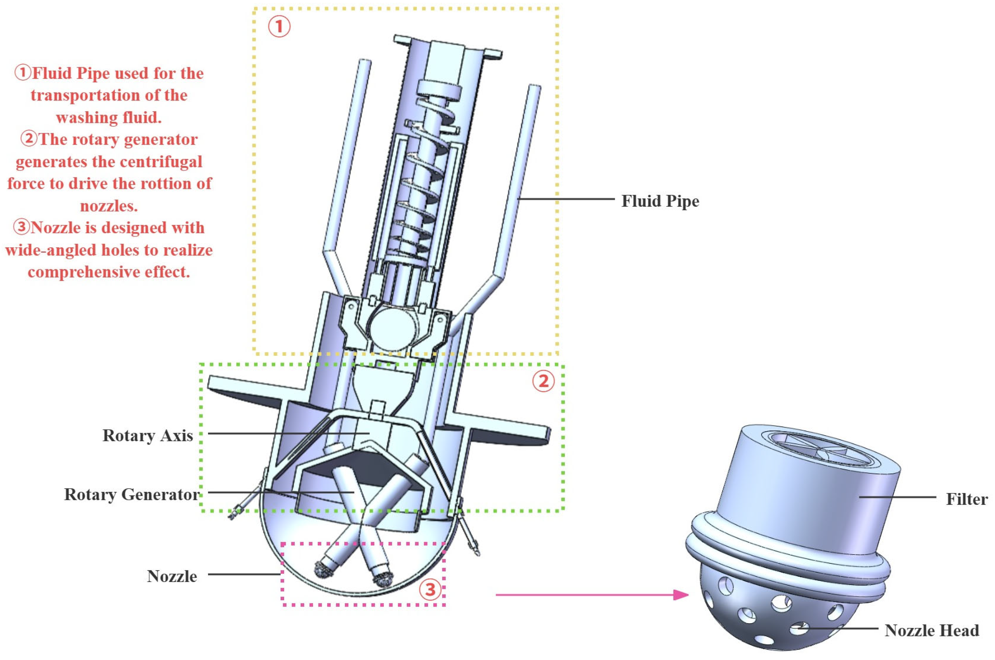
As shown in Figure 6, this module is mainly composed of a fluid pipe, a rotary axis, a rotary generator, and a nozzle. The main function is to use the pressure of the well washing fluid as the power to realize the rotating cleaning of the module, so that the flushing effect of the well washing fluid can completely cover the inner wall of the wellbore and so that the cleaning fluid can effectively penetrate the reservoir outside the flushing wellbore, erode the accumulated mud and sand in the reservoir gap, and restore the production capacity of the reservoir near the wellbore. The traditional radial jet well washer can effectively remove the plugging on the bottom of the oil well, but the cleaning of the well wall depends on the scouring effect of water backflow. At this time, the flow direction of the fluid is parallel to the well wall, and the removal effect of viscous and soft attachments, such as asphaltene and wax deposits, is poor. The nozzle of the module forms an included angle with the well wall, and the well washing fluid can additionally perform a circular cutting motion while washing, thereby improving the actual cleaning effect on the well wall.
When the module is working, the flushing fluid enters the flushing fluid pipe from the return pipe and the wellbore annulus. By adjusting the flow rate of the two nozzles, the rotation direction can be controlled to avoid early failure due to uneven wear of the equipment caused by long-term unidirectional rotation. The nozzle is eccentrically mounted on the rotation generator, and the reaction force generated by the jet emitted from the nozzle provides torque to the rotation generator, so the rotating cleaning function of the cleaning module is realized. Parameters such as nozzle size, eccentricity, damping of module rotation, etc., may be further designed by CFD simulation or field test methods to balance the energy used to drive module rotation and the energy ratio used to clean the wellbore. Our research group is realizing the importance of these parameters and the current lack of research on testing and simulation, which will be a new direction for future research.

3.4. Rotary Filtration Storage Module

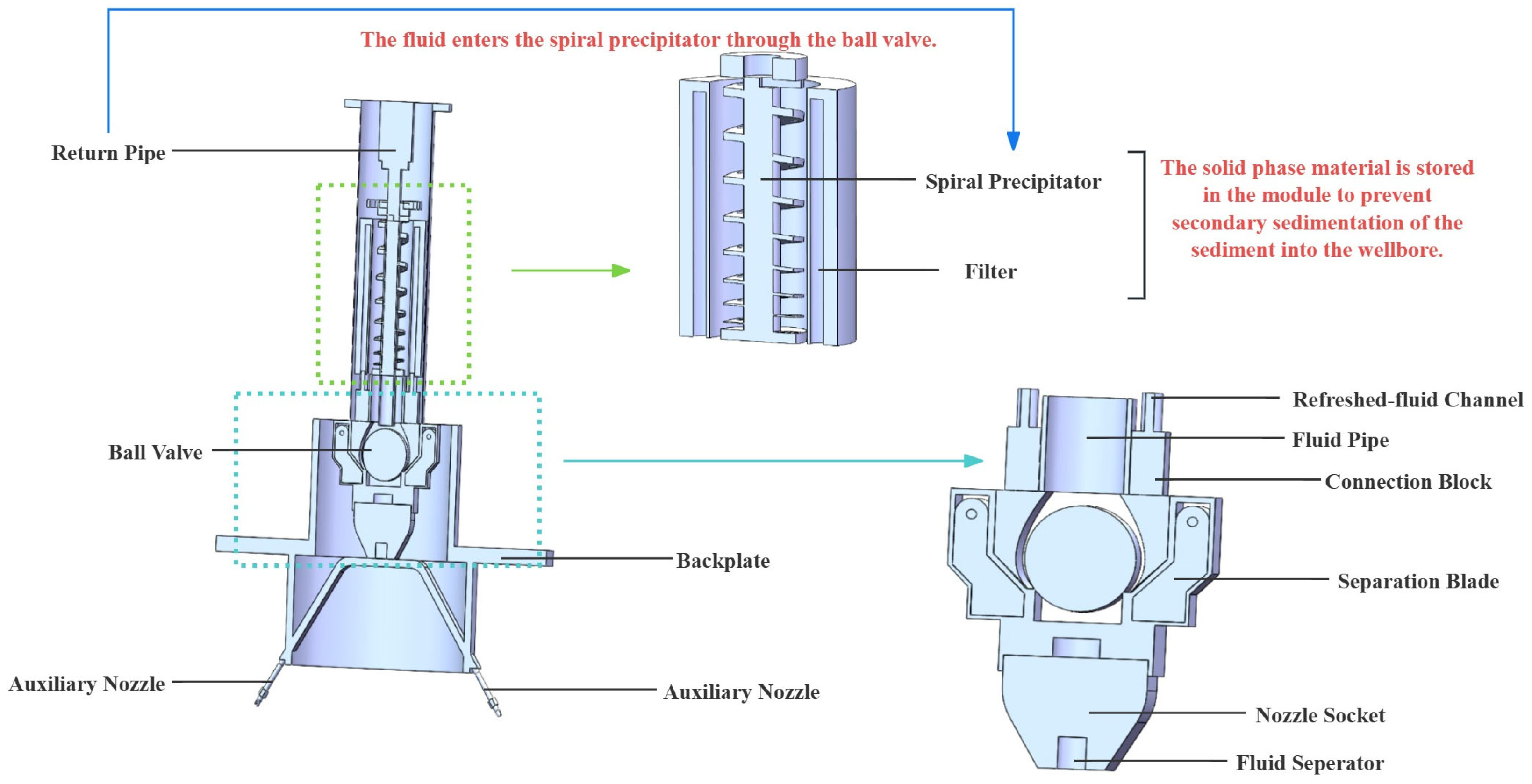
This module is mainly composed of a filter, spiral precipitator, backplate, ball valve, and auxiliary nozzle, as shown in Figure 7. The main function of this module is to collect the backflow formed during the cleaning process, realize the solid–liquid separation of the backflow, store the solid-phase material in the module, and prevent the secondary sedimentation of dense sediments such as mud and sand into the wellbore. At the same time, the washing fluid is sprayed out again through the nozzle after filtration, forming an auxiliary cleaning method, realizing the secondary utilization of the filtrate, and improving energy efficiency. Parameters such as filter pore size, spiral precipitator pitch, and spring constants need to be carefully designed to balance the filtration rate and filtration effect, preventing the filtration rate from being too low to cause the washing fluid to penetrate the formation. However, because the particle size gradation, viscosity, and other parameters of downhole sediment and organic matter have not been analyzed, the quantitative study of relevant parameters is still in the planning stage, and the research team is formulating relevant research plans and putting them into action.
In the cleaning process, the flowback fluid formed by cleaning enters the spiral precipitator through the ball valve and impacts the spiral blade, driving the spiral precipitator to rotate. The filter blocks the solid sediment in the spiral precipitator, and the fluid in the flowback fluid is separated to the other side. Because the ball valve is pushed forward by the flowback fluid, the filtrate cannot enter the flowback channel and instead enters the auxiliary jet channel inside the side and is ejected from the auxiliary nozzle to assist the cleaning module in the cleaning operation.

4. Feasibility Prospects of Rotary Jet Wellbore Cleaning Device

The rotary jet wellbore cleaning device is designed to improve the efficiency of well cleaning in oil and gas wells. The core technology lies in the efficient, rapid-assembly structure design and water-driven cleaning and filtration technology design. The device adopts a modular architecture, which effectively improves the coverage area and effect of wellbore cleaning, realizes the storage of waste and the secondary utilization of the cleaning fluid, and improves energy efficiency. The device consists of two major units: the connection unit and the cleaning unit. The connection unit includes an elastic connection module and a downstroke quick-assembly module. The cleaning unit includes a hydraulic rotary washing module and a rotary filtration storage module. Through reasonable integration and collaboration, each module can give full play to its respective advantages, thereby significantly improving the efficiency and effectiveness of well washing and energy efficiency and providing technical support for the maintenance of complex well conditions.

4.1. Applicability of Rotary Jet Wellbore Cleaning Device

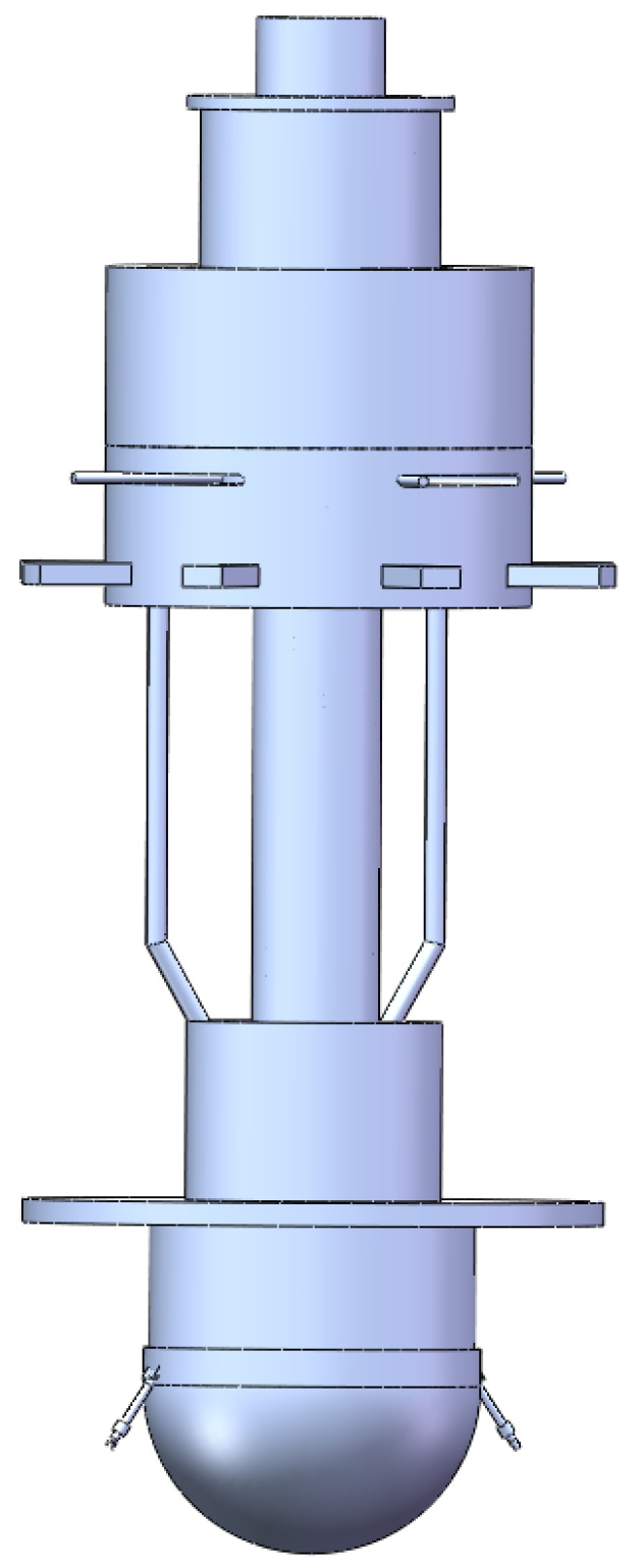
Table 2 summarizes the shortcomings of traditional wellbore cleaning devices. Therefore, the entire device design has taken these aspects into account. The overall assembly design is shown in Figure 8. The equipment adopts a highly modular functional design, which significantly improves the manufacturing efficiency and maintainability of the equipment and provides great convenience for configuration optimization to adapt to different downhole conditions. The connection unit realizes the flexibility and adaptability of the equipment in multiple directions, effectively compensates for the stress caused by the wellbore trajectory deviation or the equipment installation error, and improves the reliability and durability of the equipment under complex trajectories. The rapid disassembly structure greatly simplifies the on-site assembly, replacement, and maintenance process of the tool string and significantly reduces the non-production operation time. The cleaning unit uses the kinetic energy of the fluid to drive the rotary module and the sedimentation storage module, which avoids the energy waste caused by a single scouring, improves the flushing area, and effectively reduces the secondary sedimentation phenomenon, ensuring that the cleaning effect is clean and thorough. These improvements are based on the conceptual design, and the key parameters, such as the cleaning period of the device, the energy efficiency, and the removal rate, could be validated with further field tests. As a conceptual design, the research team has not defined and calculated these specific performance indicators of the equipment, and the next stage of research will focus on the detailed parameters.
As shown in Table 3, the equipment is an innovation focused on the mechanical structure, so the whole device adopts a fully mechanical–hydraulic drive structure design. Electronic equipment will face problems such as cables being too long, intense fluid scouring, and extra equipment volume for installation and sealing under extreme downhole conditions. The adoption and innovation of a fully mechanical structure design can fundamentally avoid the risk of failure and damage of electronic components under extreme downhole conditions (e.g., high temperature, high pressure, high vibration, long immersion in corrosive fluids). Direct monitoring of fluid purity downhole comes at the expense of additional time needed to wait for fluid flowback to be detected, but it significantly improves tool operational reliability and long-term durability in the harsh downhole environment. This highly robust purely mechanical design provides an innovative cleaning solution that is efficient, reliable, economical, and especially suitable for harsh downhole environments for wellbore maintenance operations in oil and gas fields. It not only greatly reduces the risk of job interruption and maintenance costs caused by equipment failure but also more effectively solves the reliability bottlenecks and survivability challenges faced by traditional well washing tools that rely on complex electronic sensors or control systems under extreme conditions, ensuring the success rate and sustainability of cleaning operations.

4.2. Optimization Prospect of Rotary Jet Wellbore Cleaning Device

The rotary jet wellbore cleaning equipment proposed here greatly improves the efficiency and flexibility of the well washing maintenance process by using an elastic connection module and downstroke quick-assembly module. In a follow-up study, the structural reinforcement of the moving parts can be carried out by collecting on-site installation and maintenance data so as to further optimize the force structure, reduce the wear of moving parts, and improve the overall strength.
The rotary filtration storage module uses the kinetic energy of the flowback fluid to realize rotary centrifugation and filtration and reuses the flowback fluid, which effectively improves the energy efficiency and the utilization rate of the well washing fluid and improves the overall cleaning effect. By using computational fluid dynamics and other simulation processes, the spiral structure can be further optimized to achieve a more efficient and reliable storage filtering function.
The water-driven rotary sandblasting nozzle structure realizes high-speed spin under the direct drive of high-pressure water flow and overcomes the problem of cleaning the blind area of fixed nozzles. Follow-up work can improve the design of the jet nozzle, improve the utilization rate of jet energy, and reduce the erosion and corrosion of the jet to the nozzle and other positions.

5. Conclusions and Prospects

In this study, a rotary jet wellbore cleaning device was designed for the technical requirements of efficient wellbore cleaning, and its workflow and core structure were optimized. A stable and reliable mechanical structure is formed by integrating the innovative design of the downstroke quick-assembly module and hydraulic rotary washing module. The following conclusions are drawn:
(1)
The elastic connection module solves the problems of wellbore damage and equipment working difficulties caused by the rigid connection of traditional equipment and improves the adaptability of cleaning equipment to different types of wellbores. The downstroke quick assembly module realizes the rapid connection and straightening of the equipment through a single-step operation, reduces the labor consumption of the traditional equipment in the assembly and disassembly process, shortens the non-working time, and improves the overall work efficiency. Since the team is currently working on a conceptual design, quantitative analysis of the structural size requires further study to meet the installation requirements for typical usage scenarios.
(2)
Compared with the traditional axial jet cleaning equipment, the hydraulic rotary washing module greatly improves the jet coverage area, improves the cleaning effect, effectively restores the permeability of the wellbore and reservoir, and prolongs the working life of the wellbore. The rotary filtration storage module filters and stores impurities, reduces the probability of equipment being washed and worn by impurities, and realizes the recovery and reuse of the well washing fluid, realizes multi-angle and multi-level rotary cleaning, and significantly improves the cleaning coverage and operation intensity. Field tests and simulations lack performance parameters and influencing factors, and the research team has planned to further screen influencing factors and conduct quantitative calculations and analysis in a study next year to examine the improvements in the cleaning effect, energy efficiency, and removal efficiency.
(3)
The whole equipment design considers the shortages of traditional washing equipment. The flexible structure design effectively avoids sticking accidents caused by insufficient rigidity under complex working conditions and significantly improves operational safety. The introduction of a compression modular design in the connection part not only simplifies the disassembly process but also more reliably prevents failure caused by loosening or fatigue of the connection parts. Cleaning efficiency and uniformity of coverage are greatly improved by the rotating jet, and residue removal is achieved. The spiral sedimentation storage module can effectively separate and temporarily store the waste generated by cleaning and prevent the occurrence of backflow and secondary deposition, thus ensuring continuous and efficient cleaning performance and reducing the efficiency loss caused by interrupted cleaning.
(4)
The rotary jet wellbore cleaning equipment effectively improves the coverage area of cleaning and scouring by using fluid kinetic energy efficiently and improves the cleaning efficiency and effect. The integrated cleaning fluid filtration and secondary utilization module conceptually improves the utilization rate of the cleaning fluid by the equipment, reduces the overall energy consumption and raw material loss of the equipment, and realizes the joint optimization of the cleaning degree, efficiency, energy, and material consumption of the well washing operation. Quantitative data should be analyzed in further works.

Author Contributions

Conceptualization, S.L. and Q.F.; methodology, S.L. and Z.J.; software, Z.J. and S.L.; validation, S.Y. and X.S.; formal analysis, Q.F.; resources, Z.J. and S.Y.; writing—original draft preparation, S.L. and Q.F.; writing—review and editing, X.S. and S.Y. All authors have read and agreed to the published version of the manuscript.

Funding

This research received no external funding.

Data Availability Statement

The raw data supporting the conclusions of this article will be made available by the authors on request.

Conflicts of Interest

The authors declare no conflicts of interest.

Terms and Abbreviations

LWDLogging While Drilling
CFDComputational Fluid Dynamics
Wellbore cleaningAn engineering operation that injects well washing fluid into wellbore through pumping equipment to remove impurities to improve wellbore working conditions
Water injectionA technical means of injecting qualified water into an oil reservoir through an injection well, with the aim of supplementing formation energy and maintaining reservoir pressure
Downhole falling objectsAll kinds of objects accidentally dropped into the well during oil and gas drilling or downhole operation, including but not limited to drilling tools, tools, instruments, parts, etc.
Jet cleaningWellbore cleaning with a high-pressure fluid jet, mainly achieved by two mechanisms, namely shock pressure wave and bottom hole crossflow
Tools jammingCommon accidents in drilling operations, usually caused by tools stuck in keyways, debris accumulation, or downhole falling objects, etc.

References

  1. Wang, H.; Liu, C.; Yao, F.; Song, X.; Xu, X.; Liu, Y.; Zhao, L.; Wang, P.; Ma, B. Research and application of cleaning and automation technology for downhole operations in Daqing Oilfield. Pet. Sci. Technol. Forum 2022, 41, 86–93. [Google Scholar] [CrossRef]
  2. Yu, J. Technical research and application of oilfield cleaning operation. Energy Conserv. Pet. Petrochem. Ind. 2023, 13, 56–60. [Google Scholar] [CrossRef]
  3. Sun, J.; Yang, J.; Bai, Y.; Lyu, K.; Liu, F. Research progress and development of deep and ultra-deep drilling fluid technology. Pet. Explor. Dev. Online 2024, 51, 1022–1034. [Google Scholar] [CrossRef]
  4. Da, W.; Wei, Z.; Jun, J. The key problems of ultra-deep drilling engineering. Chin. Sci. Bull. 2018, 63, 2698–2706. [Google Scholar] [CrossRef]
  5. Hahn, S.; Polat, B.; Jamali, S.; Wittig, V.; Bracke, R. Water jet drilling technology for application in geothermal environments. Geomech. Tunn. 2022, 15, 74–81. [Google Scholar] [CrossRef]
  6. Wang, H.; Huang, H.; Bi, W.; Ji, G.; Zhou, B.; Zhuo, L. Deep and ultra-deep oil and gas well drilling technologies: Progress and prospect. Nat. Gas Ind. B 2022, 9, 141–157. [Google Scholar] [CrossRef]
  7. Zhao, J.; Ren, L.; Lin, C.; Lin, R.; Hu, D.; Wu, J.; Song, Y.; Shen, C.; Tang, D.; Jiang, H. A review of deep and ultra-deep shale gas fracturing in China: Status and directions. Renew. Sustain. Energy Rev. 2025, 209, 115111. [Google Scholar] [CrossRef]
  8. Amer, M.; Salem, S.; Farahat, M.; Salem, A. Reducing drilling cost of geothermal wells by optimizing drilling operations: Cost effective study. Untradtional Resour. 2025, 7, 100196. [Google Scholar] [CrossRef]
  9. Brice, L.; Jean, D. Simultaneous initiation and growth of multiple radial hydraulic fractures from a horizontal wellbore. J. Mech. Phys. Solids 2015, 82, 235–258. [Google Scholar] [CrossRef]
  10. Wu, X.; Lai, X.; Hu, J.; Lu, C.; Yang, X.; Zhou, Y.; Wu, M. Efficiency-safety coordination optimization in drilling process under complex formations. Neurocomputing 2025, 630, 129732. [Google Scholar] [CrossRef]
  11. Zhang, H.; Yang, S.; Liu, D.; Li, Y.; Luo, W.; Li, J. Wellbore cleaning technologies for shale-gas horizontal wells: Difficulties and countermeasures. Nat. Gas Ind. B 2020, 7, 190–195. [Google Scholar] [CrossRef]
  12. Li, Y.; He, M.; Cai, M.; Xu, S. Hole Cleaning and Critical Transport Rate in Ultra-Deep, Oversized Wellbores. Fluid Dyn. Mater. Process. 2025, 21, 799–817. [Google Scholar] [CrossRef]
  13. Hu, W.; Zhang, J.; Guan, N.; Zhu, H. Cuttings transport characteristics and multi-objective optimization design of a novel hole cleaning tool. Geoenergy Sci. Eng. 2025, 254, 2949–8910. [Google Scholar] [CrossRef]
  14. Gao, W. Casing Drilling Technology to Drilling Site. Appl. Mech. Mater. 2012, 2016, 63–66. [Google Scholar] [CrossRef]
  15. Chen, M.; Si, L.; Dai, J.; Liu, Y.; Wang, Z.; Wei, D.; Li, X. A variable structure robust control strategy for automatic drilling tools loading and unloading system. Control Eng. Pract. 2025, 161, 106340. [Google Scholar] [CrossRef]
  16. Huang, H.; Li, J.; Sun, X.; Yu, B.; Zhang, W.; Ma, L. Influence analysis on the storage capacity of hydrogen-blended natural gas pipeline. Comput. Energy Sci. 2024, 1, 3–16. [Google Scholar] [CrossRef]
  17. Shao, X.; Cui, B.; Liu, Y.; Xie, X.; Song, G.; Reng, L.; Xu, J. Application of circular well washing technology in South Yanchuan coalbed gas field. Reserv. Eval. Dev. 2022, 12, 651–656. [Google Scholar] [CrossRef]
  18. Ji, Y. Discussion on low density well washing technology and its application in oil wells. Chem. Eng. Equip. 2020, 7, 147–148. [Google Scholar] [CrossRef]
  19. Ai, X.; Chen, M. Wellbore Cleaning Degree and Hydraulic Extension in Shale Oil Horizontal Wells. Fluid Dyn. Mater. Process. 2024, 20, 661–670. [Google Scholar] [CrossRef]
  20. Al-Shargabi, M.; Davoodi, S.; Wood, D.; Al-Rubaii, M.; Minaev, M.; Rukavishnikov, V.S. Hole-cleaning performance in non-vertical wellbores: A review of influences, models, drilling fluid types, and real-time applications. Geoenergy Sci. Eng. 2024, 233, 212551. [Google Scholar] [CrossRef]
  21. Xian, B.; Liu, G.; Bi, Y.; Gao, D.; Wang, L.; Cao, Y.; Shi, B.; Zhang, Z.; Zhang, Z.; Tian, L.; et al. Coalbed methane recovery enhanced by screen pipe completion and jet flow washing of horizontal well double tubular strings. J. Nat. Gas Sci. Eng. 2022, 99, 104430. [Google Scholar] [CrossRef]
  22. Gao, D. Some research advances in well engineering technology for untradtional hydrocarbon. Nat. Gas Ind. B 2022, 9, 41–50. [Google Scholar] [CrossRef]
  23. Sun, X.; Tao, L.; Qu, J.; Yao, D.; Hu, Q. Evaluating the effectiveness of cleaning tools for enhanced efficiency in reamed wellbore operations. Geoenergy Sci. Eng. 2025, 246, 213620. [Google Scholar] [CrossRef]
  24. Sun, X.; Hu, Q.; Yan, L.; Chen, Y.; Zhang, K.; Qu, J. A magnetic torque optimization method for a hydraulic-magnetic coupling-drive cuttings cleaning tool. Nat. Gas Ind. B 2019, 6, 374–383. [Google Scholar] [CrossRef]
  25. Youssef, A.S.; Mahmoud, A.A.; Elkatatny, S.; Al Shafloot, T. A review of the critical conditions required for effective hole cleaning while horizontal drilling. Petroleum 2025, 11, 143–157. [Google Scholar] [CrossRef]
  26. Yang, L.; Li, Y.; Wang, D.; Guo, Y.; Li, D. Research on deposition particles carrying with washing tools during well cleaning. J. Pet. Sci. Eng. 2022, 219, 111097. [Google Scholar] [CrossRef]
  27. Wu, D.; Zhang, H.; Zhang, S.; Tan, J.; Sun, P.; Luo, Y.; Gao, S.; Xue, Y. Determining whether the swirling jet is applicable in bottom-hole cleaning: A CFD study. J. Pet. Sci. Eng. 2022, 208, 109317. [Google Scholar] [CrossRef]
  28. Song, X.; Li, G.; Huang, Z.; Wang, H.; Tian, S.; Shi, H. Experimental study on horizontal wellbore cleanout by rotating jets. J. Pet. Sci. Eng. 2010, 75, 71–76. [Google Scholar] [CrossRef]
  29. Pandya, S.; Ahmed, R.; Shah, S. Experimental study on wellbore cleanout in horizontal wells. J. Pet. Sci. Eng. 2019, 177, 466–478. [Google Scholar] [CrossRef]
  30. Song, H.; Guo, J.; Li, J.; Zhang, S.; de Oliveira, A.J.S.; He, A. Application of multifunctional wellbore cleaning fluid in the removal of residual drilling fluids in ultra-deep wells: Research progress and prospects. Geoenergy Sci. Eng. 2024, 243, 213329. [Google Scholar] [CrossRef]
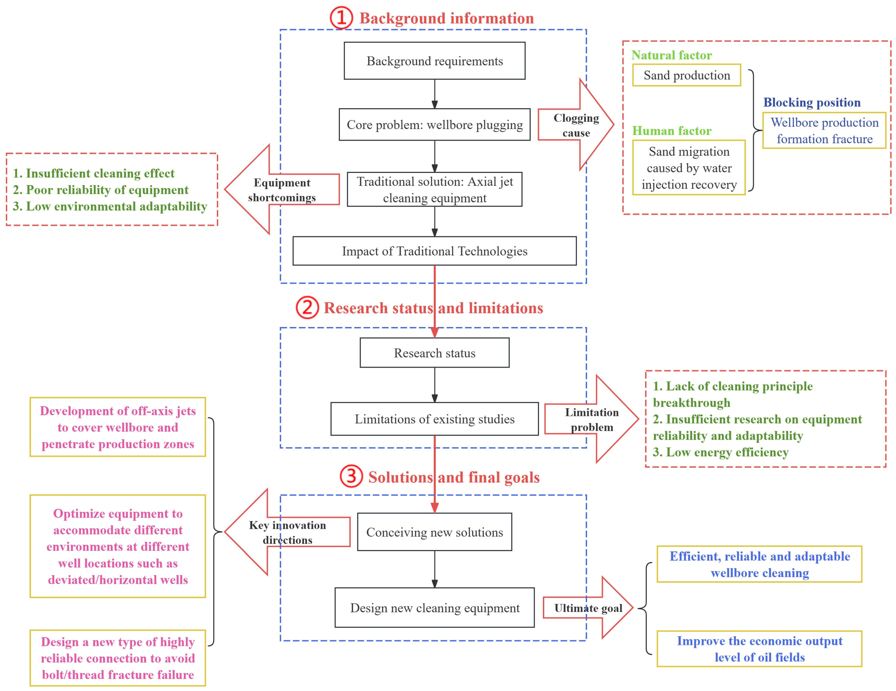
Figure 1. Steps and points covered in this review.
Processes 13 03015 g001
Figure 2. The module diagram of the rotary jet wellbore cleaning device.
Processes 13 03015 g002
Figure 3. The procedure diagram of the rotary jet wellbore cleaning device.
Processes 13 03015 g003
Figure 4. Elastic connection module: (a) overall appearance diagram, (b) half-sectional diagram.
Processes 13 03015 g004
Figure 5. Downstroke quick-assembly module: (a) overall appearance diagram, (b) half-sectional diagram.
Processes 13 03015 g005
Figure 6. Hydraulic rotary washing module.
Processes 13 03015 g006
Figure 7. Rotary filtration storage module.
Processes 13 03015 g007
Figure 8. Overall assembly design.
Processes 13 03015 g008
Table 1. Relevant patents in recent years.
PatentsKey InnovationsYearCountry
Downhole tool for wellbore cleaning or for moving fluids in a wellboreDriving unit powered by a conductive device2012CN
Jet hole cleaning toolPressure-regulated rotating jet2019CN
Method for cleaning horizontal wellbore during drillingMechanical scraper promotes the removal of mud and sand and prevents accumulation2024RU
Method and apparatus for automatic drill removalSelf-cleaning integrated cuttings capture and throttling system2024US
Use of high-power ultrasound for improved hole cleaning in drilling operationsHigh-frequency power ultrasonic generators and sensors2025SA
Table 2. Deficiencies of traditional wellbore cleaning devices.
TypePhenomenaImpact
Tool and string damage [22,23]Improper connection or jamming of mechanical scraping tools causes damage to the inner wall of the tubing and casingRisk of casing damage and corrosion
Low efficiency [24,25,26]Complicated installation and disassembly process, highly dependent on manual operation and calibration, and high auxiliary timeAdditional labor costs and downtime of equipment
Limited cleaning effect [27,28,29]Mainly relies on directional jet, limited cleaning coverage, and a blind areaInadequate removal effect and remaining deposits
Improper treatment of flowback fluid [30]Low utilization rate of well cleaning fluid, insufficient performance of fluid, and extensive treatment of waste liquidReduced cleaning efficiency, increased waste liquid treatment cost, and additional environmental protection pressure
Table 3. Risks and improvements of the washing devices.
ModuleRisk LevelRiskAnalysisImprovements
Connection ModuleHighEquipment jammingTraditional equipment areas lack the ability to adjust the curvatureBalloon catheter design adaptable for different angles of wellbore trajectory
Assembly ModuleLowLow efficiencyComplicated manual operation and complex connection processFast connection and sealing of equipment with a single rotation
HighDownhole objects caused by connection failureFailure to connect parts such as screws or threadsRiser pipe and bracket arrays avoid joint failures caused by rotational and vibration conditions
Washing ModuleLow–MediumRepeated flushing and low energy efficiencyFixed direction of flow cannot cover the wellbore and bottom hole directionMulti-angle, large-area coverage through rotating nozzles
Storage ModuleLow–MediumSediment reverse flow deposition reduces the cleaning effectIneffective collection and storage of washed sedimentUsing a spiral precipitator to collect sediment to prevent backflow
LowExcessive dosage of washing fluidMost well cleaning fluids are used for recyclingReturned fluid is purified and reused
Disclaimer/Publisher’s Note: The statements, opinions and data contained in all publications are solely those of the individual author(s) and contributor(s) and not of MDPI and/or the editor(s). MDPI and/or the editor(s) disclaim responsibility for any injury to people or property resulting from any ideas, methods, instructions or products referred to in the content.