Article

Experimental Study on Water-Hammer-Effect Fracturing Based on High-Frequency Pressure Monitoring

1
Shale Gas E&D Project Department, CNPC Chuanqing Drilling Engineering Co., Ltd., Chengdu 610052, China
2
State Key Laboratory of Petroleum Resources and Engineering, China University of Petroleum (Beijing), Beijing 102249, China
*
Author to whom correspondence should be addressed.
Processes 2025, 13(9), 2900; https://doi.org/10.3390/pr13092900
Submission received: 19 August 2025 / Revised: 8 September 2025 / Accepted: 9 September 2025 / Published: 11 September 2025
(This article belongs to the Section Energy Systems)

Abstract

Horizontal well multi-stage fracturing is the primary technology for deep shale gas development, but dense multi-cluster fractures are prone to non-uniform initiation and propagation, requiring real-time monitoring and interpretation techniques to adjust fracturing parameters. Although high-frequency water hammer pressure-monitoring technology shows diagnostic potential, the correlation mechanism between pressure response characteristics and multi-cluster fracture morphology remains unclear. This study utilized outcrop rock samples from the Longmaxi Formation shale to construct a long-injection-tube pipeline system and a 1 kHz high-frequency pressure acquisition system. Through a true triaxial fracturing simulation test system, it systematically investigated the effects of flow rate (50–180 mL/min) and fracturing fluid viscosity (3–15 mPa·s) on water hammer signal characteristics and fracture morphology. The results reveal that when the flow rate rose from 50 mL/min to 180 mL/min, the initiation efficiency of transverse fractures significantly improved, artificial fractures more easily broke through bedding plane limitations, and fracture height propagation became more complete. When the fracturing fluid viscosity increased from 3–5 mPa·s to 12–15 mPa·s, fracture height propagation and initiation efficiency significantly improved, but fewer bedding plane fractures were activated. The geometric complexity of fractures positively correlated with the water hammer decay rate. This research demonstrates a link between water hammer signal features and downhole fracture morphology, giving a theoretical basis for field fracturing diagnostics.

1. Introduction

China has abundant unconventional oil and gas reserves, which have become a key force in the country’s oil and gas production [1,2]. Multi-stage multi-cluster fracturing in horizontal wells is one of the critical technologies for economically and efficiently developing unconventional reservoirs [3,4,5]. Fracture localization is an important necessity in hydraulic fracturing diagnostics [6]. Fracturing diagnostic technology utilizing a water hammer pressure wave was introduced in 2016. This approach is recognized for its affordability, straightforward implementation, and excellent real-time monitoring capabilities. Pump shutdown water hammer pressure waves can be used for inverse analysis of fracture locations, which in turn aids in fracturing process selection and optimization of operational parameters [7,8]. In industrial applications, particularly in the oil and gas extraction sector, water hammer pressure-monitoring technology has achieved significant results. For example, in the Haynesville shale gas field, Panjaitan et al. successfully combined water hammer analysis, step-down tests, and micro seismic data to identify the diversion effects in multi-cluster horizontal wells [9]. Field applications have shown that this technology can detect fracture initiation points with an accuracy rate exceeding 85%, enable real-time optimization of fracturing parameters, and increase well productivity by 15–20% [9].
The principal mechanism of fracturing diagnostics using water hammer pressure waves is as follows: When the hydraulic fracturing pumping stage is completed, the plunger pump of the fracturing truck stops, resulting in a sudden shift in fluid velocity at the wellhead. This quick shift creates pressure pulses in the wellbore, known as water hammer pressure waves, which transmit up and down multiple times between the wellhead and the operating formation until they are attenuated and disappear owing to friction along the wellbore and dissipation in the region of fracture [10]. The characteristics of water hammer pressure waves depend on wellbore structure, wellbore geometry, properties of fluids in the well, and geometric configuration of hydraulic fractures [11,12,13]. Therefore, studying the response characteristics and variation patterns of pump shutdown water hammer pressure waves is significant for evaluating actual fracture morphology downhole and assisting in fracturing operation decision-making.
To date, many studies have been conducted on water hammer pressure-monitoring technologies. In laboratory experiments, research has primarily focused on the propagation of water hammer waves in pipeline systems after valve closure excitation. In long-distance pipelines, sudden valve closure can cause enormous pressure changes. Zhang et al. demonstrated through experimental research that a reasonable valve closure protocol can ensure the safety of long-distance pipelines [14]. Pipeline leakage also shows distinct indications in pressure drop characteristics and valve-closure water hammer waveforms, allowing calculation of leak location and volume through pressure attenuation characteristics [15,16]. Valve-closure pressure fluctuations in pipelines can also be used to study pressure wave propagation velocity. Hu et al. constructed a 160 m long horizontal pipeline test system to study four different methods for calculating water hammer wave velocity [17]. Some scholars have investigated the effects of different factors on water hammer morphology. Qiu et al. established a laboratory setup of a wellbore–perforation–fracture system to study the impact of pump shutdown time, pipe friction, and local resistance parameters on wellhead water hammer response patterns [18]. Iriarte et al. conducted a detailed analysis of 29 wells with specific water hammer characteristics [19]. By comparing water hammer pressure wave periods, amplitudes, duration, and decay rates, combined with chemical tracer results and production data, they studied the influence of completion types, formation parameters, and stimulation measures on water hammer response characteristics. Qiu et al. proposed a novel fracturing diagnosis method based on water hammer reflection characteristics and conducted numerical simulations to investigate the influence of wellbore cementing and diameter change on water hammer reflection properties [20].
In numerical simulation, domestic and international scholars have constructed pump shutdown water hammer responses in wellbores based on pressure transient models. By establishing connections between fracture dimensions using hydro-electric analogies, the downhole stimulated fracture scale can be evaluated [21,22,23,24]. Some scholars have also processed water hammer pressure signals through cepstral analysis methods, which can accurately identify reflection wave characteristics and convert reflection time to depth information to determine fracture information through precise velocity models [25,26,27,28]. Yong et al. suggested a technique that utilized high-frequency water hammer pressure-monitoring technology for assessing the efficacy of diversion in shale gas wells [29]. This method effectively assesses fracture initiation locations within stages, diversion effectiveness, and mechanical isolation of bridge plugs by high-frequency acquisition and analysis of water hammer pressure waves generated during operations. Qiu et al. proposed a multi-dimensional analysis method that, combined with transient flow modeling and FLUENT verification, systematically studied the effects of fracture existence, location, and length on water hammer response characteristics [30]. Based on mass balance principles and considering both perforation friction and fluid leak-off effects, Sun et al. established wellbore fracture boundary conditions to develop a novel water hammer modeling approach [31].
Current laboratory experimental systems predominantly employ long pipeline configurations, with limited studies focusing on the propagation characteristics of pump-shutdown water hammer pressure waves in wellbore–fracture systems during hydraulic fracturing. Moreover, laboratory experiments cannot precisely replicate the actual formation environment during fracturing processes. Conventional pressure-monitoring devices typically operate at sampling frequencies of 1–10 Hz, which are insufficient to capture millisecond-scale pressure variations following pump shutdown, resulting in poor analytical precision of water hammer pressure wave signals. Additionally, existing numerical models fail to adequately simulate the complexity of actual wellbore and fracture systems, leading to significant errors in water hammer signal analysis. To address these limitations, this study conducts hydraulic fracturing simulation experiments based on high-frequency, high-precision monitoring of water hammer effects. Utilizing a true triaxial integrated fracturing simulation system, we perform water-hammer-effect simulation experiments with horizontal well multi-cluster perforation on typical cubic samples from real shale outcrops. The study investigates the influence of various parameter combinations, including flow rate and fracturing fluid viscosity, on multi-cluster fracture initiation, propagation patterns, and water hammer waveform characteristics. The research findings provide valuable reference and practical significance for the development of water hammer wave-based fracture interpretation methods in unconventional shale reservoirs.

2. Methods

2.1. Fracturing Sample Preparation

The tests’ natural shale was taken from the Sichuan Basin’s Longmaxi Formation shale outcrop. With a 50.6% quartz concentration, a 33.4% clay content, and comparatively low amounts of carbonate and pyrite (9.8% and 6.2%, respectively), the mineral composition of shale mostly comprises siliceous and clay minerals. Bedding planes and natural fractures containing pyrite and carbonate minerals are typically seen in rock samples (Figure 1). The results of the rock sample mechanical parameter tests are shown in Table 1. The pre-fracturing characteristics of the rock samples are shown in Table 2.
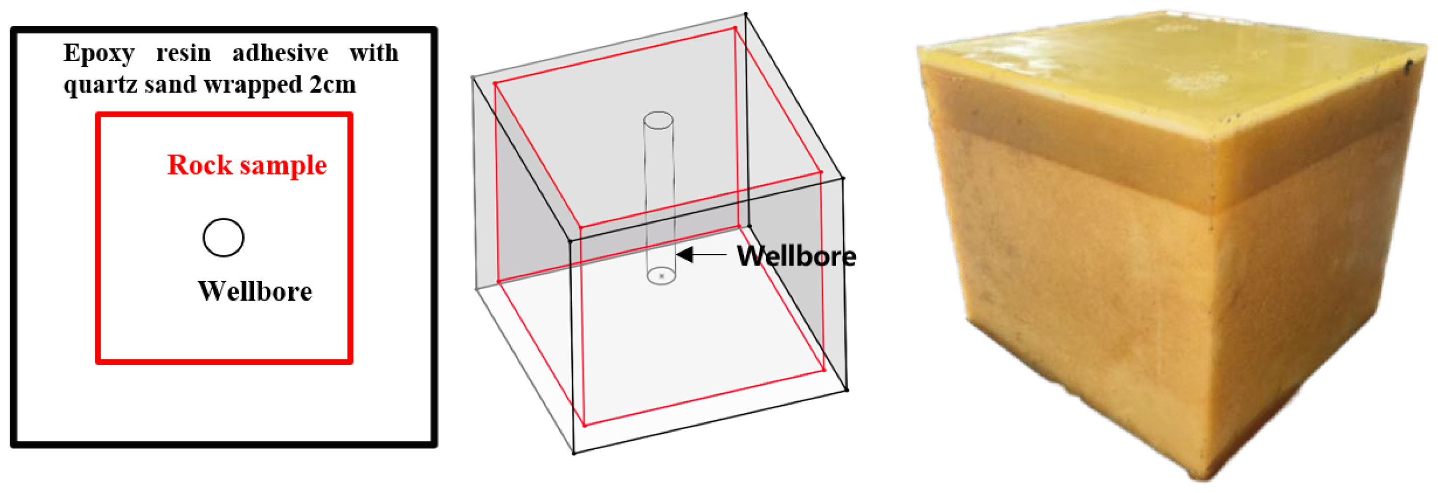
A total of six cubic rock specimens were prepared for this experiment to investigate the effects of varying flow rates and fracturing fluid viscosity on water hammer characteristics and fracture morphology. Cubic rock samples of 30 cm × 30 cm × 30 cm were created by cutting large chunks of shale outcrop in parallel and perpendicular orientations to bedding planes. To prevent rapid filtration of fracturing fluid from the sample surface during the experiment, the rock sample surface was coated with a mixture of epoxy resin adhesive and quartz sand over a 2 cm thickness (Figure 2), achieving complete sealing of the sample.
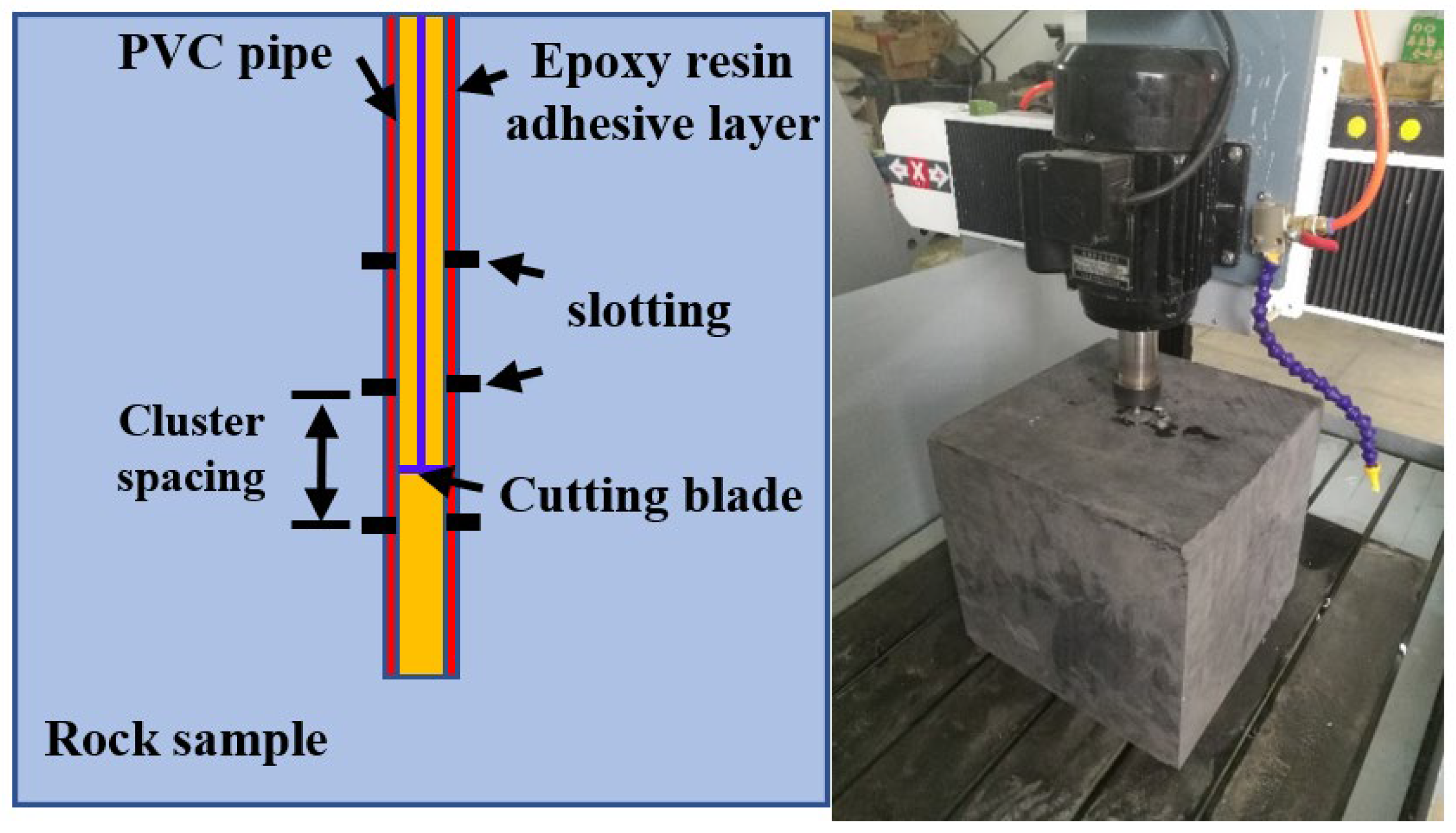
Drill a hole with a diameter of 28 mm and a length of 27 cm at the center of the rock sample surface along the direction parallel to the bedding planes. Use a PVC pipe with an outer diameter of 23.5 mm and an inner diameter of 22.5 mm to simulate the wellbore. First, fix the bottom of the wellbore with epoxy resin adhesive, followed by the area between the PVC pipe’s outer wall and the rock sample (Figure 3). Finally, use a slotting equipment to make annular slots inside the wellbore that penetrate the rock sample by 2–3 mm, simulating several clusters of holes inside the section.

2.2. Experimental Parameter Design

Based on the actual in situ stress conditions in the Longmaxi Shale reservoir, the experimental vertical stress was set to 20 MPa, the highest horizontal principal stress to 24 MPa, and the lowest horizontal principal stress to 10 MPa.
Using similarity criteria [32,33,34,35], the experimental principal injection parameters were determined, as Equations (1) and (2) demonstrate. The fracture propagation characteristic radius was 15~25 m, the fracturing fluid viscosity was 2~3 mPa·s, and the field flow rates were 10, 14, and 18 m3/min. Approximately 100, 140, and 180 mL/min were the computed experimental flow rates since the experimental fracture propagation characteristic radius was roughly 0.15 m.
μ 1 = α μ f t m a x , 1 t m a x , f Q f Q 1 3 / 2 E f E 1 13 / 2 K 1 K f 9 2 / 5
t m a x = R m a x 5 2 K Q E
where E is the plane strain elastic modulus; P a ;   K is the modified fracture toughness, P a m 1 / 2 ;   Q is the pump injection rate, m 3 / s ; R m a x is the characteristic fracture propagation radius, m ;   t m a x is the characteristic fracture propagation time, s ;   μ is the viscosity of fracturing fluid, mPa·s; α is the similarity coefficient; and subscripts l and f represents laboratory parameters and field parameters, respectively.
According to the geometric similarity principle [36,37], the cluster spacing at the site is 5–15 m, which can be calculated using Equation (3) to obtain an experimental cluster spacing of approximately 2–6 cm.
S 1 S f = β L 1 L f
where L is the fracture half-length, m ;   S is the cluster spacing, m ;   a n d   β is the similarity coefficient.

2.3. Experimental Equipment

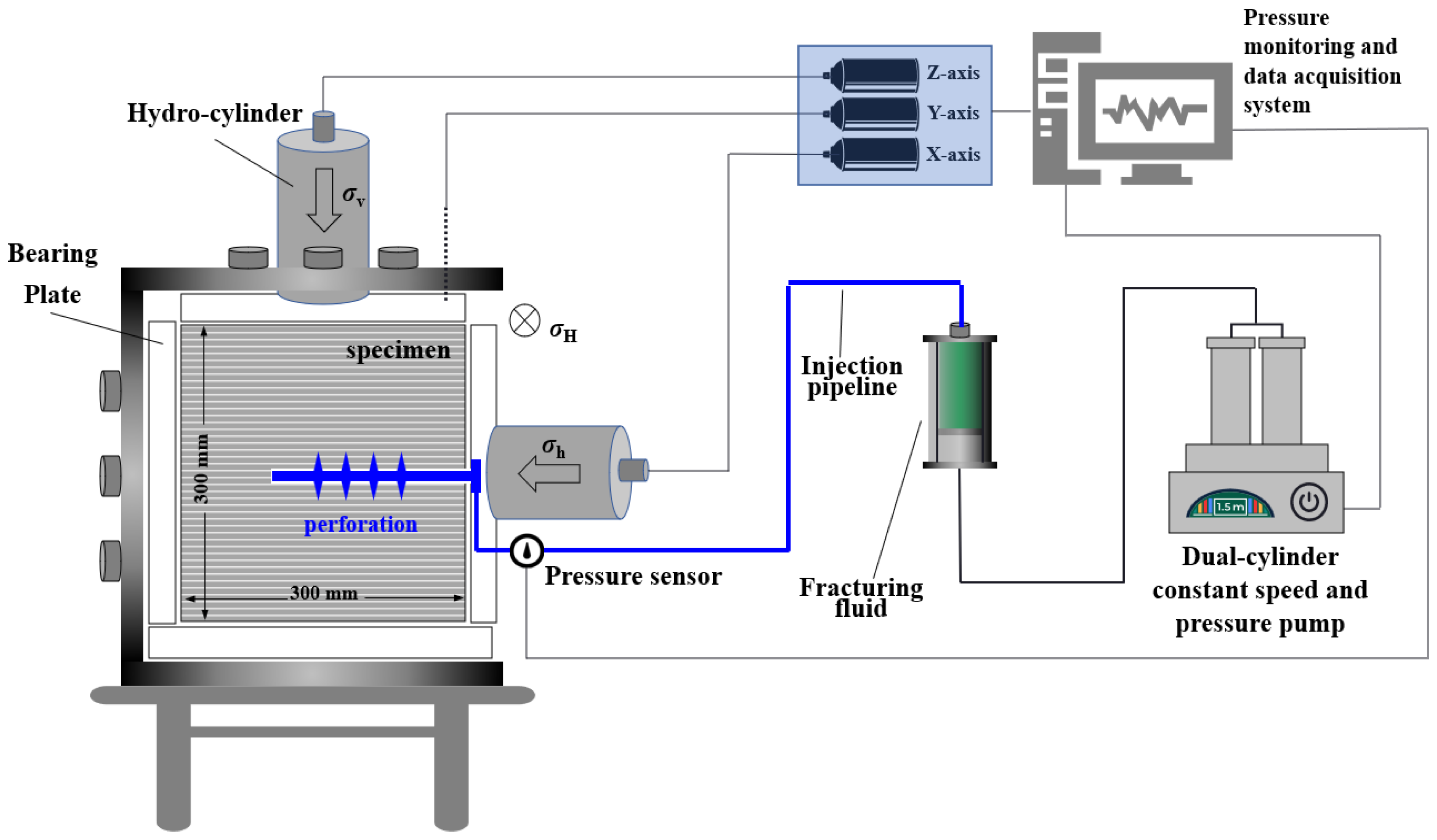
A true triaxial hydraulic fracturing simulation system (Figure 4) was used in the experiment. This system is a proprietary testing apparatus comprising a core chamber, a hydraulic loading system, a dual-cylinder constant-speed constant-pressure pump, a Hastelloy intermediate vessel, a temperature control system, a pressure sensor, a data acquisition system, and auxiliary accessories. Based on this system, the injection pipeline length was improved by replacing the original injection pipeline with a 75 m high-pressure oil pipeline to simulate the real formation environment and generate clear water hammer signals. The pressure sensor used in the test has a frequency response of 1 kHz. The output of the pressure sensor is a standard 4–20 mA current signal, and its built-in driver software can directly display and record the acquired signals. To ensure the accuracy of measurement data, all sensors underwent rigorous calibration prior to the experiment. The calibration process involved using a known standard pressure source to compare sensor readings against standard pressure values, ensuring measurement errors were controlled within ±0.5%.

2.4. Experimental Procedures and Methodology

Experimental procedure: (1) Push the sample into the rock chamber, apply triaxial stress through the hydraulic loading system, and maintain stable triaxial stress. (2) Activate the injection system first to fill the 75 m high-pressure tubing with fracturing fluid, then initiate the data acquisition system. When the pressure suddenly drops, indicating rock fracture, instantly stop the pump within 5 s. The specific experimental scheme is shown in Table 3.

3. Results and Discussion

3.1. Influence of Flow Rate

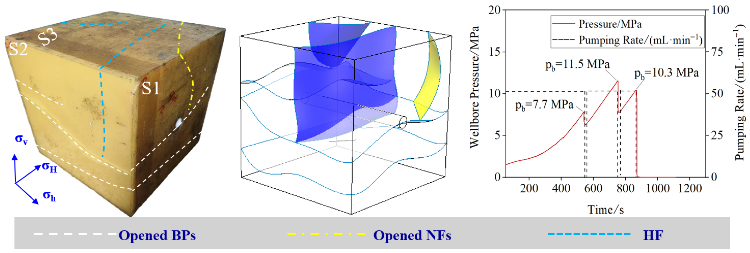
For specimen #1 under a flow rate of 50 mL/min, the fracture morphology, three-dimensional reconstruction, and pressure curve are shown in Figure 5. This specimen developed three bedding fractures, one natural fracture, and one hydraulic fracture. The hydraulic fracture initiated from the second perforation cluster extended vertically upward to the sample boundary and downward until reaching a bedding plane, where it stopped further propagation. The vertical communication height was approximately 10 cm. Pressure curve analysis shows that the first fracture pressure of 7.7 MPa was recorded at 541 s, with a pre-fracture pressure rise rate of 0.025 MPa/s. After fracturing, the pressure decreased by approximately 1 MPa, then rapidly increased to 11.5 MPa at 749 s, reaching the maximum fracture pressure. This may have been caused by the hydraulic fracture initiated from the second cluster connecting with the lower bedding plane. The second pressure rise rate was 0.023 MPa/s, significantly higher than the first pre-fracture rise rate. The third fracture pressure was 10.3 MPa, with the pre-fracture pressure rise rate further increasing to 0.025 MPa/s. The pump was stopped at 868 s.
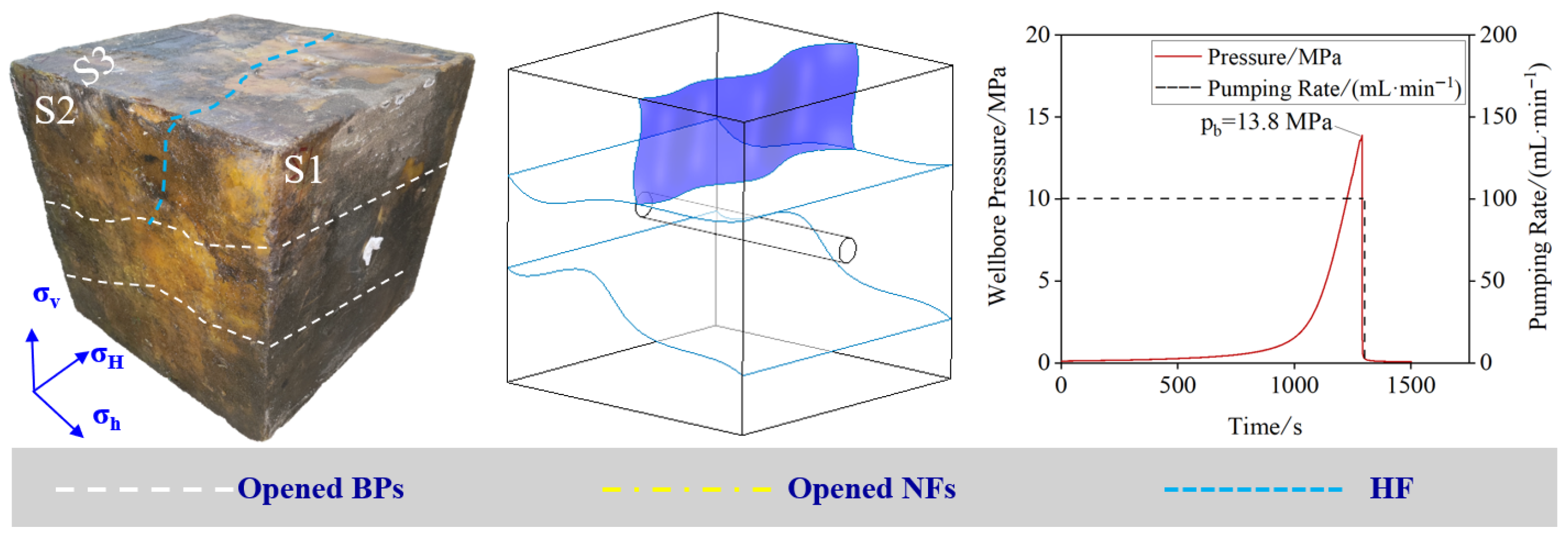
For specimen #2 under a flow rate of 100 mL/min, the fracture morphology, three-dimensional reconstruction, and pressure curve are shown in Figure 6. This specimen had one hydraulic fracture and two bedding fractures. The aperture of the first bedding plane in the lower part of the sample was greater. When the hydraulic fracture from the third cluster extended downward to the first bedding plane, the fracturing fluid quickly leaked off along the bedding plane, preventing the hydraulic fracture from breaking through the bedding plane and instead extending along the path of least resistance (the bedding plane) to the sample boundary. The final vertical communication height was approximately 12 cm. Pressure curve analysis indicates that the fracture pressure of 13.8 MPa was recorded at 1291 s, with a pre-fracture pressure rise rate of 0.053 MPa/s. The pump was stopped at 1300 s.
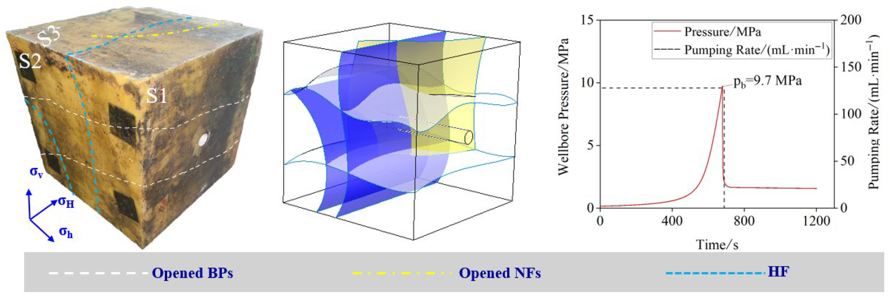
For specimen #3 under a flow rate of 140 mL/min, the fracture morphology, three-dimensional reconstruction, and pressure curve are shown in Figure 7. This specimen developed two bedding fractures, one natural fracture, and two hydraulic fractures. The hydraulic fractures initiated from the fourth and fifth clusters extended vertically downward through two bedding planes below and connected with one natural fracture. Pressure curve analysis shows that the fracture pressure of 9.7 MPa was recorded at 679 s, with a pre-fracture pressure rise rate of 0.06 MPa/s. The pump was stopped at 681 s.
For specimen #4 under a flow rate of 180 mL/min, the fracture morphology, three-dimensional reconstruction, and pressure curve are shown in Figure 8. This specimen developed two bedding fractures and three hydraulic fractures. Compared to specimens #1, #2, and #3, specimen #4 activated significantly more bedding planes with better vertical communication, indicating that higher flow rates reduce the restriction of bedding planes on fracture height and significantly improve the initiation efficiency of transverse hydraulic fractures. The hydraulic fractures initiated from clusters 1, 2, and 6 extended vertically downward. The hydraulic cracks directly entered and extended through the bedding planes when they came into contact with smaller-aperture, well-cemented bedding planes below. The extension path deflected several times along the bedding planes owing to the lubricating effect of the fracturing fluid and weak cementation characteristics. Eventually, the hydraulic fractures extended to the sample boundary, where the fracturing fluid quickly leaked off the sample’s bottom. Pressure curve analysis indicates that the fracture pressure of 7.4 MPa was recorded at 307 s, with a pre-fracture pressure rise rate of 0.064 MPa/s. The pump was stopped at 308 s.
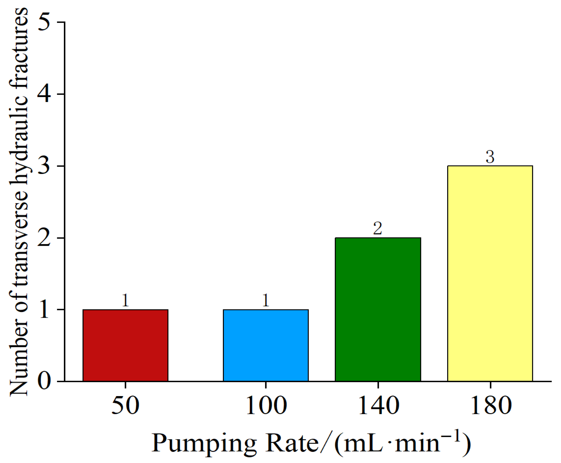
The experimental findings reveal that as the flow rate steadily increases, the initiation efficiency of transverse hydraulic fractures was significantly improved, increasing from 1 transverse hydraulic fracture under 50 mL/min to three transverse hydraulic fractures under 180 mL/min (Figure 9). Furthermore, under high flow rate conditions, artificial fractures tend to break through bedding limitations, resulting in more complete fracture height extension.

3.2. Influence of Fracturing Fluid Viscosity

For specimen #5 with a viscosity of 8–10 mPa·s, the fracture morphology and pressure curve are shown in Figure 10. This specimen developed three bedding fractures and three hydraulic fractures, all of which were transverse hydraulic fractures. The hydraulic fractures initiated from the first and third clusters extended to connect with bedding planes above and below the wellbore, terminating at the lowermost bedding plane. The hydraulic fracture initiated from the second cluster penetrated through the lowermost bedding plane and extended to the sample boundary. The vertical extension distance of the fracture was 15 cm. Pressure curve analysis shows that the fracture pressure of 7.4 MPa was recorded at 723 s, with a pre-fracture pressure rise rate of 0.027 MPa/s. The pump was stopped at 725 s.
For specimen #6 with a viscosity of 12–15 mPa·s, the fracture morphology and pressure curve are shown in Figure 11. This specimen developed one bedding fracture and four hydraulic fractures, including three transverse hydraulic fractures and one longitudinal fracture. The first, second, and third clusters of rock samples show cracks extending vertically downward, gradually deviating away from the wellbore. The entire hydraulic fracture surface is severely distorted, with the three initially separate hydraulic fractures gradually converging. These three hydraulic fractures extend upward through the bedding plane above the wellbore to the fracture surface, with a vertical extension distance of approximately 28 cm. Pressure curve analysis indicates that the fracture pressure of 7.4 MPa was recorded at 744 s, with a pre-fracture pressure rise rate of 0.036 MPa/s. The pump was stopped at 748 s.
In this study, fracturing fluid viscosity plays a crucial role in controlling fracture vertical expansion. When the viscosity increased from 3–5 mPa·s to 12–15 mPa·s, the vertical extension of the fractures increased from 10 cm to 28 cm. Under high viscosity conditions, the number of transverse fractures increased from one to four. However, due to the low filtration properties of high-viscosity fracturing fluids, the number of bedding fractures opened decreased from three to one. Similar studies have also explored the role of fracturing fluid viscosity in different rock types. For example, Ishida et al. studied the influence of fluid viscosity on the hydraulic fracturing mechanism and found that higher viscosity fluids enhance fracture extension and stability in hard rocks, while limiting fluid loss in softer rocks [38]. Additionally, Shimizu et al., through discrete element analysis, studied the influence of fluid viscosity and particle size distribution on hydraulic fracturing in hard rocks, finding that high-viscosity fluids infiltrate fractures more slowly, but contribute to the formation of longer fractures, thereby improving vertical fracture extension [39].

3.3. Relationship Between Water Hammer Curves and Fracture Morphology

To reveal the relationship between high-frequency pressure response characteristics during fracture propagation and multi-cluster fracture extension patterns, water hammer signals monitored during the fracturing process were analyzed. This study uses the decay rate calculation approach proposed by Luo et al. [22] to quantify the attenuation properties of water hammer waves. This method first extracts the peak points from each cycle of the water hammer wave signal, recording their pressure values P i (i = 1,2,…,n) and corresponding times T i , followed by normalization processing. The calculation formulas are shown in Equations (4) and (5).
T i = T i T 1
P i = P i P stop / P 1 P stop
where P 1 is the cycle’s greatest peak pressure point, and T 1 is the time at which P 1 occurs. The curve fitting of formula 6 represents the decay of the water hammer signal. Formulas 1 and 2 have been used to normalize the analytical values of Formula 6 in this formula. The water hammer’s rate of decay may be represented by the value of B, whereas the value of A is about 1. The water hammer and attenuation curves for specimens #1, #3, #5, and #6 are displayed in Figure 12. The decay rates of rock samples are shown in Table 4. The experimental data were fitted using exponential decay analysis, yielding R2 ≥ 0.85 for all samples (Table 3), which validates the effectiveness of the proposed model.
P i = A × e T i B
For specimen #1, after pump shutdown at 546.3 s, pressure dropped sharply, then quickly rose to 6.44 MPa, and after approximately 0.3 s, attenuated to a stable value of 6.41 MPa, with a pressure drop of about 0.03 MPa. The amplitude attenuation showed an exponential decrease, with the first few peaks declining more rapidly, then gradually becoming smoother, and finally stabilizing at a relatively constant pressure level. The time interval between adjacent peaks of the water hammer wave was approximately 0.02–0.03 s. As time progressed, the spacing between peaks slightly increased and the oscillation frequency decreased, which might be related to the damping effect of the pipeline system and fluid viscous losses.
For specimen #3, after pump shutdown at 681.2 s, the pressure similarly dropped sharply, then quickly rose to 4.0 MPa, and after 0.3 s finally stabilized at 3.25 MPa, with a total pressure drop of 0.75 MPa, representing a relative attenuation magnitude of approximately 18.75%. The amplitude attenuation exhibited two stages: an initial stage (681.2–681.35 s) with more intense attenuation, where the pressure rapidly decreased from its peak value in a short time, followed by a later stage (after 681.35 s) with more gradual attenuation, gradually approaching a stable value. The time interval between main peaks was approximately 0.05–0.08 s. As time progressed, the oscillation period slightly lengthened, the oscillation amplitude gradually decreased, and the waveform became smoother. Initially, 2–3 distinct main peaks appeared, after which the oscillation intensity significantly decreased, basically stabilizing within about 0.3 s.
For specimen #5, the initial peak pressure of the water hammer wave was 1.4 MPa, finally stabilizing at 1.03 MPa, with a total pressure drop of 0.37 MPa, representing a relative attenuation magnitude of approximately 26.4%. Between 725.4 and 725.6 s, there was a sharp pressure fluctuation, including a process of first decreasing then increasing. In the middle stage (725.6–725.8 s), the amplitude attenuated rapidly, with pressure quickly decreasing from its peak value. In the later stage (after 725.8 s), the decay rate slowed down, gradually approaching stability. The entire attenuation process lasted about 0.6 s. The time interval between the main peaks was approximately 0.1–0.15 s. The oscillation showed non-uniform characteristics, with initial peaks being more concentrated and with dramatic amplitude changes, followed by gradually lengthening oscillation periods and continuously decreasing amplitudes. After about 3–4 main oscillation cycles, the pressure wave stabilized.
For specimen #6, the initial peak pressure was 1.82 MPa, finally stabilizing at 1.54 MPa, with a total pressure drop of 0.28 MPa, representing a relative attenuation magnitude of approximately 15.4%. The amplitude attenuation exhibited a typical exponential decay pattern, with a faster decay rate in the early stage (748.6–748.8 s) where pressure dropped sharply within about 0.2 s, followed by more gradual attenuation after 748.8 s, gradually approaching a stable value with a smaller gradient.
The water hammer curves of the four specimens showed an overall oscillatory attenuation trend, with higher initial pump shutdown pressure levels and amplitudes, followed by gradual pressure attenuation and decreased oscillation amplitude due to the combined effects of wellbore–perforation friction resistance, fracture opening and closing, and filtration effects. However, compared to specimens #3, #5, and #6, specimen #1 had the smallest decay rate of the water hammer curve (Table 4). From the three-dimensional reconstruction of the specimens, it can be seen that specimen #1 had a simple fracture geometric morphology (Figure 13) and fewer transverse fractures, resulting in low fluid flow resistance and a relatively simple propagation path for the water hammer wave, allowing the water hammer curve to quickly reach equilibrium. In contrast, specimens #3, #5, and #6 had more complex fracture morphologies and more transverse fractures, which increased the fracture volume and enlarged the filtration area within the fractures, gradually releasing wellbore pressure to the formation and leading to higher decay rates of the water hammer curves.

4. Conclusions

(1) At lower flow rates (50–100 mL/min), fracturing fluid primarily flowed and leaked off into natural fractures and bedding planes, with only one transverse fracture initiated. Fracture height expansion was significantly limited by bedding planes, with a vertical communication height of only 10–12 cm. When the flow rate increased to 140–180 mL/min, the number of hydraulic transverse fractures increased to 2–3, which could effectively penetrate through bedding planes, resulting in more complete fracture height expansion and approximately 40% improvement in vertical stimulation capability.
(2) Fracturing fluid viscosity is a key factor controlling the vertical expansion capability of fractures. When viscosity increased from 3–5 mPa·s to 12–15 mPa·s, the vertical expansion distance of fractures increased from 10 cm to 28 cm, and the number of transverse fractures increased from one to four under high-viscosity conditions. However, due to the low filtration characteristics of high-viscosity fracturing fluid, the number of opened bedding fractures decreased from three to one.
(3) The water hammer curves of the four specimens showed an overall oscillatory attenuation trend, with higher initial pump shutdown pressure levels and amplitudes, followed by gradual pressure attenuation and decreased oscillation amplitude due to the combined effects of wellbore–perforation friction resistance, fracture opening and closing, and filtration effects. Based on regression analysis and statistical significance testing, this study found that fracture complexity significantly influences the water hammer decay rate. An increase in the number of fractures is positively correlated with the water hammer decay rate, and this relationship is statistically significant (correlation coefficient = 0.89, p-value < 0.05). This may be because simpler fracture geometric morphology results in lower fluid flow resistance and a more singular water hammer wave propagation path, allowing the water hammer curve to quickly reach equilibrium, leading to a smaller decay rate. When the fracture geometric morphology is complex, the increased fracture volume enlarges the filtration area within fractures, gradually releasing wellbore pressure to the formation, resulting in a higher decay rate of the water hammer curve.

Author Contributions

Conceptualization, Y.L.; investigation, Y.L., H.S. and L.Z.; methodology, Y.L. and H.S.; writing—original draft, Y.L., L.Y., H.J. and R.S.; formal analysis, L.Z., L.Y., H.J., Z.Z. and Y.Z.; writing—review and editing, Z.Z. and Y.Z.; software, R.S. All authors have read and agreed to the published version of the manuscript.

Funding

This research received no external funding.

Data Availability Statement

The original contributions presented in this study are included in the article material. Further inquiries can be directed to the corresponding author.

Conflicts of Interest

Authors Yanchao Li, Hu Sun, Longqing Zou, Liang Yang, Hao Jiang, Zhiming Zhao were employed by the company CNPC Chuanqing Drilling Engineering Co., Ltd. The remaining authors declare that the research was conducted in the absence of any commercial or financial relationships that could be construed as a potential conflict of interest.

References

  1. Zou, C.N.; Yang, Z.; Cui, J.W.; Zhu, R.K.; Hou, L.H.; Tao, S.Z.; Yuan, X.J.; Wu, S.T.; Lin, S.H.; Wang, L.; et al. Formation mechanism, geological characteristics, and development strategy of nonmarine shale oil in China. Pet. Explor. Dev. 2013, 40, 15–27. [Google Scholar] [CrossRef]
  2. Zhao, W.Z.; Hu, S.Y.; Hou, L.H.; Yang, T.; Li, X.; Guo, B.C.; Yang, Z. Types and resource potential of continental shale oil in China and its boundary with tight oil. Pet. Explor. Dev. 2020, 47, 1–11. [Google Scholar] [CrossRef]
  3. Li, G.X.; Wang, F.; Pi, X.J.; Liu, H. Optimized application of geology-engineering integration data of unconventional oil and gas reservoirs. China Pet. Explor. 2019, 24, 147–152. [Google Scholar] [CrossRef]
  4. Jiao, F.Z. Re-recognition of “unconventional” in unconventional oil and gas. Pet. Explor. Dev. 2019, 46, 847–855. [Google Scholar] [CrossRef]
  5. Lei, Q.; Xu, Y.; Cai, B.; Guan, B.; Wang, X.; Bi, G.; Li, H.; Li, S.; Ding, B.; Fu, H.; et al. Progress and prospects of horizontal well fracturing technology for shale oil and gas reservoirs. Pet. Explor. Dev. 2022, 49, 191–199. [Google Scholar] [CrossRef]
  6. Carey, M.A.; Mondal, S.; Sharma, M.M. Analysis of water hammer signatures for fracture diagnostics. In Proceedings of the SPE Annual Technical Conference and Exhibition, Houston, TX, USA, 28–30 September 2015; SPE: Richardson, TX, USA, 2015. No. SPE-174866-MS. [Google Scholar] [CrossRef]
  7. Carey, M.A.; Mondal, S.; Sharma, M.M.; Hebert, D.B. Correlating water hammer signatures with production log and microseismic data in fractured horizontal wells. In Proceedings of the SPE Hydraulic Fracturing Technology Conference, The Woodlands, TX, USA, 9–11 February 2016; SPE: Richardson, TX, USA, 2016. No. SPE-179108-MS. [Google Scholar] [CrossRef]
  8. Hwang, J.; Szabian, M.J.; Sharma, M.M. Hydraulic fracture diagnostics and stress interference analysis by water hammer signatures in multi-stage pumping data. In Proceedings of the Unconventional Resources Technology Conference (URTeC), Austin, TX, USA, 24–26 July 2017; URTEC: Austin, TX, USA, 2017. No. URTEC-2687423-MS. [Google Scholar] [CrossRef]
  9. Panjaitan, M.L.; Moriyama, A.; McMillan, D.; Dunaeva, A.; Rutledge, L.; Xu, J.; Parkhonyuk, S.; Kabannik, A.; Korkin, R.; Warren, M. Qualifying diversion in multi clusters horizontal well hydraulic fracturing in haynesville shale using water hammer analysis, step-down test and microseismic data. In Proceedings of the SPE Hydraulic Fracturing Technology Conference and Exhibition, The Woodlands, TX, USA, 23–25 January 2018; SPE: Richardson, TX, USA, 2018. No. SPE-189850-MS. [Google Scholar] [CrossRef]
  10. Dung, N.; David, C.; Tom, D.; Jon, S.; Nico, R.; Annie, O. Practical applications of water hammer analysis from hydraulic fracturing treatments. In Proceedings of the SPE Hydraulic Fracturing Technology Conference and Exhibition, The Woodlands, TX, USA, 4–6 May 2021; SPE: Richardson, TX, USA, 2021. No. SPE-204154-MS. [Google Scholar] [CrossRef]
  11. Ma, X.; Zhou, F.; Andrade, J.A.O.; Gosavi, S.V.; Burch, D. Evaluation of water hammer analysis as diagnostic tool for hydraulic fracturing. In Proceedings of the Unconventional Resources Technology Conference (URTeC), Denver, CO, USA, 22–24 July 2019; URTEC: Denver, CO, USA, 2019. No. URTEC-2019-935-MS. [Google Scholar] [CrossRef]
  12. Bergant, A.; Tijsseling, A.S.; Vítkovský, J.P.; Covas, D.I.C.; Simpson, A.R.; Lambert, M.F. Parameters affecting water-hammer wave attenuation, shape and timing—Part 2: Case studies. J. Hydraul. Res. 2008, 46, 382–391. [Google Scholar] [CrossRef]
  13. Saldungaray, P.; Duenckel, R.; Palisch, T. Reducing hydraulic fracturing HSE footprint through the application of a non-radioactive method for proppant placement and propped fracture height assessment. In Proceedings of the SPE Middle East Health, Safety, Security, and Environment Conference and Exhibition, Doha, Qatar, 22–24 September 2014; SPE: Richardson, TX, USA, 2014; p. SPE-170333-MS. [Google Scholar] [CrossRef]
  14. Zhang, J.Q.; Xu, Y.; Zhang, J.J.; Su, J.F. Apply relief valve against surge to protect long-distance pipeline. Oil Gas Storage Transp. 2006, 25, 58–61. [Google Scholar] [CrossRef]
  15. Zhao, B.L.; Xu, S.R.; Yu, T.C.; Shao, Y. Variation of transient pressure in leaking water pipe network. China Water Wastewater 2019, 35, 40–45. [Google Scholar] [CrossRef]
  16. Guo, X.L.; Yang, K.L.; Guo, Y.X.; Wang, T.; Fu, H. Transient pressure rise method for leak detection in pipeline systems. J. Basic Sci. Eng. 2011, 19, 20–28. [Google Scholar] [CrossRef]
  17. Hu, X.D.; Li, Z.L.; Zhou, F.J.; Qiu, Y.; Li, Y.J.; Luo, Y.H. Water hammer waveform-based experimental study on wave velocity inversion method. Water Resour. Hydropower Eng. 2022, 53, 106–118. [Google Scholar] [CrossRef]
  18. Qiu, Y.; Hu, X.D.; Zhou, F.J.; Jiang, Z.S.; Wang, Y.J.; Lu, X.T.; Li, J.Y.; Yi, P.K. Study on influence factors of wellhead water hammer response characteristics after fracturing pumps shutdown. Chin. J. Hydrodyn. 2023, 38, 965–973. [Google Scholar] [CrossRef]
  19. Iriarte, J.; Merritt, J.; Kreyche, B. Using water hammer characteristics as a fracture treatment diagnostic. In Proceedings of the SPE Oklahoma City Oil and Gas Symposium, Oklahoma City, OK, USA, 27–31 March 2017; SPE: Richardson, TX, USA, 2017. No. SPE-185087-MS. [Google Scholar] [CrossRef]
  20. Qiu, Y.; Hu, X.; Zhou, F.; Yi, P.; Wang, Y.; Jiang, Z. A New Investigation of Wellbore Parameters Influence on Shut-In Pressure Transient Signatures from Water Hammer Fracture Diagnostics. In Proceedings of the SPE International Hydraulic Fracturing Technology Conference and Exhibition, Muscat, Oman, 12–14 September 2023. [Google Scholar]
  21. Mondal, S. Pressure Transients in Wellbores: Water Hammer Effects and Implications for Fracture Diagnostics. Master’s Thesis, The University of Texas at Austin, Austin, TX, USA, 2010. [Google Scholar]
  22. Haustveit, K.; Dahlgren, K.; Greenwood, H.; Peryam, T.; Kennedy, B.; Dawson, M. New age fracture mapping diagnostic tools-A STACK case study. In Proceedings of the SPE Hydraulic Fracturing Technology Conference and Exhibition, The Woodlands, TX, USA, 24–26 January 2017; SPE: Richardson, TX, USA, 2017. No. SPE-184862-MS. [Google Scholar] [CrossRef]
  23. Luo, Y.H.; Hu, X.D.; Zhou, F.J.; Qiu, Y.; Lu, X.T.; Li, J.Y.; Wang, Y.J. A new water hammer decay model: Analyzing the interference of multiple fractures and perforations on decay rate. SPE J. 2023, 28, 1973–1985. [Google Scholar] [CrossRef]
  24. Shen, J.G.; He, H.Y.; Li, Y.C.; Zou, L.Q.; Wang, Y.X.; Zhu, Z.Y.; Guo, L.K.; Fu, S.R. An investigation of data analysis method for hydraulic fracturing based on the water hammer effect. Unconv. Resour. 2023, 3, 284–290. [Google Scholar] [CrossRef]
  25. Parkhonyuk, S.; Fedorov, A.; Kabannik, A.; Korkin, R.; Nikolaev, M.; Tsygulev, I. Measurements while fracturing: Nonintrusive method of hydraulic fracturing monitoring. In Proceedings of the SPE Hydraulic Fracturing Technology Conference and Exhibition, The Woodlands, TX, USA, 23–25 January 2018; SPE: Richardson, TX, USA, 2018. No. SPE-189866-MS. [Google Scholar] [CrossRef]
  26. Wang, X.Q.; Dong, Y.; Li, P.C.; Jin, J.; Lu, D.T. Location estimation of subsurface fluid-filled fractures: Cepstral predominant peak analysis and numerical study. Phys. Fluids 2022, 34, 043102. [Google Scholar] [CrossRef]
  27. Wang, X.Q.; Zhao, L.; Wang, Z.Y.; Xiu, C.H.; Jia, G.L.; Dong, Y.; Lu, D.T. Data analysis method of pump shutdown pressure based on water hammer effect and cepstrum transformation. Reserv. Eval. Dev. 2023, 13, 108–116. [Google Scholar] [CrossRef]
  28. Korkin, R.; Parkhonyuk, S.; Fedorov, A.; Badazhkov, D.; Kabannik, A. High frequency pressure monitoring and data analytics for stimulation efficiency determination: New perspectives or potential limits. In Proceedings of the SPE Hydraulic Fracturing Technology Conference and Exhibition, The Woodlands, TX, USA, 4–6 February 2020; SPE: Richardson, TX, USA, 2020. No. SPE-199762-MS. [Google Scholar] [CrossRef]
  29. Yong, R.; Qiu, Y.; Zhou, F.J.; Hu, X.D.; Song, Y.; Zhou, X.J. The evaluation of temporary plugging effect in shale gas wells based on high-frequency water hammer pressure. Pet. Sci. Bull. 2024, 9, 789–797. [Google Scholar] [CrossRef]
  30. Qiu, Y.; Hu, X.D.; Zhou, F.J.; Li, Z.L.; Li, Y.J.; Luo, Y.H. Water hammer response characteristics of wellbore-fracture system: Multi-dimensional analysis in time, frequency and quefrency domain. J. Pet. Sci. Eng. 2022, 213, 110425. [Google Scholar] [CrossRef]
  31. Sun, S.; He, Y.; Li, Y.; Liu, L.; Liu, Y.; Zou, L.; Ma, H. A Novel Comprehensive Water Hammer Pressure Model for Fracture Geometry Evaluation. SPE J. 2025, 30, 5350–5366. [Google Scholar] [CrossRef]
  32. Detournay, E. Mechanics of hydraulic fractures. Annu. Rev. Fluid Mech. 2016, 48, 311–339. [Google Scholar] [CrossRef]
  33. Dontsov, E.V. An approximate solution for a penny-shaped hydraulic fracture that accounts for fracture toughness, fluid viscosity and leak-off. Roy. Soc. Open Sci. 2016, 3, 160737. [Google Scholar] [CrossRef] [PubMed]
  34. Madyarov, A.; Prioul, R.; Zutshi, A.; Seprodi, N.; Groves, D.; Pei, J.; Wong, S. Understanding the impact of completion designs on multi-stage fracturing via block test experiments. In Proceedings of the 55th US Rock Mechanics/Geomechanics Symposium, Houston, TX, USA, 18–25 June 2021; ARMA: Alexandria, VA, USA, 2021. No. ARMA-2021-1309. [Google Scholar]
  35. Bunger, A.P.; Jeffrey, R.G.; Detournay, E. Application of scaling laws to laboratory-scale hydraulic fractures. In Proceedings of the 40th US Symposium on Rock Mechanics (USRMS), Anchorage, AK, USA, 25–29 June 2005; ARMA: Alexandria, VA, USA, 2005. No. ARMA-05-818. [Google Scholar]
  36. Zhang, S.C.; Li, S.H.; Zou, Y.S.; Li, J.M.; Ma, X.F.; Zhang, X.H.; Wang, Z.F.; Wu, S. Experimental study on fracture height propagation during multi-stage fracturing of horizontal wells in shale oil reservoirs. J. China Univ. Pet. 2021, 45, 77–86. [Google Scholar] [CrossRef]
  37. Zou, Y.S.; Gao, B.D.; Zhang, S.C.; Ma, X.F.; Sun, Z.Y.; Wang, F.; Liu, C.Y. Multi-fracture nonuniform initiation and vertical propagation behavior in thin interbedded tight sandstone: An experimental study. J. Pet. Sci. Eng. 2022, 213, 110417. [Google Scholar] [CrossRef]
  38. Ishida, T.; Chen, Q.; Mizuta, Y. Influence of fluid viscosity on the hydraulic fracturing mechanism. J. Energy Resour. Technol. 2004, 126, 190–195. [Google Scholar] [CrossRef]
  39. Shimizu, H.; Murata, S.; Ishida, T. The distinct element analysis for hydraulic fracturing in hard rock considering fluid viscosity and particle size distribution. Int. J. Rock Mech. Min. Sci. 2011, 48, 1023–1034. [Google Scholar] [CrossRef]
Figure 1. Physical image of rock sample.
Processes 13 02900 g001
Figure 2. Rock sample sealing.
Processes 13 02900 g002
Figure 3. Rock sample slotting.
Processes 13 02900 g003
Figure 4. True triaxial hydraulic fracturing simulation system.
Processes 13 02900 g004
Figure 5. Fracture morphology and pressure curve of rock sample 1#.
Processes 13 02900 g005
Figure 6. Fracture morphology and pressure curve of rock sample 2#.
Processes 13 02900 g006
Figure 7. Fracture morphology and pressure curve of rock sample 3#.
Processes 13 02900 g007
Figure 8. Fracture morphology and pressure curve of rock sample 4#.
Processes 13 02900 g008
Figure 9. Number of transverse fractures at different flow rates.
Processes 13 02900 g009
Figure 10. Fracture morphology and pressure curve of rock sample 5#.
Processes 13 02900 g010
Figure 11. Fracture morphology and pressure curve of rock sample 6#.
Processes 13 02900 g011
Figure 12. Water hammer curve: (a) water hammer curve of sample 1#; (b) water hammer curve of sample 3#; (c) water hammer curve of sample 5#; (d) water hammer curve of sample 6#.
Processes 13 02900 g012
Figure 13. Fracture diagram: (a) simple fracture of sample 1#; (b) complex fracture of sample 6#.
Processes 13 02900 g013
Table 1. Rock sample mechanical parameters.
Core DirectionElastic Modulus/GPaCompressive Strength/MPaTensile Strength/MPa
Parallel to bedding49.1244.16.5
Vertical to bedding40.3300.99.3
Table 2. Pre-fracturing characteristics of rock samples.
Rock Sample Number1#2#3#4#5#6#
Pre-fracturing Characteristics of Rock SamplesA bedding plane opened 5 cm below the wellboreOne bedding plane noticeably opened 5 cm above the wellbore, and another 5 cm below the wellboreOne bedding plane opened 6 cm above the wellbore, and another opened 5 cm below the wellboreOne bedding plane opened 3 cm above the wellbore, and another opened 4 cm below the wellboreOne bedding plane opened 3 cm below the wellboreOne bedding plane opened 7 cm above the wellbore
Table 3. Experimental scheme.
Rock Sample NumberHorizontal Stress Difference/MPa (σH-σh)Displacement/(mL·min−1)Fracturing Fluid Viscosity/mPa·sNumber of ClustersCluster Spacing/cm
114503–573
2141003–573
3141403–573
4141803–533
514508–1073
6145012–1573
Table 4. Water hammer curve decay rates of four samples.
Rock Sample Number1#3#5#6#
Decay Rate2.035.286.776.79
Disclaimer/Publisher’s Note: The statements, opinions and data contained in all publications are solely those of the individual author(s) and contributor(s) and not of MDPI and/or the editor(s). MDPI and/or the editor(s) disclaim responsibility for any injury to people or property resulting from any ideas, methods, instructions or products referred to in the content.