Abstract
In extended-reach wells, cuttings bed formation in high-deviation sections presents a major challenge for hole cleaning and borehole stability. This study analyzes the morphological and mechanical behavior of cuttings beds, focusing on particle size distribution and repose angle as key indicators of accumulation behavior. The modeling approach considers dominant interparticle forces, including buoyancy and cohesion, while neglecting secondary microscale forces for clarity. A theoretical model is developed to predict repose angles under both rolling and sliding regimes and is calibrated through laboratory-scale experiments using simulated drilling fluid with field-representative rheological properties. Results show that cohesive effects are negligible when cuttings are of similar size but exhibit higher densities. Laboratory measurements reveal that the repose angle of cuttings beds varies between 23.9° and 31.7°, with increasing polyacrylamide (PAM) concentration and particle size contributing to steeper repose angles. Additionally, the rolling repose angle is found to be relatively stable, ranging from 25° to 30°, regardless of fluid or particle property variations. These findings provide a predictive framework and practical guidelines for optimizing hole cleaning strategies and designing more effective models in extended-reach drilling.
1. Introduction
In wells characterized by large horizontal displacements and multi-cluster trajectories, the formation of rock cuttings beds in highly inclined or horizontal sections presents a significant challenge to efficient drilling operations and wellbore stability [1,2]. The persistent accumulation of cuttings impairs hole-cleaning efficiency, increases the risk of mechanical sticking, and often leads to costly non-productive time (NPT). Reducing the likelihood of encountering these problems requires both proactive and active solutions. However, achieving optimal solutions demands intensive research [3]. Therefore, in the past decade, several studies have been conducted in this field, focusing on different aspects of the problem. For instance, researchers have developed models that quantify the drag forces acting on cuttings in vertical and inclined wells, enabling the prediction of cuttings bed height and morphology. These predictions are essential for optimizing hole cleaning strategies and ensuring uninterrupted drilling fluid circulation [4,5].
Operational interruptions such as pump shutdowns exacerbate cuttings accumulation. During these periods, the absence of sufficient annular flow velocity results in the deposition of a thick cuttings layer. Once accumulated, these cuttings beds are prone to slippage or collapse, thereby creating secondary blockage and wellbore cleaning difficulties [6,7]. Such complications contribute to significant downtime and increased operational costs. Therefore, understanding the mechanics and distribution patterns of cuttings beds under extended-reach and high-angle conditions is crucial for improving drilling performance and maintaining wellbore integrity.
Cuttings bed formation is primarily driven by two mechanisms. First, in horizontal or low-inclination sections [8], the circulating drilling fluid often fails to maintain cuttings in suspension, especially when its velocity is lower than the critical suspension threshold [9,10]. Secondly, in inclined sections, cuttings tend to settle due to buoyancy-to-gravity imbalance and density differences, particularly during operations involving single-string suspension or flow interruptions [11,12,13]. Delayed resumption of pumping leads to substantial cuttings deposition in these regions [14,15,16].
Moreover, in deviated wells, the component of gravitational force parallel to the borehole axis often exceeds the frictional resistance between cuttings and the borehole wall. This imbalance results in downward slippage of particles, contributing to localized bed compaction [17], pipe sticking, and even casing deformation [18]. Such mechanical interactions not only degrade hole cleaning performance but also increase the risk of catastrophic wellbore failures. Thus, a rigorous understanding of cuttings transport dynamics, including gravitational and frictional interactions, is essential for designing effective drilling programs and fluid systems.
Among the various parameters influencing cuttings transport, the angle of repose—defined as the maximum slope angle at which granular material remains stable without sliding—plays a pivotal role in determining cuttings bed shape and mobility [19]. In highly deviated or horizontal wells, the repose angle governs the extent of lateral cuttings migration [20], which differs significantly from the behavior observed in vertical wells due to complex wellbore geometries and altered stress orientations [21].
Although numerous models have been developed to estimate cuttings transport and bed morphology, most existing approaches simplify particle geometry as perfect spheres, assume uniform particle sizes, and neglect cohesive interactions in fluid–solid systems. In addition, their applicability to highly deviated or extended-reach wells is often limited by the lack of calibration under simulated drilling fluid with field-representative rheological properties conditions, particularly for polymer-based systems. Experimental studies focusing specifically on repose angle prediction under these conditions remain scarce, and available data rarely cover the influence of both particle properties and drilling fluid rheology in a unified framework [22,23,24,25].
By analyzing the static force balance of cuttings particles on the bed surface, this study identifies the key factors that influence the repose angle, such as particle size, aspect ratio, density, and interparticle interaction mechanisms [26,27,28]. Special emphasis is placed on quantifying the balance between gravitational, buoyant, and cohesive forces to predict the transition between sliding and rolling regimes on inclined beds. Compared with prior models, this study (i) incorporates both gravitational and cohesive forces while distinguishing sliding and rolling regimes, (ii) is calibrated with laboratory data under adjustable rheology, and (iii) improves predictive reliability for extended-reach drilling by addressing limitations of more simplified or unvalidated approaches.
This paper systematically investigates the static mechanical behavior of cuttings deposited in extended-reach wells, with a focus on predicting the repose angle under high-deviation conditions. A refined understanding of repose angle characteristics enables the prediction of regions prone to cuttings accumulation and pipe sticking, thereby supporting the strategic deployment of cleaning tools and optimization of hole cleaning protocols. Ultimately, this work contributes to the development of safer, more efficient drilling practices tailored to the complex geometries encountered in extended-reach wellbores.
2. Definition and Governing Forces of the Repose Angle in Cuttings Beds
The definition and quantification of the repose angle for cuttings beds and granular materials vary across disciplines, often leading to inconsistent interpretations and numerical discrepancies. It reflects the balance between gravitational forces driving particle motion and interparticle or fluid-mediated resistances preventing motion. Furthermore, the terms “sliding” and “rolling” are used to describe two distinct initiation mechanisms of particle transport: in the sliding regime, particles move along adjacent particles under the influence of shear and buoyant forces, whereas in the rolling regime, particles rotate and roll over neighboring structures under combined hydrodynamic and gravitational effects. Hence, a rigorous and context-specific definition is fundamental for developing accurate predictive models and interpreting their relevance in drilling applications [29].
2.1. Definition and Engineering Significance of the Repose Angle
There exist two dominant definitions of the repose angle for granular systems: one defines it as the angle between a stable slope formed when particles transition from motion to rest and the horizontal plane; the other regards it as the critical inclination at which particles on a slope begin to slide. For high-angle wellbore environments, the latter is more appropriate. Specifically, during inclined drilling, the repose angle of the cuttings bed (denoted as θ) is defined as the angle at which the downslope component of gravitational force equals the resistive frictional force acting on the particles [30,31]. The complementary angle, measured with respect to the wellbore axis, is termed the angle of repose.
According to this formulation, when the angle between the borehole axis and the horizontal plane matches θ, particles remain in stable repose. Sections where the inclination exceeds θ experience gravitational components that surpass frictional resistance, leading to particle sliding and axial transport. Conversely, inclinations below θ are prone to severe cuttings accumulation, particularly during flow interruptions.
Understanding the repose angle enables the identification of zones with high cuttings bed stability or poor hole cleaning efficiency, facilitating the targeted deployment of cleaning tools. Moreover, in post-incident diagnostics (e.g., stuck pipe or wellbore burial), the repose angle provides a theoretical basis for quickly locating critical accumulation zones and guiding remediation operations.
2.2. Interparticle Forces on the Cuttings Bed Surface
The mechanical behavior of cuttings particles on inclined bed surfaces in drilling environments is complex due to the presence of drilling fluid additives (e.g., bentonite) and formation-derived viscous media, which impart cohesive behavior to otherwise granular materials [32,33]. As a result, cuttings beds exhibit multiple interparticle force components beyond simple gravity–friction equilibrium. The major forces acting on surface particles are summarized below.
2.2.1. Van Der Waals Forces
For two spherical particles of identical diameter and mass, the van der Waals force is given by the following [32]:
where C is the Hamaker constant (dependent on molecular interactions), d is the particle diameter, and H is the center-to-center distance between particles.
2.2.2. Electrostatic Forces
Due to surface charging, particles exhibit electrostatic interactions, which can be classified into three components:
- Contact charge attraction:
When charged particles come into contact with uncharged particles, they often induce contact charge attraction:
where Vc is the contact potential difference, ɛ0 is the vacuum permittivity, and k is the elastic constant.
- 2.
- Coulombic Force:
This force acts between charged particles under external fields [33]:
where ɛ0 is the dielectric constant of the particle, E0 is the electric field strength, and da and db are particle diameters.
- 3.
- Image Force:
The image force between two spherical particles of the same mass and equal diameter is as follows:
where R is particle radius, and σ1 and σ2 are surface charge densities.
2.2.3. Liquid Bridge Force
When a moisture film exists on particle surfaces, a liquid bridge can form, generating cohesive capillary force. The liquid bridge between two particles is illustrated in Figure 1, and its force can be expressed as follows:
where σ is the fluid surface tension, θ is the contact angle, β is the wedge angle, and r1 and r2 are curvature radii.
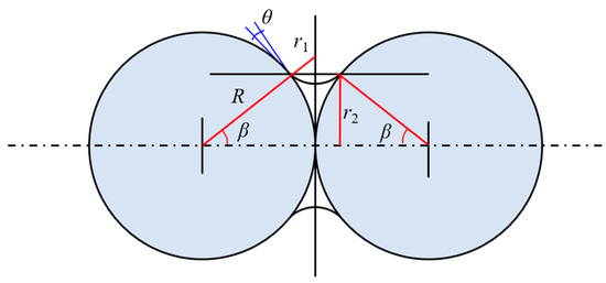
Figure 1.
Schematic diagram of a liquid bridge between two cuttings particles. The bridge represents the cohesive force generated by a polymer or fluid film between particles, which contributes to bed stability.
2.2.4. Interlocking Force
Due to the irregular surface morphology of cuttings particles, which is not smooth, there are protrusions and unevenness. When rock debris accumulates in steep well sections, there is a tendency for the rock cuttings bed to slide downward [34]. That is, there is relative movement between the “layers” of the rock cuttings bed, and there are multiple points of contact on the surface of rock cuttings particles. Interlocking occurs in the uneven areas (as shown in Figure 2). The microscopic interlocking between particles hinders the interlayer movement of the rock cuttings bed, which is the interparticle interlocking force, FH.
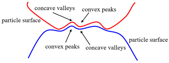
Figure 2.
Surface interlocking among irregularly shaped cuttings particles. The figure illustrates how angularity and surface roughness increase mechanical resistance to sliding or rolling.
2.2.5. Buoyant Force
Particles on the average cuttings bed surface experience their own gravity. Additionally, due to the presence of drilling fluid in the wellbore, cuttings also experience buoyancy from the drilling fluid. The combined effect of these two forces is termed buoyancy, acting vertically downward:
where ρs and ρf are particle and fluid densities, respectively, and g is gravitational acceleration:
2.2.6. Bonding Force (Cohesive Force)
The bonding or cohesive force among particles is enhanced by bentonite additives and formation clays, particularly under low water content or high compaction. This force is modeled as follows:
where ζc is the bonding coefficient, γʹ is the actual dry bulk density of cuttings, γʹc is the reference stable dry bulk density, and mʹ is a dimensionless empirical constant.
2.2.7. Workflow of the Study
The overall research workflow can be summarized as follows:
- Model development: establishment of theoretical models for particle settling and repose angle in non-Newtonian fluids.
- Parameter derivation and closure: identification of governing parameters incorporating particle size and rheological properties.
- Model calibration: adjustment of model coefficients using controlled laboratory data.
- Experimental validation: laboratory experiments to compare theoretical predictions with measured settling behavior.
- Application perspective: interpretation of the results for field-scale drilling fluid systems and hole-cleaning strategies.
3. Establishment of the Prediction Model for the Repose Angle of Cuttings Bed
In highly inclined well sections—such as horizontal wells and extended-reach wells—the accumulation of cuttings along the borehole wall poses severe operational and cleaning challenges. When the inclination angle of the wellbore axis relative to the horizontal exceeds the repose angle of the cuttings bed, the axial gravitational component acting on the particles surpasses the available resistive forces, leading to sliding or rolling movement of the accumulated cuttings. To describe this behavior quantitatively, a theoretical model for predicting the sliding and rolling repose angles is developed. However, existing formulations typically lack comprehensive derivation, validation, and discussion regarding physical assumptions, applicability, and limitations.
This section constructs the prediction model under the following simplifying assumptions:
- Cuttings particles on the average bed surface are densely and uniformly distributed.
- Particle sizes are uniform.
- The cuttings bed surface exhibits homogeneous compaction.
- Particles are idealized as spheres.
- Only the topmost particle layer is considered for movement (sliding or rolling).
3.1. Sliding Repose Angle Model for Cuttings Beds
When particles slide on the bed surface, they are subjected to macroscopic forces, such as gravity and cohesive bonding, and microscale forces, including van der Waals, electrostatic, and capillary bridge forces. Force analysis is performed on particle 2 in Figure 3, where it is subjected to the following forces: vertical downward buoyancy force FG, bonding force FB, perpendicular to the average cuttings bed surface, and frictional force FF, opposite to the direction of particle sliding. Additionally, particle 2 also experiences microscopic particle contact forces (van der Waals forces, electrostatic forces, and liquid bridge forces) from particles 1 and 3 of equal size (uniformly sized and arranged particles), acting in opposite directions. Therefore, in the x-direction, the resultant force of microscopic particle contact forces is zero and can be disregarded, but the particle interlocking force in the x-direction needs to be considered, along with the microscopic contact force exerted on particle 2 by the average cuttings bed surface.
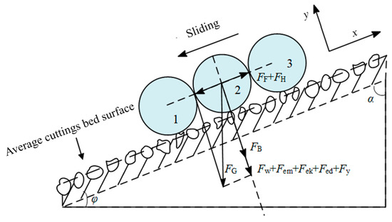
Figure 3.
Schematic diagram of force balance for a sliding particle on a cuttings bed. This force analysis forms the basis of the sliding repose angle model.
Figure 3 provides a visual representation of the force analysis for cuttings particles sliding on the average cuttings bed surface.
The x-direction equilibrium yields the following:
where
Substituting into (8),
Divide both sides by cos φ,
Simplify via trigonometric identities,
In practical analysis, microscale forces are often neglected due to their limited influence on millimeter-scale particles. As such, a simplified form of Equation (14) is as follows:
Solving this using the quadratic formula,
where f is the dimensionless coefficient of friction for the average cuttings bed surface, Ff is the particle frictional force, and FH is the interlocking force.
From Equation (16), it becomes clear that the repose angle φ depends strongly on the effective friction coefficient, which must be calibrated experimentally.
3.2. Estimation of the Friction Coefficient on the Average Cuttings Bed Surface
To determine f, a wedge-insertion model is proposed using two layers of cuttings particles. The detached wedge (with width dp + 2δ and length n(dp + 2δ)) is subjected to bonding, buoyancy, and lateral pressure. Figure 4 illustrates the loading configuration.
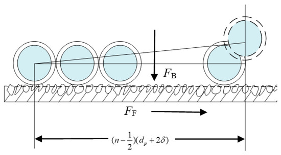
Figure 4.
Force diagram of the wedge insertion model.
Force balance yields the following:
Friction:
Lateral pressure:
where γe is the wet bulk density, and δ is the liquid film thickness (0.001–0.01 mm).
When the particles are in a critical state, force equilibrium yields the following: Ff − Fe = 0. Thus,
From the earlier equilibrium (Equation (10)) and simplifications, we obtain the following:
Combining Equations (19) and (20), Equation (16) transforms into the following:
To proceed, γe and γ′ must be quantified. Based on soil mechanics principles, a conceptual model of post-deposition sediment stratification is introduced (Figure 5).
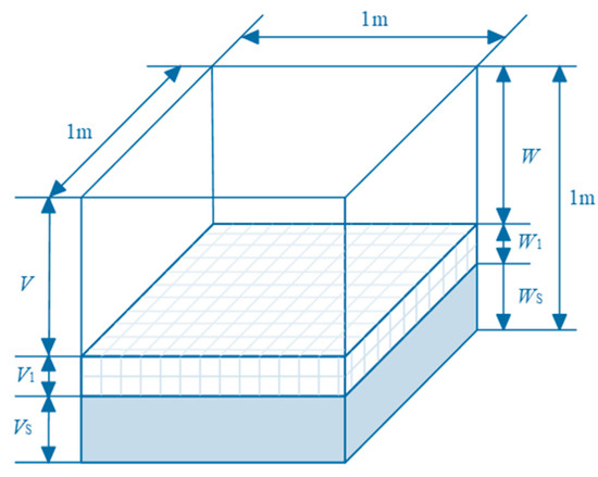
Figure 5.
Schematic of cuttings deposition structure.
The bottom layer represents dense cuttings post-deposition without porosity, with a weight of Ws and a volume of Vs; the top layer represents pure drilling fluid after cuttings deposition, with a weight of W and a volume of V; the middle part represents cuttings with natural porosity after deposition, where the weight of drilling fluid in the pores is W1, and the volume is V1.
The density of turbid drilling fluid is defined as the weight of turbid drilling fluid divided by its volume:
Wet bulk density:
Dry bulk density:
Furthermore, γm is the density of turbid drilling fluid. After drilling stops, cuttings begin to settle. When the concentration of cuttings in the inclined well section is considered very high, meaning the volume of the uppermost liquid layer approaches zero, V → 0 and W → 0, γm = γe, which can be expressed as follows:
As for the dry density, it is calculated using the following formula:
In this equation, d0 is the reference particle size, taken as 1 mm. This allows us to close the system and compute f and ultimately tan φ for the sliding repose model.
3.3. Rolling Repose Angle Model for Cuttings Beds
In addition to sliding downward on the cuttings bed surface, particles can also undergo rolling. During rolling, particles experience their own buoyancy and the cohesive force of the average cuttings bed surface. Additionally, rolling particles experience contact forces from the particles in the layer immediately below them, which are about to separate.
Similar to the simplification made in establishing the model for the angle of repose of sliding cuttings, microscopic contact forces do not need to be considered in the analysis of rolling particles. The force diagram illustrating the forces acting on particles rolling downward on the average cuttings bed surface is depicted in Figure 6.
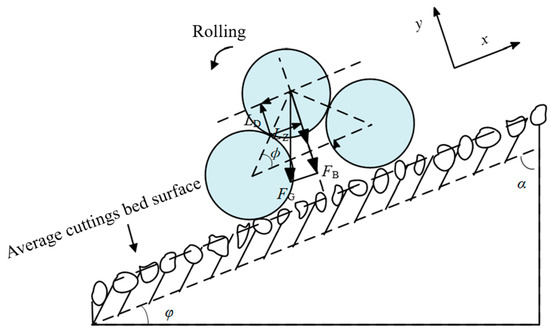
Figure 6.
Force diagram for particles undergoing rolling on a cuttings bed. This representation supports the derivation of the rolling angle prediction model.
Moment equilibrium provides the following:
where LD is the lever arm corresponding to the driving force, LZ is the lever arm corresponding to the resisting force, and ϕ is the angle between the centerlines of adjacent accumulated particles.
Substituting geometric relations,
Simplifying and solving,
This yields the rolling repose angle, which, together with the sliding model, enables comprehensive prediction of cuttings bed stability in deviated wellbores. Equation (31) is based on the critical force balance of particles on the cuttings bed under different transport modes. By analyzing the conditions for particle motion, the corresponding repose angles under various scenarios were calculated.
While the model assumes spherical particles with uniform size and homogeneous compaction, these simplifications facilitate analytical tractability and the identification of dominant mechanisms. In field conditions, cuttings often exhibit irregular shapes, broad particle size distributions, and non-uniform packing densities. Such factors may lead to variations in repose angles beyond those predicted here. Future work could integrate empirical correction factors or numerical simulations to better capture these complexities.
The theoretical framework presented is based on the assumptions of spherical particles, uniform particle size, and homogeneous compaction. These simplifications allow for a tractable analytical solution and focus on the dominant roles of gravitational, buoyant, and cohesive forces. In actual drilling operations, however, cuttings are often irregularly shaped, exhibit a broad particle size distribution, and form beds with non-uniform packing densities. Such conditions can influence repose angles through increased interlocking, variable contact forces, and local compaction effects. As a result, field measurements may yield repose angles that deviate from model predictions. To improve field applicability, the model parameters can be calibrated using site-specific experimental data or adjusted via empirical correction factors derived from numerical simulations or downhole measurements. Therefore, to validate the theoretical framework and to examine the influence of key particle and fluid parameters under controlled conditions, an experimental study was conducted. The following section presents the laboratory setup, measurement procedures, and results.
4. Experimental Study on the Angle of Repose of Rock Cuttings
Building upon the theoretical models developed in Section 3, this chapter presents a detailed experimental investigation aimed at validating the models and analyzing key particle parameters influencing repose behavior.
4.1. Measurement of Repose Angle Under Dry Conditions
The repose angle of rock cuttings refers to the maximum slope angle at which particles naturally accumulate in a stable configuration relative to the horizontal. It is a critical indicator of particle stability in a quiescent state and directly impacts how cuttings deposit and distribute within the wellbore. An accurate understanding of this parameter assists in predicting zones prone to sand bed accumulation.
This study adopts the board removal method (also known as the draw-down method) to measure the static repose angle. In this technique, cuttings are initially confined to one side of a tank by a vertical baffle. As the baffle is slowly lifted, particles are allowed to flow freely and form a naturally deposited slope. The angle between the resulting slope and the horizontal surface is defined as the repose angle, measured using a protractor or angle meter. Each sample is tested at least three times, and the average value is reported.
Four typical rock types were selected—carbonate, shale, granite, and sandstone—each sourced from field operations. The repose angles measured are listed in Table 1.

Table 1.
Repose angles of different types of rock cuttings (dry conditions).
To further analyze particle characteristics, density was first measured via the water displacement method. Samples were then sieved to isolate specific particle size ranges, and the mass of individual particles was recorded.
Statistical results show that sandstone had an average equivalent diameter of 3.11 mm and circularity of 0.746; shale, 5.28 mm and 0.722; granite, 3.23 mm and 0.668; carbonate, 2.98 mm and 0.703. Using regression techniques, a three-dimensional surface fit was applied to relate repose angle, particle size, and circularity.
In addition to the measured data, previously reported experimental values for river sand and glass beads were incorporated to enable comparative analysis. The combined data are summarized in Table 2.
Table 2.
Angles of repose for various types of cuttings.
The repose angles listed in Table 2 were measured experimentally using a standard tilting-box method. For each sample, approximately 500 g of dry, sieved particles were poured into a rectangular box with a smooth base. The box was gradually tilted at a controlled rate of 1°/s until the particle heap began to slide, and the tilt angle at the onset of sliding was recorded as the repose angle.
The fitted relationship indicates that the repose angle is influenced by both equivalent diameter and circularity. The general form of the fitted surface is expressed by Equation (32):
As shown in Figure 7a,b, when holding one parameter constant, the repose angle tends to decrease with increasing circularity or equivalent diameter. This suggests that particle geometry plays a crucial role in the stability and flowability of cuttings beds, especially under non-circulating conditions. The influence of each parameter is discussed below:
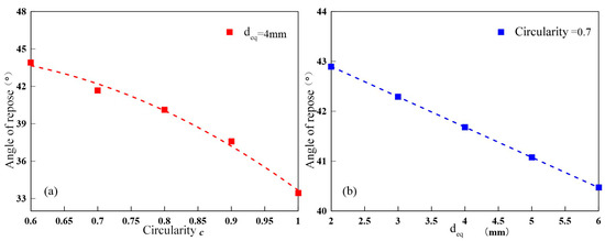
Figure 7.
Relationship between equivalent diameter and circularity of different types of cuttings. (a) deq = 4 mm; (b) c = 0.7. These parameters are used to characterize particle geometry effects in the experiments.
(a) Increasing circularity leads to a reduction in mechanical interlocking and friction among particles, resulting in a lower repose angle. For example, at a constant particle size of 4 mm, increasing circularity from 0.6 to 1.0 causes the repose angle to drop from 45° to 33°.
(b) Increasing the equivalent diameter also correlates negatively with the repose angle, albeit with a smaller effect than circularity. At a constant circularity of 0.7, increasing the particle size from 2 mm to 6 mm leads to a reduction in repose angle from approximately 43° to 40°. The underlying mechanism lies in the reduced contact area and diminished cohesive/frictional interaction among larger particles, promoting easier movement and lower repose angles.
4.2. Measurement of Repose Angle in Inclined Wellbore Simulation
To realistically simulate the sliding behavior of drill cuttings in steeply inclined wellbore sections, this study employs the tilting method to measure the dynamic repose angle of the cuttings bed. Transparent acrylic tubes are used to replicate the geometry of the wellbore, while polyacrylamide (PAM) solutions of various concentrations serve as the drilling fluid. The test materials are screened drill cuttings collected from return flows, with a density ranging from 2.1 to 2.2 g/cm3 and an average particle size of approximately 0.95 mm. Linear PAM with a molecular weight of approximately 12–15 million g/mol was used in this study. A rheometer (MCR 92) was used for all viscosity measurements. A 1% aqueous solution at 25 °C exhibited a viscosity of 200–300 mPa·s. The densities of PAM solutions used are listed in Table 3.
Table 3.
Density of PAM solutions at various concentrations.
During the experiment, the acrylic tube is gradually elevated while the motion of particles is continuously recorded using a high-speed camera. This setup enables precise identification of the onset of motion, allowing for accurate determination of the repose angle.
PAM was selected due to its stable rheology and controllable viscosity, enabling reproducible laboratory measurements. While real drilling fluids may include other additives, the trends observed here are expected to hold for fluids with similar rheological characteristics, though parameter adjustments may be needed for precise field predictions.
The process for measuring the angle of repose of drill cuttings is depicted in Figure 8. It involves several key components: a sand addition tank for storing rock particles, a water tank for holding reserve polyacrylamide (PAM) solution, a control center for managing the precise addition of rock particles and sufficient PAM fluid into the wellbore, and control mechanisms for lifting and lowering the entire experimental setup. A high-speed camera and data acquisition system are employed to record the experimental process and retrieve measurement data from the apparatus.
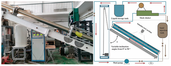
Figure 8.
Photograph of the cuttings bed repose angle measurement apparatus.
Experimental procedure:
- (1)
- Screen the returned drill cuttings using a standard sieve to ensure consistent particle size.
- (2)
- Level the experimental apparatus horizontally and fill the test section with PAM solution.
- (3)
- Load the screened rock particles into the sand feeder.
- (4)
- Start the circulation pump at a low flow rate to fill the acrylic tube with PAM and add particles gradually.
- (5)
- Adjust the flow rate to distribute particles uniformly along the lower tube wall, ensuring a bed thickness of at least 10 times the mean particle diameter (10 dp), and then stop circulation.
- (6)
- Start the lifting mechanism and data acquisition system; gradually tilt one end of the setup.
- (7)
- Observe the surface particle behavior. When movement is detected, halt the lifting and record the inclination angle.
- (8)
- Repeat each test six times to reduce error.
- (9)
- Replace the PAM solution and repeat for all concentrations.
4.3. Experimental Results and Analysis
4.3.1. Repose Angle Test Results
The measured repose angles under different PAM concentrations are presented in Table 4.
Table 4.
Repose angle of cuttings bed at various PAM concentrations.
Based on the data presented in Table 4, the angle of repose of the cuttings bed ranges from 23.9° to 31.7°. Figure 9 illustrates the influence of PAM solution concentration on the angle of repose of the cuttings bed. While individual measured values may show slight decreases with increasing solution concentration, these variations could stem from experimental errors or differences in particle arrangement. However, there is an overall trend indicating that the angle of repose tends to increase with higher solution concentrations.
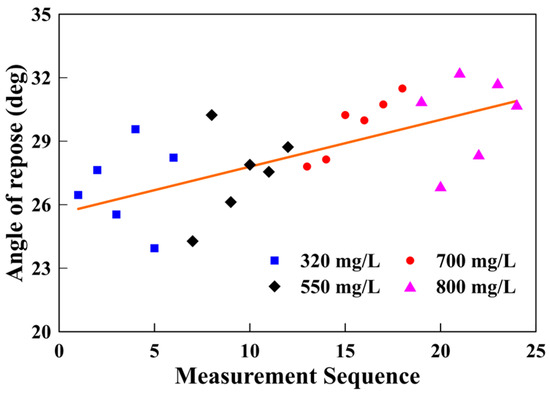
Figure 9.
Variation in repose angle with PAM concentration; data points represent measured repose angles under different polymer concentrations.
The variability in PAM solution concentration correlates with changes in viscosity. In practical drilling operations, higher viscosity of the drilling fluid leads to a larger angle of repose of the bottom hole cuttings bed. This relationship is reflected in Formula (7), which accounts for changes in the correlation coefficient and variations in the thickness of the liquid film on the particle surfaces.
This correlation is attributed to the influence of PAM viscosity on liquid film thickness and interparticle adhesion. According to the theoretical model, friction coefficient discrepancies observed in the calculation using Equations (19) and (20) prompted a correction using liquid film thickness parameters. The modified formulation is as follows:
Transforming the above equation, we obtain the following:
where λ and η represent correction factors for the liquid film, where the range of values for η is between 0.998 and 1.048.
According to the calculation model for the cuttings bed sliding angle of repose and the wedging model proposed in this paper, the correction factor for the liquid film thickness of rock particles, calculated from Equation (34), ranges between 0.974 and 1.618. Average values derived from multiple measurements under various PAM solution concentrations were used to determine these correction factors, which were subsequently applied to calculate the liquid film thickness on particle surfaces. As a result, the calculated cuttings bed sliding angles of repose were determined to be 24.2°, 25.8°, 27.1°, and 28.5° for PAM concentrations of 320 mg/L, 550 mg/L, 700 mg/L, and 800 mg/L, respectively. Experimental average values yielded 26.9°, 27.5°, 29.7°, and 30.2° for the same concentrations. While theoretical values tend to be more conservative compared to experimental findings, they hold significant practical value in ensuring safe drilling operations.
Studies indicate that, for viscous particles with sizes exceeding 1 mm, the impact of cohesive forces on the angle of repose diminishes significantly. This reduction is primarily due to the decreased ratio of cohesive forces to gravitational forces, as illustrated in Figure 10. At this stage, when the cohesive force FB approaches zero, Equation (21) simplifies to the following:
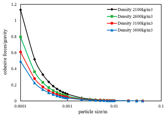
Figure 10.
Ratio of bonding force to gravity as a function of particle size.
Figure 10 illustrates that the bonding force decreases as the size of cuttings increases, accompanied by a reduction in the ratio of bonding force to gravity. For cuttings with a size of 1 mm, the maximum bonding force to gravity ratio (with a cutting density of 2100 kg/m3) is approximately 0.085. Additionally, denser cutting densities result in smaller bonding force to gravity ratios at the same particle size. This suggests that, for denser cutting particles, bonding forces become negligible when calculating the static angle of cutting beds. Therefore, the accumulation of denser cutting particles in high-angle well sections can be treated similarly to the accumulation of loose particles.
4.3.2. Rolling Model Analysis
Observations show that, when rock particles roll from the average cuttings bed surface, the rolling angle varies within the range of 0 to π/3. Different values of φ were considered, and the variation curve of the static rolling angle with particle size is depicted in Figure 11 and Figure 12. Figure 11 illustrates the calculation results when the “±” in Equation (34) is taken as “+”, while Figure 12 shows the results when taken as “−”. The trend of the static angle with particle size exhibits completely opposite variations between the two scenarios.
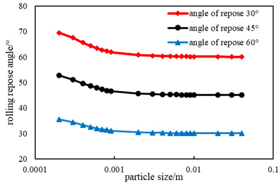
Figure 11.
Predicted repose angle using positive root in Equation (34).
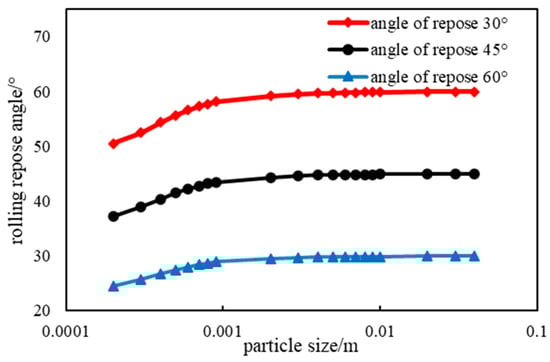
Figure 12.
Predicted repose angle using negative root in Equation (34).
Excluding fine particles (generally less than 0.1 mm) and plastic sands, the static angle of rough surface particles (typically with particle sizes greater than 0.1 mm and less than 40 mm) generally increases with increasing particle size. Therefore, based on the calculation results, choosing “−” in Equation (34) as shown in Figure 12 appears to more accurately reflect reality. A similar rationale applies to the sign in Equation (21), which is also taken as negative, although this is not elaborated further.
As shown in Figure 12, for the same particle size, smaller angle values indicate a looser particle arrangement and larger static rolling angles. As particle size increases under similar arrangements, static rolling angles also increase but tend to stabilize when the particle size exceeds 1 mm. Specifically, when φ = 60°, the particle arrangement is most compact, resulting in a minimal static rolling angle. With further increases in particle size, the static angle stabilizes around 30°.
4.4. Study Limitations
This study, while providing valuable insights into the repose behavior of drill cuttings in inclined wellbore environments, has several limitations that should be considered:
1. Range of Angles: The experimental analysis focused primarily on a limited range of angles for wellbore deviation. As a result, the findings may not fully capture the behavior of cuttings in wells with deviations outside the tested range. Further research should investigate the impact of steeper wellbore angles on cuttings deposition and repose behavior.
2. Drilling Fluid Used: The drilling fluid used in the experiments was limited to a specific composition, which may not represent the wide variety of fluids employed in field conditions. Different fluid properties, such as viscosity and rheology, could affect cuttings transport and deposition, and future studies should explore a broader range of drilling fluid types to enhance the model’s applicability.
3. Particle Size and Shape: This study used spherical particles for simplicity and controlled experimentation. However, real drill cuttings often exhibit irregular shapes and sizes, which may influence the repose angle and bed morphology differently than spherical particles. Further research should incorporate non-spherical cuttings to improve the model’s accuracy in real-world scenarios.
4. Laboratory-Scale Conditions: The experiments were conducted under laboratory-scale conditions, which may not fully replicate the complexities and dynamics present in field-scale drilling operations. The effects of high-pressure, high-temperature environments, as well as other field-specific factors, were not considered in this study and warrant future exploration.
5. Conclusions
This study integrates theoretical modeling with experimental analysis to systematically characterize the repose behavior of rock cuttings in inclined wellbore environments. The main conclusions are as follows:
- (1)
- In highly deviated sections of horizontal wells, the macroscopic forces—namely, buoyancy and cohesive forces—play a dominant role in determining the repose angle of cuttings particles. Given the particle size distribution typically observed, microscopic forces, such as van der Waals, image, and capillary bridge forces, can reasonably be neglected.
- (2)
- A comprehensive force analysis of representative particles on the cuttings bed surface was conducted. Predictive models for both the sliding and rolling repose angles were derived. These models incorporate principles from soil mechanics, allowing for the estimation of sliding friction coefficients and bulk densities of cuttings, thereby enhancing model precision.
- (3)
- Indoor experiments were carried out to calibrate empirical parameters in the sliding repose angle model. Results confirm that, for particles of similar size but higher density, cohesive forces have a negligible influence on repose angle determination.
- (4)
- Experimental results showed that the repose angle of cuttings beds ranges between approximately 23.9° and 31.7°. Both PAM concentration and particle size exert a significant influence on repose angle through their effect on cohesive interactions. Meanwhile, the rolling repose angle was found to stabilize within 25° to 30°, offering further validation of the theoretical framework and practical guidance for downhole tool deployment.
- (5)
- The modeling framework and quantified repose angle ranges obtained in this study can be directly used to improve hole cleaning strategies in field operations. In particular, the results can guide the selection of drilling fluid properties (e.g., polymer concentration) and inform the design of mechanical cleaning tools to maintain cuttings bed stability. Predictive models allow engineers to estimate critical operating parameters for different wellbore inclinations and particle conditions, enabling more targeted adjustments during extended-reach and directional drilling.
At the same time, it should be noted that the present study is based on laboratory-scale experiments with spherical particles and thus does not fully capture the effects of particle irregularity or field-scale complexity.
Future Work:
- (1)
- Expanding the model to account for non-spherical particles, which more accurately represent cuttings encountered in field operations.
- (2)
- Refining the model for use with more concentrated suspensions, considering the impact of higher particle concentrations on repose behavior.
- (3)
- Conducting validation of the developed models under actual field drilling conditions, which will provide further insights into their practical applicability and potential adjustments needed for specific wellbore scenarios.
Author Contributions
Data curation, H.W. and C.L.; Investigation, H.Z.; Methodology, H.Z.; Validation, Y.L.; Writing—original draft, L.T. and J.Q. All authors have read and agreed to the published version of the manuscript.
Funding
This research was funded by the 2023 Open Fund of the Sinopec Key Laboratory of Drilling Completion and Fracturing of Shale Oil and Gas (project title: Study on Cuttings Transport Mechanism and Hole Cleaning Performance Evaluation in Horizontal Wells for Shale Oil and Gas) and by the Hainan Provincial Joint Project of Sanya Yazhou Bay Science and Technology City (Grant No. 2021CXLH0028).
Data Availability Statement
The original contributions presented in this study are included in the article. Further inquiries can be directed to the corresponding author.
Conflicts of Interest
Authors Hui Zhang and Heng Wang were employed by the SINOPEC Research Institute of Petroleum Engineering Co., Ltd. The remaining authors declare that the research was conducted in the absence of any commercial or financial relationships that could be construed as a potential conflict of interest.
References
- Al-Malki, M.; Mahmoud, A.A.; Elkatatny, S. Performance of the Hole Cleaning Factor in Predicting the Hole Cleaning Conditions in Vertical and Deviated Wells: Real Case Studies. Arab. J. Sci. Eng. 2023, 48, 17119–17127. [Google Scholar] [CrossRef]
- Peng, G. Fracture Propagation Laws of Staged Hydraulic Fracture in Fractured Geothermal Reservoir Based on Phase Field Model. Int. J. Coal Sci. Technol. 2023, 10, 52. [Google Scholar] [CrossRef]
- Elmgerbi, A.; Les, B.; Ashena, R.; Atkin, T. A Practical Decision Tool to Evaluate and Rank Potential Solutions for Expected Downhole Drilling Problems During the Well-planning Phase. J. Inst. Eng. Ser. D 2022, 103, 25–36. [Google Scholar] [CrossRef]
- Khanal, M.; Elmouttie, M.; Adhikary, D. Effects of Particle Shapes to Achieve Angle of Repose and Force Displacement Behaviour on Granular Assembly. Adv. Powder Technol. 2017, 28, 1972–1976. [Google Scholar] [CrossRef]
- Yan, T.; Qu, J.; Sun, X.; Li, Z.; Li, W. Investigation on Horizontal and Deviated Wellbore Cleanout by Hole Cleaning Device Using CFD Approach. Energy Sci. Eng. 2019, 7, 1292–1305. [Google Scholar] [CrossRef]
- Song, X.Z.; Li, G.S.; Huang, Z.W.; Wang, H.Z.; Tian, S.C.; Shi, H.Z. Experimental Study on Horizontal Wellbore Cleanout by Rotating Jets. J. Pet. Sci. Eng. 2010, 75, 71–76. [Google Scholar] [CrossRef]
- Li, Y.; Peng, G.; Tang, J.; Zhang, J.; Zhao, W.; Liu, B.; Pan, Y. Thermo-Hydro-Mechanical Coupling Simulation for Fracture Propagation in CO2 Fracturing Based on Phase-Field Model. Energy 2023, 284, 128629. [Google Scholar] [CrossRef]
- Li, X.; Zhang, J.; Tang, X.; Mao, G.; Wang, P. Study on Wellbore Temperature of Riserless Mud Recovery System by CFD Approach and Numerical Calculation. Petroleum 2020, 6, 163–169. [Google Scholar] [CrossRef]
- Dabiri Atashbeyk, M.; Shahbazi, K.; Fattahi, M. Pressure Profile Estimation through CFD in UBD Operation Considering with Influx to Wellbore. Iran. J. Chem. Chem. Eng. 2018, 37, 271–283. [Google Scholar]
- Ghazanfari, V.; Imani, M.; Shadman, M.M.; Amini, Y.; Zahakifar, F. Numerical Study on the Thermal Performance of the Shell and Tube Heat Exchanger Using Twisted Tubes and Al2O3 Nanoparticles. Prog. Nucl. Energy 2023, 155, 104526. [Google Scholar] [CrossRef]
- Kristiansen, T.G.; Bauer, A.; Guida, A.; Bonin, C. A Troublesome Well Section: The Rock Mechanics Analysis. In Proceedings of the SPE Norway Subsurface Conference, Bergen, Norway, 27 April 2022. SPE-209546-MS. [Google Scholar] [CrossRef]
- Fallah, A.H.; Gu, Q.; Saini, G.; Chen, D.; Ashok, P.; Van Oort, E.; Vajargah, A.K. Hole Cleaning Case Studies Analyzed with a Transient Cuttings TransportModel. In Proceedings of the SPE Annual Technical Conference and Exhibition, Online, 27–29 October 2020. SPE-201461-MS. [Google Scholar] [CrossRef]
- Hirpa, M.M.; Kuru, E. Hole Cleaning in Horizontal Wells Using Viscoelastic Fluids: An Experimental Study of Drilling-Fluid Properties on the Bed-Erosion Dynamics. SPE J. 2020, 25, 2178–2193. [Google Scholar] [CrossRef]
- Skenderija, J.; Koulidis, A.; Sanchez, D.L.; Ahmed, S. Advanced Hole Cleaning in Horizontal Wells: Experimental Investigation Supported by a Downhole Clamp-On Tool. In Proceedings of the Middle East Oil, Gas and Geosciences Show, Manama, Bahrain, 19–21 February 2023. SPE-213675-MS. [Google Scholar] [CrossRef]
- Mendez, M.; Ahmed, R.; Karami, H.; Nasser, M.; Hussein, I.; Garcia, S.; Gonzalez, A. Applications of Machine Learning Methods to Predict Hole Cleaning in Horizontal and Highly Deviated Wells. In Proceedings of the SPE/ICoTA Well Intervention Conference and Exhibition, The Woodlands, TX, USA, 21–22 March 2023. SPE-212912-MS. [Google Scholar] [CrossRef]
- Mahmoud, H.; Alhajabdalla, M.; Nasser, M.S.; Hussein, I.A.; Ahmed, R.; Karami, H. Settling Behavior of Fine Cuttings in Fiber-Containing Polyanionic Fluids for Drilling and Hole Cleaning Application. J. Pet. Sci. Eng. 2021, 199, 108337. [Google Scholar] [CrossRef]
- Abbas, A.K.; Alsaba, M.T.; Al Dushaishi, M.F. Comprehensive Experimental Investigation of Hole Cleaning Performance in Horizontal Wells Including the Effects of Drill String Eccentricity, Pipe Rotation, and Cuttings Size. J. Energy Resour. Technol. 2022, 144, 063006. [Google Scholar] [CrossRef]
- Sun, X.; Yao, D.; Qu, J.; Sun, S.; Qin, Z.; Tao, L.; Zhao, Y. A Novel Transient Hole Cleaning Algorithm for Horizontal Wells Based on Drift-Flux Model. Geoenergy Sci. Eng. 2024, 233, 212517. [Google Scholar] [CrossRef]
- Beakawi Al-Hashemi, H.M.; Baghabra Al-Amoudi, O.S. A Review on the Angle of Repose of Granular Materials. Powder Technol. 2018, 330, 397–417. [Google Scholar] [CrossRef]
- Chen, H.; Zhao, S.; Zhou, X. DEM Investigation of Angle of Repose for Super-Ellipsoidal Particles. Particuology 2020, 50, 53–66. [Google Scholar] [CrossRef]
- Li, P.; Ucgul, M.; Lee, S.H.; Saunders, C. A New Approach for the Automatic Measurement of the Angle of Repose of Granular Materials with Maximal Least Square Using Digital Image Processing. Comput. Electron. Agric. 2020, 172, 105356. [Google Scholar] [CrossRef]
- Tikhonov, V.S.; Liapidevskii, V.Y.; Bukashkina, O.S. Three-Layer Nonstationary Model of Cuttings Transport in Oil Wells. Geoenergy Sci. Eng. 2023, 225, 211617. [Google Scholar] [CrossRef]
- Zhao, J.; Huang, W.; Gao, D. Interaction between Pipe Rotation and Cuttings Transport in Extended-Reach Drilling: Mechanism, Model, and Applications. SPE J. 2024, 29, 2857–2876. [Google Scholar] [CrossRef]
- Mao, L.; Yang, P.; Cai, M. Study on Dynamic Transport Characteristics of Cuttings during Drilling and Washing of Long Horizontal Wells. Pet. Sci. Technol. 2023, 42, 3915–3943. [Google Scholar] [CrossRef]
- Qu, J.; Zhu, H.; Sun, X.; Yan, T. Influence of Drilling Fluid Rheology on Hole Cleaning: A Comprehensive Review. Geoenergy Sci. Eng. 2025, 254, 214030. [Google Scholar] [CrossRef]
- Ren, J.; Lu, S.; Shen, J.; Yu, C. Electrostatic Dispersion of Fine Particles in the Air. Powder Technol. 2001, 120, 187–193. [Google Scholar] [CrossRef]
- Dai, L.; Sorkin, V.; Vastola, G.; Zhang, Y.W. Dynamics Calibration of Particle Sandpile Packing Characteristics via Discrete Element Method. Powder Technol. 2019, 347, 220–226. [Google Scholar] [CrossRef]
- Ren, J.; Lu, S.; Shen, J.; Yu, C. Research on the Composite Dispersion of Ultra Fine Powder in the Air. Mater. Chem. Phys. 2001, 69, 204–209. [Google Scholar] [CrossRef]
- Mehtat, A.; Barker1, G.C. The Dynamics of Sand. Rep. Prog. Phys. 1994, 57, 383. [Google Scholar] [CrossRef]
- Wei, H.; Tang, X.; Ge, Y.; Li, M.; Saxén, H.; Yu, Y. Numerical and Experimental Studies of the Effect of Iron Ore Particle Shape on Repose Angle and Porosity of a Heap. Powder Technol. 2019, 353, 526–534. [Google Scholar] [CrossRef]
- Rackl, M.; Grötsch, F.E.; Rusch, M.; Fottner, J. Qualitative and Quantitative Assessment of 3D-Scanned Bulk Solid Heap Data. Powder Technol. 2017, 321, 105–118. [Google Scholar] [CrossRef]
- Ferreira, I.S.B.; Peruchi, R.S.; Fernandes, N.J.; Rotella Junior, P. Measurement System Analysis in Angle of Repose of Fertilizers with Distinct Granulometries. Measurement 2021, 170, 108681. [Google Scholar] [CrossRef]
- Li, C.; Honeyands, T.; O’Dea, D.; Moreno-Atanasio, R. The Angle of Repose and Size Segregation of Iron Ore Granules: DEM Analysis and Experimental Investigation. Powder Technol. 2017, 320, 257–272. [Google Scholar] [CrossRef]
- Deng, Z.; Smolyanitsky, A.; Li, Q.; Feng, X.Q.; Cannara, R.J. Adhesion-Dependent Negative Friction Coefficient on Chemically Modified Graphite at the Nanoscale. Nat. Mater. 2012, 11, 1032–1037. [Google Scholar] [CrossRef]
Disclaimer/Publisher’s Note: The statements, opinions and data contained in all publications are solely those of the individual author(s) and contributor(s) and not of MDPI and/or the editor(s). MDPI and/or the editor(s) disclaim responsibility for any injury to people or property resulting from any ideas, methods, instructions or products referred to in the content. |
© 2025 by the authors. Licensee MDPI, Basel, Switzerland. This article is an open access article distributed under the terms and conditions of the Creative Commons Attribution (CC BY) license (https://creativecommons.org/licenses/by/4.0/).