Abstract
This study focuses on investigating the damage characteristics and mechanisms of Slickwo clean fracturing fluid to the reservoir by using the deep coal seam in the Yan’an gas field as the research subject. During the experiment, fracturing fluids with varying A content were employed to displace coal and rock cores. The impact of these fluids on the permeability and pore structure of coal and rock was analyzed using a combination of nuclear magnetic resonance and high-pressure mercury injection technology. The findings indicate that the permeability damage rates of cores Y-1 and Y-2 post-displacement are 48.4% and 53.6% correspondingly, with the damage worsening as the agent A content increases. NMR data reveals that the fracturing fluid exhibits the highest retention in small pores, followed by medium-sized pores, and the least in large pores. The rise in agent A content enhanced the retention degree in individual pore throats and overall, increasing from 62.24% to 68.74%. The escalation in agent A content results in higher macromolecular residues, causing seepage channel blockages and enhancing the adsorption properties between fracturing fluid and coal rock. This phenomenon leads to inadequate backflow, primarily in smaller apertures. Simultaneously, the interaction between the gel breaker and clay minerals triggers particle migration, blockage, and expansion, consequently diminishing the permeability of coal and rock and inducing specific damages.
1. Introduction
Being a crucial unconventional natural gas resource, global reserves range from 84.23 to 258.21 × 10¹² m3, emphasizing the vital importance of its efficient development in optimizing the energy mix [1]. Hard coal is extracted from deeper and deeper coal seams every year. For example, from 2000 to 2017, the average depth of coal extraction in the upper Silesian coal basin increased from 600 m to 770 m, and the underground coal mining depth is still increasing at a rate of about 5–8 m per year [2]. Nevertheless, coal reservoirs typically exhibit low permeability and high adsorption properties, necessitating hydraulic fracturing for achieving economic feasibility. During fracturing operations, the interplay between fracturing fluid and coal-rock formations triggers various reservoir damage issues, leading to approximately 30% to 85% of fractured wells falling short of anticipated production levels [3].
Hydraulic fracturing serves as the primary stimulation technique for extracting coalbed methane in deep coal seams. Reservoirs in deep coal seams are susceptible to working fluids during fracturing operations. High-temperature, high-pressure conditions, intense geostress, weak reservoir properties, and substantial heterogeneity pose significant challenges to the current fracturing technology system in terms of its applicability and efficiency [4,5,6]. Through evaluating the fundamental performance of various fracturing fluids, it is concluded that the damage inflicted by these fluids on coalbed methane reservoirs primarily stems from solid particle blockage, particle migration blockage, and water lock issues [7,8,9,10]. Following exposure to various fracturing fluids, the permeability of coal cores within coalbed methane reservoirs decreases to varying extents. Linear gel fracturing fluid stands out as the most detrimental to these reservoirs [11,12], whereas clean fracturing fluid, with its low residue, easy flowback, minimal reservoir damage, favorable rheological properties, and high fluid efficiency, proves effective in well fracturing processes [13,14,15,16,17].
Li et al. employed the mercury intrusion method (MIP) and low-field nuclear magnetic resonance (NMR) data for a quantitative analysis of the pore-fracture structure and its fractal characteristics. Two distinct permeability models are introduced to estimate coal permeability based on MIP and LF NMR, with a detailed discussion on the impact of pore and micro-fractures on coal permeability [18]. Zuo et al. utilized the low-temperature N2 adsorption method and scanning electron microscope (SEM) for coal sample characterization, conducting gas adsorption/desorption tests to systematically examine high, medium, and low-rank coal samples pre and post clean fracturing fluid treatment. It was observed that after clean fracturing fluid treatment, the desorption rate of mid and high-rank coal samples increased, while that of low-rank coal samples decreased [19]. Liu et al. proposed a multi-scale evaluation method for assessing working fluid filtration damage by incorporating desorption, diffusion, and seepage factors, applying it to evaluate coal and rock reservoirs in the Qinshui Basin, China. Results indicate that the reduction in effective channels and the rise in gas transmission resistance are responsible for the formation damage from working fluid filtrate due to water blockage, mineral expansion and blockage, and heightened stress sensitivity [20]. Lu et al. conducted experimental research on the impacts of water and viscoelastic surfactant fracturing fluid on the composition, pore structure, and permeability of coal samples at varying burial depths. The results demonstrated that viscoelastic surfactant fracturing fluid could diminish the presence of clay minerals prone to obstructing coal pores and fractures, leading to a notable increase in cumulative pore volume and permeability of the treated coal samples [21]. Wu et al. employed scanning electron microscopy, X-ray diffraction analysis, and Micro-CT imaging for a comprehensive investigation into the pore-throat structure, mineral composition, fluid properties, and wettability of the No.3 and No.15 coal seams in the Qinshui Basin of northern China, elucidating the potential factors contributing to reservoir damage from liquid intrusion [22]. Liu et al. characterized the mercury injection curve using the mercury injection method (MIP), revealing that from bright coal to dark coal, pore connectivity deteriorates, and the uniformity of pore and throat distribution decreases [23].
Slickwo Clean Fracturing Fluid is a specialized fracturing fluid designed specifically for coal seam rocks, comprising a bio-grafted polymer and a surfactant, typically derived from two core components, Slickwo-A and Slickwo-B. Slickwo-A is a chitin graft polymer resulting from the cerium ion-induced graft copolymerization of methacrylamide and chitin. Increasing the degree of methyl methacrylate grafting enhances intramolecular hydrogen bonding, while saturating hydrogen bonding from oxygen atoms weakens and disrupts intermolecular bonds. This adjustment in hydrogen bonding equilibrium significantly boosts the dissolution rate of the chitin graft copolymer (soluble within 30 s). Post-dissolution, the polymer aggregates through supramolecular self-assembly, elevating the apparent molecular weight and enhancing solution viscosity. With increasing concentration, aggregate density and structural strength accumulate, forming a continuous spatial network in the solution, leading to a sharp viscosity increase. As a nonionic surfactant, Slickwo-B not only optimizes system dispersion uniformity but also enhances the dissolution kinetics of Slickwo-A, generating a high-viscosity fluid with outstanding viscoelastic properties, thereby enhancing its proppant-carrying capacity significantly. This fracturing fluid system is entirely based on bio-components, boasting an excellent neutral pH value and biodegradability [24].
Hence, a critical aspect in advancing the efficient development technology of coalbed methane lies in the systematic investigation of the impact of Slickwo clean fracturing fluid, along with a thorough analysis of its damage characteristics and formation mechanisms. This research centers on the deep coalbed methane reservoir within the Yan’an gas field, employing nuclear magnetic resonance in conjunction with high-pressure mercury injection techniques to quantitatively assess the extent of reservoir damage caused by various Slickwo clean fracturing fluid systems, thereby enhancing the productivity of coalbed methane reserves.
2. Materials and Methods
2.1. Experimental Materials
Two samples of coal and rock cores from Yan’an gas field are selected as experimental samples, and the basic physical properties of cores are shown in Table 1. We used the Slickwo online fracturing fluid system as the experimental fluid for displacing these coal and rock cores. For the displacement of core Y-1, we prepared fracturing fluid gel breaker sample 1 using 0.4% Slickwo-A and 0.2% Slickwo-B; while for core Y-2, we employed 0.5% Slickwo-A and 0.2% Slickwo-B to prepare fracturing fluid gel breaker sample 2.

Table 1.
Core sample information.
2.2. Experimental Device
The experimental equipment comprises a core holder, ISCO pump, thermostat, pressure gauge, back pressure valve, hand pump, low-field nuclear magnetic resonance (NMR) instrument, high-pressure mercury intrusion instrument, etc. (see Figure 1). The nuclear magnetic resonance instrument utilized in this study is manufactured by Suzhou Xinmai Analytical Instrument Co., Ltd., Suzhou, China with the model being PQ001. The displacement pump model is the ISCO-260D from the United States, featuring a pressure range of 0 to 51.7 MPa, and a double pump continuous flow velocity range of 0.001 to 80 mL/min. All the mentioned equipment is manufactured by Jiangsu Huaxing Petroleum Instrument Co., Ltd., Nantong, China.
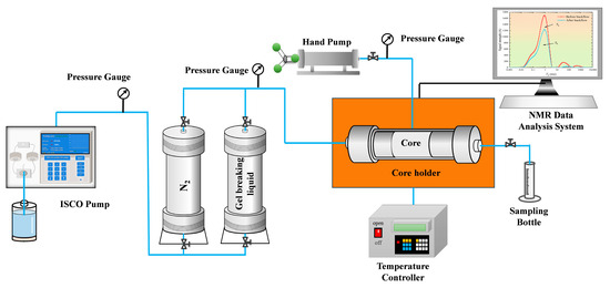
Figure 1.
Schematic diagram of experimental device.
2.3. Experimental Process
The experimental steps of this experiment are as follows:
(1) According to the industry standard, the core is processed into a standard plunger shape, then all the original fluids in the rock sample are cleaned, and two coal rock cores are placed in a drying box, and the drying temperature is set at 55 °C. During the drying process, the quality change in the cores is monitored until the core quality remains unchanged, and the drying is finished.
(2) Utilizing a vernier caliper to measure physical parameters such as length and diameter of the rock sample, inserting the core into the core holder to displace nitrogen forwardly to acquire the initial gas logging permeability, denoted as K1.
(3) Two distinct fracturing fluid and gel breaker systems are employed to displace coal and rock cores in reverse. The displacement rate is 0.1 mL/min, with an injection pressure of 5 MPa, a confining pressure of 6.5 MPa, and a temperature of 80 °C. After 15 PV of displacement, the process is halted while maintaining constant confining pressure and temperature. The fracturing fluid and gel breaker are allowed to react fully with the rock minerals for over 12 h before the core is extracted for nuclear magnetic resonance (NMR) testing.
(4) Re-inserting the core into the core holder after the nuclear magnetic testing and employing high-displacement nitrogen to forwardly displace the core, displacing between 10 PV and 15 PV to ensure complete drainage of fracturing fluid and gel breaker from the core. Subsequently, utilizing parameters set for gas logging permeability in step (2) to evaluate gas logging permeability of the core affected by fracturing fluid gel breaker, obtaining the gas logging permeability K2 tested through nuclear magnetic resonance.
(5) Conducting comprehensive analysis based on the aforementioned gas logging permeability and nuclear magnetic data pre and post flowback to evaluate the extent of damage caused by the clean fracturing fluid to deep coal seams.
2.4. Experimental Principle
Utilizing one-dimensional nuclear magnetic resonance (NMR) technology, this study examines the damage attributes of various Slickwo fracturing fluid systems by assessing pore structure damage data during fracturing fluid injection and flowback. It elucidates alterations in macro permeability and micro pore structure of coal and rock cores pre and post displacement, while evaluating the multiscale damage mechanisms of fracturing fluid on deep coal seam reservoirs.
(1) Damage degree of core macro permeability
In the displacement experiment, the injection and backflow of fracturing fluid induce chemical and physical damage to the core pore structure, primarily stemming from fracturing liquid entrapment, clay mineral swelling and dispersion, solid particle detachment and migration, as well as chemical precipitation. These processes result in degraded physical properties of the core and pore structure blockage [25,26,27]. The permeability damage ratio of coal and rock cores serves as a common indicator for quantifying the macroscopic extent of core damage, with its definition formula presented in Equation (1):
In this formula: DK permeability damage rate, %; K1, initial permeability of core, mD; K2, permeability after core damage, mD.
(2) Microscopic retention degree of fracturing fluid
Low-field nuclear magnetic resonance (NMR) serves as an experimental technique preserving the geometric integrity of rock samples, offering insight into the pore throat characteristics [28,29,30,31]. This technology tracks hydrogen atom and proton movements in hydrocarbons within water and liquid phases. However, the relaxation time (T2) varies significantly among throats saturated with experimental fluid of different sizes. In small throats, the T2 of the experimental fluid is low due to limited hydrogen nuclei interacting with NMR, whereas numerous hydrogen nuclei in larger throats interact with NMR, resulting in higher T2 values. Establishing the relationship between pore size and relaxation time is pivotal in this study.
To assess the extent of fracturing fluid damage, the quantity of fracturing fluid retained in pores is quantitatively evaluated by calculating the area under the T2 spectrum curve from nuclear magnetic resonance scans of various core types. Additionally, the impact of fracturing fluid on diverse reservoir types is assessed based on the retention level of the fluid.
During fracturing fluid flowback, the introduction of N2 into pores creates a gas–liquid interface protrusion, leading to the backflow of stranded fracturing fluid. Simultaneously, this action displaces fracturing fluid within the reservoir deeper, causing a decline in reservoir permeability [32,33,34,35,36]. Utilizing pre- and post-experiment T2 spectra from nuclear magnetic resonance to compute the retention degree, as depicted in Equation (2), enables effective evaluation of the damage attributes of fracturing fluid (Figure 2).
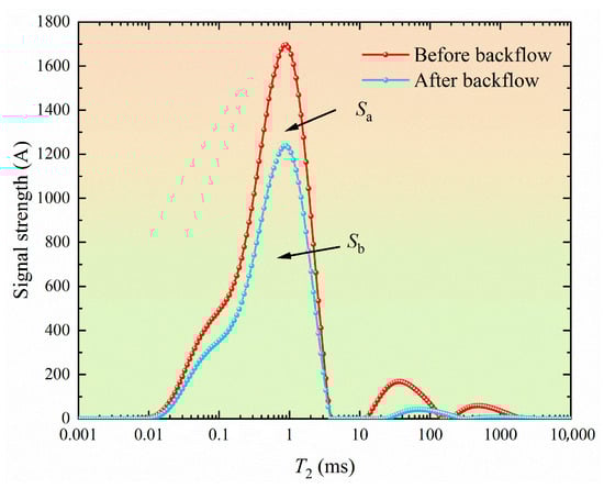
Figure 2.
NMR changes in fracturing fluid before and after gel-breaking fluid backflow.
In Formula (2), I is the retention degree of fracturing fluid; Sa is the total area of NMR T2 spectrogram of core after fracturing fluid displacement; Sb is the total area of NMR T2 spectrogram of core after nitrogen backflow.
(3) Mathematical mechanism of pore throat inversion at different scales
The relaxation rate of a fluid-saturated rock is commonly viewed as resulting from three components: surface area relaxation, volume relaxation, and diffusion relaxation. Due to the significantly shorter transverse volume relaxation time of the fluid compared to the transverse surface relaxation time, and the negligible magnitude of the magnetic field gradient, the terms representing transverse volume relaxation time and magnetic field gradient coefficient can be disregarded when determining the relationship between relaxation time and pore throat radius [37,38].
Due to the intricate nature of the microscopic pore structure within the formation, simplifying the pore structure as spheroid or cylinder alone is inadequate. Consequently, extensive studies correlating NMR with pore structure have led previous researchers to conclude that the T2 spectrum exhibits a power-law relationship with pore radius, represented as the product of pore throat radius and average pore throat ratio. Hence, the relationship equation bridging relaxation time and pore throat radius can be reformulated into Equations (3) and (4):
In Formula (3) and (4), T2 is the relaxation time, μs; r is the throat radius, μm; β is the average pore throat ratio of pores; a and b are constant variables; E is the transverse surface relaxation strength, μm/ms; I is the pore shape factor.
Since the above equation is not directly solvable, intermediate variables are introduced to facilitate its solution. Moreover, by taking the natural logarithm of the equation, a simplified solution for the relationship between final relaxation time and pore throat radius is derived, as depicted in Formula (5). Subsequently, through the resolution of the intermediate variable and the power exponent, the relaxation time distribution of fluid-saturated rocks can be converted into a distribution based on pore radius.
Owing to the intricate and varied pore throat configurations within formation porous media, the high-pressure mercury injection test data fails to accurately depict pore details concerning the throat and isolated pores when the pore throat radius is under the maximum mercury injection pressure. Similarly, the T2 spectrum in nuclear magnetic resonance experiments does not capture information on isolated pores. Additionally, divergences exist in how the two experiments characterize pore information. Therefore, when handling the intermediate variable and power exponent, sampling is limited to the portion aligned well with the cumulative distribution curve of pore throat radii from high-pressure mercury injection tests (Figure 3).
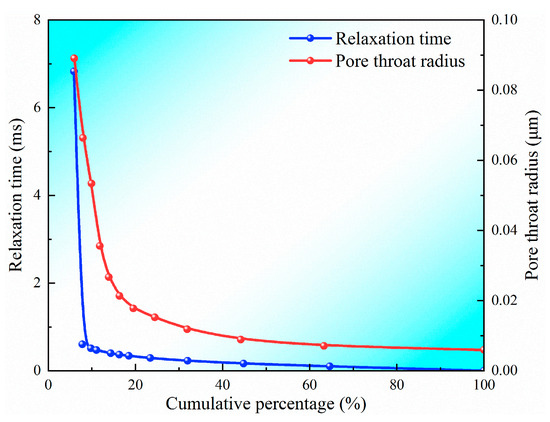
Figure 3.
Cumulative distribution curve of relaxation time and pore throat radius.
Utilizing the least squares method, the parameters are adjusted to find the optimal values for c and n. Subsequently, the minimum values for c and n are determined, thereby establishing the values of these two parameters.
Based on the fitting outcomes, the chosen parameters c and n are 0.000131595 and 0.87986 correspondingly. These values lead to an R2 value of 0.947 for the fitting equation, while the closeness between the fitting line and the experimental data curve signifies the adequacy of the fit. By substituting them into the simplified equation relating relaxation time to pore throat radius, the T2 spectrum can be transformed into a distribution based on pore radii (Figure 4).
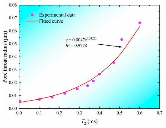
Figure 4.
Function fitting of pore throat radius and T2 relaxation time.
3. Results and Discussion
3.1. Characteristics of Coal and Rock Samples
Scanning electron microscope analysis reveals that core Y-1 exhibits extensive micro-cracks and pore systems. Moreover, the fracture surface of the sample displays a distinctive conchoidal morphology, with identifiable clay minerals interspersed unevenly or in clusters amidst coal, rock organic matter, and inorganic mineral particles. In contrast, core Y-2 showcases a tightly packed structure with evident banding. Additionally, a systematic arrangement of clay minerals in strips and fine layers is observed locally, predominantly comprising flaky kaolinite, while localized regions exhibit micro-cracks (refer to Figure 5).
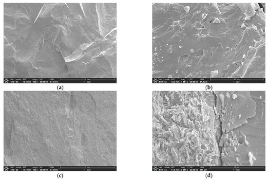
Figure 5.
Scanning electron microscope image of the coal and rock core, (a) Core Y-1 under ×100 magnification; (b) Core Y-1 under ×4884 magnification; (c) Core Y-2 under ×100 magnification; (d) Core Y-2 under ×3896 magnification.
3.2. Damage to the Matrix Caused by Fracturing Fluid
The impact of fracturing fluid on coal and rock matrices was assessed using actual rock samples Y-1 and Y-2. This evaluation involved measuring the initial gas permeability of the samples and their permeability post displacement by various fracturing fluids (refer to Table 2).
Table 2.
Gas-measured permeability of cores.
Core Y-1 exhibits an original gas logging permeability of 3.2241 mD, which decreases to 1.6643 mD after the fracturing fluid displaces due to gel breaking, resulting in a core damage rate of 48.4%. For core Y-2, the initial gas logging permeability is 0.8073 mD, which reduces to 0.3739 mD post fracturing fluid displacement following gel breaking, leading to a core damage rate of 53.6%.
Comparison of the permeability changes in the two samples reveals an increase in damage degree from 48.4% to 53.6% with the introduction of agent A. Following the injection of fracturing fluid and gel breaker into the core, the augmented presence of agent A results in the formation of residual material that struggles to traverse the narrower pore throats, causing localized blockages [39,40,41]. Furthermore, the heightened concentration of agent A amplifies its adsorption onto the surfaces of coal and rock, facilitating easier absorption on the rock pore surfaces. During flowback, the gel breaker encounters increased difficulty returning from the pores, intensifying retention effects that obstruct flow channels, ultimately leading to decreased permeability and escalated damage degree (Refer to Figure 6 and Figure 7).
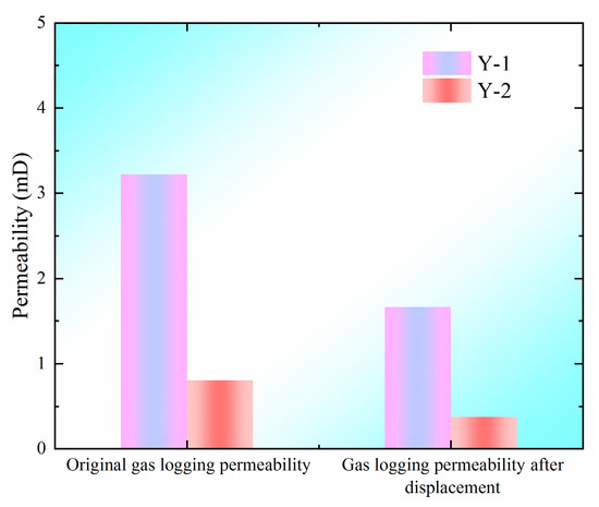
Figure 6.
Illustrates the changes in gas logging permeability before and after the flowback of fracturing fluid and gel breaker.
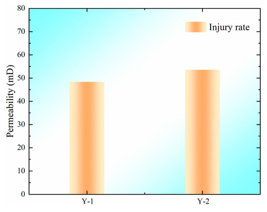
Figure 7.
Depicts the variation in damage rate of the fracturing fluid post gel breaker injection.
3.3. Analysis of Pore Throat Retention Characteristics of Fracturing Fluid with Different Scales Based on NMR
In accordance with a quantitative standard for classifying coal and rock pore throat radii, pores in the block are categorized as small (less than 0.01 μm), medium (0.01–0.1 μm), and large (greater than 0.1 μm). Following this criterion, the experiment establishes a quantitative basis for categorizing pore throat radii sizes (Table 3).
Table 3.
Classification standard of pore throat radius.
Through comparing and analyzing NMR curves of various fracturing fluid systems pre- and post-injection into the core, the distribution pattern of fracturing fluid in different pore and throat scales within coal and rock becomes evident. The curve during injection typically exhibits a tri-modal shape, featuring a prominent peak on the left (representing small apertures), a subdued peak in the middle (indicative of medium apertures), and the smallest peak on the right (representing large apertures), suggesting that the predominant pores in coal and rock are small, with limited development of medium and large pores. Subsequent to flowback, all fracturing fluid systems exhibit a marked signal intensity decline in mesopores and macropores, indicating effective flowback of fluid from these intermediate to large-scale spaces (Figure 8).
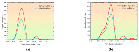
Figure 8.
Diagram of NMR changes in fracturing fluid before and after gel-breaking fluid flowback, (a) Nuclear magnetic change diagram of core Y-1 before and after gel breaker flowback; (b) Nuclear magnetic change diagram of core Y-2 gel breaker before and after flowback.
Table 4 shows the NMR changes in fracturing fluid before and after backflow in coal and rock. The liquid phase retention degree in the small pore of core Y-1 is as high as 65.18%, and that in core Y-2 is 69.81%. The characteristic that the fracturing fluid in the small pore is difficult to be discharged. Medium pore in Y-1 is 18.87% and in Y-2 is 21.63%, with a notable decrease in signal intensity suggesting better flowback efficiency compared to smaller pores. Large pores show the lowest retention rates in Y-1 (3.26%) and Y-2 (3.77%), with the most significant signal intensity drop, indicating effective drainage of fracturing fluid at this scale. Entirety percentages in cores Y-1 and Y-2 are 62.24% and 68.74%, respectively.
Table 4.
Retention degree of different cores.
Figure 9 presents a radar chart illustrating the pore throat retention percentages at various scales post fracturing fluid injection into the core. The addition of agent A in the gel breaker of the fracturing fluid significantly impacts the gel breaker retention across different pore throat scales. With the increase in agent A content, the retention degree of fracturing fluid in the small pore rose from 65.18% to 69.81%, an increase of 4.63%. Specifically, retention in medium pore and large pore increases by 2.76% and 0.51%, respectively. The entirety retention level rises from 62.34% to 68.74%, representing a 6.40% increase. The heightened agent A content in the gel breaker enhances its adsorption properties, hindering complete fracturing fluid discharge. Furthermore, as the fracturing fluid traverses through core pores, smaller pores impede flowback, amplifying retention and causing some core permeability impairment [42,43].
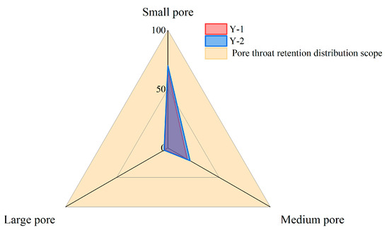
Figure 9.
Radar chart of percentage of retention degree of pore throat at different scales.
3.4. Microscopic Damage Mechanisms of Environmentally Friendly Fracturing Fluids
Upon injection of Fracturing fluid gel breaking fluid into coal and rock formations, the increased agent A content leads to a rise in macromolecular residue generated during the gel breaker process. This blocks the permeability pathways in coal and rock, obstructing fluid flow, inflicting damage, and reducing permeability. Furthermore, the heightened agent A concentration exacerbates its adsorption onto the pore surfaces of coal and rock. During flowback, full recovery of the gel breaker in coal and rock proves challenging, resulting in retention, particularly in small pores, impeding fluid flow and diminishing permeability. As the gel breaker penetrates the pores of coal and rock, interactions with clay minerals ensue, causing particle migration blockages and clay swelling within the pores. This significantly diminishes the volume of flow channels, leading to specific damage to the coal and rock formations [44,45,46,47,48] (Figure 10).
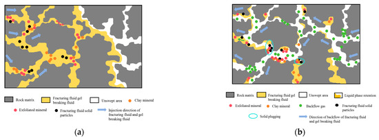
Figure 10.
Microscopic damage mechanism of fracturing fluid, (a) Injection process of fracturing fluid and gel breaking fluid; (b) The backflow process of fracturing fluid and gel breaking fluid.
4. Conclusions
This study focuses on the deep coalbed methane reservoirs in the Yan’an gas field, aiming to characterize their microscopic pore structure features. Based on these characteristics, destructive testing of fracturing fluids and nuclear magnetic resonance (NMR) experiments were conducted. Furthermore, NMR combined with high-pressure mercury intrusion was employed to quantitatively assess the extent of damage caused by different Slickwo clean fracturing fluid systems during their invasion into coal and rock reservoirs and to elucidate the underlying microscopic mechanisms. The following conclusions were drawn:
(1) The coal and rock reservoirs are mainly developed with micropores, and there are a few mesopores, macropores, and fractures. Clay minerals are mixed in the matrix, and clay minerals are often filled or attached at the edges or inside of microcracks and pores. The expansion of these clay minerals will increase the fluidity damage of pores and micro-fractures, and at the same time, during the displacement process of fracturing fluid, clay minerals will migrate and then plug, which will aggravate the matrix damage.
(2) After the 0.4% Slickwo-A and 0.2% Slickwo-B system fracturing fluid is used for displacement, the matrix damage rate of coal and rock reaches 48.4%, and after the 0.5% Slickwo-A and 0.2% Slickwo-B system is used for displacement, the matrix damage rate reaches 53.6%. The damage rate of the core matrix increases with the increase in agent A content.
(3) The NMR curve shows that the retention degree of small holes is the highest, followed by middle holes, and the retention degree of large holes is the lowest in both cores after displacement by fracturing fluid and gel-breaking fluid. With the increase in the content of agent A, the retention degree of micropores increased from 65.18% to 69.81%, mesopores from 18.87% to 21.63%, macropores from 3.26% to 3.77%, and the overall retention degree increased from 62.24% to 68.74%.
(4) With the increase in the content of agent A, the macromolecular residue produced by fracturing fluid is increased, which blocks the permeability channel of coal and rock and hinders the fluid movement. Moreover, the adsorption of macromolecular residues on the pore surface of coal and rock is intensified, leading to insufficient backflow of gel breaker, especially in small pores, which occupy the channel. At the same time, the gel breaker reacts with clay minerals of coal and rock, causing particle migration blockage and clay expansion, reducing the volume of the seepage channel, and eventually leading to the decline of coal and rock permeability.
Author Contributions
Conceptualization, J.W. and C.W.; methodology, A.L.; software, F.Z.; validation, F.Z., Y.L. and L.Y.; formal analysis, A.L.; investigation, Y.J.; resources, J.W.; data curation, A.L.; writing—original draft preparation, F.Z.; writing—review and editing, Y.L.; visualization, L.Y.; supervision, F.Z.; project administration, J.W.; funding acquisition, J.W. and C.W. All authors have read and agreed to the published version of the manuscript.
Funding
This research was supported by the National Natural Science Foundation of China (No.52374041), the Key Research and Development Projects of Shaanxi Province (No.2023-YBGY-306) and the Key Research Project of Shaanxi Provincial Department of Education (No.22JY054).
Data Availability Statement
All data are included in the manuscript.
Acknowledgments
Thanks to all authors for their contributions.
Conflicts of Interest
Authors Jinqiao Wu, Anbang Liu, Fengsan Zhang, Yiting Liu, Le Yan and Yenan Jie were employed by the company Natural gas research institute of Shaanxi Yanchang Petroleum (Group) Co., Ltd. The remaining author declares that the research was conducted in the absence of any commercial or financial relationships that could be construed as a potential conflict of interest.
References
- Feng, G.; Wang, G.; Xie, H.; Hu, Y.; Meng, T.; Li, G. A Review of Exploration and Development Technologies for Coal, Oil, and Natural Gas. Energies 2024, 17, 3600. [Google Scholar] [CrossRef]
- Dreger, M. Methane emissions in selected hard-coal mines of the Upper Silesian Coal Basin in 1997–2016. Geol. Geophys. Environ. 2019, 45, 121–132. [Google Scholar] [CrossRef]
- Huang, Q.; Liu, S.; Cheng, W.; Wang, G. Fracture Permeability Damage and Recovery Behaviors with Fracturing Fluid Treatment of Coal: An Experimental Study. Fuel 2020, 282, 118809. [Google Scholar] [CrossRef]
- Jiang, Z.; Li, Q.; Hu, Q.; Chen, J.; Li, X.; Wang, X.; Xu, Y. Underground Microseismic Monitoring of a Hydraulic Fracturing Operation for CBM Reservoirs in a Coal Mine. Energy Sci. Eng. 2019, 7, 986–999. [Google Scholar] [CrossRef]
- Gao, D.; Bi, Y.; Xian, B. Technical Advances in Well Type and Drilling & Completion for High-Efficient Development of Coalbed Methane in China. Nat. Gas Ind. B 2022, 9, 561–577. [Google Scholar] [CrossRef]
- Li, L.; Liu, D.; Cai, Y.; Wang, Y.; Jia, Q. Coal Structure and Its Implications for Coalbed Methane Exploitation: A Review. Energy Fuels 2021, 35, 86–110. [Google Scholar] [CrossRef]
- Li, C.; Sun, L.; Zhao, Z.; Zhang, J.; Li, Y.; Meng, Y.; Wang, L. A Method for Evaluating Coalbed Methane Reservoir Productivity Considering Drilling Fluid Damage. Energies 2024, 17, 1686. [Google Scholar] [CrossRef]
- Tao, X.; Zheng, Z.; Yu, H.; Liu, H.; Li, Y.; Zhang, J.; Liu, J.; Zheng, L. Internal Blocking and Bonding to Strengthen the Mechanical Properties and Prevent Collapse and Leakage of Fragmented Coalbed Methane (CBM) Reservoirs by Cohesive Drilling Fluids. Geoenergy Sci. Eng. 2024, 241, 213136. [Google Scholar] [CrossRef]
- Huang, W.; Lei, M.; Qiu, Z.; Leong, Y.-K.; Zhong, H.; Zhang, S. Damage Mechanism and Protection Measures of a Coalbed Methane Reservoir in the Zhengzhuang Block. J. Nat. Gas Sci. Eng. 2015, 26, 683–694. [Google Scholar] [CrossRef]
- Pan, J.; Mou, P.; Ju, Y.; Wang, K.; Zhu, Q.; Ge, T.; Yu, K. Micro-Nano-Scale Pore Stimulation of Coalbed Methane Reservoirs Caused by Hydraulic Fracturing Experiments. J. Pet. Sci. Eng. 2022, 214, 110512. [Google Scholar] [CrossRef]
- Wang, F.; Huang, F.; Guan, Y.; Xu, Z. Mitigation of Fracturing Fluid Leak-off and Subsequent Formation Damage Caused by Coal Fine Invasion in Fractures: An Experimental Study. Processes 2024, 12, 1711. [Google Scholar] [CrossRef]
- Lyu, S.; Wang, S.; Li, J.; Chen, X.; Chen, L.; Dong, Q.; Zhang, X.; Huang, P. Massive Hydraulic Fracturing to Control Gas Outbursts in Soft Coal Seams. Rock Mech. Rock. Eng. 2022, 55, 1759–1776. [Google Scholar] [CrossRef]
- Zhou, M.; Yang, X.; Gao, Z.; Wu, X.; Li, L.; Guo, X.; Yang, Y. Preparation and Performance Evaluation of Nanoparticle Modified Clean Fracturing Fluid. Colloids Surf. A Physicochem. Eng. Asp. 2022, 636, 128117. [Google Scholar] [CrossRef]
- Sun, N.; Gao, M.; Liu, J.; Zhao, G.; Ding, F.; You, Q.; Dai, C. A Novel Temperature-Resistant Fracturing Fluid for Tight Oil Reservoirs: CO2-Responsive Clean Fracturing Fluid. Colloids Surf. A Physicochem. Eng. Asp. 2023, 665, 131247. [Google Scholar] [CrossRef]
- Zhao, J.; Fan, J.; Mao, J.; Yang, X.; Zhang, H.; Zhang, W. High Performance Clean Fracturing Fluid Using a New Tri-Cationic Surfactant. Polymers 2018, 10, 535. [Google Scholar] [CrossRef]
- Zhang, W.; Zhang, Q.; Xia, T.; Ji, Q.; Liu, J.; Liu, X.; Wang, L.; Wang, L. Development and Study of a Salt Tolerance Gemini Cationic Viscoelastic Surfactant with Spacer of Neopentyl-Glycol Applied in Seawater-Based Clean Fracturing Fluid. Colloid Polym. Sci. 2025, 303, 547–561. [Google Scholar] [CrossRef]
- Zuo, S.; Wang, C.; Si, J.; Zhang, L.; Tian, F.; Peng, S.; Li, Z. The Effect of Temperature and Ultrasonic Power on the Microstructure Evolution of Coal Modified by Clean Fracturing Fluid: An Experimental Study. Energy 2024, 306, 132436. [Google Scholar] [CrossRef]
- Li, Z.; Liu, D.; Cai, Y.; Wang, Y.; Si, G. Evaluation of Coal Petrophysics Incorporating Fractal Characteristics by Mercury Intrusion Porosimetry and Low-Field NMR. Fuel 2020, 263, 116802. [Google Scholar] [CrossRef]
- Zuo, W.; Zhang, W.; Liu, Y.; Han, H.; Huang, C.; Jiang, W.; Mitri, H. Pore Structure Characteristics and Adsorption and Desorption Capacity of Coal Rock after Exposure to Clean Fracturing Fluid. ACS Omega 2022, 7, 21407–21417. [Google Scholar] [CrossRef]
- Liu, D.; Lin, C.; Guo, B.; Liu, Q.; Ma, F.; Wang, Q.; Wei, C.; Wang, L.; Jia, D. Experimental Evaluation of Working Fluid Damage to Gas Transport in a High-Rank Coalbed Methane Reservoir in the Qinshui Basin, China. ACS Omega 2023, 8, 13733–13740. [Google Scholar] [CrossRef] [PubMed]
- Lu, Y.; Yang, F.; Ge, Z.; Wang, Q.; Wang, S. Influence of Viscoelastic Surfactant Fracturing Fluid on Permeability of Coal Seams. Fuel 2017, 194, 1–6. [Google Scholar] [CrossRef]
- Wu, H.; Kong, X. Analysis of Geological Characteristics and Potential Factors of Formation Damage in Coalbed Methane Reservoir in Northern Qinshui Basin. Sci. Rep. 2025, 15, 3025. [Google Scholar] [CrossRef]
- Liu, Y.; Tang, D.; Xu, H.; Tao, S.; Li, S. Quantitative Characterization of Middle-High Ranked Coal Reservoirs in the Hancheng Block, Eastern Margin, Ordos Basin, China: Implications for Permeability Evolution with the Coal Macrolithotypes. Energy Sources Part A Recovery Util. Environ. Eff. 2019, 41, 201–215. [Google Scholar] [CrossRef]
- Wang, G.; Huang, T.; Yan, S.; Liu, X. Experimental Study of the Fracturing-Wetting Effect of VES Fracturing Fluid for the Coal Seam Water Injection. J. Mol. Liq. 2019, 295, 111715. [Google Scholar] [CrossRef]
- You, L.; Xie, B.; Yang, J.; Kang, Y.; Han, H.; Wang, L.; Yang, B. Mechanism of Fracture Damage Induced by Fracturing Fluid Flowback in Shale Gas Reservoirs. Nat. Gas Ind. B 2019, 6, 366–373. [Google Scholar] [CrossRef]
- Li, X.; Zhang, Q.; Liu, P.; Li, T.; Liu, G.; Liu, Z.; Zhao, H. Investigation on the Microscopic Damage Mechanism of Fracturing Fluids to Low-Permeability Sandstone Oil Reservoir by Nuclear Magnetic Resonance. J. Pet. Sci. Eng. 2022, 209, 109821. [Google Scholar] [CrossRef]
- Da, Q.; Yao, C.; Zhang, X.; Li, L.; Lei, G. Reservoir Damage Induced by Water-Based Fracturing Fluids in Tight Reservoirs: A Review of Formation Mechanisms and Treatment Methods. Energy Fuels 2024, 38, 18093–18115. [Google Scholar] [CrossRef]
- Guo, J.-C.; Zhou, H.-Y.; Zeng, J.; Wang, K.-J.; Lai, J.; Liu, Y.-X. Advances in Low-Field Nuclear Magnetic Resonance (NMR) Technologies Applied for Characterization of Pore Space inside Rocks: A Critical Review. Pet. Sci. 2020, 17, 1281–1297. [Google Scholar] [CrossRef]
- Gao, H.; Luo, K.-Q.; Wang, C.; Li, T.; Cheng, Z.-L.; Dou, L.-B.; Zhao, K.; Zhang, N.; Liu, Y.-L. Impact of Dissolution and Precipitation on Pore Structure in CO2 Sequestration within Tight Sandstone Reservoirs. Pet. Sci. 2025, 22, 868–883. [Google Scholar] [CrossRef]
- Elsayed, M.; Isah, A.; Hiba, M.; Hassan, A.; Al-Garadi, K.; Mahmoud, M.; El-Husseiny, A.; Radwan, A.E. A Review on the Applications of Nuclear Magnetic Resonance (NMR) in the Oil and Gas Industry: Laboratory and Field-Scale Measurements. J. Pet. Explor. Prod. Technol. 2022, 12, 2747–2784. [Google Scholar] [CrossRef]
- Wang, C.; Gao, H.; Gao, Y.; Fan, H. Influence of Pressure on Spontaneous Imbibition in Tight Sandstone Reservoirs. Energy Fuels 2020, 34, 9275–9282. [Google Scholar] [CrossRef]
- Zhao, S.; Sun, Y.; Wang, H.; Li, Q.; Guo, W. Modeling and Field-Testing of Fracturing Fluid Back-Flow after Acid Fracturing in Unconventional Reservoirs. J. Pet. Sci. Eng. 2019, 176, 494–501. [Google Scholar] [CrossRef]
- Lenci, A.; Chiapponi, L.; Longo, S.; Di Federico, V. Experimental Investigation on Backflow of Power-Law Fluids in Planar Fractures. Phys. Fluids 2021, 33, 083111. [Google Scholar] [CrossRef]
- Qu, Z.; Wang, J.; Guo, T.; Shen, L.; Liao, H.; Liu, X.; Fan, J.; Hao, T. Optimization on Fracturing Fluid Flowback Model after Hydraulic Fracturing in Oil Well. J. Pet. Sci. Eng. 2021, 204, 108703. [Google Scholar] [CrossRef]
- Liu, J.; Zhang, J.; Yang, Y.; Liu, D.; Jiang, R.; Huang, S.; Sun, Y.; Dai, C. Distribution Characteristics and Backflow Flow Pattern of a Slickwater Fracturing Fluid in Shale Based on Low-Field Nuclear Magnetic Resonance. Energy Fuels 2024, 38, 2001–2009. [Google Scholar] [CrossRef]
- Wang, M.; Leung, J.Y. Numerical Investigation of Fluid-Loss Mechanisms during Hydraulic Fracturing Flow-Back Operations in Tight Reservoirs. J. Pet. Sci. Eng. 2015, 133, 85–102. [Google Scholar] [CrossRef]
- Bai, Z.; Wang, Q.; Song, W. Lower Limits of Pore Throat Producing in Natural Gas Drive Reservoirs Based on Nuclear Magnetic Resonance. Xinjiang Pet. Geol. 2023, 44, 58–63. [Google Scholar] [CrossRef]
- Connolly, P.R.J.; Yan, W.; Zhang, D.; Mahmoud, M.; Verrall, M.; Lebedev, M.; Iglauer, S.; Metaxas, P.J.; May, E.F.; Johns, M.L. Simulation and Experimental Measurements of Internal Magnetic Field Gradients and NMR Transverse Relaxation Times (T2) in Sandstone Rocks. J. Pet. Sci. Eng. 2019, 175, 985–997. [Google Scholar] [CrossRef]
- Hu, D.; Wang, R.; Liu, B.; Bai, X.; Zhu, L. A Rigid Double-tailed Surfactant Preparation Method and Its Application in Clean Fracturing Fluid. J. Surfactants Deterg. 2023, 26, 703–709. [Google Scholar] [CrossRef]
- Xu, Z.; Zhao, M.; Liu, J.; Zhang, Y.; Gao, M.; Song, X.; Sun, N.; Li, L.; Wu, Y.; Dai, C. Study on Formation Process and Reservoir Damage Mechanism of Blockages Caused by Polyacrylamide Fracturing Fluid in Production Wells. Fuel 2024, 358, 130154. [Google Scholar] [CrossRef]
- Luo, M.-L.; Si, X.-D.; Li, M.-Z.; Jia, X.-H.; Yang, Y.-L.; Zhan, Y.-P. Experimental Study on the Drag Reduction Performance of Clear Fracturing Fluid Using Wormlike Surfactant Micelles and Magnetic Nanoparticles under a Magnetic Field. Nanomaterials 2021, 11, 885. [Google Scholar] [CrossRef] [PubMed]
- Fan, M.; Lai, X.; Tang, M.; Li, J.; Wang, L.; Gao, J. Preparation and Properties of a Clean, Low-damage Waterproof Locking Damage Multifunctional Integrated Water-based Fracturing Fluid. J. Appl. Polym. Sci. 2022, 139, e53207. [Google Scholar] [CrossRef]
- Fu, L.; Liao, K.; Ge, J.; Huang, W.; Chen, L.; Sun, X.; Zhang, S. Study on the Damage and Control Method of Fracturing Fluid to Tight Reservoir Matrix. J. Nat. Gas Sci. Eng. 2020, 82, 103464. [Google Scholar] [CrossRef]
- Yu, X.; Hong, L.; Zhai, C.; Cheng, Z.; Zhao, N.; Sun, P.; Regenauer-Lieb, K. Quantification of the Effects of the Clean Fracturing Fluid of Mixed Anion-Zwitterionic VES on Methane Sorption Behavior in Bituminous and Anthracite Coals. J. Energy Eng. 2025, 151, 04025011. [Google Scholar] [CrossRef]
- Wang, C.; Zhou, G.; Jiang, W.; Niu, C.; Xue, Y. Preparation and Performance Analysis of Bisamido-Based Cationic Surfactant Fracturing Fluid for Coal Seam Water Injection. J. Mol. Liq. 2021, 332, 115806. [Google Scholar] [CrossRef]
- Li, L.; Sun, Y.; Li, Y.; Wang, R.; Chen, J.; Wu, Y.; Dai, C. Interface Properties Evolution and Imbibition Mechanism of Gel Breaking Fluid of Clean Fracturing Fluid. J. Mol. Liq. 2022, 359, 118952. [Google Scholar] [CrossRef]
- Huang, S.; Jiang, G.; Wang, Q.; Zhu, L.; Yang, J.; Guo, C.; Dong, T.; He, Y.; Yang, L. Preparation and Performance Evaluation of Viscoelastic Zwitterionic Surfactant for Cleaning Fracturing Fluids. J. Mol. Liq. 2024, 416, 126495. [Google Scholar] [CrossRef]
- Fang, X.; Wu, C.; Gao, B.; Zhang, S.; Zhou, D.; Jiang, X.; Liu, N. Effects of active hydraulic fracturing fluid on the fracture propagation and structural damage of coal: Phenomena and mechanisms. Nat. Resour. Res. 2023, 32, 1761–1775. [Google Scholar] [CrossRef]
Disclaimer/Publisher’s Note: The statements, opinions and data contained in all publications are solely those of the individual author(s) and contributor(s) and not of MDPI and/or the editor(s). MDPI and/or the editor(s) disclaim responsibility for any injury to people or property resulting from any ideas, methods, instructions or products referred to in the content. |
© 2025 by the authors. Licensee MDPI, Basel, Switzerland. This article is an open access article distributed under the terms and conditions of the Creative Commons Attribution (CC BY) license (https://creativecommons.org/licenses/by/4.0/).