Article

Remote Monitoring and Energy Grade Evaluation for Water-Based Centrifugal Pumps Based on Browser/Server Architecture

1
School of Mechanical Engineering, Liaoning Petrochemical University, Fushun 113001, China
2
Sinopec Tianjin Petrochemical Co., Ltd., Tianjin 300100, China
*
Author to whom correspondence should be addressed.
Processes 2025, 13(8), 2650; https://doi.org/10.3390/pr13082650
Submission received: 30 June 2025 / Revised: 31 July 2025 / Accepted: 16 August 2025 / Published: 21 August 2025
(This article belongs to the Section Process Control and Monitoring)

Abstract

This study presents an online evaluation system for the energy efficiency grade of centrifugal pump units using a Browser/Server architecture. The system employs direct calculation and characteristic curve fitting methods to evaluate efficiency, with corrections for viscous fluids. It utilizes Java20, SpringBoot2.7x, HTML5, CSS3, Ajax, and RESTful API technologies for real-time monitoring and evaluation. The system has undergone rigorous testing and full-scale deployment within a petrochemical facility. As demonstrated herein, it delivers exceptional stability and precision, cutting evaluation time substantially while markedly enhancing energy-conservation performance.

1. Introduction

The centrifugal pump units account for a significant portion of the energy consumption in petrochemical enterprises. Centrifugal pumps and their systems have advanced globally, yet enhancing their operational efficiency is still a hot topic [1,2]. The design of a centrifugal pump unit monitoring system needs to meet timeliness and convenience, including the energy efficiency grade evaluation methods [3]. It also needs to avoid equipment malfunctions and production interruptions. There are already cases for this research. In 1961, the British NEL Research Institute built the first semi-automatic hydraulic machinery test bench for testing pumps and other water conservancy equipment [4]. In the early 1980s, the French hydraulic transmission laboratory established a computer-based monitoring platform for pumps and hydraulic equipment. The platform achieved a monitoring accuracy of 0.5% for pressure, torque, speed, and flow [5]. At present, several sets of monitoring systems have been developed to monitor the operational status of centrifugal pump units. In 2017, Emami [6] et al. developed a monitoring and performance analysis system for an electromagnetic flowmeter, SPM 33, a three-phase multifunctional power meter, and the LabVIEW platform, with a system accuracy of 0.5%. At the same time, the system uses the centrifugal pump unit data that are collected by RS485/Modbus, and the data are transmitted to the LabVIEW platform to obtain a relatively accurate centrifugal pump performance curve diagram. In 2022, Chen [7], et al. designed and implemented a centrifugal pump unit monitoring system based on Internet of Things technology. The system consisted of multiple elements, including wireless and wired sensors, data collectors, and cloud servers. In the same year, Zhang [8] built a set of centrifugal pump unit status monitoring systems based on LabVIEW that could realize the functions of equipment parameter collection, life prediction, data analysis, and processing. Feng et al. [9] developed a test platform for an intelligent substation auxiliary control system based on the IEC61850 protocol by using object-oriented Java technology. The response time of the system was basically less than 80 ms, and the maximum deviation was only 10.05. Li et al. [10] designed a green logistics supply chain system management module and distribution task module based on B/S and the mileage-saving algorithm. The functional requirements of the modules achieved the expected results, and they were suitable for various browsers with good universality.
Therefore, according to the system above, we can conclude that the following requirements are indispensable: first, there needs to be a lack of functional closure; second, there needs to be a low cost of re-deployment, operation, and maintenance of client dependencies.
This research aims to develop an online evaluation system for the energy efficiency grading of centrifugal pump units, in accordance with national standards. We propose an evaluation system based on Browser/Server (B/S) architecture to meet flexible and diverse usage scenarios, which will reduce the cost of building and maintaining the system.
The contributions from this study are listed as follows:
① Combined with the actual production situation, the overall framework of the system and the basic functions of each design module are constructed, which provide higher compatibility for the subsequent expansion.
② The logical operation process is formulated around the basic composition and the working mechanism of the centrifugal pump unit, including the efficient calculation of the centrifugal pump, the motor, and the energy level evaluation method.
③ A centrifugal pump unit in operation within a petrochemical enterprise has been selected as a case study to test the system’s functionality, thereby verifying the system’s stability and reliability.

2. Overall System Design

The overall framework of the energy efficiency rating evaluation system for centrifugal pump units is depicted in Figure 1. It primarily consists of four first-level modules: the task management module, the data management module, the energy efficiency grade evaluation module, and the evaluation report module. Each primary module is also equipped with its corresponding secondary sub-modules.

3. Development of Energy Efficiency Rating System

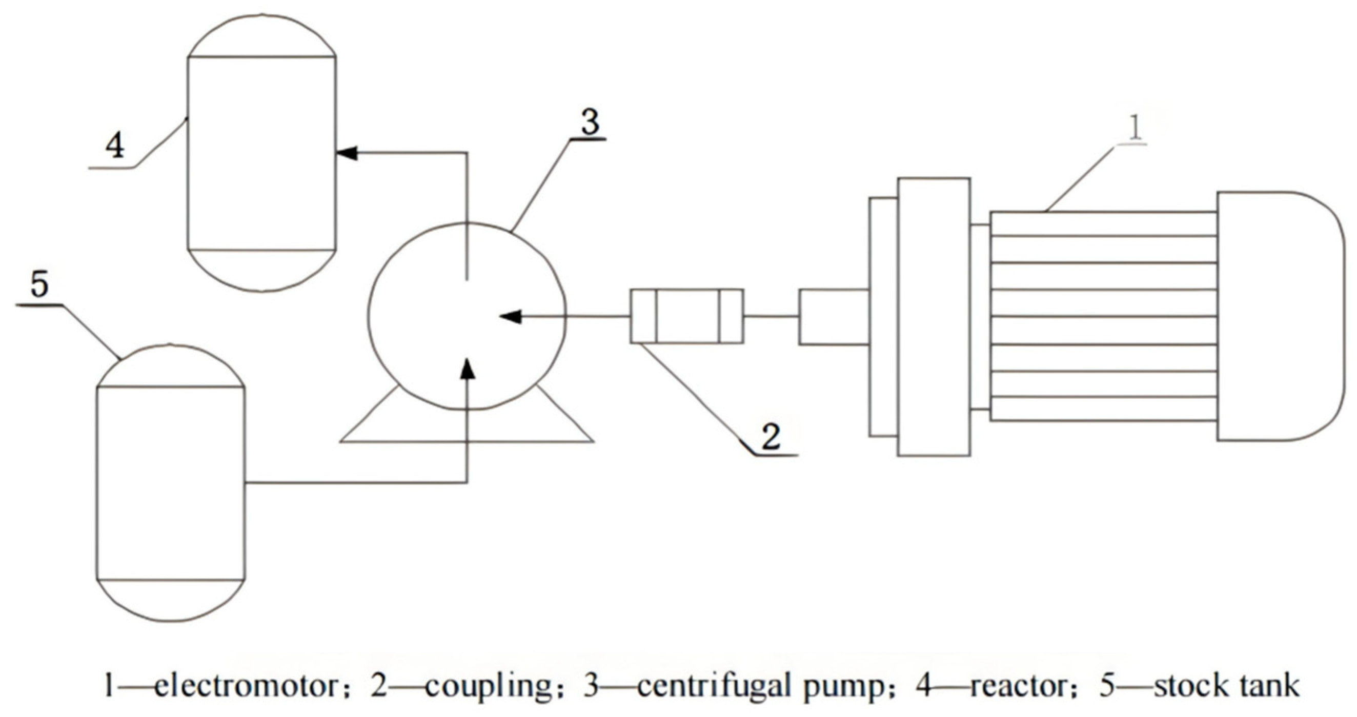
An energy rating system has been developed to improve the efficiency of centrifugal pump operation. A centrifugal pump is a kind of mechanical equipment used to convert electric energy into potential and kinetic energies, which is applied to fluids [11]. A schematic diagram of its structure is shown in the following Figure 2.

3.1. Centrifugal Pump Energy Level Formula

The operational state of a pump can be determined by utilizing existing measurements of key parameters and applying a mathematical model to assess performance and detect anomalies [12,13]. In the study of Ref. [14], the authors pointed out that a general model with adjustable parameters could be used to estimate the operating state of the pump. Therefore, this paper primarily relies on the characteristic curves of centrifugal pumps provided by the manufacturer. The curves are subjected to piecewise polynomial linear fitting, and ultimately, an efficiency model is established on the server. The characteristic curve of a centrifugal pump is obtained by the manufacturer using clear water at 20 °C under normal pressure by changing the opening degree of the valve at the pump outlet. When the system obtains the flow information of the centrifugal pump through the intelligent differential pressure transmitter, it can automatically calculate the corresponding efficiency and head information. The intelligent differential pressure transmitter type is a suction pressure type; the accuracy is ±0.075%, and the uncertainty is ±0.15% FS. For some pieces of centrifugal pump equipment, whose parameters cannot be fully obtained, but the transport medium is water, the actual time efficiency can be obtained by this method, so as to evaluate the energy efficiency grade of the centrifugal pump operation [15,16,17].
The energy efficiency grade evaluation of the centrifugal pump allows for a quick and intuitive understanding of the current equipment’s operation, enabling on-site equipment management personnel to replace or upgrade the equipment as needed. According to the Chinese national standard [18], the energy efficiency grade of a centrifugal pump can be categorized into three levels: the first level (η1), the second level (η2), and the third level (η3), with the first level being the highest and the third level being the lowest.
The logical calculation process for energy level evaluations is as follows:
(1)
The equation for calculating the specific rotational speed of the centrifugal pump is shown below:
n s = n × 3.65 × Q / 3600 H 3 / 4
(2)
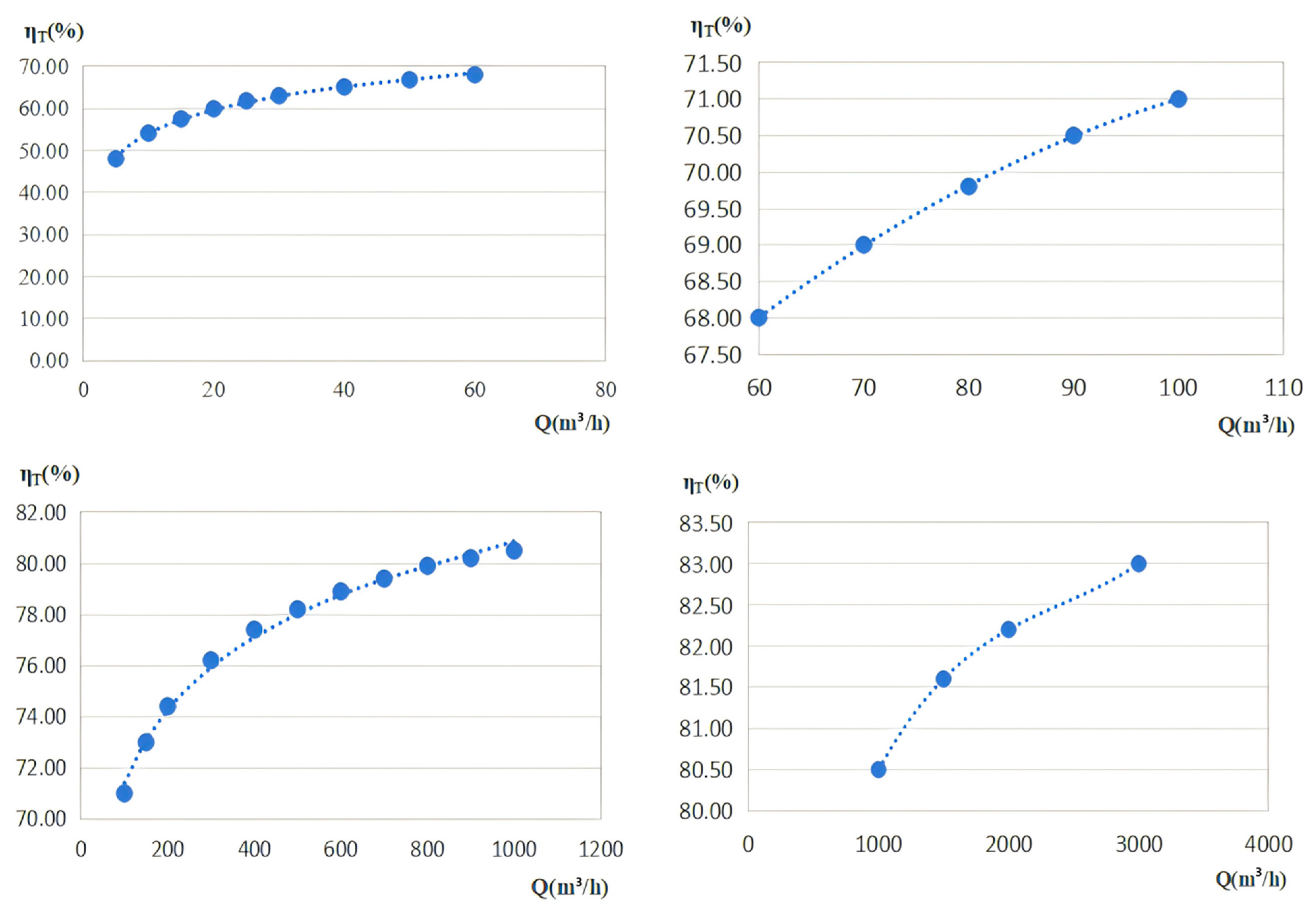
According to the value provided by the manufacturer, the flow rate (Q) and efficiency reference value (η) can be obtained, as shown in Figure 3. In order to prevent overfitting [19], we limit the highest degree of the fitted polynomial to 0 to 3. The segment function of the reference efficiency (η) is shown in Equation (2):
η = 8.0372 lnQ + 37.524 , 5 Q < 60 0.0008 Q 2 + 0.2007 Q + 60.789 60 Q < 100 4.1065 lnQ + 54.489 100 Q < 1000 4 e 10 Q 3     3 e 0.6 Q 2 + 0.0071 Q + 77.7 1000 Q < 3000
The efficiency value (η) of the centrifugal pump can be determined using the measured flow rate (Q) and the feed function (2).
(3)
Figure 4 is a graph of the flow rate and the target energy efficiency limits. The segment function obtained from this fitting is shown in Equation (3):
η = 8.0372 lnQ + 35.524 , 5 Q < 60 0.0008 Q 2 + 0.2007 Q + 58.789 60 Q < 100 4.11 l   nQ + 54.389 100 Q < 1000 4 e 10 Q 3     3 e 0.6 Q 2 + 0.0071 Q + 75.7 1000 Q < 3000
The target energy efficiency limit value(ηT) of the centrifugal pump can be determined using the measured flow rate (Q) and the feed function (3).
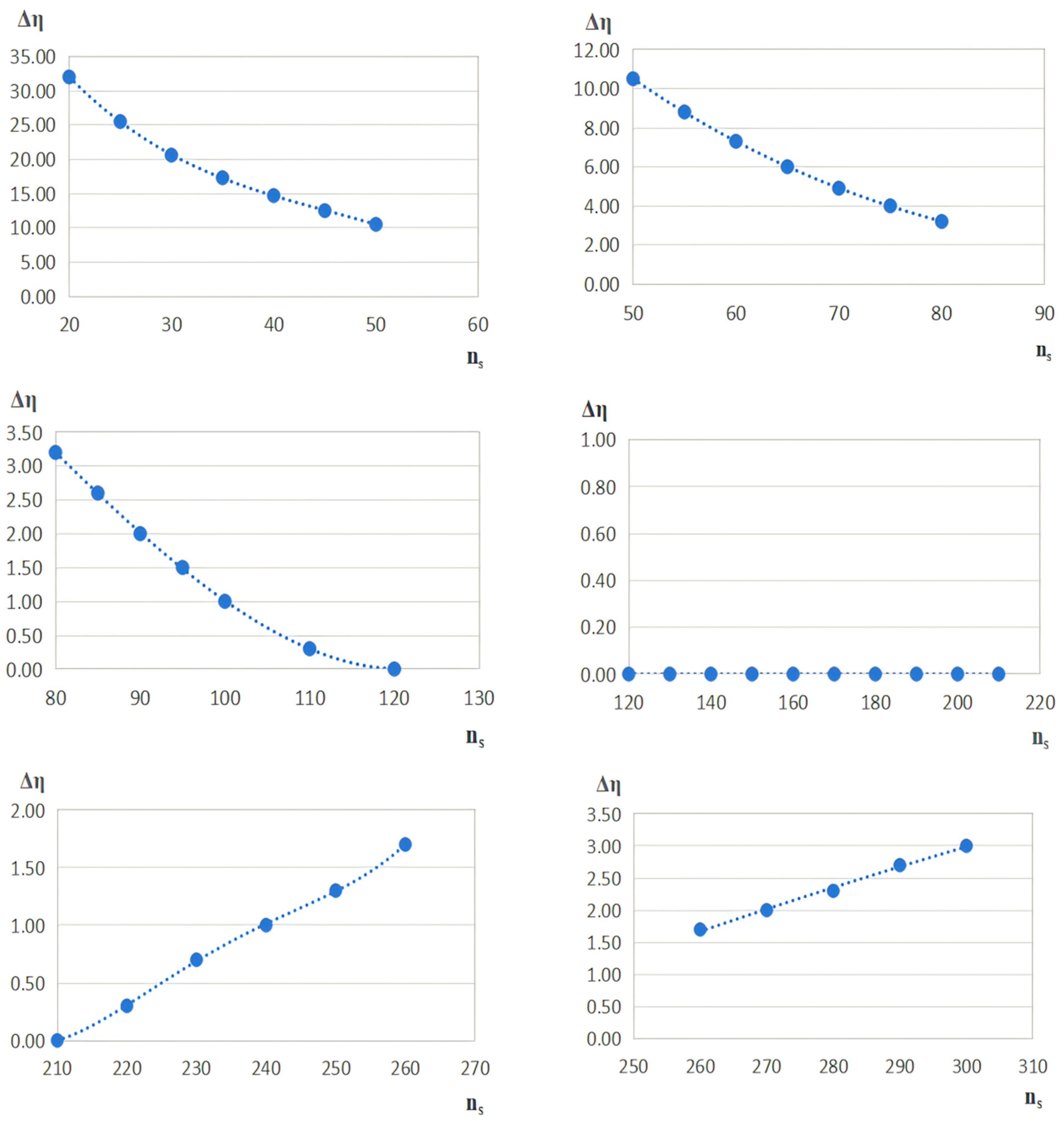
Figure 5 shows the curve diagram of the speed ratio of a centrifugal pump and the efficiency correction value. The segment function obtained from this fitting is shown in (4):
η = 0.00058 n s 3 + 0.0785 n s 2 3.9575 n s + 84.383 , 20 n s < 50 2.2 e 5 n s 3 + 0.0081 n s 2 1.009 n s + 43.493 , 50 n s < 80 1.9 e 5 n s 3 + 0.0043 n s 2 0.1984 n s + 5.1807 , 80 n s < 120 0 120 n s < 210 6 e 7 n s 4 6 e 4 n s 3 + 0.2047 n s 2 31.761 n s + 1804.9 210 n s < 260 9.2174 ln ( n s )     49.586 , 260 n s < 300
The centrifugal pump speed ratio (ns) of the centrifugal pump is calculated as the measured flow Q in Formula (1). The efficiency correction value (Δη) can be obtained by the speed ratio (ns) of the feed function (4).
(4)
Table 1 is the energy efficiency grade evaluation table [20]. According to the real-time flow Q, specific speed ns, efficiency reference value η, target energy efficiency limit value ηT, and efficiency correction value Δη, the first level energy efficiency, second level energy efficiency, and third level energy efficiency of the centrifugal pump are determined.
(5)
The system evaluates the energy efficiency grade of the centrifugal pump according to the fitting results and the actual efficiency of the centrifugal pump ηP:
ηP ≥ η1, the system output of the centrifugal pump for the first level of energy efficiency.
η1 > ηP ≥ η2, the system output of the centrifugal pump for the second level of the energy efficiency.
η2 > ηP ≥ η3, the system output of the centrifugal pump for the third level of energy efficiency.
η3 ≥ ηP, the system outputs that the energy efficiency of the centrifugal pump is lower than the target energy efficiency limit value, and the corresponding energy saving and efficiency increase method is given.

3.2. Three-Phase Asynchronous Electromotor Energy Level Standard

The energy level evaluation of the three-phase asynchronous electromotor is determined by the rated voltage (Ue), the rated power (Ne), the number of motor poles, and the real-time efficiency (ηm) of the motor. According to the rated voltage and rated power, the energy level evaluation of a three-phase synchronous motor is mainly divided into the following two categories:
Category 1: General-purpose motors or general-use explosion-proof motors with a rated voltage (Ue) of less than 1000 V and rated power ranging from 120 KW to 1000 KW (120 KW ≤ Ne ≤ 1000 KW).
Category 2: High-voltage motors with a rated voltage (Ue) of 6000 V and rated power ranging from 185 KW to 2500 KW (185 KW ≤ Ne ≤ 2500 KW).
According to the relevant Chinese national standard [19], the level evaluation standard of the three-phase synchronous motor, whose rated power ranges from 75 KW to 160 KW, is shown in Table 2. By fitting the energy efficiency levels—the first level (η1), second level (η2), and third level (η3)—for two-pole, four-pole, six-pole, and eight-pole motors, respectively, a functional relationship between the motor’s rated power and the energy level evaluation efficiency can be established. By combining the actual efficiency (ηm) of the motor, its energy efficiency grade can be evaluated.
The system evaluates the energy efficiency grade of the motor according to the fitting results and the actual efficiency of the motor:
ηm ≥ η1, the system classifies the motor as having first-level energy efficiency.
η1 > ηm ≥ η2, the system classifies the motor as having second-level energy efficiency.
η2 > ηm ≥ η3, the system classifies the motor as having third-level energy efficiency.
η3 ≥ ηm, the system indicates that the motor’s energy efficiency is below the target limit value and suggests corresponding energy-saving and efficiency-improvement methods.
When ηm and ηp are approximately η1 or η2, the system will classify directly by actual values, which may lead to misjudgment or fluctuations. Therefore, a method of multiple sampling averages will be added to the system to reduce errors.

4. Browser/Server-Based System Development

4.1. System Development Architecture

B/S (Browser/Server) architecture refers to a system development architecture mode where the client directly connects to the server, which is widely used in the development of network application systems [21]. B/S architecture offers simple maintenance, broad applicability, strong portability, low usage costs, and a relatively relaxed network hardware environment. The rational use of B/S architecture can not only reduce the operation requirements of the client, but can also make the system’s development and application simpler and lighter, providing convenience for system maintenance [22,23]. In this system, all functional services are deployed on the server side, while the browser client requires minimal logic processing to achieve the required functionalities. This development approach, which eliminates the need for additional client-side software installation, significantly simplifies system maintenance and upgrade processes. By leveraging the SpringBoot framework and the B/S architecture’s automated configuration and rapid startup capabilities, a robust and efficient runtime environment has been established for data storage, processing, and forwarding.
SpringBoot is an open-source framework developed by the Pivotal team to simplify Spring applications. It represents an upgrade and extension of Spring technology [24]. In the system development, the personalized configuration and optimization of the SpringBoot framework not only ensures the rapid development of the system, but also ensures the high efficiency of the system operation and the clear development hierarchy [25]. The system has achieved an effective balance between design, development, and practical application, generally presenting satisfactory performance metrics and application value.
The core startup code for SpringBoot is as follows:
@SpringBootApplication
@EnableTransactionManagement
@EnableCaching
@ServletComponentScan
@MapperScan(“com.allen.energy.mapper”)
public class EnergyApplication {
public static void main(String[] args) {
SpringApplication.run(EnergyApplication.class, args);}}
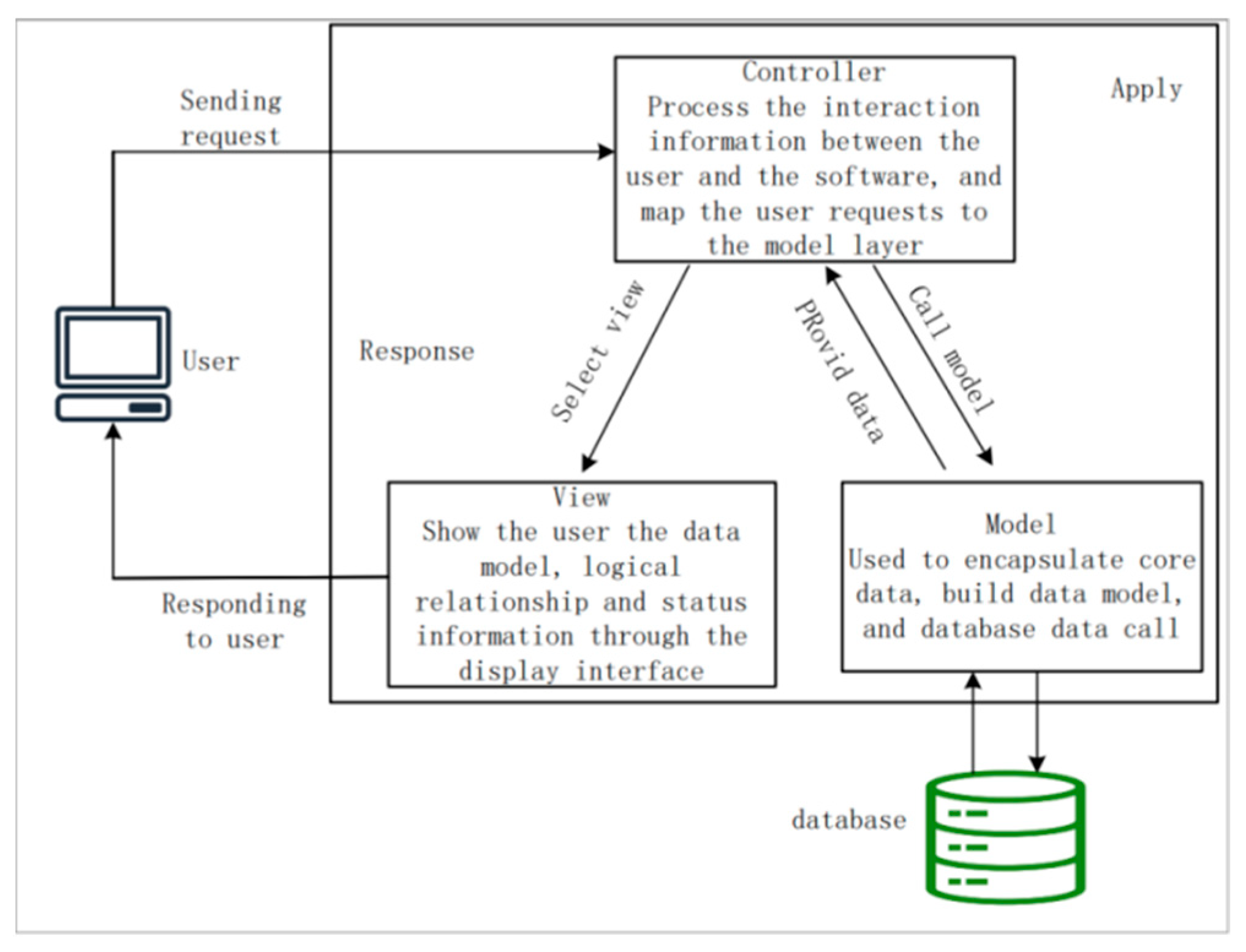
MVC (Model–View–Controller) architecture [26] is one of the mainstream design modes for the Web development, which involves separating the system’s front-end interface, data processing, and business logic into distinct layers; this way, you can modify a more complex system into simple structures and logical parts to enhance the code’s and program’s scalability, maintenance, and robustness. The schematic diagram of its design mode is shown in Figure 6.

4.2. System Front-End Design

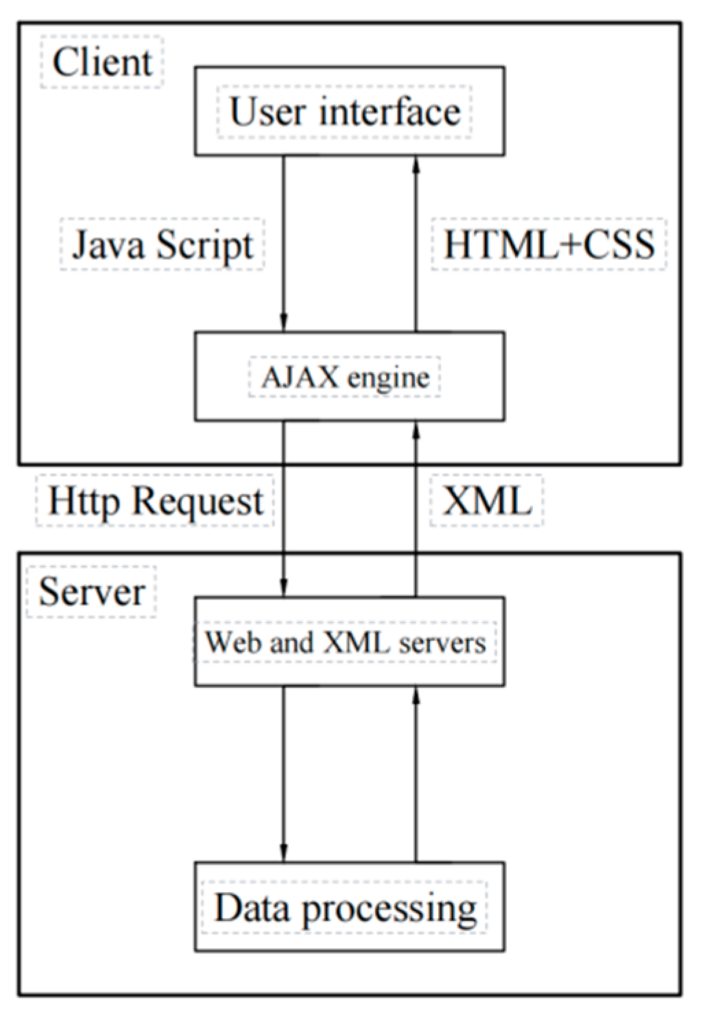
The design of the system’s front-end page primarily utilizes HTML, CSS, JavaScript, ECharts, and Ajax technologies to construct a comprehensive front-end display interface, enabling the graphical display and dynamic updating of real-time data. Ajax, which stands for ‘Asynchronous JavaScript and XML,’ adds an Ajax engine between the user and the server, enabling user operations to synchronize with server responses [27]. This technology allows users’ requests to communicate with the server through the Ajax engine, making Web applications as powerful as desktop applications. In a Web interface environment, interface elements will make immediate layout changes in response to user behavior, and the browser interface content will be refreshed and adjusted in real time. The Ajax interaction mode is shown in Figure 7.

4.3. Database Technology

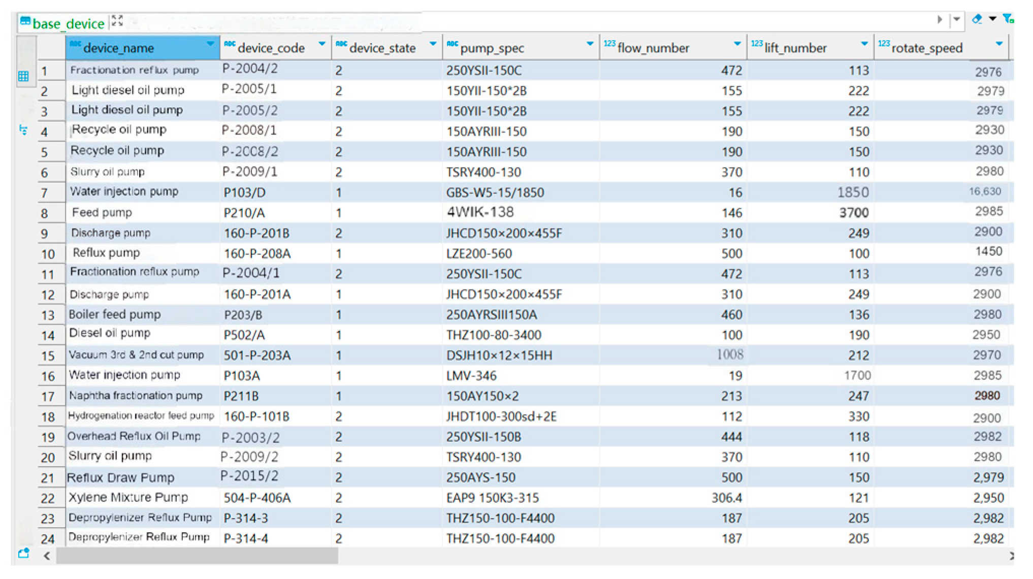
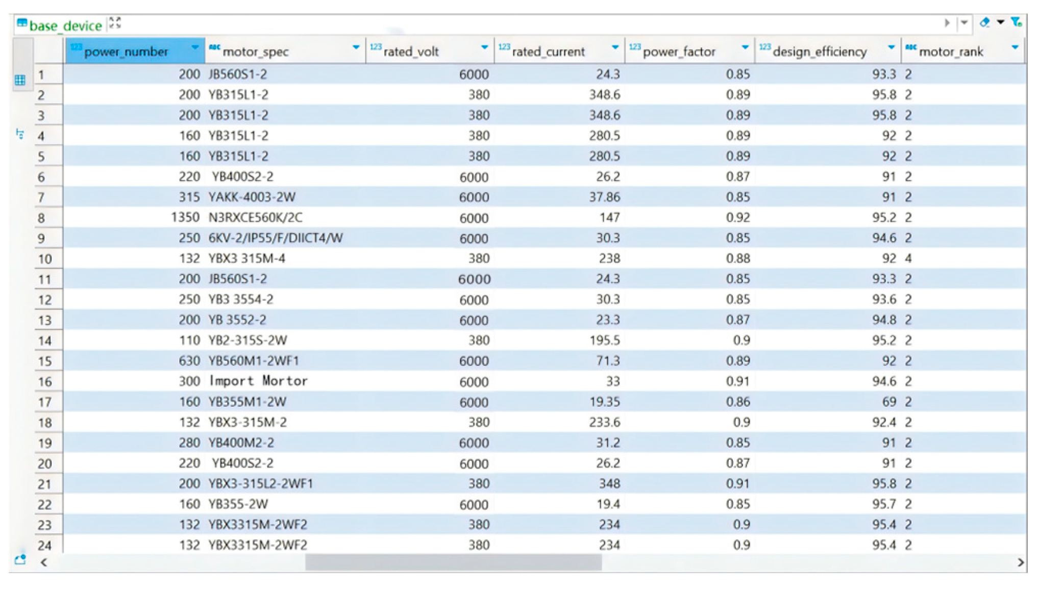
To complete the online evaluation of the energy efficiency grade of the centrifugal pump unit, the system needs to store performance data sheets for centrifugal pumps, motors, and user information. The system development fully utilizes PostgreSQL’s built-in advanced indexing functions and parallel computing processing mechanism in PostgreSQL to ensure the efficiency and accuracy of data processing [28]. At the same time, it also integrates MyBatis tools to achieve rapid responses to large volumes of data, ensuring the stability and reliability of system operations [29]. In addition, in view of the large number of centrifugal pump units required by the system and the complex related data, the basic information, measured parameters, efficiency, and energy efficiency evaluation results for the centrifugal pump units are stored using double precision (double), variable-length character (varchar), and timestamp types, respectively. A role-based permission control strategy is also implemented in the database design process to ensure data security.
Some information from the centrifugal pump performance data table is shown in Figure 8. The partial information in the motor performance data sheet is shown in Figure 9.

4.4. RESTful API Data Interface Technology

RESTful API standardizes various forms of interaction between the front-end and a common back-end using a set of traditional protocols, serving at the core [30]. Each resource has a specific URL for clear access, and the client sends HTTP requests via the URL to perform operations such as acquiring (GET), submitting (POST), updating (PUT), and deleting (DELETE) Web resources.
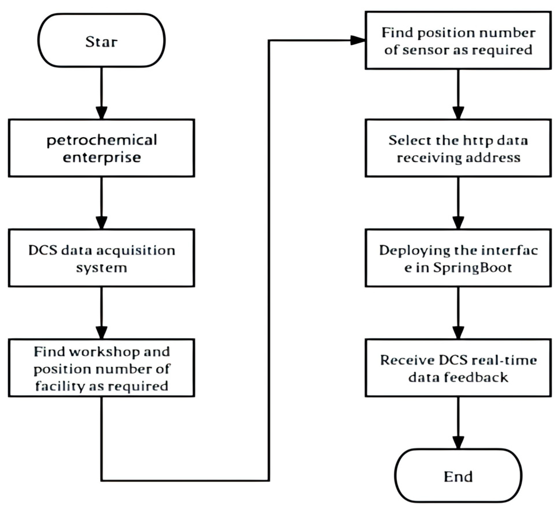
During system development, RESTful API technology not only facilitates real-time data exchange between the front- and back-ends of the system, but also enables the online reading of monitoring data from the DCS systems in petrochemical enterprises. To enable online monitoring of the operating parameters of the centrifugal pump group, the developed system uses the GET method of the RESTful API to read DCS system data in real time. The process of online data acquisition based on RESTful API technology is shown in Figure 10.

5. Main Functional Test of the System

5.1. Basic Parameters of the Centrifugal Pump Unit

The hydrogenation feed pump, with the position number 506-P-101A (Shenyang Industrial Pump Manufacturing Co., LTD., Shenyang, China) in the Hydrocracking unit of a petrochemical enterprise’s refining department, was randomly selected as an example to test the system’s online energy efficiency grade evaluation and other basic functions. The selected centrifugal pump model, GSG100-300/4S, is a four-pole, single-suction pump responsible for transmitting aviation kerosene, with a medium density of 780 kg/m3. The rated parameters are shown in Table 3. The 506-P-101A centrifugal pump is equipped with a YB 355-2W high-voltage power factor of 0.84. The rated parameters are shown in Table 4.

5.2. Implementation of the Equipment Monitoring Function

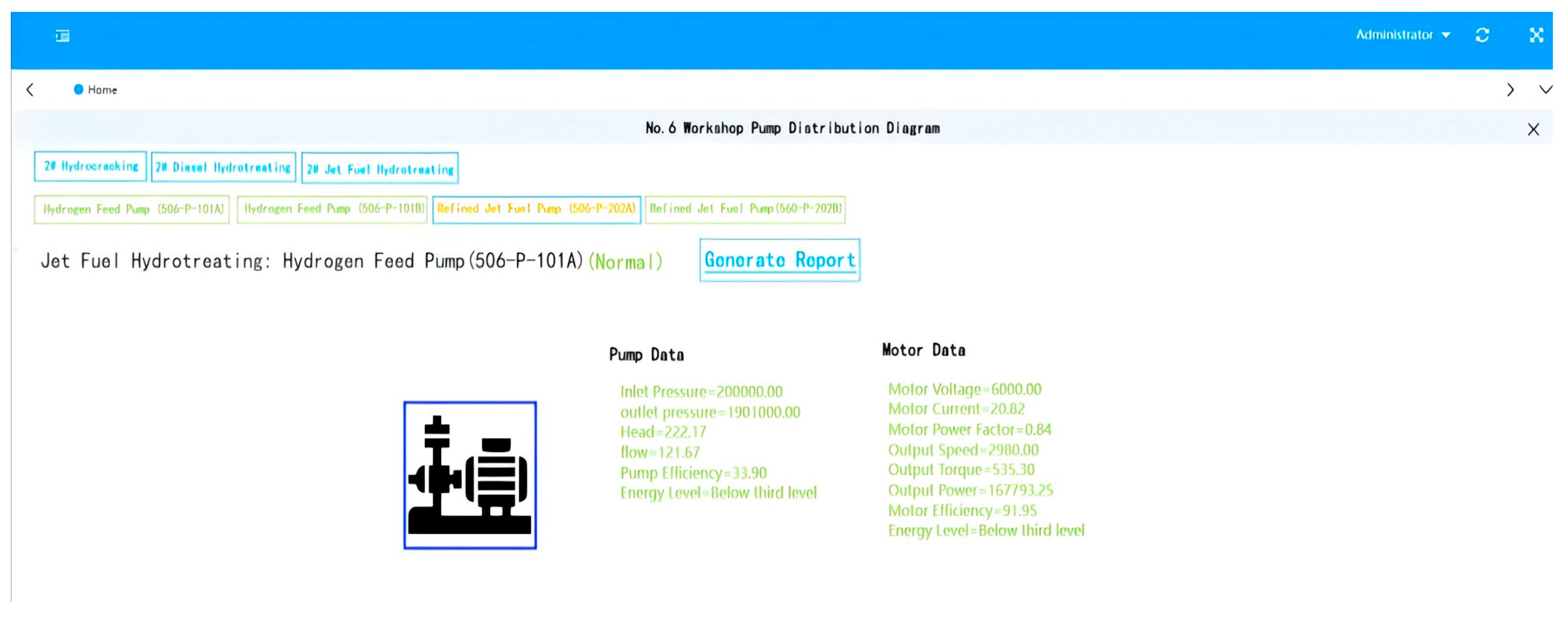
The equipment monitoring interface primarily manages and displays real-time operating parameters of the centrifugal pump and motor, which are monitored in real time by wireless sensors on the equipment, transmitted to the DCS system, and then conveyed to the equipment monitoring interface via the petrochemical enterprise’s internal network. The real-time operation parameters of the centrifugal pump unit are displayed in the “Pump acquisition data” and the “Motor acquisition data” function box. Each parameter is acquired at five-minute intervals, and the data in the function box is automatically refreshed accordingly.
During the system’s operation and testing, the basic parameters of the centrifugal pump unit 506-P-101A and the DCS data interface information are input into the system. On the system’s homepage, the system provides real-time monitoring data for the centrifugal pump unit based on the DCS interface information maintained by the user. The real-time monitoring interface of the centrifugal pump unit data with the position number of 506-P-101A is shown in Figure 11.
The core code of the device monitoring function is as follows:
function getIotData() {
$.getJSON(getRealUrl(“/pump/deptPumpData.do?deviceId=“ + showDeviceId),
res => {$(‘#pump’).//Monitoring of centrifugal pump operating parameters
HTML(`Entrance pressure = ${formatData(res.data.importPressure)}<br />
Outlet pressure = ${formatData(res.data.exportPressure)}<br />
Head of delivery = ${formatData(res.data.liftNumber)}<br />
Flow = ${formatData(res.data.flowNumber)}<br />
Efficiency of pump = ${formatData(res.data.resEnergy)}<br />
Energy level = ${formatData(res.data.energyLevel)}`);
$(‘#moto’).//Motor operation parameter monitoring
HTML(`Motor voltage = ${formatData(res.data.motorVolt)}<br />
Motor current = ${formatData(res.data.motorCurrent)}<br />
Motor power factor = ${formatData(res.data.motorPowerFactor)}<br />
Output speed = ${formatData(res.data.outSpeed)}<br />
Output torque = ${formatData(res.data.outRect)}<br />
Output power = ${formatData(res.data.outPower)}<br />
Electric efficiency = ${formatData(res.data.motorEnergy)}`);}

5.3. Realization of the Online Evaluation Function of Energy Efficiency Grade

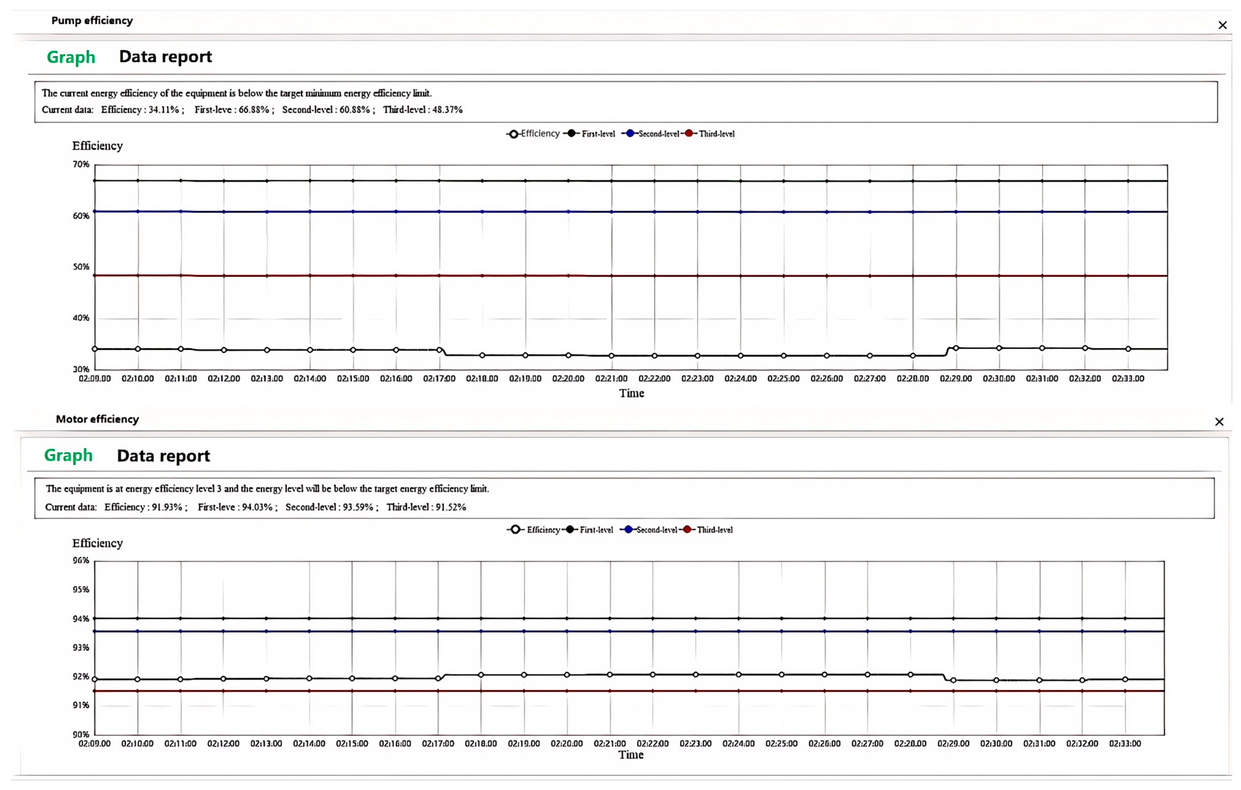
Clicking on the ‘Pump Acquisition Data’ or ‘Motor Acquisition Data’ function box in the equipment monitoring diagram automatically directs the user to the energy efficiency grade evaluation curve interface. In the energy efficiency evaluation interface, black lines indicate the efficiency of the centrifugal pump unit, and green, blue, and red lines, respectively, indicate the energy efficiency of the centrifugal pump unit’s first level, second level, and third level in the characteristic time. The interface records the parameters of the centrifugal pump unit collected each time and automatically generates them into a curve. By cross-comparing the real-time efficiency and energy efficiency grade evaluation standard curve, the energy level of the centrifugal pump unit can be determined within a certain period of time, and the evaluation is given. In addition, users can move the cursor in the energy efficiency rating curve interface to understand the efficiency of the centrifugal pump or motor at a certain time. Clicking the left mouse button also allows viewing the energy efficiency rating and efficiency values at a specific point in time.
The evaluation results of the centrifugal pump with the position number 506-P-101A and the corresponding motor’s energy efficiency grade evaluation results are shown in Figure 12.
Therefore, the system represented by 506-P-101A has been tested on the centrifugal pump. The measured results show that the interface response is smooth, and the data update is timely. Users can intuitively see the running status of the equipment according to the interface shown in the figure above. The system is usable and suitable for industrial field deployment.

6. Conclusions

In this study, we successfully developed an online evaluation system for the energy efficiency grade of centrifugal pump units based on the B/S architecture. By combining real-time monitoring data with direct calculations and characteristic curve fitting, the system can accurately assess the energy efficiency grade of centrifugal pumps. The system uses the B/S architecture and the SpringBoot (2.7.9) framework to achieve efficient development and stable operation. This architecture not only reduces the operational requirements for the client side but also enhances the system’s maintainability and scalability. Additionally, by integrating the characteristic curves provided by manufacturers, a segmented polynomial linear fitting is used to establish an efficiency model, enabling the real-time evaluation of the energy efficiency grade of centrifugal pumps. This method is particularly suitable for centrifugal pump equipment, where all parameters cannot be fully obtained, but the conveyed medium is water.
In terms of system development, we utilized Ajax technology to enable an asynchronous data interaction between the front-end and server, which has improved the system’s response speed and user experience. Users can now view the operating parameters and energy efficiency levels of centrifugal pumps in real time through the system. We implemented efficient data processing using PostgreSQL (V.15.2) and MyBatis. Additionally, the system features role-based permission control to ensure data security.
There are still shortcomings in the system: The system is currently browser-centric, requiring occasional browser-specific tweaks and manual data maintenance. Leveraging existing DCS infrastructure, the study targets the B/S evaluation layer and intentionally leaves sensor hardware and fieldbus design to future work.
Tests on 483 centrifugal pumps at a petrochemical company demonstrated that the system exhibits high stability and accuracy, significantly reducing evaluation time and enhancing energy efficiency. Practical applications have validated the system’s effectiveness and practicality, providing a simple yet precise evaluation system for companies and laying a solid theoretical and practical foundation for their digital transformation.

Author Contributions

Software, J.L. (Jingming Liu), Q.H. and J.L. (Jie Liu); Data curation, Y.L.; Writing—original draft, S.G.; Writing—review and editing, M.Z. and T.S. All authors have read and agreed to the published version of the manuscript.

Funding

The scientific research and development project of Sinopec Group Corporation: “Research on Dynamic Energy Efficiency Evaluation and Improvement Technology Application for Pump Groups” (Grant Number: TFBC230040).

Data Availability Statement

The original contributions presented in this study are included in the article. Further inquiries can be directed to the corresponding author(s).

Conflicts of Interest

Jingming Liu, Qiang Huang and Yang Liu were employed by the Sinopec Tianjin Petrochemical Co., Ltd. The remaining authors declare that the research was conducted in the absence of any commercial or financial relationships that could be construed as a potential conflict of interest. The Sinopec Tianjin Petrochemical Co., Ltd. company had no role in the design of the study; in the collection, analyses, or interpretation of data; in the writing of the manuscript, or in the decision to publish the results.

References

  1. De Almeida, A.; Fong, J.; Brunner, C.U.; Werle, R.; Van Werkhoven, M. New technology trends and policy needs in energy efficient motor systems-A major opportunity for energy and carbon savings. Renew. Sustain. Energy Rev. 2019, 115, 109384. [Google Scholar] [CrossRef]
  2. Miao, C.; Fang, D.; Sun, L.; Luo, Q. Natural resources utilization efficiency under the influence of green technological innovation. Resour. Conserv. Recycl. 2017, 126, 153–161. [Google Scholar] [CrossRef]
  3. Zhang, Y.; Jiang, C.; Shou, B.; Zhou, W.; Zhang, Z.; Wang, S.; Bai, B. A quantitative energy efficiency evaluation and grading of plate heat exchangers. Energy 2018, 142, 228–233. [Google Scholar] [CrossRef]
  4. Muralidhar, K.; Rajasekar, N. A review of various components of solar water-pumping system: Configuration, characteristics, and performance. Int. Trans. Electr. Energy Syst. 2021, 31, e13002. [Google Scholar] [CrossRef]
  5. Vikhlyantsev, A.A.; Volkov, A.V.; Ryzhenkov, A.V.; Druzhinin, A.A.; Šoukal, J.; Sedlař, M.; Komárek, M.; Pochylý, F.; Rudolf, P.; Fialová, S. Increasing Efficiency for MicroHPP Hydroturbines Operating under Variable Head Pressure Using an Aperiodic Blade System. Therm. Eng. 2020, 67, 922–930. [Google Scholar] [CrossRef]
  6. Emami, S.A.; Emami, M.H. Design and Implementation of an Online Precise Monitoring and Performance Analysis System for Centrifugal Pumps. IEEE Trans. Ind. Electron. 2018, 65, 1636–1644. [Google Scholar] [CrossRef]
  7. Chen, L.; Wei, L.; Wang, Y.; Wang, J.; Li, W. Monitoring and Predictive Maintenance of Centrifugal Pumps Based on Smart Sensors. Sensors 2022, 22, 2106. [Google Scholar] [CrossRef]
  8. Zhang, M. Research on Flowrate Control and Lifecycle Prediction Method of Centrifugal Pump Based on Condition Monitoring System. Master’s Thesis, Jiangsu University, Zhenjiang, China, 2022. [Google Scholar]
  9. Feng, F.; Cai, D.; Chang, Z.; Wu, J.; Bamisile, O.; Huang, Q. Exploring the Performance Test of Smart Substation Auxiliary Control System Test Platform Based on B/S Architecture. In Proceedings of the International Conference on Power and Electrical Engineering, Singapore, 3–5 November 2023; Springer Nature Singapore: Singapore, 2023; pp. 175–185. [Google Scholar]
  10. Li, D. Green Logistics Supply Chain System Based on B/S Architecture and Mileage Saving Algorithm. Sustain. Oper. Comput. 2025, in press. [Google Scholar] [CrossRef]
  11. Zhao, Y. Research on energy evaluation system of transfer pump unit based on combination model. Energy Conserv. Meas. Pet. Petrochem. Ind. 2023, 13, 61–65. [Google Scholar]
  12. Hammo, S.; Viholainen, J. Testing the accuracy of pump flow calculation without metering. World Pumps 2005, 2005, 36–39. [Google Scholar] [CrossRef]
  13. Frequency-converter-based hybrid estimation method for the centrifugal pump operational state. IEEE Trans. Ind. Electron. 2011, 59, 4803–4809.
  14. Ahonen, T.; Tamminen, J.; Ahola, J.; Viholainen, J.; Aranto, N.; Kestilä, J. Estimation of pump operational state with model-based methods. Energy Convers. Manag. 2010, 51, 1319–1325. [Google Scholar] [CrossRef]
  15. Heo, M.W.; Ma, S.B.; Shim, H.S.; Kim, K.Y. High-efficiency design optimization of a centrifugal pump. J. Mech. Sci. Technol. 2016, 30, 3917–3927. [Google Scholar] [CrossRef]
  16. Hieninger, T.; Schmidt-Vollus, R.; Schlücker, E. Improving energy efficiency of individual centrifugal pump systems using model-free and on-line optimization methods. Appl. Energy 2021, 304, 117311. [Google Scholar] [CrossRef]
  17. Bordeasu, D.; Dragan, F.; Filip, I.; Szeidert, I.; Tirian, G.O. Estimation of Centrifugal Pump Efficiency at Variable Frequency for Irrigation Systems. Sustainability 2024, 16, 4134. [Google Scholar] [CrossRef]
  18. GB 32284-2015; Minimum Allowable Values of Energy Efficiency and Energy Efficiency Grades for Petrochemical Centrifugal Pumps. General Administration of Quality Supervision, Inspection and Quarantine of the People’s Republic of China; Standardization Administration of the People’s Republic of China: Beijing, China, 2015.
  19. Khan, A.; Bradshaw, C.R.; Schmitt, J.; Langebach, R. Predicting vapor injected compressor performance using artificial neural networks. In Proceedings of the International Compressor Engineering Conference, West Lafayette, IN, USA, 15–18 July 2024. [Google Scholar]
  20. GB 30254-2013; Minimum Allowable Values of Energy Efficiency and the Energy Efficiency Grades for Cage Three-Phase High Voltage Induction Motor. Standardization Administration of the People’s Republic of China; General Administration of Quality Supervision, Inspection and Quarantine of the People’s Republic of China: Beijing, China, 2013.
  21. Liu, J.P.; Cai, S.Q.; Liu, S.Y.; Ren, X.L.; Xie, Z.P. Visual management method and system for station assets. Softw. Guide 2024, 1–10. Available online: https://kns.cnki.net/kcms2/article/abstract?v=9oehDy4zW5b75J_-QaNlTdCq-yAo9yQZyVJwLFAigIoiPzbHNUuq4dddFIpV-zdT9qYdgXpO2wfv-nmqGeVR6CNyiD2eU9qf4hMI5r25tezCCpAdReO2oGHjfdMBWj9eRF5Y2NsYymfNlryetrrdPtCbIHM7-G5G4cJxvi1cWfVLH0PdcIwHnL9UrLKJHUpghiOqLGsx9lE=&uniplatform=NZKPT (accessed on 15 August 2025).
  22. Jain, P.; Munjal, Y.; Gera, J.; Gupta, P. Performance analysis of various server hosting techniques. Procedia Comput. Sci. 2020, 173, 70–77. [Google Scholar] [CrossRef]
  23. Nyabuto, M.G.M.; Mony, V.; Mbugua, S. Architectural review of client-server models. Int. J. Sci. Res. Eng. Trends 2024, 10, 139–143. [Google Scholar] [CrossRef]
  24. Hu, P.F.; Yu, Q. Remote-control system of space station high temperature cabinet foundation experiment based on B/S architecture. Comput. Appl. Softw. 2023, 40, 9–15+78. [Google Scholar]
  25. Jani, Y. Spring boot for microservices: Patterns, challenges, and best practices. Eur. J. Adv. Eng. Technol. 2020, 7, 73–78. [Google Scholar]
  26. Subari, A.; Manan, S.; Ariyanto, E. Implementation of MVC (Model-View-Controller) architecture in online submission and reporting process at official travel warrant information system based on web application. J. Phys. Conf. Ser. 2021, 1918, 042145. [Google Scholar] [CrossRef]
  27. Song, J.H.; Cao, Y. The Design and Implementation of ASP.NET AJAX Technology Based Online Test System. Comput. Knowl. Technol. 2009, 5, 7161–7163. [Google Scholar]
  28. Qin, W.R. Construction and Application Multi-Source Geographic Information Map Supporting Compound Condition Query. Master’s thesis, Beijing University of Posts and Telecommunications, Beijing, China, 2022. [Google Scholar]
  29. Jiang, C.; Bao, Z.; Li, C. A Brief Analysis of the Application of MyBatis in Java Development. J. Theory Pract. Eng. Technol. 2024, 1, 25–32. [Google Scholar]
  30. Wang, R. Web-Based Chinese Musical Instrument Digital Museum System. Master’s thesis, Huazhong University of Science and Technology, Wuhan, China, 2018. [Google Scholar]
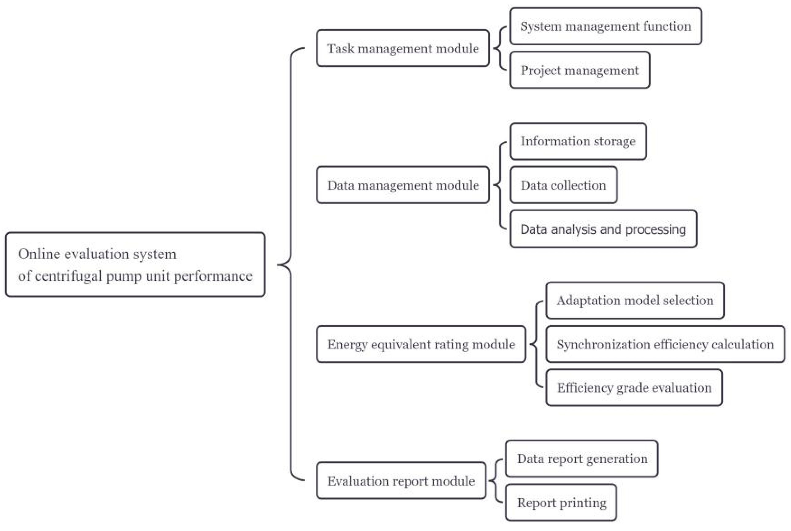
Figure 1. The overall framework of the energy efficiency rating system for centrifugal pump units.
Processes 13 02650 g001
Figure 2. Schematic diagram of centrifugal pump unit.
Processes 13 02650 g002
Figure 3. Fitting curve for the flow rate and efficiency reference values.
Processes 13 02650 g003
Figure 4. Fitting curve of flow rate and target energy efficiency limits.
Processes 13 02650 g004
Figure 5. Fitting curve of speed ratio of centrifugal pump and efficiency correction value.
Processes 13 02650 g005
Figure 6. MVC design pattern schematic.
Processes 13 02650 g006
Figure 7. Ajax interaction mode.
Processes 13 02650 g007
Figure 8. Centrifugal pump data entry information.
Processes 13 02650 g008
Figure 9. Motor data entry information.
Processes 13 02650 g009
Figure 10. Online data collection process based on RESTful API technology.
Processes 13 02650 g010
Figure 11. 506-P-101A data real-time monitoring interface.
Processes 13 02650 g011
Figure 12. Centrifugal pump and motor energy level evaluation curve.
Processes 13 02650 g012
Table 1. Energy level evaluation.
Flow Q (m2/h)Specific Speed (ns)First Level η1(%)Second Level η2(%)Third Level η3(%)
5 ≤ Q ≤ 30020 ≤ ns < 60η − Δη + 10η − Δη + 5ηT − Δη
5 ≤ Q ≤ 30060 ≤ ns < 120η − Δη + 4η − Δη + 1ηT − Δη
5 ≤ Q ≤ 300120 ≤ ns < 210η + 3η − Δη + 1ηT
5 ≤ Q ≤ 300210 ≤ ns < 300η − Δη + 3η − Δη + 5ηT − Δη
Q > 30020 ≤ ns < 60η − Δη + 11η − Δη + 1ηT − Δη
Q > 30060 ≤ ns < 120η − Δη + 5η − Δη + 1ηT − Δη
Q > 300120 ≤ ns < 210η + 3η − Δη + 2ηT
Q > 300210 ≤ ns < 300η − Δη + 3η − Δη + 2ηT − Δη
Table 2. Evaluation of Class II motor energy levels.
Rated Power (KW)First Level η1 (%)Second Level η2 (%)Third Level η3 (%)
Motor Pole Number246824682468
71096.095.996.095.995.195.095.295.094.194.094.294.0
80096.196.196.196.095.395.395.495.294.394.394.494.2
90096.396.296.396.195.595.495.595.394.594.494.594.3
100096.396.396.396.295.595.595.595.494.694.594.694.4
112096.496.396.496.395.695.595.695.594.794.694.794.5
125096.596.496.596.395.895.795.895.694.994.894.994.7
Table 3. Rated parameters of centrifugal pump.
The Parameter NameSymbolUnitNumeric
rated flow Q e m 3 / h 142
rated head H e m388
Designed speed n e r / m i n 2980
Table 4. Rated parameters of three-phase asynchronous motor.
The Parameter NameSymbolUnitNumeric
power rating N e KW200
rated voltage U e V6000
rated current I e A27.2
design efficiency η e %92.30
Disclaimer/Publisher’s Note: The statements, opinions and data contained in all publications are solely those of the individual author(s) and contributor(s) and not of MDPI and/or the editor(s). MDPI and/or the editor(s) disclaim responsibility for any injury to people or property resulting from any ideas, methods, instructions or products referred to in the content.