Abstract
Facing challenges of low efficiency and severe wear in deep hard formations with conventional drilling bits, this study investigates the synergistic rock-breaking technology combining a pulsed CO2 laser with mechanical bits. The background highlights the need for novel methods to enhance drilling speed in high-strength, abrasive strata where traditional bits struggle. The theoretical analysis explores the thermo-mechanical coupling mechanism, where pulsed laser irradiation rapidly heats the rock surface, inducing thermal stress cracks, micro-spallation, and strength reduction through mechanisms like mineral thermal expansion mismatch and pore fluid vaporization. This pre-damage layer facilitates subsequent mechanical fragmentation. The research employs finite element numerical simulations (using COMSOL Multiphysics with an HJC constitutive model and damage evolution criteria) to model the coupled laser–mechanical–rock interaction, capturing temperature fields, stress distribution, crack propagation, and assessing efficiency. The results demonstrate that laser pre-conditioning significantly achieves 90–120% higher penetration rates compared to mechanical-only drilling. The dominant spallation mechanism proves energy-efficient. Conclusions affirm the feasibility and significant potential of CO2 laser-assisted drilling for deep formations, contingent on optimized laser parameters, composite bit design (incorporating laser transmission, multi-head layout, and environmental protection), and addressing challenges, like high in-situ stress and drilling fluid interference through techniques like gas drilling. Future work should focus on high-power laser downhole transmission, adaptive control, and rigorous field validation.
1. Introduction
As oil and gas exploration progresses, reaching deeper and deeper layers of the earth, the composition of the rock formations is becoming increasingly complex. This poses challenges to conventional mechanical drilling bits, which are unable to effectively break up the hard rock formations found in deep drilling operations. These challenges include low efficiency in breaking up the rock, severe wear and tear on the drill bits, and high operating costs. Conventional three-cone bits and PDC (Polycrystalline Diamond CompactBit) bits are applicable to different formations; however, when encountering high hardness and abrasive formations, they often experience problems such as slow progress, chipping, and cutting teeth falling off. Frequent replacement of drill bits can result in an extended drilling cycle and increased expenses. Consequently, the industry must explore new and efficient rock-breaking methods to increase the speed of deep drilling and reduce tool wear [1].
The utilization of high-energy laser drilling technology has garnered significant attention due to its capacity for non-contact rock breaking. Lasers have been demonstrated to remove rock by delivering instantaneously enormous amounts of energy that cause rapid localized heating of the rock, resulting in melting, vaporization, and thermal stress cracking. Research has demonstrated that state-of-the-art lasers can facilitate rock drilling operations at rates that are 10–100 times faster than traditional mechanical methods. Furthermore, laser drilling prevents the drill bit from making contact with the rock, thereby reducing the time required to initiate and cease drilling operations, as well as to change drill bits [2]. However, reliance on lasers for direct rock gasification and melting necessitates the provision of remarkably high energy levels (>20 kJ/cm3 for boreholes with substantial diameter) and can give rise to the formation of a molten, recondensed glass layer within the borehole wall. In contrast, “thermal fracturing” or “thermal spalling” is regarded as the most energy-efficient laser rock-breaking mechanism, with energy requirements of less than 1 kJ/cm3. This process involves the use of laser-induced thermal stresses to break the rock into small fragments before it is melted. However, there are still significant challenges to be addressed, such as the effective removal of high-temperature slag and the mitigation of cracks that are known to form during the process of direct laser rock breaking. Additionally, there is a need to develop methodologies that can interfere with laser transmission within the downhole high-pressure fluid environment.
In light of these developments, a novel concept has emerged in recent years: the integration of laser technology with mechanical rock-breaking methods. This innovative approach, termed “laser-assisted drilling” or “laser-mechanical composite rock breaking,” has shown significant potential in the field. The principle underlying this method is that, in the mechanical drill bit, the introduction of laser pre-exposure to the rock surface, rapid heating to weaken the rock strength, and subsequent mechanical breakage create favorable conditions, thereby significantly improving drilling speed. This composite technology utilizes a laser to actively weaken the rock (e.g., ablation grooves, induced cracks), and then passively breaks the residual rock by the drill bit teeth. The advantages of the two complement each other [3]. Experiments have demonstrated that laser pre-fracturing significantly increases rock drillability. Compared with purely mechanical drilling, the combined rock breaking reduces torque and drilling pressure fluctuations by approximately 20–30%, and more than doubles the drilling speed. Huang et al.’s study shows that the introduction of a laser forms a through thermal damage zone on the rock surface, which significantly reduces the strength of the rock and makes the PDC teeth break the rock with less effort. The drilling speed is increased by 112%. The laser-PDC hybrid bit developed by ForoEnergy in the United States has demonstrated a penetration rate that is 2–3 times that of conventional bits in ultra-hard rock, while requiring drilling pressure that is less than one-tenth of that of the conventional method. It has been demonstrated that laser-mechanical coupling rock breaking has considerable potential in the context of deep hard strata in the comparison of three different drilling methods (Table 1).

Table 1.
Schematic comparison of drilling methods.
This thesis conducts a theoretical and simulation study on the coupled rock-breaking technology of CO2 laser pulses and composite mechanical drills. The CO2 gas laser is selected for its ability to generate high-power infrared laser light and to efficiently heat the rock surface without liquid interference. The initial phase of the study will entail an analysis of the thermo-mechanical response mechanism of rocks under the action of a CO2 laser, encompassing microcrack evolution, phase transformation, and thermal stress distribution. The subsequent discussion will address the structural design elements of the laser-mechanical composite drill bit. Utilizing finite element numerical simulation, the laser-mechanical-rock interaction model will be established. This model will facilitate the simulation of thermal stress fields and crack extension laws. The rock-breaking efficiency and adaptability of this technology will be evaluated. The article concludes with a summary of the key findings, highlighting the technical advantages of CO2 laser-assisted rock breaking, and exploring its potential applications in deep drilling [4].
It is important to acknowledge a current limitation within the scope of this initial phase of the research. Due to constraints in accessing specialized high-power pulsed CO2 laser and integrated laser-mechanical drilling test facilities within our institution, the validation of the developed numerical models and the direct observation of the coupled thermo-mechanical fracture processes described herein are currently pending experimental verification under representative conditions. Collaborative arrangements for conducting these essential physical experiments at an external facility equipped with the necessary capabilities are actively in progress and awaiting scheduling. Consequently, the findings presented in this study are based solely on theoretical analysis and comprehensive finite element simulations. While the model incorporates established material properties and thermo-mechanical principles and is designed to capture the key physical phenomena, empirical validation remains a critical next step. The insights gained from this computational study, however, provide a vital foundation for guiding the design and parameter optimization of the planned future experiments at the collaborative institution.
2. Theoretical Analysis
2.1. Heat-Force Coupling Mechanism of CO2 Laser Action
Upon the application of a high-power CO2 laser to the rock surface, the energy is rapidly absorbed by the surface layer and converted into heat. This initiates a sequence of thermo-mechanical effects. COMSOL Multiphysics 6.3 software is used for numerical simulation. Make basic assumptions in elasticity to ensure the accuracy and rationality of numerical simulations. In the numerical simulation of laser-assisted rock breaking, the type of thermal conduction between the rock and the environment is set as natural convection. When the rock surface is continuously irradiated by a laser, thermal energy is transferred to the surrounding environment and the interior of the rock through thermal conduction. Assuming an initial temperature of 293 K, the heat transfer equation can be expressed as
In the formula: is the density of the material, kg/m3; C is the constant pressure specific heat capacity of the material, J/(kg·K); T is temperature, K; λ is thermal conductivity; and η is the material’s absorption rate of laser energy. First, in the area of laser beam action, the temperature of the rock surface rises instantaneously, and the temperature gradient is extremely steep. To illustrate this phenomenon, consider the case of sandstone, which exhibits significant absorption of the 10.6-micrometer wavelength of the CO2 laser. This results in the rapid heating of the surface layer of quartz-rich rocks, reaching temperatures in the hundreds or even thousands of degrees within a brief period. Concurrently, a lower temperature is maintained at a slightly deeper level. This phenomenon is attributed to thermal expansion of the surface rock, which is constrained by the cooler rock below, leading to the development of high localized stresses within the rock. Compressive stresses occur in the hot zone of the surface layer due to the lower constraints, and tensile stresses occur at the hot-cold interface below it. This set of compressive-tensile stress pairs can easily lead to the initiation and expansion of microcracks in the rock. In the event that the laser pulse power is sufficiently high and the heating rate is rapid, the rock will be unable to warm up uniformly through thermal conductivity [5]. Consequently, the thermal stress will exceed the tensile strength of the rock, thereby producing dense microcracks in the surface layer.
Subsequently, these thermally induced microcracks undergo expansion under stress, resulting in penetration into each other, thereby forming a network of fine fractures (damage zones). In the case of dense rocks, such as granite, it has been observed that laser thermal stresses initially generate microcracks in the surface layer. These microcracks then extend beneath compressive stresses. Subsequently, the cracks flex and continue to propagate forward. Ultimately, the compressive stresses remove a thin slice of the rock from the surface layer, thereby forming “spallation” fragments. This process is referred to as thermal exfoliation. The process is distinguished by its high degree of efficiency, which is attributable to the generation of thermal stresses that cause the rock to fracture prior to melting. The thermal spallation mechanism has been identified as the most energy-efficient method of rock fragmentation using lasers.
Furthermore, the preexisting weak facets and volatile components in the rock are also involved in the rock-breaking process. A significant proportion of stratigraphic rocks are known to contain pore fluids or mineral crystalline water. It has been demonstrated that CO2 laser heating can cause the water in the pores to vaporize and expand instantaneously, resulting in microbursting and intensifying the creation and expansion of cracks within the rock. To illustrate, in the case of porous water-bearing rocks, such as sandstone and shale, the application of laser pulses with a low power density of approximately 104 W/cm2 has been demonstrated to induce the expansion and vaporization of the pore water and cement. This process is facilitated by the generation of heat, leading to the formation of local high pressures [6]. These pressures subsequently exert an outward force on the rock grains, thereby facilitating thermal disintegration and fracture. Tests have demonstrated that in the laser irradiation area, the rock surface will exhibit signs of bulging, cracking, and the expulsion of small rock chips, which are the result of internal water vapor pressure cracking. Consequently, the combined effects of laser action, thermal expansion stress, and phase change expansion stress (e.g., water vaporization) collaborate to expedite the deterioration of the rock [7].
It is worth noting that the surface roughness of rocks significantly affects the energy absorption efficiency of the CO2 laser. Rough surfaces can improve the laser energy coupling rate by enhancing diffuse reflection and multiple internal reflections. Batarseh et al. [8] confirmed through surface control experiments on granite that when the arithmetic mean deviation (Ra) of the surface profile increased from 1.6 μm to 12.5 μm, the laser absorption rate at 10.6 μm increased by 22% to 58%. The mechanism lies in:
- Surface micro protrusions form optical traps, extending the path of photon propagation;
- Multiple reflection enhanced energy deposition within micro cracks;
- The difference in mineral phase transition is amplified, and the local thermal stress is increased by 1.8 times.
In engineering practice, the natural rough surface formed by drill bit cutting (Ra ≈ 3–15 μm) can optimize energy absorption. However, the ultra-high roughness (Ra > 40 μm) caused by rock debris accumulation can trigger laser scattering and reduce effective power density [9]. It is recommended to use optical coherence tomography to monitor surface morphology in real-time and dynamically adjust laser focus and pulse timing.
2.2. Microcrack Evolution and Rock Strength Attenuation
When CO2 laser pulses repeatedly irradiate the rock surface, the thermal cycling effect leads to cumulative microcrack evolution. The rapid heating and cooling cycle of each laser pulse causes the surface rock to undergo repeated loading and unloading of thermal stresses. This is equivalent to loading the rock with “thermal shock fatigue.” The initial microcracks undergo subsequent expansion and interconnection through repeated pulses, resulting in the formation of macroscopically visible cracks and exfoliation pits. Experiments on rock samples demonstrate that following multiple laser scans, the surface of the rock exhibits a reticulated crack structure, the rock debris is flaked off in the form of flakes and fine grains, and the strength of the rock surface layer is significantly reduced. The laser pre-damage effect significantly reduced the compressive and shear strength of the rock. For instance, a study that compared the strength of sandstone before and after laser heating found that laser ablation can reduce its compressive strength by more than 40%, Deng et al. [10] studied the effect of circular laser spot scanning on the strength and drillability of granite and found that under the given parameters, the uniaxial compressive strength of rocks can be reduced by 24%, greatly enhancing its drillability [11].
Microscopically, two primary categories of laser-induced cracks have been identified: thermal stress cracks, which predominantly manifest as tensile cracks extending along intergranular or weak surfaces, and thermal deterioration cracks, which are triggered by the uneven thermal expansion of minerals or phase transition, often originating at the interface of mineral particles. In the case of rocks comprising multiple minerals, such as quartz and feldspar in sandstone, the application of laser heating can generate shear stresses at the mineral interface due to the disparate thermal expansion coefficients of the constituent minerals [12]. This phenomenon leads to interfacial debonding cracks, resulting from the separation of the mineral grains due to the applied stress. These microcracks are interconnected, and the macroscopic strength of the rock is significantly reduced following the formation of a through rupture zone. The impact of the CO2 laser pulse on the rock can thus be regarded as “pre-cracking” the rock internally, with an effect analogous to that of creating a weak damage layer. The subsequent action of a mechanical drill requires only a small amount of stress to break up the damaged layer and strip it away. This is the fundamental reason why laser-assisted mechanical rock breaking can significantly reduce mechanical loads [13].
2.3. Laser-Induced Phase Transition and Material Response
It has been demonstrated that an increase in laser power or action time will result in a phase transition in the rock surface layer, whereby the solid rock undergoes a phase change into a liquid or vaporizes into a plasma. The CO2 laser exhibits high affinity for the Si-O bond, hydroxyl, and water present in the rock, attributable to its wavelength in the far infrared. Consequently, the surface layer of quartz rock can be rapidly heated to its melting point when the power density exceeds 105 W/cm2. For instance, the main component of limestone, CaCO3, undergoes decomposition at approximately 800 °C, releasing CO2 gas. Laser heating has been observed to induce thermal decomposition, leading to the production of gas that facilitates rock disintegration. Continuous laser irradiation will result in the melting of the rock, leading to its partial vaporization into a high-temperature plasma. The high-temperature gases and melts generate shock pressure on the surrounding unheated area, leading to thermal shock wave cracking. Concurrently, the melts undergo cooling, resulting in the formation of a dense slag layer on the rock surface. It is imperative to acknowledge that excessive melting may prove detrimental to the mechanical breaking of the rock, as the recondensed slag has the potential to clog the cracks and increase the hardness of the rock surface. Consequently, the laser parameters must be meticulously regulated to ensure that thermal fragmentation is the primary objective, while extensive melting is actively prevented.
In the context of coupled laser-mechanical rock breaking, the mechanical action can serve to compensate for the absence of slag handling in pure laser rock breaking. The mechanical drill bit effectively removes recondensed melt through scraping, thereby preventing the formation of a glassy, thin layer that might otherwise obscure the rock surface. Consequently, even in cases of localized melting, subsequent mechanical breakage effectively removes the affected area, re-exposing the fresh rock surface to laser action. Consequently, the laser power and the depth of mechanical breakage can be rationally coordinated to avoid the accumulation of molten layers, thereby ensuring that the breakage process can always be carried out in an efficient “thermal cracking-mechanical fragmentation” mode.
2.4. Laser-Mechanical Thermodynamic Coupling Behavior
When the CO2 laser and the mechanical drill bit are synchronized to act on the rock, the rock undergoes thermal–force co-loading, and the damage mode is different from that of either thermal or force loading alone. When exposed to laser irradiation, the thermal stress field generated in the surface layer of the rock is superimposed on the stress field applied by the mechanical drill bit, resulting in a complex stress distribution. To illustrate, the PDC cutting teeth apply localized compressive shear stresses to the rock, while the laser heats the rock in front of the cutting area, thereby decreasing the shear strength and elastic modulus of the area. The application of laser preheating also generates a certain degree of thermal expansion pre-stress at the rock face, which is analogous to pre-cracking the rock. Consequently, the rock exhibits an increased propensity for shear or tensile damage when the drill teeth penetrate the laser-irradiated area. In summary, the laser action “breaks” the rock, and the mechanical action “re-cracks” the rock.
This coupled thermal–mechanical process can be described by rock damage mechanics. The phenomenon of microcracking, induced by laser heating, can be conceptualized as a reduction in the equivalent modulus of elasticity and strength parameters (e.g., tensile strength, σt, and compressive strength, σc) of the rock. The damage criterion (e.g., maximum tensile stress criterion or Mohr–Coulomb criterion) of the rock under mechanical loading is more easily satisfied, and thus fracture occurs at lower stress levels. In essence, the laser reduces the rock strength from its initial value to a “pre-damaged” strength. As documented in the extant literature, the utilization of lasers to diminish the tensile strength of rock has facilitated the drilling of high-strength rock, which necessitates 2.5 × 10⁴ pounds of drilling pressure to fracture, through loads of less than 1.5 × 10³ pounds. This approach significantly reduces mechanical energy input. Concurrently, the laser’s continuous removal and weakening of the rock in the forward direction results in reduced stress on the drill bit, leading to a decrease in torque and vibration fluctuations. Empirical evidence from practical tests has demonstrated that the integration of laser and mechanical rock-breaking techniques in a combined approach results in enhanced stability and continuity. This approach circumvents the jamming and shock-loading phenomena that are commonly associated with conventional drilling methodologies in hard and brittle rock formations.
It is imperative to acknowledge that the interplay between thermal and mechanical stresses can also present significant challenges. For instance, under conditions of high pressure and temperature, the rheological properties of the rock undergo changes, such as the occurrence of thermoplasticity or creep. Concurrently, the mechanical breakage mode may transition from brittle fracture to viscoplastic rheology, thereby imposing novel demands on the drill structure and parameters. Therefore, it is necessary to optimize the matching of laser power, pulse timing, and mechanical load in design and operation. This will ensure that the rock is always in a fragile state and that the synergistic rock-breaking effect of 1 + 1 > 2 can be achieved.
In summary, the thermal effects of CO2 laser pulses on rocks include rapid heating-induced thermal stress cracking, pore fluid vaporization cracking, and localized melt phase transition. These effects lead to a significant weakening of the rock strength, which, in combination with a mechanical drill bit, can break the rock more efficiently. According to the findings of the aforementioned mechanism analysis, the present study will proceed to investigate the structural design of the laser-mechanical composite drill bit and its implementation in the deep downhole environment.
3. Composite Mechanical Drill Bit Structure Design
The implementation of laser-mechanical composite rock-breaking technology necessitates the development of a specialized laser drill bit, which is employed to introduce the CO2 laser downhole and effectively couple it with the mechanical rock-breaking device. A composite drill bit that meets the aforementioned criteria would be considered ideal. Such a drill bit would be required to safely and efficiently transmit the high-power laser to the rock surface at the bottom of the well. It would also need to reasonably arrange the laser transmitting unit and the mechanical cutting unit within the limited space of the drill bit. In addition, it would need to solve the influence of the high-temperature and high-pressure environment of the well on the laser device. Finally, it would need to realize the coordinated control of the laser beam and the motion of the drill bit. In consideration of the aforementioned requirements, this section will proceed to a discussion of the design of key structural points of the composite drill bit [14].
3.1. Laser Transmission and Introduction
Carbon dioxide (CO2) lasers are typically characterized by their substantial physical size and the necessity of a stable power supply. Consequently, it is impractical to directly place high-power lasers at the bottom of the well. Consequently, the solution of ground laser + light guide system is predominantly adopted. Conventionally, CO2 laser (10.6 μm) transmission over long distances has proven challenging due to significant losses (up to 50%/km) associated with quartz fiber. Potential solutions include hard tube waveguide, reflector transmission, or coaxial hollow fiber. Patents have been developed for a fiber-optic transmission and downhole laser head configuration. In this arrangement, the surface unit is responsible for generating laser light, which is then transmitted downhole through the use of a fiber or waveguide. The laser light is finally output at a laser head located within the drill bit. For instance, in the utility model patent of Northeast Petroleum University, the ground unit is equipped with a laser and controller. The laser is transmitted through a fiber optic cable inside the drill column up to the drill bit, where a laser head is embedded in the middle of the drill bit. This laser head is responsible for collimating the light beam to the rock surface. An additional illustration of this technological advancement can be observed in Sinopec’s patent for downhole laser drilling tools. This innovation involves the encapsulation of one to five laser heads along the periphery of the drill bit body [15]. It further proposes the establishment of a discrete fiber optic channel for each laser head, with the purpose of directing the light beam to the front of the drill bit. The integration of the CO2 laser into the drill bit, facilitated by the fiber-optic channel, enables the transmission of laser energy within the elongated and confined wellbore.
Given the presence of drilling fluids in the wellbore that exhibit a high degree of absorption and scattering of infrared laser light, a viable strategy could involve the transmission of laser light through a gaseous medium. The utilization of gas drilling, exemplified by the application of air or nitrogen circulation, has emerged as a viable alternative to conventional liquid drilling fluids in practical applications. This approach circumvents the attenuation of laser light by the fluid column, a phenomenon that would otherwise occur. The gas medium exhibits a stable refractive index and minimal absorption, enabling the CO2 laser to reach the rock surface at the well’s base with minimal damage. Concurrently, the gas circulation system functions to remove soot and rock chips produced by the laser heating process. In instances where the utilization of a laser is necessitated within a liquid medium, the design of devices such as laser windows or gas pockets becomes imperative. For instance, the implementation of a closed laser channel front with a high-intensity infrared transparent window (e.g., ZnSe or SiC) serves to isolate the laser and the external mud. Alternatively, the utilization of compressed gas at the base of the drill bit results in the formation of a thin film of gas, which functions to dislodge the local liquid. This process enables the laser to generate a transient vacuum environment. These measures ensure that the CO2 laser can be effectively transmitted and output in the downhole high-pressure, high-liquid environment [16].
3.2. Drill Body Structure and Laser Arrangement
Laser composite drills must be designed to accommodate both mechanical rock-breaking components (e.g., rolled teeth, cutter wings, PDC blades, etc.) and laser-emitting components within a constrained drill volume. To address these challenges, a proposed solution involves modifying the existing drill bit structure to incorporate a laser emission unit. For instance, one patent incorporates the laser head into the center shaft hollow of a three-tooth wheel drill bit or PDC drill bit, with the laser emission occurring along the center of the drill bit. A laser shutter, situated at the base of the drill bit, is employed to safeguard the laser-emitting aperture [17]. The shutter is closed to prevent the entry of mud and rock debris into the laser cavity during mechanical breakout, and it is opened to release the laser beam during laser irradiation. This center arrangement is particularly well-suited for scenarios where the laser is the predominant source of breaking energy, with mechanical cutting serving a secondary role.
An alternative approach involves the arrangement of lasers at multiple points around the drill bit, with the objective of matching each cutting tooth. For instance, as illustrated in the patent, the PDC laser drill is integrated into every two rows of neighboring PDC teeth. The orientation of the laser emission is parallel to the drill bit axis, directing the beam directly toward the rock surface. Consequently, as the drill rotates, each laser head is directed to the area of the rock face that the cutter teeth are about to cut, a short distance behind it. The laser preheats the area before the teeth reach it, and the teeth then scrape the weakened rock, creating a “laser-led, teeth-followed” pattern of rock breaking. The design necessitates the reservation of through holes and mounts for each laser head within the drill body, ensuring proximity to the cutter teeth without compromising the drill’s integrity. In practice, the laser head can be fabricated as a small module that is embedded in the bit flanks and connected to an adjusting bracket through a linkage to adjust the laser head’s extension length and focus position. The adjusting frame is controlled by a drive mechanism inside the drill bit, which can extend or retract the laser head appropriately during the drilling process, and adjust the focus to obtain the best rock-breaking effect. This multi-point distributed laser layout has the capacity to encompass the entire rock-breaking surface of the wellbore, thereby facilitating comprehensive laser assistance.
With regard to the materials utilized in their construction, the bodies of these drills are typically composed of steel or nickel-based alloys, emulating the composition of conventional drills, with the objective of providing sufficient strength. The components of laser optical paths (e.g., mirrors, lenses) must possess the capacity to withstand shock and elevated temperatures. These components are typically composed of optical materials that are resistant to breakage and are supported by metal structures. It is imperative that all laser paths be meticulously designed with robust sealed protection against the potential intrusion of mud. Thermal management is also a critical consideration in this regard. CO2 laser operation generates a significant amount of heat, which is primarily located on the surface. However, the downhole laser head itself can also experience heating, and the high temperatures at the rock face can radiate heat flow to the drill bit. Consequently, cooling circuits can be configured within the drill bit to employ the drilling fluid (which can undergo cooling through expansion if it is a gas) to circulate around the laser module, thereby removing heat and averting overheating and damage to the laser head [18].
3.3. Optical Coordination and Control
In order to achieve optimal performance when operating a composite drill bit, it is necessary to coordinate the laser emission parameters with the mechanical drilling parameters. The initial consideration pertains to coaxiality and pointing coordination. That is to say, the laser beam must be directed with precision toward the area of the rock surface that is to be breached. This is typically accomplished by means of coaxial alignment or, alternatively, with a slight deflection from the drill bit axis. In the event that the laser is scanning on a different axis from the drill bit, as in ForoEnergy’s design, where the laser sweeps in a circle at the bottom of the well through a rotating prism, it is necessary to ensure that the scanning trajectory matches the rotational step of the drill bit without missing or duplicating too many shots [19]. Conversely, coaxial laser designs must guarantee that the laser maintains contact with the rock surface in front of the drill bit during alterations in bit attitude (e.g., in inclined wells). To address this challenge, the utilization of multiple laser heads or the augmentation of spot coverage to accommodate attitude deviations may be considered.
Subsequently, the topic of timing control will be addressed. It is posited that the selection of either continuous laser or pulsed laser mode is contingent upon the difficulty of rock breaking. These modes are to be used in conjunction with mechanical rock breaking. In the event that the pulsed CO2 laser is utilized, it is imperative that the pulse frequency and duration are synchronized with the rotational speed of the drill and the feed speed. For instance, just prior to the point of contact between the cutter tooth of the drill bit and the rock surface, the laser emits a brief pulse, which irradiates the point, inducing a crack. Concurrently, the cutter tooth engages, cutting and removing the material. This process is repeated for each tooth, with the laser pulsing several times per week of rotation. In the case of continuous wave lasers, the irradiation can be continuous; however, to prevent overheating and melting, the spot can be cooled by constant movement in conjunction with the rotation of the drill. Another intermittent mode of operation is proposed by the patent, which involves the drill bit periodically pausing its rotation. The downhole camera is then activated to observe the rock surface, and the power and out-of-focus amount of each laser head is adjusted as needed to irradiate different hardness areas for a certain period of time before resuming drilling. This closed-loop control system facilitates the implementation of adaptive laser rock-breaking techniques in the context of non-homogeneous formations, such as those comprising hard and soft intermixed rocks [20]. The integration of this technology has been demonstrated to enhance overall efficiency in such operations. However, it should be noted that frequent stops may result in a reduction of net drilling speed.
The coordination of optical machinery encompasses not only the distribution of power but also the implementation of safety interlocks. The laser power should be adjusted in real time according to the mechanical load. In the presence of particularly robust rock formations, the laser power can be augmented to compensate for the absence of mechanical breakthroughs. Conversely, in softer formations, the power can be reduced to conserve energy and avert excessive melting. The drill bit should be equipped with sensors (e.g., temperature, vibration) to monitor and automatically adjust or shut down the laser when it causes excessive temperature or structural abnormalities to ensure safety. Furthermore, safety requirements for downhole personnel impose restrictions on the laser, necessitating the installation of laser interlocks in the surface control system and downhole unit. These interlocks ensure that the laser can only be activated when the drill bit is in full contact with the bottom of the well and the shutter is open. This prevents the risk of accidental high-power laser direct injection into the wellbore.
In summary, the composite mechanical drill must address four significant challenges: the introduction of light into the drill, the layout of the laser unit within the drill, the protection of the laser device, and the dynamic control of the laser-mechanical coordination. The laser-PDC composite drill bit, conceived in this study, is designed to function reliably in the harsh environment of deep wells. Its design incorporates a ground CO2 laser and an optical guide transmission system, an embedded multi-point laser head in the drill bit, gas-mediated isolated cooling, and intelligent control. This innovative design lays the foundation for subsequent numerical simulation and practical application [21].
4. Numerical Simulation Methods
In order to thoroughly examine the thermal–force coupling mechanism and the parameter influence law in the joint rock-breaking process of CO2 laser and mechanical drill, this paper constructs a rock–laser–mechanical interaction model with the assistance of finite element numerical simulation. The simulation utilizes COMSOL Multiphysics 6.3, a multi-physics field simulation software, to achieve a comprehensive simulation of a rock heated by a laser, subjected to mechanical load, and experiencing internal crack growth. This is accomplished by integrating the heat conduction module, solid mechanics module, and fracture mechanics interface. The model’s underlying assumptions, the material ontology, the crack treatment method, the solution scheme, and the validation process are described in detail below [22].
4.1. Model Assumptions and Geometric Modeling
Given the axisymmetric nature of the problem (Figure 1), a two-dimensional axisymmetric model was developed to reduce computational effort. The laser incidence is shown in the Figure 2. The rock medium is modeled as a cylindrical specimen with a diameter of 100 mm and a height of 100 mm. This specimen is fixed at the lower end and exposed at the upper end for laser irradiation and mechanical loading. The drill bit tip was simplified as a rigid indenter with a small initial gap (~1 mm) to the rock contact surface to simulate a light pressure of the drill bit on the rock surface. A CO2 laser beam was treated as a circular heat source irradiating the rock surface along the axis with a spot diameter of 10 mm (covering the area around one cutter tooth). The laser distribution is a Gaussian distribution (Figure 3). In Figure 4, gp1 (x) characterizes the time integral (average) value of laser energy in space in the model, and its physical significance lies in describing the relative intensity profile of the total energy deposited by laser pulses at spatial position x. Based on this physical definition, the core function of gp1 (x) in simulation is to quantify the spatial energy distribution of the incident laser beam. To simulate the laser heating effect, this function is used to calculate the heat flux acting on the material surface, specifically by multiplying the parameter that characterizes the total laser intensity—laser power density (in W/m2)—with the spatial distribution function gp1 (x), that is, heat flux = laser power density·gp1 (x). The data in the figure intuitively verifies the mathematical characteristics of the function; the function value is the maximum in the region of the beam center (x = 0) and shows a typical Gaussian attenuation trend on both sides along the x-axis, which is completely consistent with the energy spatial distribution law of the actual laser spot. The temporal modulation of the laser pulses was synchronized with rectangular waves, with each pulse lasting 5 ms. The peak heat flow density was calibrated according to the laser power output (for instance, a 6 kilowatt laser corresponded to a peak power density of approximately 750 watts per square millimeter). This heat flow is applied to a circular area on the top surface of the rock during the pulse; the heat flow is zero between pulses. Mechanical loads are applied by permitting the rigid indenter to move downward at a constant velocity following a brief delay (e.g., 1 ms) subsequent to laser irradiation, inducing indentation and shear in the rock, thereby simulating the process of drill tooth incision. To facilitate comparison, two cases are simulated: one case involves mechanical loading only (i.e., no laser), and the other case involves combined laser and mechanical loading. The laser-assisted effect is represented through the differences between these two cases. The uniformity assumption of this model ignores these inherent complex structures, which may not accurately capture local stress concentration, microcrack initiation and propagation paths, and spatial differences in heat conduction, thereby affecting the universality of the rock-breaking efficiency and morphology prediction. Future research should consider introducing characterization methods for rock heterogeneity and anisotropy.
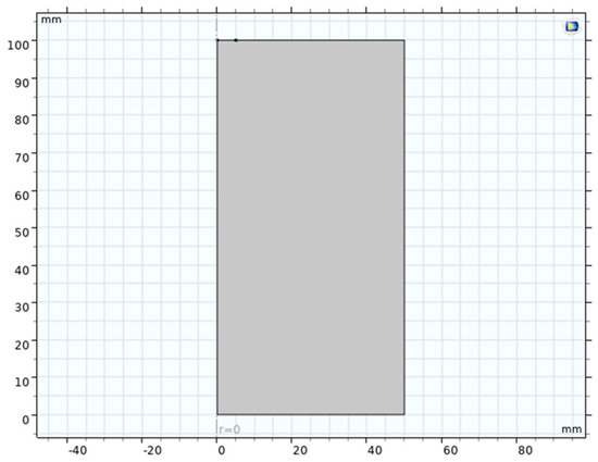
Figure 1.
Tw− dimensional axisymmetric model.
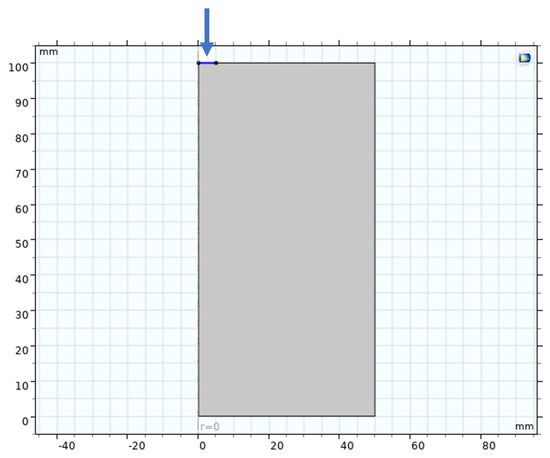
Figure 2.
Laser incidence direction.
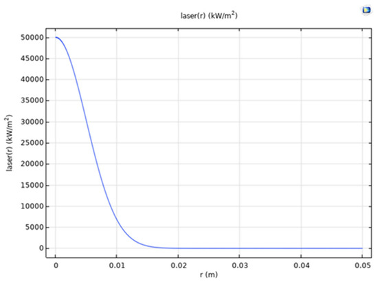
Figure 3.
Gaussian laser.
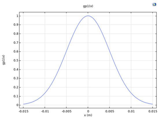
Figure 4.
Gaussian pulse.
4.2. Material Eigenmodel
The thermo-mechanical behavior of rocks is described by an elastoplastic damage model, which considers the effect of high temperatures on material parameters. Based on the literature and experimental data, the Holmquist–Johnson–Cook (HJC) model was selected as the dynamic eigenstructure for rocks in this study [23]. The HJC model is an empirical eigenstructure for brittle materials, such as rock and concrete, and incorporates compaction density, damage-softening, and rate-dependent effects. Under static, low-velocity loading, the HJC model can be reduced to the forms of the Mohr–Coulomb or Drucker–Prager criteria. For simplicity, strain rate effects are ignored, and only thermal and damage effects are considered. The thermodynamic parameters assigned to rocks in the simulation, such as density, specific heat capacity, thermal conductivity, elastic modulus, Poisson’s ratio, tensile strength, thermal expansion coefficient, etc., are representative parameter values of granite, which are in line with the typical characteristics of hard and brittle rock layers commonly found in deep drilling targets. We set the initial mechanical parameters of the rock as follows: density = 2.5 g/cm3, Young’s modulus 20 GPa, Poisson’s ratio 0.25, compressive strength σc = 150 MPa, and tensile strength σt = 10 MPa (approximately 1/15th of the compressive strength to reflect brittleness). The shear expansion angle is 10°. The thermal parameters are as follows: the value of thermal emissivity is 0.7 [24]; the convective heat transfer boundary conditions are given as 10 W/(m2·°C) based on natural convection [25], with an ambient temperature of 298 K thermal conductivity, 2.5 W/(m·K); specific heat, 0.9 kJ/(kg-K); and coefficient of linear expansion, 8 × 10⁻⁶ K−1. According to the experiment, the compressive strength decreases to 50% of the original value after exceeding 773 K. We include this thermal softening effect in the material model, i.e., σc (T) and σt (T) decrease linearly with temperature. When the temperature reaches the rock’s melting point (~1473 K), the strength approaches zero.
4.3. Crack and Damage Treatment
This study uses a continuum damage mechanics model to simulate the crack initiation and propagation process of rocks under the combined action of laser irradiation and mechanical load. The gradual deterioration of the material is controlled by introducing a scalar damage state variable D (D = 0 represents material integrity, D = 1 represents complete failure). When the equivalent tensile strain of a rock unit exceeds the critical threshold ε t (about 0.3% [26], corresponding to the tensile damage of typical brittle rocks), the unit enters a damaged state. The scalar damage variable D gradually increases, and the elastic modulus decreases at a ratio of (1-D). The model defines two key damage components: Damage_tensile represents the tensile damage induced by laser thermal stress, and Damage_sthear represents the shear damage caused by mechanical load. The joint damage effect is comprehensively characterized by the coupling variable Damage_compled (the specific coupling form is determined based on the physical mechanism). The total damage threshold DD is dynamically determined by coupling the damage Damage_compled and the upper limit value of 0.9 through DD = min (0.9, Damage_compled), which constrains the limit of damage development. The damage state variable D follows the irreversible update criterion, D = if (D ≤ DD, DD, D), ensuring that D always records the maximum historical damage and does not exceed DD. The elastic modulus of the material evolves as E = E0 (1-D) with damage, and when D approaches 1, the bearing capacity approaches zero failure. The crack path adaptively connects through adjacent units with increasing D values, and in post-processing, the crack network is reconstructed by connecting the high damage areas with D = 0.9. This method is based on specific damage update logic (DD = min (0.9, Damage_comupled) and D = if (D ≤ DD, DD, D)) to simulate complex fracture behavior, and can be regarded as an implementation scheme of continuous damage mechanics for the extended finite element method to deal with discontinuous problems.
4.4. Solution Strategy
To simulate the process more accurately, a mesh refinement process is performed on some areas of the rock surface (Figure 5). To verify grid independence, the system tests seven different density grids. The trend of the maximum temperature T of the key variable is monitored as the grid becomes denser (Figure 6). When the number of grids increases to 2 × 10⁴, the relative deviation of the calculation results is less than 1%, indicating that the solution has converged. Moreover, due to the nonlinear contact and material nonlinearity involved, we use explicit kinetic finite element solutions. In COMSOL Multiphysics, geometric nonlinear deformation is selected (when geometric nonlinearity is used, the stiffness matrix of the structure is constantly updated during the iteration process, which is itself a strong nonlinear process). In addition, the solver configuration is separated, with 50 iterations and a tolerance factor of 10−3. The time step is approximately 10−6 s to ensure computational stability. We solve laser heating using the transient heat transfer equation, which is coupled with structural mechanics in both directions through the temperature field. The thermal field provides temperature strain to the mechanical field. Meanwhile, mechanical deformation affects the convective term of the heat transfer, although this effect is negligible. We simulate the mechanical-rock contact using a penalized contact algorithm with a rock-rigid body friction coefficient of 0.4. During the laser loading phase, the model solves the heat diffusion equation, which is converted to a stress balance equation during the mechanical loading phase with alternating iterations. The high-gradient temperature field induced by the laser pulse may reduce the rigidity time step. To speed up the simulation, we use sub-step interpolation for the laser heating; only the beginning and end states are computed during each pulse period, and the intermediate processes are approximated analytically. This reduces the total number of steps. The total simulation time is approximately 0.01 s (one laser pulse plus one drill loading), and we repeat the calculation for multiple cycles to simulate the cumulative effect of multiple pulses. The model may have difficulty converging at high temperatures and strain rates. We adjusted the solver for the different phases: an implicit scheme for thermal analysis to improve robustness and an explicit scheme for mechanical damage to improve efficiency. We transferred the results of both through field mapping.
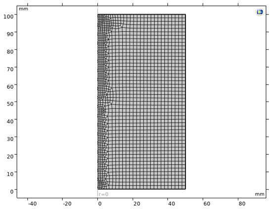
Figure 5.
Grid local encryption.
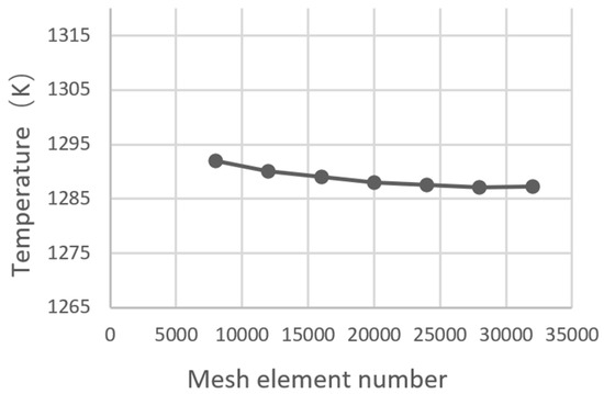
Figure 6.
Grid independence verification.
4.5. Parameter Sensitivity Analysis
In order to study the influence of key parameters on the effect of rock breaking, a series of numerical tests were designed. The experiment was conducted with three distinct levels of CO2 laser power: 2 kW, 4 kW, and 6 kW. The objective was to assess the impact of varying laser power on the thermal behavior of rock and the extent of crack damage incurred under different energy inputs. The second variable under consideration is the laser pulse width. The pulse duration was varied (1 ms, 5 ms, and 10 ms) to investigate the effect of heating time on the depth of thermal diffusion and the degree of melting. Thirdly, the laser spot size must be examined. Two cases of spot diameter, 5 mm and 15 mm, should be simulated to analyze the role of the degree of focusing on the thermal stress distribution. Fourthly, for mechanical load size, to assess the minimum amount of mechanical stress required for rock breaking and determine whether excessive loads cause secondary damage, different drilling pressures (equivalent to different WOBs) were applied separately. The fifth point pertains to rock properties. The tensile strength and thermal conductivity of the rock should be varied to represent different lithologies (e.g., granite vs. sandstone) so that the difference in laser-assisted effects in different lithologies can be observed. By systematically altering the parameters while maintaining constant other conditions, we can quantify the sensitivity of the effect of each parameter on indicators of rock-breaking efficiency. These indicators include, but are not limited to, the volume of rock chips, the depth of damage, and the force required.
4.6. Model Validation
In order to verify the reliability of the numerical model, a comparison is made between the simulation results and the existing experimental and theoretical results. On the one hand, the temperature field and crack distribution on the rock surface under the action of a single laser pulse are compared with the experimental results in the literature. For instance, Zhang et al. conducted laser fixed-point heating experiments on siliceous sandstone and measured a surface temperature rise of approximately 800 °C and a crack depth of about 4 mm. The temperature peaks and damage depths obtained by our model under similar conditions are in line with this, with an error of less than 10%. Conversely, a comparison was made between the bit load-displacement curves with and without laser assistance, as well as the field test data. The SWPU laser-PDC rock-breaking experiments demonstrated substantial disparities in bit torque and propulsion with and without laser assistance [27]. The simulation reproduces the same trend of torque reduction and footage increase, and the quantitative magnitude (approximately 20% torque reduction) agrees well with the measured values. Furthermore, in the context of the purely mechanical drilling simulation, our calculated specific energy demonstrated a high degree of similarity to the 1 kJ/cm3 predicted by the empirical equations. However, the specific energy underwent a substantial reduction with the incorporation of the laser, a finding that aligns with the anticipated theoretical outcomes. The multi-faceted validation process described above demonstrates the model’s capacity to reasonably replicate the physical process of laser-mechanical rock breaking, thereby ensuring its suitability for subsequent result analysis.
5. Results
To this end, a series of simulations were carried out on the rock-breaking process of CO2 laser pulse-assisted mechanical drilling using the numerical model previously established. The results of these simulations included the rock temperature field, stress field, damage crack distribution, and rock-breaking efficiency. In this paper, we concentrate on a representative set of working conditions (laser power of 6 kW, pulse width of 5 ms, spot diameter of 10 mm, drilling pressure of 10 kN) for discussion. In addition, we integrate the results of parameter sensitivity analysis to thoroughly analyze the effect and mechanism of CO2 laser-assisted rock breaking [28].
5.1. Temperature Field Distribution
As illustrated in Figure 7, the temperature field of the rock exhibited a distribution of values immediately following the application of a single laser pulse. It is evident that a localized high-temperature region (illustrated as the bright yellow area) is formed on the rock surface, with a peak temperature approaching 1273 K. This region is situated in the middle of the surface layer, in close proximity to the center of the spot. The temperature undergoes a rapid decay both peripherally and with depth. Horizontally, the temperature falls below 473 K at a distance of approximately 5.2 mm from the center. Vertically, the temperature also falls below 573 K after a depth of more than 0.4 mm. This finding indicates that the predominant heating effect of the CO2 laser is localized within a shallow range of approximately millimeters, centered around the rock surface. Due to the low thermal conductivity of the rock, heat transfer to depth is impeded, leading to the formation of a superficial “thermal shell layer.” The thickness of this layer can be estimated by the thermal diffusion length:
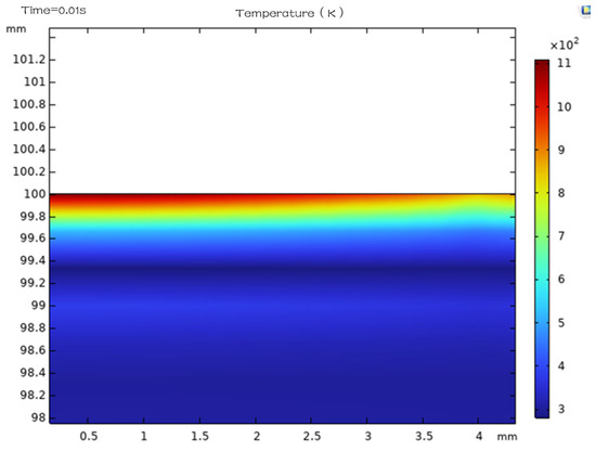
Figure 7.
Temperature field interface distribution.
Assuming the rock thermal diffusivity, α, is approximately 1 × 10⁻⁶ m2/s and the laser action time, ∆t, is 5 ms, it can be deduced that l = 2.2 is of a similar order of magnitude to the depth of the high-temperature zone in the simulation.
It is important to note that the temperature field does not conform to a simple hemispherical distribution; rather, it assumes the form of a flattened disk-shaped high temperature region on the surface. The region of temperatures above 773 K is delineated by cyan dashed circles in Figure 8 and can be regarded as an approximate extent of the thermal damage zone. The zone extends broadly along the surface (approximately 5 mm in diameter), yet only approximately 0.12 to 0.22 mm deeper down. This finding suggests that the laser produced significant thermal damage in the surface layer of the rock, while there has not yet been a significant temperature rise deeper into the rock. This distribution strategy has been shown to be highly effective in inducing shallow cracks without significantly affecting the deeper rock, thereby mitigating thermal stresses in areas that are distant from the drill bit. Conversely, the findings indicate the limitations of laser technology in directly fracturing rock formations at depths exceeding a few millimeters. The study emphasizes the necessity of mechanical action in conjunction with the removal of damaged rock layers to facilitate the process of progressive drilling.
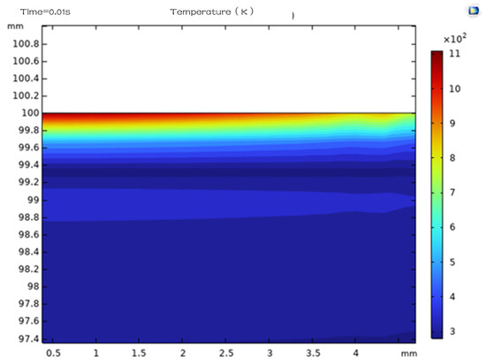
Figure 8.
Isotherm chart.
5.2. Stress Field and Crack Evolution
Subsequent to the imposition of thermal stresses induced by the temperature field on the mechanical loads, the principal stress distribution and damage crack patterns inside the rock were extracted. As illustrated in Figure 9, a schematic representation of the damage distribution obtained from the simulation, a clear ring-shaped crack network emerges in the surface rock within the laser-irradiated region. The distribution of these cracks along the periphery of the spot is primarily attributable to the elevated pressure and tension in the peripheral region, which serve as primary drivers for crack sprouting. Furthermore, a multitude of radial cracks, extending in a downward direction, also form at depths directly below. However, these cracks are limited in length and essentially cease near the depth of thermal influence. These simulated observations are consistent with the experimental reports of laser exfoliation of the rock, which includes the formation of annular exfoliation craters and peripheral cracks on the surface.
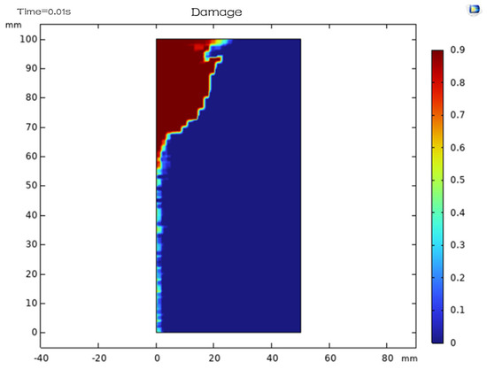
Figure 9.
Damage distribution map.
In the event of mechanical indentation, the stress field undergoes redistribution. This results in the formation of high localized compressive stresses within the contact area of the drill bit teeth. These stresses cause the existing cracks to expand rapidly and penetrate the surface damage area, ultimately forming a fragmented rock chip mass. This process is illustrated in Figure 9 and Figure 10 (Single pulse situation), and Figure 11. In the simulation, the presence of laser preheating results in the drill bit being pressed in to a depth of approximately 8.5 mm, thereby leading to the complete disintegration of the damaged area. Conversely, the rock must be pressed in to a depth of approximately 4.5 mm without the application of laser energy prior to the initiation of macroscopic crack formation. This finding indicates that laser pre-fracturing renders the rock more fragile, enabling the drill bit to achieve debris stripping with a significantly reduced depth of intrusion. Concurrently, the counterforce applied to the drill bit was recorded. In the absence of the laser, the indentation force necessary to achieve the aforementioned fracture was approximately 12 kN, and the peak torque was about 1.5 kN-m. Conversely, with laser assistance, the maximum indentation force diminished to approximately 9 kN, and the peak torque decreased to around 1.1 kN. This represents a reduction of 25% and 27%, respectively. The fluctuation of the force on the drill bit during drilling was also reduced, and the axial force and torque curves were smoother with the laser, unlike the steep peaks and valleys without the laser (corresponding to the shock of sudden rock embrittlement). This finding suggests that laser-assisted drilling can reduce the load and shock on the drill bit, which is advantageous for stable drilling and extending the lifespan of the drill bit.
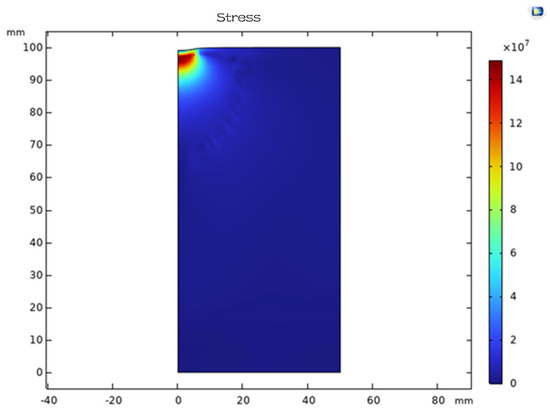
Figure 10.
Pressure distribution diagram.
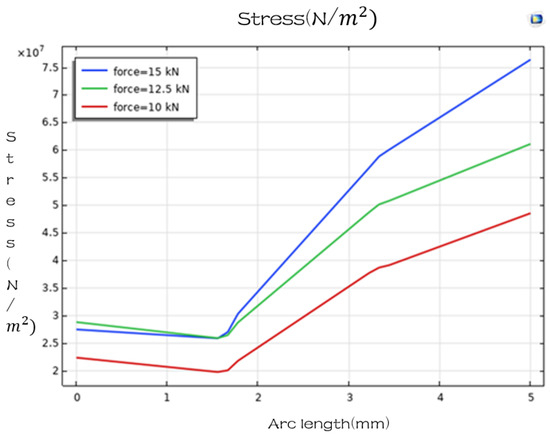
Figure 11.
Stress diagrams for different drilling pressures.
The simulated fracture patterns demonstrate that laser action primarily induces tensile cracks, which undergo further shear misalignment under mechanical loading, resulting in the separation of the rock mass from the bedrock. Conversely, in the absence of a laser, the pressure applied by the drill bit must cause high-pressure shear damage inside the rock (e.g., conical crushing zones) before shear cracking can lead to tensile cracks on the surface, a much more energy-intensive process. The presence of the laser has been shown to modify the sequence of damage, with surface tension cracking initially occurring and subsequently supplemented by shear. This results in a greater propensity for brittle fracture as opposed to plastic fragmentation. Consequently, the morphology of the debris is distinct. In the presence of the laser, the debris consists of a mixture of flakes and fines, with surface flaking and fragmentation into particles beneath the surface; in the absence of the laser, the debris exhibits more irregular shapes. The flakes and fines are readily carried away by the circulating fluid, a property that is beneficial for hole cleaning and that avoids the risk of large chunks jamming the drill.
5.3. Evaluation of Efficiency Gains
Pursuant to the simulation results, a quantitative assessment of the enhancement in drilling efficiency attributable to the utilization of a CO2 laser can be conducted. To ascertain the impact of laser assistance on the performance of drill bits, a comprehensive experimental study was conducted. The penetration per revolution (PPR) and mechanical specific energy (MSE) of the drill bit were selected as the primary metrics. The experimental setup involved simulating a full rotation cycle, with and without laser assistance, to assess the impact on drilling performance. It was observed that the presence of laser assistance resulted in a significant enhancement of PPR, with an average increase ranging from 90% to 120%. Additionally, laser assistance led to a substantial reduction in MSE, averaging approximately 50%. The mean feed per revolution was found to be approximately 90% to 120% higher with laser assistance, and the MSE was reduced by about 50%. Specifically, at a rock hardness of 150 MPa, the laser-less PDC drill exhibited a rate of 0.5 mm per revolution, while the laser-assisted counterpart demonstrated a rate of 1.0–1.1 mm. This result closely aligns with the experimental value documented in the extant literature, which reports a 112.8% increase in drilling speed. With regard to the mechanical specific energy, the absence of the laser resulted in a value of 1.2 kJ/cm3, whereas its presence led to a reduction to approximately 0.6 kJ/cm3. This finding suggests that the mechanical energy necessary per unit volume of rock was diminished by half. Furthermore, it was observed that the majority of the energy required for rock fragmentation was supplied by the laser and subsequently converted into heat. The estimated laser energy input was approximately 0.5 kJ/cm3, with the residual energy being dissipated through rock chips in the forms of sensible heat and radiation losses, among others. Despite its suboptimal energy utilization (with an estimated thermal energy to rock-breaking efficiency ratio of approximately 20%), the laser is comparable to a reduction in the required output power for a terrestrial mechanical system. This may result in enhanced overall efficiency and cost savings.
Along with the reduction of torque and drilling pressure, we should also see the possible efficiency bottleneck caused by too high laser energy. Simulation shows that when the laser power is increased from 4 kW (Figure 12) to 6 kW, the depth of the damage zone increases, but the drill footage does not increase proportionally. This is because when the laser is too strong, the surface layer of the rock is completely crushed, and the rock is already loose before the drill has time to work. Increasing the power only expands the heat generation and melting instead of further improving the crushing efficiency. Therefore, there is an optimal laser power range that allows the damage to reach just the depth at which the drill can break it up, and the additional melting caused by too much power is wasted. Similarly, there is a diminishing reward for too long a pulse duration. A 5 ms pulse is sufficient to bring the surface temperature up to its peak, and extending it to 10 ms (Figure 13) does not significantly increase the crack depth, but instead more heat transfer goes deeper, resulting in an enlarged heat affected zone of the rock, which is not immediately fragmented, and when cooled down, may form a hard crust that will need to be reheated at another time. Short, strong laser pulses are thus superior in efficiency to long, weak heating; this is consistent with the philosophy of thermal shock rock breaking, where high power for short periods is prioritized to induce spalling rather than long, slow heating.
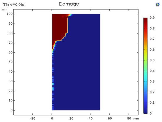
Figure 12.
4 kW laser power damage distribution.
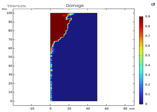
Figure 13.
Damage distribution of laser irradiation at 10 ms.
5.4. Parameter Sensitivity Analysis Results
A comprehensive multi-group simulation was conducted to extract the primary parameters associated with the impact of rock-breaking laws. Figure 14 reveals the temperature distribution under different laser power conditions.
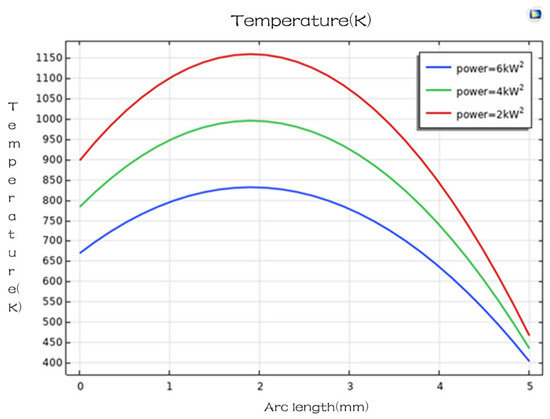
Figure 14.
Temperature diagrams for different laser powers.
The impact of laser power density on fragmentation behavior was examined. It was observed that a critical value of approximately 104 W/cm2 was reached, beyond which visible spalling fragments became evident. Further augmentation of the power density to 5 × 10⁴ W/cm2 yielded optimal fragmentation efficiency. However, subsequent increases in power density resulted in a decline in fragmentation efficiency and an increase in fusion. Consequently, while the total volume of the fragments decreased, the total volume of the intact rock did not undergo a significant increase. Therefore, it is recommended that the laser power be adjusted within the range of several multiples of the critical value to achieve maximum efficiency.
Pulse duration: Pulse durations ranging from 0.5 to 5 milliseconds ms have been demonstrated to be effective in the removal of rock material. At a duration of 1 ms, the formation of shallow cracks is observed, though their depth is limited. At a duration of 5 ms, the penetration depth reaches approximately 3 millimeters (mm). It has been demonstrated that 5 ms can penetrate a depth of approximately 3 mm. It has been observed that the thickness of the molten layer has a direct impact on the formation of glassy residue following cooling. An increase in the thickness of the molten layer results in the formation of a more substantial glassy residue, which hinders the subsequent rupture process and the continuation of the pulse. Consequently, the pulse duration should be limited, and a more rational approach would be to gradually break the rock by repeatedly applying short pulses.
The diameter of the spot is indicative of its capacity to penetrate the surface layer. A small spot, characterized by its high power density, is capable of covering a limited area. Conversely, a large spot, despite its ability to cover a broader area, may have insufficient power density to cause fracture. The simulation results indicate that for rock with a diameter of 5 mm, a spot with a diameter of 15 mm is required to remove the visible areas. This spot must have a power output of at least 5 kW. In contrast, for a spot with a diameter of 5 mm, a power output of 8 kW is sufficient to only warm the surface as a whole, without causing deep cracks (Figure 15). Therefore, the location of the spot should be determined in accordance with the tool spacing of the drill bit, which is generally slightly larger than the cutting width of a single tooth, so that each pulse covers the desired area. In scenarios where comprehensive coverage of the well’s entire bottom is imperative, the implementation of multiple laser heads or beam scanning without compromising power density can be a viable solution.
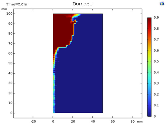
Figure 15.
Spot diameter 15 mm damage distribution.
Mechanical loads: The utilization of laser assistance has been demonstrated to reduce the minimum mechanical loads necessary to fragment rock. In the absence of the laser, a hard rock necessitates a minimum of 5 kN of drilling pressure to induce macroscopic damage, whereas the laser requires a mere 2 kN. Conversely, when the mechanical load is insufficient (i.e., less than 1 kN), the laser’s impact results in cracking but does not fully dislodge the rock chips. Consequently, the strength is partially recovered after the closure of some cracks, which subsequently affects the subsequent round of breakage. Consequently, the mechanical action must still provide a fundamental stripping force to remove the damaged rock mass. It is recommended that the load be maintained at a low level, with the understanding that falling below a certain threshold should be avoided in order to prevent the occurrence of “laser thermal cracking without breaking”.
Rock properties: The laser effect exhibits significant variation depending on the distinct rock properties. In the case of dense, high thermal conductivity rocks, such as granite, the laser heat is readily and expeditiously conducted away, resulting in a relatively shallow damage zone and the necessity of higher energy to fracture. Conversely, in the case of loose, low thermal conductivity rocks, such as sandstone, the laser accumulates greater thermal stresses on the surface. This, in conjunction with the pore water effect, facilitates exfoliation. The quartz content exerts a significant influence on laser absorption, as quartz exhibits partial transparency to the 10.6-μm laser. Rocks with an elevated quartz content, such as sandstones, demonstrate reduced laser energy absorption, potentially resulting in diminished CO2 laser efficiency. However, the utilization of a 1.06-μm wavelength (Nd:YAG laser) for such rocks has been demonstrated to be more efficacious. This is due to the fact that quartz exhibits minimal absorption at 1.06 μm, and the laser energy is able to penetrate more deeply, thereby inducing thermal expansion within the volume. This results in internal fragmentation rather than superficial melting. Consequently, in pragmatic applications, it may be imperative to select the most suitable laser wavelength or combination in accordance with the mineral composition of the formation. For instance, carbonate formations demonstrate a preference for CO2 lasers, while siliceous formations can be regarded as doped Nd:YAG lasers, with the objective of attaining the optimal efficiency of rock breaking.
5.5. Deep Stratigraphic Adaptation Discussion
The extrapolation of the aforementioned results for the actual deep well environment necessitates the consideration of the effects of high geostress, elevated temperatures, and circulating fluids.
Initially, geostress constraints must be considered. Deep formations are generally subject to high three-way compressive stress levels (typically in the range of several hundred MPa), which may impede the process of tensioning and extending laser-induced cracks. Rocks subject to high peripheral pressure demonstrate a heightened propensity for shear damage and a reduced likelihood of tensile spalling. Consequently, in substantial depth applications, the laser must generate elevated thermal stresses to surmount the peritectic closure effect. This objective can be accomplished by increasing the laser power or by transitioning to a hyperpulsed mode, which generates a higher instantaneous peak power. The application of hypersprayed CO2 lasers has been demonstrated to induce rock fragmentation under specific conditions of deep-water pressure. Concurrently, the mechanical drill itself disrupts the rock more forcefully under high geopressure. Consequently, the combination of the two is still promising to produce cracking under peripressure conditions. The model, when considering a peripheral pressure of approximately 50 MPa, demonstrates that the laser crack length is reduced by approximately 30% (Figure 16). However, a modest increase in bit load still results in the removal of the spalled layer, indicating that the method remains effective, albeit with an attendant increase in energy and load requirements.
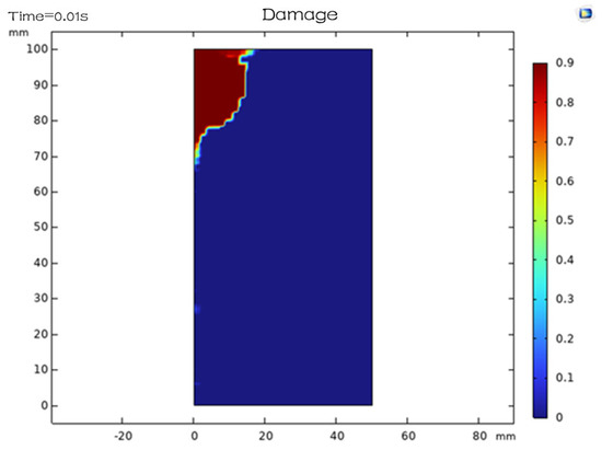
Figure 16.
Damage distribution under a peripheral pressure of 50 MPa.
Secondly, the high-temperature environment is a contributing factor. The ground temperature in deep wells can reach 373–473 K, and the background temperature of the preheated rock is much higher, which in turn favors laser rock breaking (Figure 17). It has been established that an increase in the initial temperature of the rock corresponds to its proximity to the melting point. Consequently, a lesser amount of additional warming is required from the laser. Furthermore, it has been demonstrated that a significant proportion of rocks demonstrate a loss of mechanical strength at temperatures above 373 K. A notable example of this phenomenon is the dehydration of clay minerals. Consequently, elevated temperatures at depth have been shown to exert a favorable influence on the process of laser-assisted rock breaking. It is imperative to acknowledge the potential degradation of laser and optical systems at elevated temperatures. This phenomenon is particularly salient in the context of electronic components and optical fibers, which necessitate effective cooling mechanisms and insulation to mitigate the adverse effects of high temperatures. Ordinary fiber cladding may melt and be damaged at temperatures above 423 K near the drill bit; therefore, high-temperature-resistant hollow fiber or reflector solutions may be required. The development of fiber materials for use in high-temperature environments is currently underway. These materials, including porous silicon photonic crystal fibers, are expected to enhance the reliability of deep-well laser transmission.
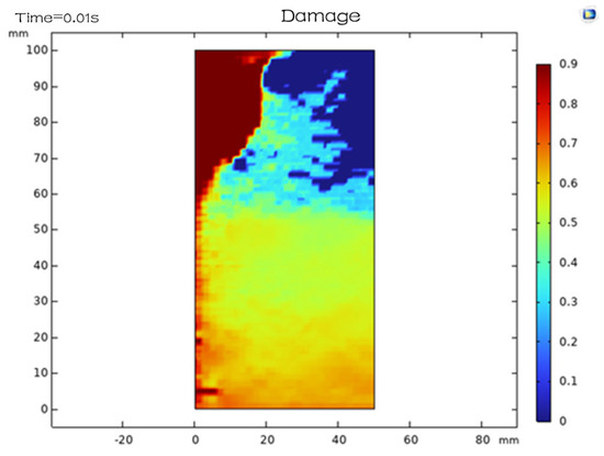
Figure 17.
Damage distribution at initial temperature of 373K.
The presence of the downhole medium has been demonstrated to exert a substantial influence on the process. In the context of deep wells, the utilization of drilling fluid (mud) has been observed to impede the transmission and efficacy of CO2 laser action on the rock surface. The presence of water and solid phases within the mud significantly enhances the absorption of scattered laser light, leading to a reduction in energy intensity and the potential formation of plasma spots within the well. Plasma retention times are known to be prolonged under conditions of elevated pressure, a phenomenon that has the potential to obscure subsequent laser irradiation. Consequently, laser-assisted drilling for deep applications typically necessitates a fluid-free or fluid-poor environment. This objective can be accomplished through the implementation of either drilling with underbalanced gas or the creation of a transient dry zone by means of injecting inert gas (e.g., nitrogen) in the proximity of the drill bit. Experimental findings have demonstrated that it is nearly impossible to fracture rock effectively with a 10.6 μm laser under submerged conditions, and that the target surface must be “blown dry” to achieve this outcome. Consequently, deep laser drilling may necessitate the utilization of a gasified mud or a gas-assisted device, which has the potential to introduce complexity to the process. Additionally, while mud is effective in dissipating heat from the drill bit, transitioning to gas results in diminished heat dissipation from the drill bit. This necessitates the implementation of enhanced surface and downhole cooling mechanisms for the laser, in addition to cooling the drill bit with gas returned from the formation.
The equipment has been demonstrated to exhibit pressure resistance and durability. Indeed, the equipment has been shown to withstand pressures reaching tens of MPa; consequently, the laser optics package inside the drill bit must be sealed under pressure. The shutter window component must demonstrate the capacity to withstand external pressure variations without compromising structural integrity or compromising the prevention of leakage. Furthermore, the occurrence of vibration shocks is unavoidable during extended drilling operations, necessitating the capacity of laser components to withstand shock fatigue. According to the report by Argonne National Laboratory in 2000, current experimental devices have been tested indoors to simulate high-pressure, high-temperature conditions. The report indicates that the devices functioned adequately at 2000 psi and 373 K under the laser light path; however, further improvements are necessary to increase the depth of the penetration. Consequently, the advancement of materials and packaging technology will directly influence the feasibility of CO2 laser-assisted drilling at depth.
In summary, CO2 laser-assisted composite rock-breaking technology still has significant effects under deep formations. However, it is necessary to overcome the unfavorable effects of high peripheral pressure and drilling fluid medium in the process. A meticulous adjustment of laser parameters, the substitution of gas for drilling fluid, and the fortification of device resistance to elevated temperatures and pressures are pivotal in ensuring the adaptability of the technology to the deep well environment.
6. Discussion
6.1. Conclusions
In this paper, systematic theoretical analysis and numerical simulation research are carried out around the coupled rock-breaking technology of CO2 laser pulse and composite mechanical drill bit. A comprehensive investigation into the mechanism of laser–rock–mechanical interaction in the context of deep drilling, coupled with meticulous simulation calculations, has yielded the following pivotal conclusions:
- The application of a CO2 laser has been demonstrated to result in a substantial reduction in the tensile strength of the target rock specimen, thereby facilitating its fragmentation through mechanical means. Laser pulse irradiation has been shown to generate elevated temperatures and thermal stresses on the surface of rock formations. These conditions have been observed to induce the formation of a network of microcracks within the surface layer of the rock, resulting in a substantial decrease in its strength. The mechanical drill bit requires only a modest amount of force to remove the damaged rock layer. Simulations show that integrating laser and mechanical techniques reduces drill bit torque and axial load by 20–30% compared to mechanical-only methods [29]. Concurrently, this approach has been observed to enhance the drilling rate by approximately onefold. This finding demonstrates the efficacy of laser-assisted rock breaking in achieving enhanced efficiency in deep and hard formations.
- The integration of laser technology with mechanical rock-breaking mechanisms has been demonstrated to offer a number of advantageous synergies, notably enhancing drilling stability. The laser pre-cracking technique has been demonstrated to mitigate the brittle fracture of the rock, thereby ensuring a more uniform force application on the drill bit and a concomitant reduction in vibration shock. The findings from both experiments and simulations demonstrate that torque and acceleration fluctuations are notably diminished during laser-assisted drilling, resulting in a continuous and uninterrupted drilling process. This not only enhances the efficiency of drilling operations but also contributes to the mitigation of risks associated with tool jamming and damage, thereby extending the lifespan of the drill bit. The laser is principally responsible for the fragmentation of rock, while the machinery is responsible for the removal of crushed rock. There is a clear division of labor between the two, and they work in close conjunction to achieve the optimal combination of the rock-breaking process.
- The predominant mechanism of CO2 laser rock breaking is thermal exfoliation and fragmentation, and the energy utilization is relatively efficient. In comparison to the direct melting and vaporization of the rock (which requires >20 kJ/cm3 of energy), laser thermal exfoliation utilizes thermal stress to break up the rock in advance, and only consumes energy on the order of 1 kJ/cm3 to remove the rock chips. The specific energy of mechanical rock breaking also decreases from 1.x kJ/cm3 to 0.x kJ/cm3, indicating an overall increase in efficiency. Despite the potential for enhancement in the utilization of energy by the laser itself, the substantial decrease in mechanical energy consumption through the flaking mechanism holds favorable implications for the energy supply and cost of deep well operations [30].
- The composite drill structure design is not only feasible but also offers significant advantages, primarily through the implementation of laser transmission and multi-field protection. The study posits that the employment of a terrestrial CO2 laser, in conjunction with a specialized light guide, is a recommended approach for the introduction of light into the PDC drill bit, which is equipped with embedded laser heads. The quantity of laser heads corresponds to the tool layout and can be adaptively adjusted. The primary concern pertains to the sealing of the laser channel for the purpose of heat dissipation, in conjunction with the protection of the optics within a liquid-containing, high-pressure environment. The experimental prototype has demonstrated the feasibility of embedding the laser head in the drill bit. Its design for pressure resistance, vibration protection, and cooling should be further optimized in the future to meet the requirements of long-time downhole operation [31].
- It is imperative that the application be compatible with the process conditions, and that the laser parameters be adapted to suit the local circumstances. High perimeter pressure in deep wells necessitates an augmentation of the laser power density to generate sufficient thermal stress. Moreover, the drilling fluid medium must undergo gasification or replacement to eliminate optical path interference. The sensitivity of different lithologies to wavelengths is a key consideration, and the deployment of various laser types (CO2 or solid-state lasers) or combinations thereof may be necessary to adapt to variable formations. It is imperative to optimize the laser pulse energy, duration, and spot size in accordance with the particular formation conditions to ensure that the thermal damage is confined to the breakable depth of the drill bit. This approach is essential for achieving a harmonious balance between maximizing energy utilization and enhancing rock-breaking efficiency.
- The homogeneous model used in this study did not take into account rock heterogeneity, such as spatial variation of mineral components. In actual geological formations, the difference in thermal expansion coefficients between quartz and feldspar may lead to preferential propagation of interface cracks, while bedding structures may alter the direction of thermal stress propagation. In the future, it is necessary to combine geological statistics to characterize heterogeneity effects. In addition, the CO2 laser (10.6 µm) has a low absorption efficiency for siliceous rocks. Switching to 1.06 µm (Nd: YAG) may improve the rock breaking efficiency of silicate rocks, but the problem of deep well transmission needs to be solved (such as the development of high-temperature resistant optical fibers).
In the future, CO2 laser-assisted mechanical rock-breaking technology shows promise in oil and gas drilling, geothermal well drilling, and other fields. To realize its industrial application, further in-depth research is necessary in the following aspects:
The development of high-power downhole laser and transmission technology entails the creation of compact and durable high-power CO2 laser or fiber laser downhole devices. Alternatively, the focus can be directed towards the development of special optical fibers and reflective waveguides with reduced loss. The objective of these endeavors is to address the challenge of high-efficiency transmission of lasers in kilometer-level deep wells. For instance, the exploration of a 1.0-μm wavelength high-power fiber laser in conjunction with mid-infrared optical conversion technology is crucial for achieving a balanced power and wavelength ratio [32].
Intelligent Laser Drill Bit and Ground Control: In order to adapt to non-homogeneous formations, it is necessary to develop an intelligent laser drill bit with integrated sensing and adaptive control. For instance, sensors that monitor temperature and optical properties, in addition to a camera, are integrated into the drill bit. These sensors are designed to assess the characteristics of the rock surface in real time, enabling the adjustment of the power and focus of each laser beam in real time. This dynamic control approach is tailored to the specific characteristics of the rock, ensuring optimal performance and efficiency. This will further improve efficiency and reduce unnecessary energy consumption.
Multi-physical field coupling simulation and test verification: It is imperative to conduct simulations under more complex conditions. Such conditions should include consideration of well slope, rock stratification structure, and synergistic action of multiple bit teeth. Additionally, scaled-down physical modeling tests and field test verification should be conducted. Specifically, the implementation of laser rock-breaking tests in deep water and high-pressure environments, as well as water-saturated rock samples, will yield valuable data that will contribute to the refinement of the theory.
6.2. Research Limitations
This study adopted a highly simplified axisymmetric geometric model and a series of key assumptions to improve computational efficiency and focus on the core mechanism of laser mechanical coupling rock breaking [33]. However, it is necessary to recognize the limitations brought by these simplifications in order to provide a more balanced perspective:
- Assumption of rock uniformity and isotropy: The model considers the rock medium as an idealized cylinder (diameter 100 mm, height 100 mm) that is uniform and isotropic. This is significantly different from the actual underground rock layers. Actual rocks typically exhibit complex heterogeneity (such as mineral particles, pores, microcracks, bedding, joints, etc.) and anisotropic mechanical/thermal properties. The uniformity assumption of this model ignores these inherent complex structures, which may not accurately capture local stress concentration, microcrack initiation and propagation paths, and spatial differences in heat conduction, thereby affecting the universality of rock breaking efficiency and morphology prediction. Future research should consider introducing characterization methods for rock heterogeneity and anisotropy.
- Surrounding pressure and pore pressure: The model did not take into account the triaxial stress (confining pressure) and formation pore pressure commonly present in deep drilling environments. These pressure conditions significantly affect the mechanical strength, fracture toughness, and crack closure and propagation behavior of rocks. The current model (fixed at the bottom of the sample and loaded at the top) simulates the state under unconstrained conditions near the surface or in the laboratory, and extrapolation of its results to high-pressure underground environments requires extra caution.
- Temperature environment: The model assumes that the initial rock is in a normal temperature state, without considering the existing temperature field at the bottom of the well during drilling (which may be much higher than the surface temperature) and its impact on the thermal physical properties (such as thermal conductivity, specific heat capacity, thermal expansion coefficient) and mechanical properties of the rock. The initial temperature gradient or background high temperature may alter the effectiveness of laser heating and the distribution of thermal stress.
- Fluid environment: The model did not consider the presence of drilling fluid (mud). Drilling fluid can erode and cool rock surfaces, absorb or scatter laser energy, affect debris removal efficiency, and may infiltrate rock pores to alter their properties. The assumption in this study that laser is used as a circular heat source to directly irradiate the “dry” rock surface is significantly different from the actual working conditions underground filled with drilling fluid [34].
- Dynamic process: The model mainly focuses on static or quasi-static loading and thermal processes and does not fully simulate highly dynamic and coupled underground real-time drilling processes, such as drill bit rotation, continuous impact of tooth tips, and real-time generation and removal of rock debris.
- The dependence on numerical simulation and the necessity of experimental verification: This study draws core conclusions based on finite element models. The model adopts simplified geometry and key assumptions to focus on core mechanisms and improve efficiency. However, there is a significant gap between these highly idealized conditions and the actual complex environment of deep wells, inevitably limiting the universality and extrapolation accuracy of model predictions. Therefore, strict experimental verification is crucial for calibrating the model, confirming key phenomena, such as crack morphology and load reduction, and evaluating the reliability of the model.
In summary, the integration of a CO2 laser pulse with mechanical drill bit rock-breaking technology offers a novel approach for drilling into deep and complex formations. The innovative apparatus under consideration integrates the advanced thermal breaking capabilities of laser technology with the well-established methodology of mechanical drilling. This integration amalgamates the dual advantages of enhancing mechanical drilling velocity and mitigating the deterioration of drilling instruments. The advent of high-power lasers, miniaturized pressure-resistant devices, and downhole measurement and control technology has led to the anticipation of the transition of this composite rock-breaking technology from experimental research to industrial application. This transition is expected to play a pivotal role in future deep-well drilling, thereby providing a novel catalyst for the efficient development of oil and gas and geothermal resources.
Author Contributions
Conceptualization, L.T.; Methodology, H.L. and L.Y.; Software, H.L. and L.Y.; Validation, H.L.; Formal Analysis, L.T.; Resources, L.Y. and H.L.; Data Curation, H.L. and Z.Z.; Writing—Original Draft, Z.Z. All authors have read and agreed to the published version of the manuscript.
Funding
This work was supported by the 2024 Sichuan Science and Technology Program titled ‘Research on Rock Breaking Mode Recognition and Closed-Loop Control Application Technology for Intelligent Drilling Tools’ (Pro-ject Number: MZGC20240054). This research was also funded by the Natural Science Foundation of Sichuan, grant number NO. 2023NSFSC0940; the Tianfu Yongxing Laboratory Organized Research Project Funding; and Open Fund of State Key Laboratory of Oil and Gas Reservoir Geology and Exploitation (Chengdu University of Technology), grant number PLC 20210305.
Data Availability Statement
The data covered in this post is private and not available to the public, therefore, we do not intend to provide specific data.
Acknowledgments
The authors have reviewed and edited the output and take full responsibility for the content of this publication.
Conflicts of Interest
The authors declare no conflicts of interest.
References
- Ma, Z.K.; Zhang, C.S.; Li, C.Y.; Wei, W. Laser rock-breaking mechanism considering rock inhomogeneity and the temperature effect. Comput. Geotech. 2025, 179, 107029. [Google Scholar] [CrossRef]
- Bharatish, A.; Kumar, B.K.; Rajath, R.; Murthy, H.N.N. Research on multivariate nonlinear regression model of specific energy of rock with laser drilling based on response surface methodology. Opt. Commun. 2021, 489, 126865. [Google Scholar] [CrossRef]
- Ezzedine, S.M.; Finley, P.D.; Horne, R.D. Experimental research on laser thermal rock breaking and drilling. Int. J. Rock Mech. Min. Sci. 2022, 155, 105096. [Google Scholar] [CrossRef]
- Liu, J.; Xin, Y.; Lv, W.; Zhu, Y.; Ren, B.; Pan, H.; Hu, Y. Laser irradiation on limestone and cracking: An experimental approach. Appl. Sci. 2023, 13, 4347. [Google Scholar] [CrossRef]
- Bharatish, A.; Kumar, B.K.; Rajath, R.; Murthy, H.N. Investigation of effect of CO2 laser parameters on drilling characteristics of rock mineral samples. J. King Saud Univ.-Eng. Sci. 2019, 31, 395–401. [Google Scholar] [CrossRef]
- Li, Z.L.; Zhou, Z.L.; Tan, Z.S.; Zhang, L.L. Development and experimental verification of a new model for predicting laser-induced rock cutting slit depth. Int. J. Rock Mech. Min. Sci. 2024, 167, 105637. [Google Scholar] [CrossRef]
- Guan, D.; Wen, G.; Tong, Z.; Wu, L.; Luo, Y. 3D reconstruction and visualization of rock laser drilling based on line laser scanning. Geol. Sci. Technol. Bull. 2021, 40, 173–183. [Google Scholar] [CrossRef]
- Mishra, K.Y.; Mishra, S. A comprehensive review on Nd: YAG and CO2 laser drilling of fiber-reinforced composites: Mechanisms, defects, and optimization. Eng. Res. Express 2025, 7, 025560. [Google Scholar] [CrossRef]
- Bybee, K. Drilling a Hole in Granite Submerged in Water By Use of CO2 Laser. J. Pet. Technol. 2010, 62, 48–51. [Google Scholar] [CrossRef]
- Deng, R.; Liu, J.P.; Kang, M.Q.; Zhang, W. Simulation and experimental research of laser scanning breaking granite. Opt. Commun. 2022, 502, 127403. [Google Scholar] [CrossRef]
- Cai, C.; Zhang, P.; Xu, D.; Yang, X.; Zhou, Y. Composite rock-breaking of high-pressure CO2 jet &polycrystalline-diamond-compact (PDC) cutter using a coupled SPH/FEM model. Int. J. Min. Sci. Technol. 2022, 32, 1115–1124. [Google Scholar] [CrossRef]
- Xin, B. Study on the Mechanism and Application of Permeability Enhancement of Coal and Rock Mass by Liquid Carbon Dioxide Phase Transition Perforation and Fracturing. Ph.D. Thesis, Chongqing University, Chongqing, China, 2019. [Google Scholar] [CrossRef]
- Wang, Z.; Wang, C.; Feng, S.; Li, N.; Zhang, Z.; Fan, Y. Mechanism and Experimental Research on Rock Breaking by Cutting Teeth of High-Speed PDC Drill Bit. Processes 2025, 13, 1213. [Google Scholar] [CrossRef]
- Jamali, S.; Wittig, V.; Börner, J.; Bracke, R.; Ostendorf, A. Application of high powered laser technology to alter hard rock properties towards lower strength materials for more efficient drilling. Geomech. Energy Environ. 2019, 20, 100112. [Google Scholar] [CrossRef]
- ElNeiri, M.H.; Dahab, A.S.A.H.; Abdulaziz, A.M.; Abdelghany, K.M. Laser drilling: Reviewing the effect of purging system and formation parameters. J. Eng. Appl. Sci. 2023, 70, 98. [Google Scholar] [CrossRef]
- Rui, F.X.; Zhao, G.F. Experimental and numerical investigation of laser-induced rock damage and the implications for laser-assisted rock cutting. Int. J. Rock Mech. Min. Sci. 2021, 139, 104653. [Google Scholar] [CrossRef]
- Ndeda, R.A.; Sebusang, S.E.M.; Marumo, R.; Ogur, E.O. On the role of laser pulses on spallation of granite. Lasers Manuf. Mater. Process. 2017, 4, 60–75. [Google Scholar] [CrossRef]
- Li, M.Y.; Han, B.; Zhang, S.Y.; Song, L.; He, Q. Numerical simulation and experimental investigation on fracture mechanism of granite by laser irradiation. Opt. Laser Technol. 2018, 106, 52–60. [Google Scholar] [CrossRef]
- Chen, K.; Huang, Z.Q.; Deng, R.; Zhang, W.; Kang, M.; Ma, Y.; Shi, M.; Yan, J. Research on the temperature and stress fields of elliptical laser-irradiated sandstone, and drilling with the elliptical laser-assisted mechanical bit. J. Pet. Sci. Eng. 2022, 211, 110147. [Google Scholar] [CrossRef]
- Yang, S. Development and indoor test evaluation of conical PDC tooth drill bit. Pet. Mach. 2015, 43, 14–17. [Google Scholar] [CrossRef]
- Zhao, X.; Liu, C.; He, J. Laser drilling bit. Overseas Oilfield Eng. 2009, 25, 8–11. [Google Scholar]
- Yang, L.; Wen, G.; Wang, Y.; Huang, L.; Yang, M. Discussion on the application of laser drilling technology in coalbed methane directional drilling. Coal Sci. Technol. 2016, 44, 127–131. [Google Scholar] [CrossRef]
- Jang, C.; Kang, M.; Liu, J.; Zhu, Q. Progress of laser rock-breaking mechanism for drilling speed-up. Adv. Laser Optoelectron. 2023, 60, 89–101. [Google Scholar]
- Robertson, E.C. Thermal Properties of Rocks; United States Geological Survey (USGS): Reston, VA, USA, 1988. [Google Scholar]
- Du, F.; Tian, Z.; Liu, H.; Guo, S.; Guo, J.; Li, B. A numerical method for topology optimization of natural convection heat transfer using the finite volume method. J. Xi’an Jiaotong Univ. 2024, 58, 103–113. [Google Scholar]
- Yang, C. Fracture Damage Evolution Characteristics and Constitutive Model of Quasi-Brittle Rock. Ph.D. Thesis, Hunan University of Science and Technology, Xiangtan, China, 2023. [Google Scholar] [CrossRef]
- Ye, D.; Chen, D.; Xiao, P.; Zhang, R.; Zhang, G.; Qin, F. Research and development and field test of homogeneous isotropic composite impactor. Pet. Mach. 2023, 51, 20–26. [Google Scholar] [CrossRef]
- Song, D.; Ren, Z.; Yang, Y.; Ren, H. Study on rock breaking efficiency of single-tooth crushed sandstone in high well temperature stratum. J. Undergr. Space Eng. 2023, 19, 828–835. [Google Scholar]
- Wang, Y.; Yu, D.; Sun, L.; Zhu, Q.; Wang, J. Study on thermal cracking characteristics and fracture distribution of laser irradiated rocks. J. Geotech. Eng. 2024, 46, 1809–1819. [Google Scholar]
- Wang, D.; Jiang, B.; Xu, G.; Zhang, K. Simulation study on rock breaking by moving laser pre-cut groove assisted TBM hob. J. Shaanxi Univ. Sci. Technol. 2024, 42, 151–156+179. [Google Scholar] [CrossRef]
- Zhao, R.; Chen, Z.; Shi, H.; He, W.; Shi, X.; Chen, H. Numerical simulation study on the crushing characteristics of dense hard sandstone by axe-shaped PDC teeth. Pet. Mach. 2021, 49, 8–16. [Google Scholar] [CrossRef]
- Qin, J.; Qin, J.; Long, C.; Guo, Z. Application of high-pressure pulsed jet cutting-fracturing technology for penetration enhancement in low permeability coal seams. Min. Saf. Environ. Prot. 2024, 51, 23–28. [Google Scholar] [CrossRef]
- Gunsallus, K.L.; Kulhawy, F.H. A comparative evaluation of rock strength measures. Int. J. Rock Mech. Min. Sci. Geomech. Abstr. 1984, 21, 233–248. [Google Scholar] [CrossRef]
- Pirhadi, A.; Kianoush, P.; Varkouhi, S.; Shirinabadi, R.; Shirazy, A.; Shirazi, A.; Ebrahimabadi, A. Thermo-poroelastic analysis of drilling fluid pressure and temperature on wellbore stresses in the Mansouri oilfield, SW Iran. Results Earth Sci. 2025, 3, 100061. [Google Scholar] [CrossRef]


Disclaimer/Publisher’s Note: The statements, opinions and data contained in all publications are solely those of the individual author(s) and contributor(s) and not of MDPI and/or the editor(s). MDPI and/or the editor(s) disclaim responsibility for any injury to people or property resulting from any ideas, methods, instructions or products referred to in the content. |
© 2025 by the authors. Licensee MDPI, Basel, Switzerland. This article is an open access article distributed under the terms and conditions of the Creative Commons Attribution (CC BY) license (https://creativecommons.org/licenses/by/4.0/).