Article

Analytical Prediction of Fatigue Life for Roller Bearings Considering Impact Loading

1
School of Mechanical and Precision Instrument Engineering, Xi’an University of Technology, Xi’an 710048, China
2
School of Water Resources and Hydropower, Xi’an University of Technology, Xi’an 710048, China
*
Author to whom correspondence should be addressed.
Processes 2025, 13(8), 2545; https://doi.org/10.3390/pr13082545
Submission received: 13 July 2025 / Revised: 4 August 2025 / Accepted: 10 August 2025 / Published: 12 August 2025

Abstract

During the actual operating conditions, it is inevitable that rolling bearings will be subjected to impact loading. However, due to the very short duration of impact loading, previous studies have almost ignored the influence of impact loading on fatigue life of roller bearings. This paper attempts to construct a numerical framework to address the above issues, thereby providing a theoretical basis for predicting fatigue life of roller bearings under frequent impact loading. A quasi-dynamic model of roller bearings is established to capture the instantaneous fluctuation in roller–raceway contact loads due to impact loading. Then, the influence of impact loading on the fatigue life of roller bearings is accurately characterized based on Miner’s rule. The results show that the frequent impact loading causes a significant decrease in the fatigue life of roller bearings, and the extent of fatigue life decrease depends on the bearing speeds and load conditions. To accurately predict the fatigue life of roller bearings under actual operating conditions, it is necessary to account for the influence of the impact loading, especially for high speeds and light load conditions.

1. Introduction

Material spalling on bearing components is a leading cause of fatigue failure in rolling bearings, ultimately impacting the reliability and safety of a mechanical system. Over the years, researchers and manufacturers have extensively investigated the factors influencing fatigue life of rolling bearings and developed numerous numerical models to address the life prediction issue. The Lundberg–Palmgren model (L-P model) [1] provided a numerical method for predicting the fatigue life of rolling bearings based on bearing test data and the Weibull distribution theory, which is one of the first significant advancements in this area. Chiu [2] later refined the L-P model by incorporating the effects of material inclusions, improving its accuracy and practical application. Tallian [3] expanded on these efforts by proposing a two-phase fatigue mechanism that accounts for both crack initiation and propagation, which effectively explains the excess life of bearings in the early failure region. Ioannides and Harris [4,5] further advanced the field by introducing a stress criterion equation to address a key limitation of the L-P model, which is the inability to predict bearings with infinite fatigue life. To date, the L-P model is still the most prevalent method in both theoretical research and practical engineering, which has been widely adopted by industry, national, and international standards [6,7,8,9,10].
To accurately predict the fatigue life of rolling bearings in mechanical systems, the modeling process must comprehensively incorporate assembly parameters and operating conditions. Oswald [11], Takahashi [12], and Fang [13] demonstrated that the internal clearances, including both axial and radial, have a significant influence on the fatigue life of rolling bearings, and further proposed a clearance optimization strategy aimed at maximizing fatigue life under varying operating conditions. Tong [14,15] and Zhang [16] studied the significant change in fatigue life of rolling bearings due to ring angular misalignment. With the increasing demand for accuracy in rolling bearing life prediction, factors like preload [17,18] and thermal expansion of bearing components [19,20] have been integrated into the fatigue life model. However, these models are typically restricted to steady load conditions and cannot be directly applied to variable load scenarios.
Many researchers have attempted to quantify the influence of variable loading on bearing fatigue life based on the damage cumulative theory [21,22,23,24]. However, to the extent of the authors’ knowledge, these studies almost neglect the instantaneous fluctuations in contact loads between rollers and raceways due to variable loads. As a result, for smooth variable loading conditions originating from rotor mass imbalance, the bearing life prediction based on the above studies has acceptable engineering accuracy. In contrast, for frequently impact loading conditions originating from harsh environments and mechanical parts wear [25,26,27,28,29], the bearing life prediction based on the above studies will fail to characterize the acceleration fatigue of rolling bearings. A clear rule is that to accurately predict the influence of impact loading on roller bearing fatigue life, the instantaneous fluctuation in roller–raceway contact load should first be determined.
This paper attempts to construct a numerical framework to accurately evaluate the influence of impact loading on fatigue life of roller bearings. A quasi-dynamic model of roller bearings is established first to capture the instantaneous fluctuation in roller–raceway contact load caused by impact loading. Subsequently, based on the fatigue damage accumulation theory and a series of ISO standards, the cumulative fatigue damage model of bearing components is established to characterize the influence of instantaneous fluctuations in roller–raceway contact loads. Finally, the constructed numerical framework is utilized to examine the influence of impact loading on the fatigue life of roller bearings, and the decrease in fatigue life of roller bearings caused by impact loading under various loads and speed conditions is detailed and analyzed. Compared with the fatigue life models widely used in the engineering field today, the method constructed in this paper can more accurately characterize the effect of impact loading on the fatigue life of roller bearings.

2. Theoretical Analysis

2.1. Quasi-Dynamic Model of Roller Bearings

Since the contact loads between rollers and raceways are the primary cause of bearing fatigue failure, this study only considers the three translational degrees of freedom that determine the contact loads between rollers and raceways. As shown in Figure 1, taking tapered roller bearings (TRBs) as an example, and assuming that the inner ring is moving and the outer ring is stationary, the 3-degree-of-freedom (3-DOF) quasi-dynamic model for TRB behavior is established in the O-XYZ coordinate system and is expressed as follows:
m x ¨ + c x x ˙ + k x x = F x m y ¨ + c y y ˙ + k y y = F y m z ¨ + c z z ˙ + k z z = F z
where m is the quality of inner ring; kx, ky, and kz are the integrated stiffnesses of bearings; cx, cy, and cz are the integrated dampings of bearings; Fx, Fy, and Fz are the external loads acting on bearings; x, y, and z are the displacements of inner rings; x ˙ , y ˙ , and z ˙ are the velocities of inner rings; and x ¨ , y ¨ , and z ¨ are the accelerations of inner rings.
In Equation (1), the X-axis and Y-axis correspond to the orthogonal radial directions of the tapered roller bearing shown in Figure 1, respectively, while the Z-axis corresponds to the axial direction of the tapered roller bearing shown in Figure 1. The integrated stiffness and integrated damping of TRBs are determined by the contact stiffness and oil film damping between each roller and raceway. Based on the relative positional relationship between the O-XYZ coordinate system and each roller shown in Figure 1, the integrated stiffness and integrated damping can be expressed as Equations (2) and (3).
k x x = j = 1 n r Q jo cos α o cos φ j k y y = j = 1 n r Q jo cos α o sin φ j k z z = j = 1 n r Q jo sin α o
c x x ˙ = j = 1 n r F djo cos α o cos φ j c y y ˙ = j = 1 n r F djo cos α o sin φ j c z z ˙ = j = 1 n r F djo sin α o
where Qjo and Fdjo are the contact load and oil film damping force between the jth roller and outer ring, respectively; αo is the roller–outer raceway contact angle; φj is the angular position of the jth roller; and nr is the number of rollers inside the roller bearing.
The contact load between the jth roller and outer raceway is calculated by
Q jo = K δ jo 10 / 9
where K is the contact stiffness factor between rollers and raceways. δjo is the elastic deformation between the jth roller and outer raceway. Ignoring slight geometric differences between the inner raceway and outer raceway, δjo is determined by the displacement of the inner ring and can be calculated by
δ jo = max x cos α o cos φ j + y cos α o sin φ j + z sin α o 2 , 0
For steel roller–steel raceway contact, the contact stiffness factor K is given by [30]
K = 8.06 × 10 4 l e
where le is the effective contact length between rollers and raceways.
The oil film damping force between the jth roller and outer raceway is calculated by
F djo = c v jo
where c is the oil film damping factor between rollers and raceways. vjo is the normal oil film extrusion speed between the jth roller and outer raceway, which is calculated by
v jo = max x ˙ cos α o cos φ j + y ˙ cos α o sin φ j + z ˙ sin α o 2 , 0
The oil film damping between the roller and the raceway depends on the oil film thickness and the oil film squeeze rate. Based on the Reynolds equation, the oil film damping factor between rollers and raceways can be represented as [31]
c = 6 π η 0 R 1.5 l e 2 h c 1.5
where η0 is the lubricant viscosity in atmospheric conditions; R is the equivalent curvature radius between a roller and raceway; and hc is the center oil film thickness between a roller and raceway, which is calculated by an amended oil film thickness formula as [32]
h c = 11.9 α 0 0.4 η 0 u 0.74 R 0.46 E 0.14 w 0.2
where α0 is the pressure–viscosity coefficient of the lubricant; u is the entrainment velocity between a roller and raceway; E′ is the equivalent elastic modulus between a roller and raceway; and w is the contact load per unit length between a roller and raceway.
During the operation of tapered roller bearings, angular position of each roller changes continuously, and their changes over time can be expressed as
φ j = φ j 0 + π n 60 ( 1 γ ) t
Correspondingly, the entrainment velocity between each roller and raceway is calculated by
u o = π d m n 120 1 γ 2 ( 1 + cos α o )
u i = π d m n 120 1 γ 2 ( 1 + cos α i )
where φj is the angular position of the jth roller after running time t; φj0 is the initial angular position of the jth roller; uo is the entrainment velocity between a roller and outer raceway; ui is the entrainment velocity between a roller and inner raceway; dm is the pitch diameter of bearing; n is the bearing speed; αo is the roller–outer raceway contact angle; αi is the roller–inner raceway contact angle; and γ is the bearing geometry coefficient and given by Equation (14).
γ = D cos α / d m
where D is the mean diameter of the roller and α is the mean contact angle between rollers and raceways, which is calculated by
α = ( α o + α i ) / 2

2.2. Fatigue Life Model of Roller Bearings

To predict the fatigue life of roller bearings, the fatigue lives of bearing components are statistically combined using the product law and expressed as
L = L o 9 / 8 + L i 9 / 8 8 / 9
where Lo is the fatigue life of the outer raceway and Li is the fatigue life of the inner raceway.
According to ISO TS16281-2008 [9], the fatigue life of inner and outer raceways can be given as
L o , i = Q c / Q e 4
where Qe is the equivalent load for roller–raceway contact and Qc is the basic dynamic capacity for roller–raceway contact. Considering the effect of contact load non-uniform distribution such as stress concentrations, the basic dynamic capacity for roller–raceway contact can be represented as [30]
Q c = 522 λ 1 γ 29 / 27 1 ± γ 1 / 4 γ cos α 2 / 9 D 29 / 27 l e 7 / 9 n r 1 / 4
where λ is the reduction factor for basic dynamic capacity. The upper signs refer to roller–inner raceway contact and the lower signs refer to roller–outer raceway contact.
Assume that the inner ring of bearing is moving and its outer ring is stationary, the equivalent rolling element load for roller–raceways contact can be represented as
Q ei = 1 n r j = 1 n r Q ji 4 1 / 4
Q eo = 1 n r j = 1 n r Q jo 4.5 1 / 4.5
where Qei is the equivalent load for roller–inner raceway contact; Qeo is the equivalent load for roller–outer raceway contact; Qjo is the contact load between the jth roller and outer raceway; and Qji is the contact load between the jth roller and inner raceway.
Miner’s rule is applied to describe the cumulative fatigue damage caused by fluctuating contact loads between rollers and raceways, and then the fatigue damage accumulation rating life model is established as follows:
D ac = k = 1 n n k Δ t L k
where Δt is the time step size; nk is the bearing speed in kth time step; Lk is the potential fatigue life corresponding to the roller–raceways contact load in kth time step; and Dac is the fatigue damage accumulation coefficient. When the Dac value reaches the threshold value, the fatigue failure of the bearing occurs. The threshold value for Dac is set to 1 in this paper; however, it should be noted that for special working conditions, other values can also be set according to the test results.
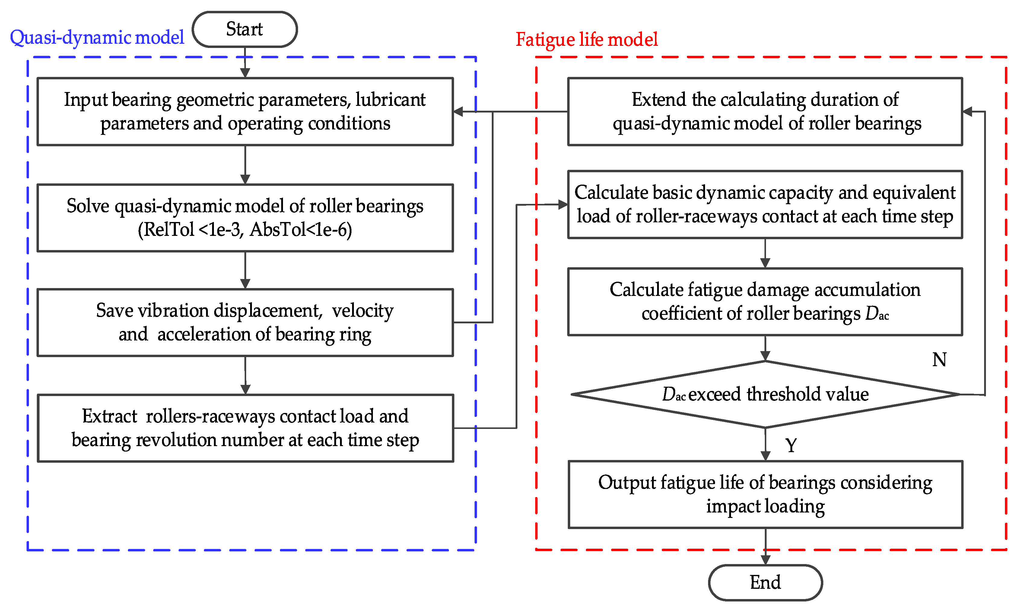
The evaluation procedure for the fatigue life of roller bearings considering impact loading is illustrated in Figure 2. The first step involves specifying the key model parameters, including bearing dimensions, material properties, and operating conditions. The quasi-dynamic model of roller bearing, as expressed in Equation (1), is solved using the Runge–Kutta method to determine the vibration displacement, velocity, and acceleration of the inner ring. From this analysis, the instantaneous fluctuations in contact loads between rollers and raceways, as well as the bearing’s revolution number at each time step, can be extracted. These parameters are then applied to the fatigue life model to compute the basic dynamic capacity and the equivalent loads for the roller–raceway contacts at each time step. Finally, the fatigue damage accumulation coefficient of the bearing under the specified operating conditions is calculated. The duration of the quasi-dynamic model calculations is gradually extended until the fatigue damage accumulation coefficient reaches its threshold value.

3. Results and Discussion

Taking TRB 32008 as an example, the fatigue life of roller bearings considering impact loading is analyzed and discussed in this section. The geometric and lubricant parameters of TRB 32008 are given in Table 1.

3.1. Comparison Analysis and Model Validation

To validate the correctness of the constructed models, their results are theoretically analyzed and compared with classical models. The roller bearing is modeled under a driving speed of 2000 rpm and a steady axial load of 3000 N. Since mechanical system components do not undergo overall plastic deformation during normal service, it is assumed that the impact loading on roller bearings caused by operating conditions is rigid impact, and a rectangular wave is used to characterize the impact loading process as illustrated in Figure 3. The frequency of the impact loading is 1 Hz with the peak value of 3000 N and the duration of 0.2 s.
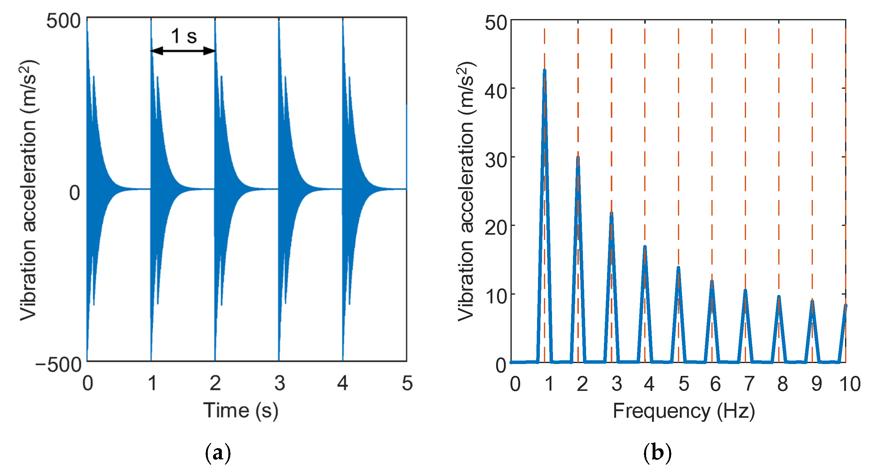
The vibration acceleration of the inner ring in the direction of impact loading is presented in Figure 4, which is calculated using the constructed quasi-dynamic model. As shown in Figure 4a, the vibration acceleration signal exhibits periodic impact responses at 1 s intervals, and the impact response will gradually decay due to the oil film damping. Furthermore, Figure 4b demonstrates that the vibration response frequency of the inner ring is a multiple of the impact loading frequency.
Taking the maximum contact load between rollers and outer raceway as an example, the characteristics of instantaneous fluctuations in contact loads are shown in Figure 5. The results indicate that the average contact load obtained by the constructed quasi-dynamic model agrees well with Harris’s static model [33], both at the impact loading peak duration and the steady loads duration. The above analyses and comparison show that the constructed quasi-dynamic model can accurately characterize the influences of impact loading on the instantaneous fluctuations in contact load.
Even if only steady loads are applied to the bearing, the contact load between rollers and raceways also fluctuates slightly due to the time-varying position angle of rollers. Compared to the static model, the constructed quasi-dynamic model is able to extract the above slight fluctuations in contact load and take them into the fatigue life model of the roller bearing. Figure 6 presents the roller–outer raceway maximum contact load obtained by the constructed quasi-dynamic model and that of Harris’s static model, in which the roller bearing is modeled under the steady axial load of 3000 N and the driving speed of 2000 rpm. The above phenomena indicate that the constructed quasi-dynamics model of roller bearing can characterize the impact loads excitation and its influence on the instantaneous fluctuations in contact load between rollers and raceways.
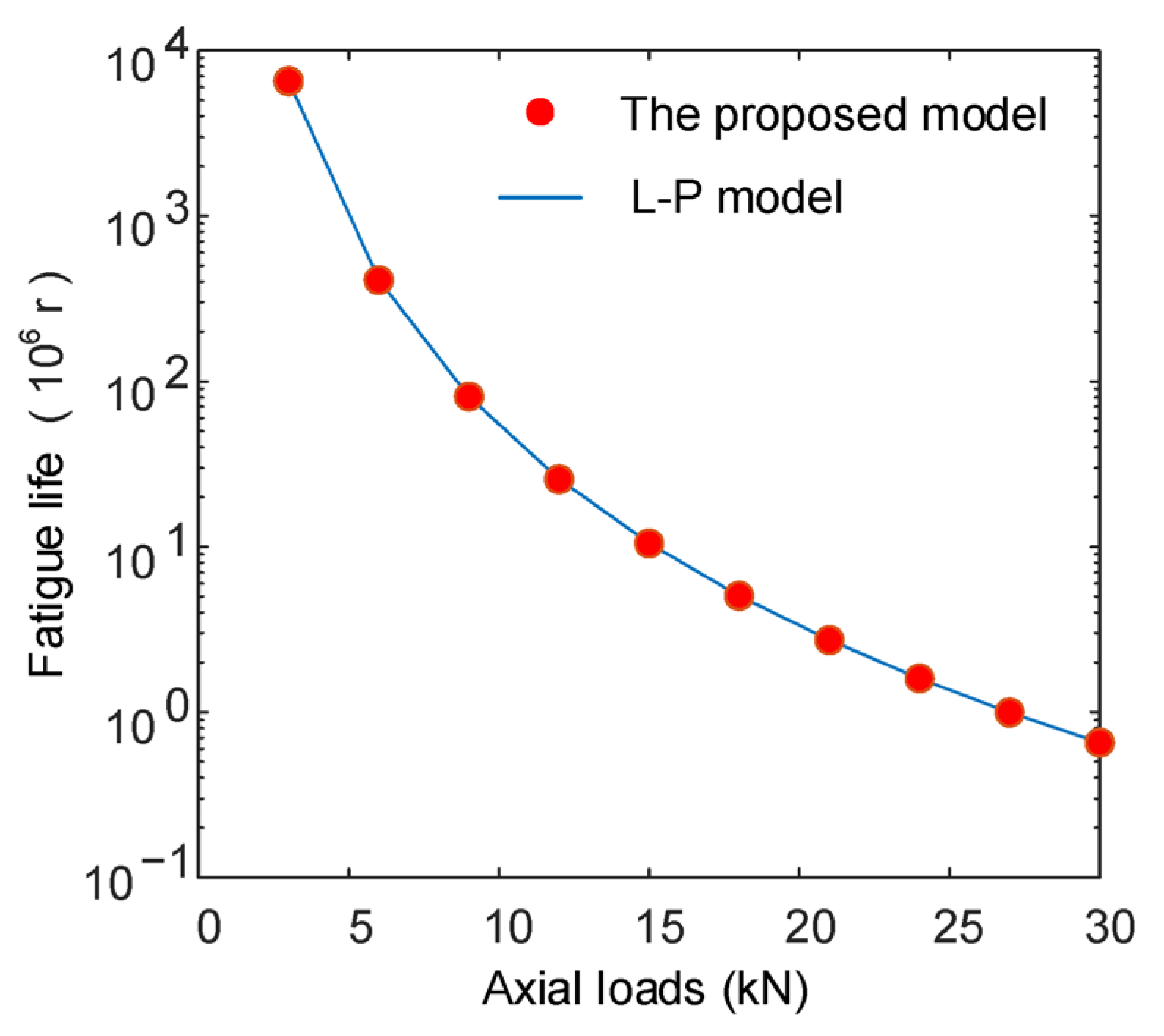
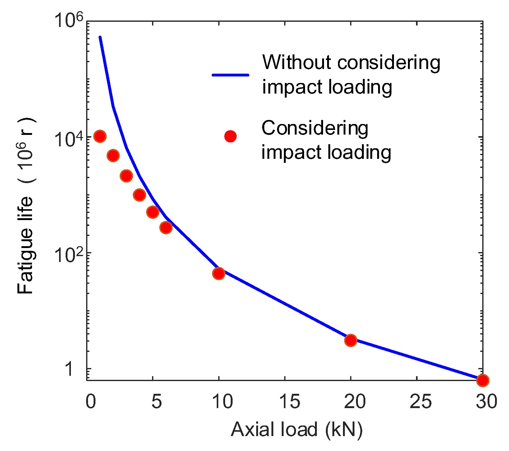
Based on the contact loads between rollers and raceways obtained by the quasi-dynamic model of roller bearings, the fatigue life of roller bearings is predicted using the constructed fatigue life model in this paper. The comparison of fatigue life predicted by the different models is shown in Figure 7. As shown in Figure 7, the results of the fatigue life model constructed in this paper align closely with those of the L-P model under conditions of different axial loads. The results verify the validity of the constructed fatigue life model, and also indicate that the slight fluctuation in contact loads caused by the time-varying position angle of rollers can be ignored in the fatigue life prediction of roller bearings, which is consistent with the previous engineering experiences.

3.2. Instantaneous Fluctuation in Contact Load Considering Impact Loading

In this section, the instantaneous fluctuation in maximum contact load between rollers and raceways caused by the impact loading under various bearing speeds and steady loads is analyzed, where the impact loading frequency is 1 Hz and the impact loading duration is 0.2 s. Since the characteristic of contact load fluctuation between each roller and raceway is essentially the same, this section only presents the maximum contact load between a roller and outer raceway to illustrate the characteristic of instantaneous fluctuation in contact load caused by the impact loading.
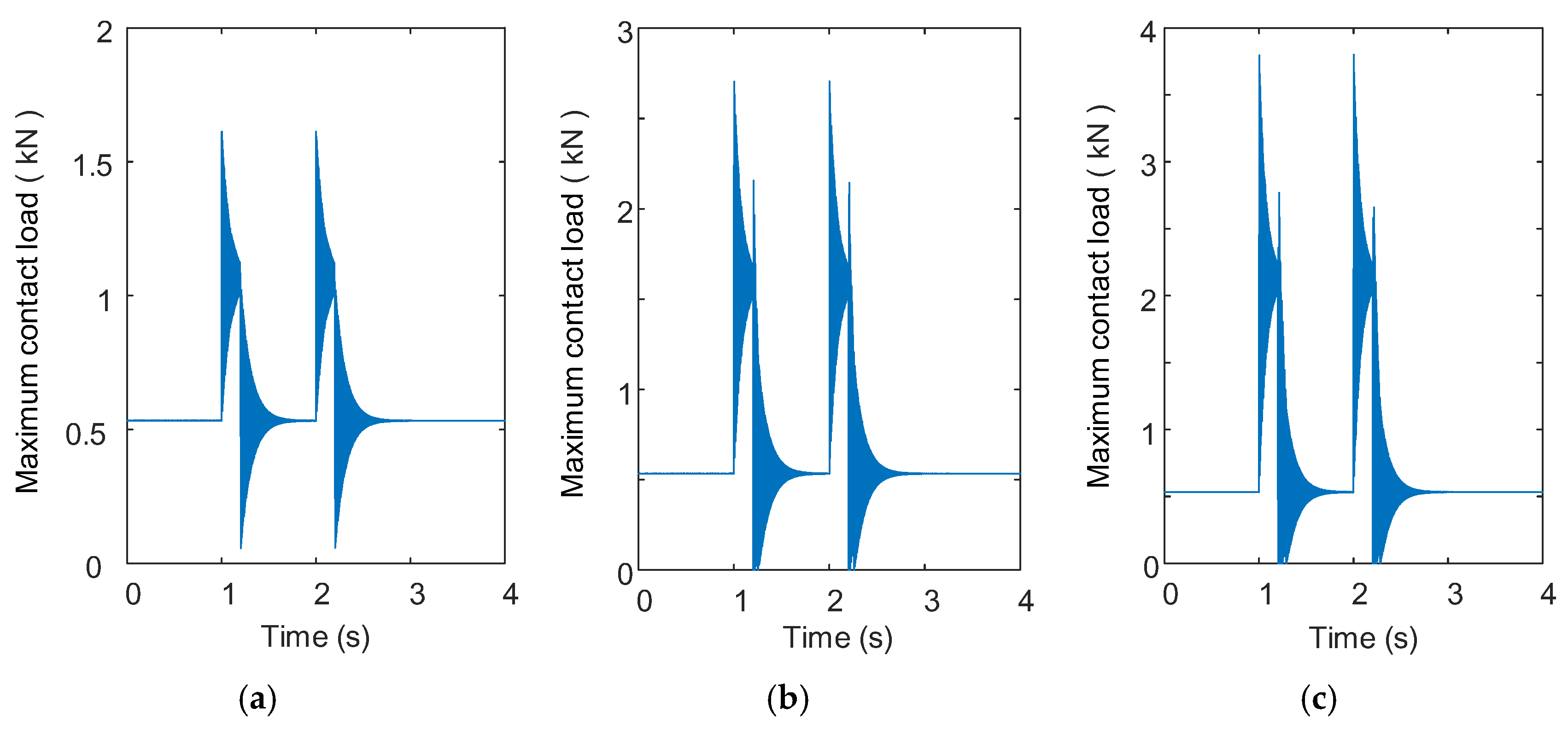
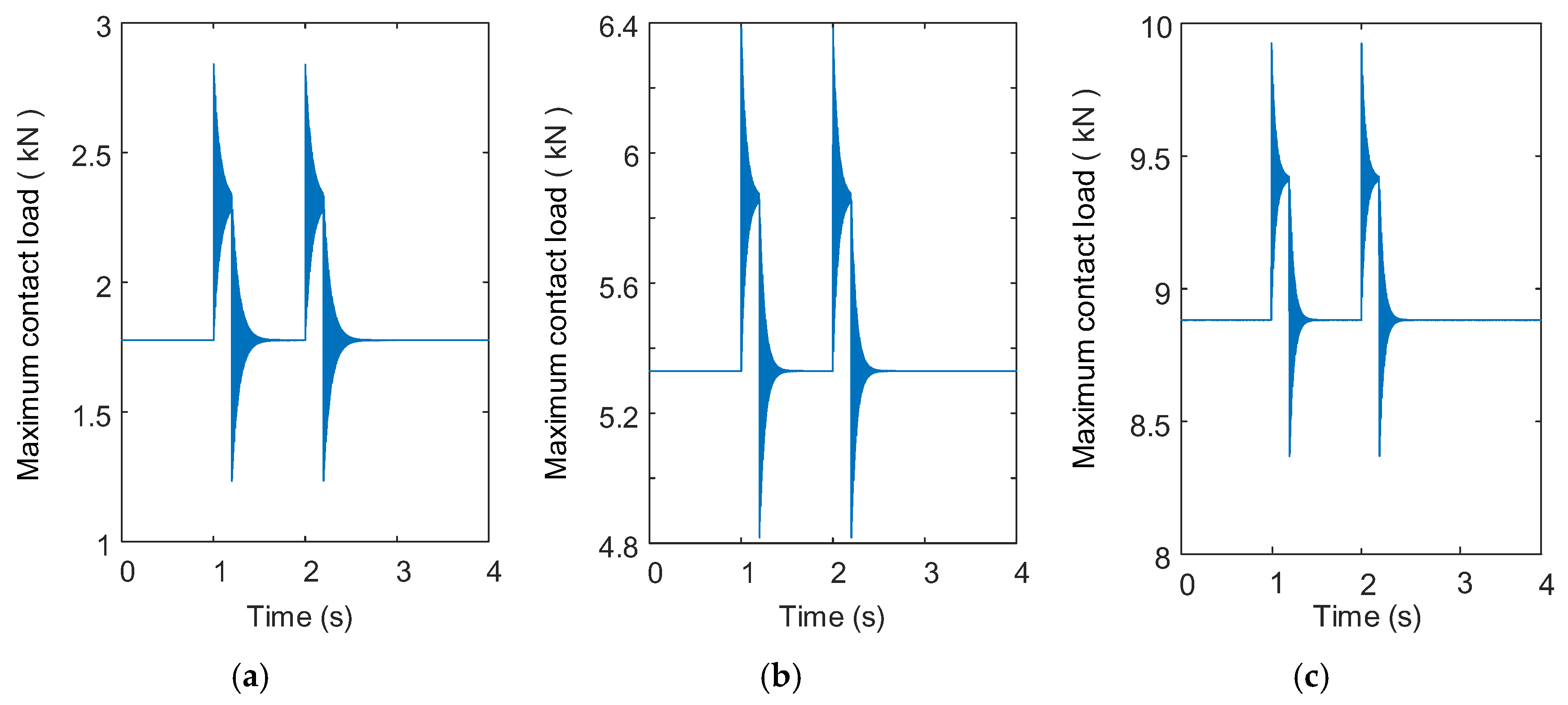
Figure 8 presents the maximum contact load between the rollers and the outer raceway at a speed of 2000 rpm, a steady axial load of 3000 N, and impact loading with a peak ranging from 3000 N to 9000 N. As the peak of impact loading increases, the fluctuation range of the maximum contact load grows significantly, while the fluctuation duration remains nearly constant. When the peak of impact loading substantially exceeds the steady loads, the roller bearing may briefly experience unloading, as illustrated in Figure 8b,c, where the maximum contact load drops to 0 N. Therefore, for certain impact loading, applying sufficient bearing preload (steady axial load) is essential to prevent a sudden unloading and corresponding sudden loss of bearing support stiffness.
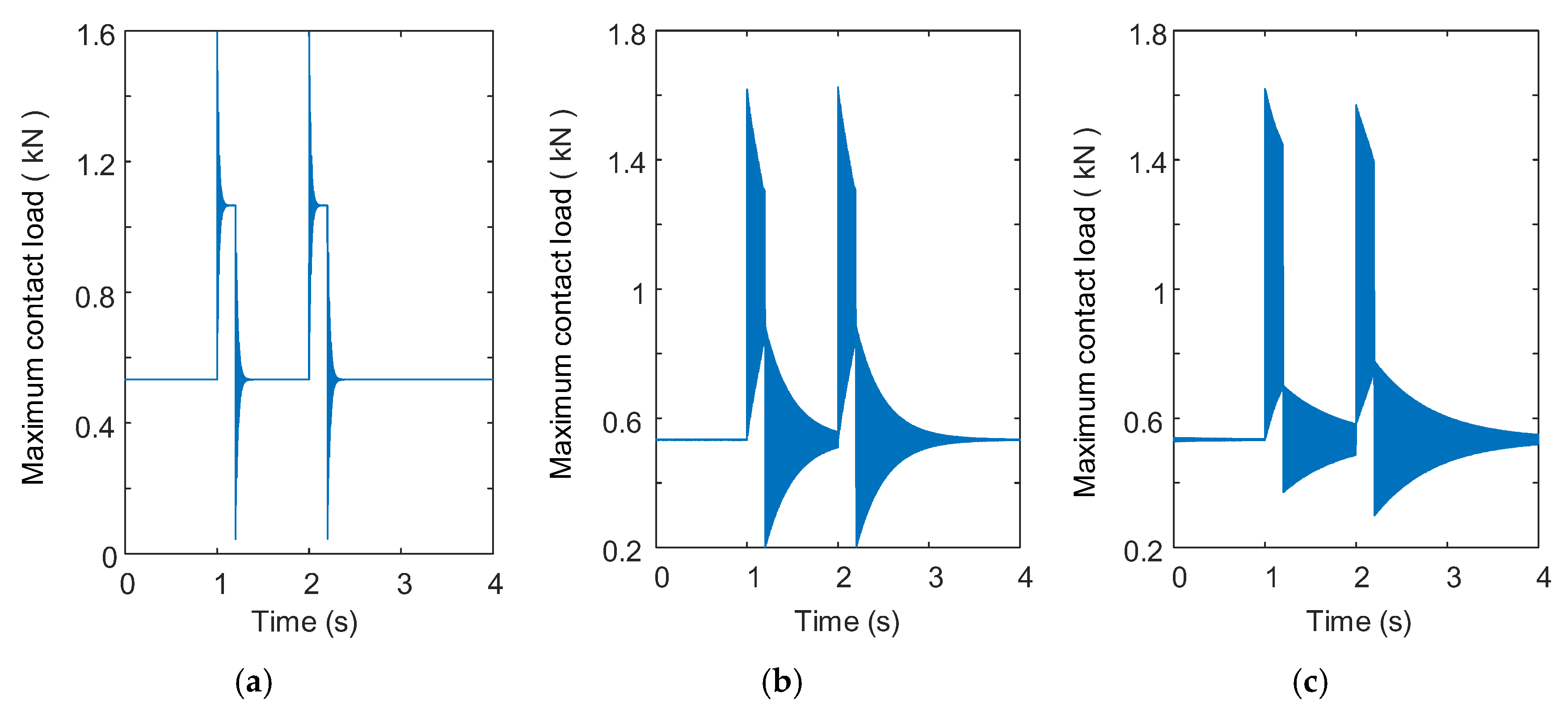
Figure 9 presents the maximum contact load between the rollers and the outer raceway at a speed of 2000 rpm, impact loading with a peak value of 9000 N, and a steady axial load ranging from 10,000 N to 50,000 N. As the steady axial load increases, the fluctuation duration of the maximum contact load decreases gradually. The above contact load fluctuation phenomenon is due to the fact that the increase in steady axial load reduces the lubricant film thickness between rollers and raceways, which increases the oil film damping between rollers and raceways as well as the integrated damping of roller bearings. However, there is no significant change in the fluctuation range of the maximum contact load under different steady axial loads.
Figure 10 presents the maximum contact load between the rollers and the outer raceway at the steady axial load of 3000 N, the impact load with a peak value of 3000 N, and a bearing speed ranging from 500 rpm to 10,000 rpm. With an increase in bearing speed, the duration of maximum contact load fluctuations increases significantly, accompanied by noticeable changes in the fluctuation pattern. The above contact load fluctuation phenomenon is due to the increase in bearing speed, which increases the lubricant film thickness between rollers and raceways, which in turn significantly decreases the oil damping between rollers and raceways and as well as the integrated damping of roller bearings. When the bearing speed exceeds a certain threshold, the integrated damping of the bearings becomes insufficient to flatten the contact load fluctuations between two impact loading intervals, ultimately resulting in the superposition of impact loading responses.

3.3. Fatigue Life of Roller Bearings Considering Impact Loading

In this section, the influence of impact loading on fatigue life of roller bearings under various bearing speeds and steady loads is discussed based on the instantaneous fluctuations in contact load.
Figure 11 presents the influence of impact loading on fatigue life of the roller bearing at the bearing speed of 2000 rpm and the steady axial load ranging from 1000 N to 30,000 N, where the impact loading peak is 3000 N, the impact loading frequency is 1 Hz, and the impact loading duration is 0.2 s. As shown in Figure 11, when the steady axial load is 1000 N, the impact loading reduces the fatigue life of roller bearings by 98.1%. However, when the steady axial load is increased to 30,000 N, the impact loading causes the fatigue life of the roller bearing to be only 4.6%. From the results in Figure 11, two conclusions can be drawn: (1) the presence of frequent impact loading will lead to a decrease in the fatigue life of roller bearings; (2) as the ratio of the peak of impact loading to the steady loads decreases, the influence of the impact loading on bearing life diminishes.
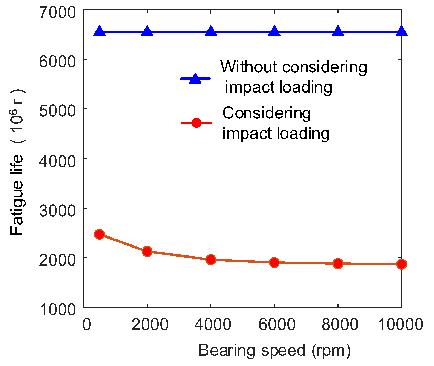
Figure 12 presents the influence of impact load on fatigue life of the roller bearing at the steady axial load of 3000 N and the bearing speed ranging from 500 rpm to 10,000 rpm, where the impact loading peak is 3000 N, the impact loading frequency is 1 Hz, and the impact loading duration is 0.2 s. As shown in Figure 12, when the bearing speed is 500 rpm, the impact loading reduces the fatigue life of roller bearings by 62.3%. When the bearing speed is 10,000 rpm, the impact loading causes the fatigue life of the roller bearing to be 71.5%. One can find that the influence of bearing speed on the fatigue life of roller bearings is negligible without considering impact loading, which is consistent with the results of the classical L-P model and the bearing bench experiments. However, when the impact loading is considered, the fatigue life of roller bearings decrease is more significant as the increase of bearing speed. This trend continues until the bearing speed exceeds a certain threshold, beyond which the degree of bearing life reduction stabilizes.
The above phenomenon is due to the fact that the bearing speed and loads directly determine the lubricant film thickness between rollers and raceways, and then affect the instantaneous fluctuation in contact load as well as the fatigue life of roller bearings under impact loading. Thus, accurately evaluating the fatigue life of roller bearings under impact loading requires specifying the impact loading parameters, the bearing speed, and steady loads.
It should be noted that when the amplitude of the impact loading is too large, causing plastic deformation in the roller–raceway contact area, namely the equivalent load of bearing exceeding the rated static load of bearing, the model constructed in this paper will not be able to accurately assess the bearing’s service life. In addition, in order to obtain more accurate assessment results, the waveforms and duration parameters of impact loading acting on rolling bearings in different mechanical systems can be set according to the structural characteristics and operating conditions of the mechanical systems.

4. Conclusions

In this paper, a numerical framework for predicting fatigue life of roller bearings considering impact loading is constructed. A quasi-dynamic model of roller bearings is established to capture the instantaneous fluctuation in contact load between rollers and raceways caused by the impact loading. Based on the fatigue damage accumulation theory and a series of ISO standards for bearing fatigue life, a fatigue life model of roller bearings is established to accurately characterize the fatigue life of roller bearings under the condition of instantaneous fluctuations in contact loads. On this basis, the influence of the impact loading on fatigue life of roller bearings under various speeds and steady loads is analyzed. From the results, the following conclusions have been obtained.
The instantaneous fluctuation range in contact loads between rollers and raceways is mainly determined by the amplitude of impact loading. However, the duration and the fluctuation pattern in contact loads between rollers and raceways are determined by both impact loading, steady loads, and bearing speed. The above instantaneous fluctuations in contact loads will further significantly affect the fatigue life of roller bearings. When the steady-state load and the impact load amplitude are of the same magnitude, frequent impact loads will reduce the fatigue life of rolling bearings by more than 90%. As bearing speed increases, the reduction in fatigue life caused by impact loading becomes more significant. This trend continues until the bearing speed exceeds a certain threshold, beyond which the degree of bearing life reduction stabilizes.
To accurately predict the fatigue life of roller bearings under real operating conditions, it is necessary to account for the influence of impact loading on the instantaneous fluctuation in roller–raceway contact load, especially for high speeds and light steady load conditions.

Author Contributions

Y.L. (Yuwei Liu): writing—original draft, formal analysis, investigation, methodology, funding acquisition, and supervision. H.G.: validation and writing—review and editing. Y.L. (Yufei Li): software and visualization. Z.G.: writing—review and editing and funding acquisition. T.Z.: writing—review and editing and project administration. All authors have read and agreed to the published version of the manuscript.

Funding

This research was funded by the National Natural Science Foundation of China (Grant Number: 52205282), Shaanxi Provincial Department of Education Special Science Fund (Grant Number: 22JK0469), and General Projects of Key Industrial Chains in Shaanxi Province (Grant Number: 2023-ZDLNY-68).

Data Availability Statement

Dataset is available upon request from the authors.

Conflicts of Interest

The authors declare no conflicts of interest.

Nomenclature

The following nomenclature is used in this manuscript:
cOil film damping factor between roller and raceways (N·s/m)
cx, cy, czIntegrated damping of bearing (N·s/m)
dmPitch diameter of bearing (m)
DMean diameter of roller (m)
DacFatigue damage accumulation coefficient (1)
EEquivalent elastic modulus between roller and raceway (N/m2)
FdjoOil film damping force between jth roller and outer ring (N)
Fx, Fy, FzExternal loads acting on bearing (N)
hcCenter oil film thickness between roller and raceway (m)
kx, ky, kzIntegrated stiffness of bearing (N/mm)
KContact stiffness factor between roller and raceways (N/mm10/9)
LkPotential fatigue life corresponding to the roller–raceways contact load in kth time step (r)
Lo, LiRoller and outer raceway contact fatigue life (r)
LiRoller and inner raceway contact fatigue life (r)
mQuality of inner ring (kg)
nBearing speed (r/min)
nkBearing speed in kth time step (r/min)
nrNumber of rollers inside bearing (1)
QcBasic dynamic capacity for roller–raceway contact (N)
QeEquivalent load for roller–raceway contact (N)
QeiEquivalent load for roller–inner raceway contact (N)
QeoEquivalent load for roller–outer raceway contact (N)
QjiContact load between jth roller and inner raceway (N)
QjoContact load between jth roller and outer ring (N)
REquivalent curvature radius between roller and raceway (m)
uEntrainment velocity between roller and raceway (m/s)
uiEntrainment velocity between roller and inner raceway (m/s)
uoEntrainment velocity between roller and outer raceway (m/s)
vjoNormal oil film extrusion speed between jth roller and outer raceway (m/s)
wContact load per unit length between roller and raceway (N/m)
x, y, zDisplacement of inner ring (m)
x ˙ ,   y ˙ ,   z ˙ Velocity of inner ring (m/s)
x ¨ ,   y ¨ ,   z ¨ Acceleration of inner rings (m/s2)
αMean contact angle between roller and raceways (rad)
αiRoller–inner raceway contact angle (rad)
αoRoller–outer raceway contact angle (rad)
α0Pressure–viscosity coefficient of the lubricant (m2/N)
γGeometry coefficients (1)
δjoElastic deformation between jth roller and outer raceway (mm)
ΔtTime step size (s)
η0Lubricant viscosity in atmospheric conditions (Pa·s)
λReduction factor for basic dynamic capacity (1)
φjAngular position of jth roller after running time t (rad)
φj0Initial angular position of jth roller (rad)

References

  1. Lundberg, G.; Palmgren, A. Dynamic capacity of rolling bearings. J. Appl. Mech. 1949, 16, 165–172. [Google Scholar] [CrossRef]
  2. Chiu, Y.P.; Tallian, T.E.; McCool, J.I. An engineering model of spalling fatigue failure in rolling contact: I. The subsurface model. Wear 1971, 17, 433–446. [Google Scholar] [CrossRef]
  3. Tallian, T. Weibull distribution of rolling contact fatigue life and deviations therefrom. A S L E Trans. 1962, 5, 183–196. [Google Scholar] [CrossRef]
  4. Ioannides, E.; Harris, T.A. A new fatigue life model for rolling bearings. J. Tribol. 1985, 107, 367–377. [Google Scholar] [CrossRef]
  5. Harris, T.A.; Mccool, J.I. On the accuracy of rolling bearing fatigue life prediction. J. Tribol. 1996, 118, 297–309. [Google Scholar] [CrossRef]
  6. ANSI/ABMA 9-2020; Load Ratings and Fatigue Life for Ball Bearings. American National Standards Institute (ANSI)/American Bearing Manufacturers Association (ABMA): New York, NY, USA, 2020.
  7. ANSI/ABMA 11-2020; Load Ratings and Fatigue Life for Roller Bearings. American National Standards Institute (ANSI)/American Bearing Manufacturers Association (ABMA): New York, NY, USA, 2020.
  8. ISO/TR 1281-1:2008; Rolling Bearings—Explanatory Notes on ISO 281—Part 1: Basic Dynamic Load Rating and Basic Rating Life. International Organization for Standardization (ISO): Geneva, Switzerland, 2008.
  9. ISO/TS 16281:2008; Rolling Bearings—Methods for Calculating the Modified Reference Rating Life for Universally Loaded Bearings. International Organization for Standardization (ISO): Geneva, Switzerland, 2008.
  10. ISO 281:2007; Rolling Bearings—Dynamic Load Ratings and Rating Life. International Organization for Standardization (ISO): Geneva, Switzerland, 2007.
  11. Oswald, F.B.; Zaretsky, E.V.; Poplawski, J.V. Effect of internal clearance on load distribution and life of radially loaded ball and roller bearings. Tribol. Trans. 2012, 55, 245–265. [Google Scholar] [CrossRef]
  12. Takahashi, K.; Nagatomo, T. Effects of axial clearance on surface initiated flaking in tapered roller bearings. J. Tribol. 2023, 145, 054301. [Google Scholar] [CrossRef]
  13. Fang, B.; Zhang, J. Analytical determination of the optimal clearance for the fatigue life of ball bearing under different load conditions. J. Tribol. 2022, 144, 021203. [Google Scholar] [CrossRef]
  14. Tong, V.C.; Hong, S.W. Fatigue life of tapered roller bearing subject to angular misalignment. Proc. Inst. Mech. Eng. Part C J. Mech. Eng. Sci. 2016, 230, 147–158. [Google Scholar] [CrossRef]
  15. Tong, V.C.; Hong, S.W. Analysis of the stiffness and fatigue life of double-row angular contact ball bearings. J. Korean Soc. Precis. Eng. 2017, 34, 813–821. [Google Scholar] [CrossRef]
  16. Zhang, Y.; Zhang, M.; Wang, Y.; Xie, L. Fatigue life analysis of ball bearings and a shaft system considering the combined bearing preload and angular misalignment. Appl. Sci. 2020, 10, 2750. [Google Scholar] [CrossRef]
  17. Zhang, J.; Fang, B.; Hong, J.; Zhu, Y. Effect of preload on ball-raceway contact state and fatigue life of angular contact ball bearing. Tribol. Int. 2017, 114, 365–372. [Google Scholar] [CrossRef]
  18. Jiang, Y.; Zhu, T.; Deng, S. Combined analysis of stiffness and fatigue life of deep groove ball bearings under interference fits, preloads and tilting moments. J. Mech. Sci. Technol. 2023, 37, 539–553. [Google Scholar] [CrossRef]
  19. Morales-Espejel, G.E.; Gabelli, A. A model for rolling bearing life with surface and subsurface survival: Surface thermal effects. Wear 2020, 460, 203446. [Google Scholar] [CrossRef]
  20. Kim, T.; Suh, J.; Lee, J.; Lee, B.; Yu, Y. Fatigue life prediction of double-row tapered roller bearings considering thermal effect. Adv. Mech. Eng. 2023, 15, 16878132231154099. [Google Scholar] [CrossRef]
  21. Zaretsky, E.V. Rolling Bearing Life Prediction, Theory, and Application. US Patent 1234567B1, 27 August 2020. [Google Scholar]
  22. Lee, J.G.; Palazzolo, A. Catcher bearing life prediction using a rainflow counting approach. J. Tribol. 2012, 134, 031101. [Google Scholar] [CrossRef]
  23. Yu, A.; Huang, H.; Li, Y.; Yang, W.; Deng, Z. A modified nonlinear fatigue damage accumulation model for life prediction of rolling bearing under variable loading conditions. Fatigue Fract. Eng. Mater. Struct. 2022, 45, 852–864. [Google Scholar] [CrossRef]
  24. Cui, L. A new fatigue damage accumulation rating life model of ball bearings under vibration load. Ind. Lubr. Tribol. 2020, 72, 1205–1215. [Google Scholar] [CrossRef]
  25. Lei, Y.; Han, D.; Lin, J.; He, Z. Planetary gearbox fault diagnosis using an adaptive stochastic resonance method. Mech. Syst. Signal Process. 2013, 38, 113–124. [Google Scholar] [CrossRef]
  26. Zhou, J.; Sun, W.; Yuan, L. Nonlinear vibroimpact characteristics of a planetary gear transmission system. Shock. Vib. 2016, 1, 4304525. [Google Scholar] [CrossRef]
  27. Li, X.; Gong, F.; Tao, M.; Dong, L.; Du, K.; Ma, C.; Zhou, Z.; Yin, T. Failure mechanism and coupled static-dynamic loading theory in deep hard rock mining: A review. J. Rock Mech. Geotech. Eng. 2017, 9, 767–782. [Google Scholar] [CrossRef]
  28. Bian, J.; Gu, Y.; Murray, M.H. A dynamic wheel–rail impact analysis of railway track under wheel flat by finite element analysis. Veh. Syst. Dyn. 2013, 51, 784–797. [Google Scholar] [CrossRef]
  29. Kwofie, S.; Rahbar, N. A fatigue driving stress approach to damage and life prediction under variable amplitude loading. Int. J. Damage Mech. 2013, 22, 393–404. [Google Scholar] [CrossRef]
  30. Harris, T.A. Essential Concepts of Bearing Technology, 5th ed.; Taylor & Francis: New York, NY, USA, 2008; pp. 134–136, 213–223. [Google Scholar]
  31. Dowson, D.; Higginson, G.R.; Nielsen, K.W. Elasto-hydrodynamic lubrication (International series in material, science and technology). J. Tribol. 1978, 100, 447. [Google Scholar] [CrossRef]
  32. Wen, S. Elastohydrodynamic Lubrication; Tsinghua University Press: Beijing, China, 1992; pp. 122–126. [Google Scholar]
  33. Harris, T.A. Advanced Concepts of Bearing Technology, 5th ed.; Taylor & Francis: New York, NY, USA, 2008; pp. 16–18. [Google Scholar]
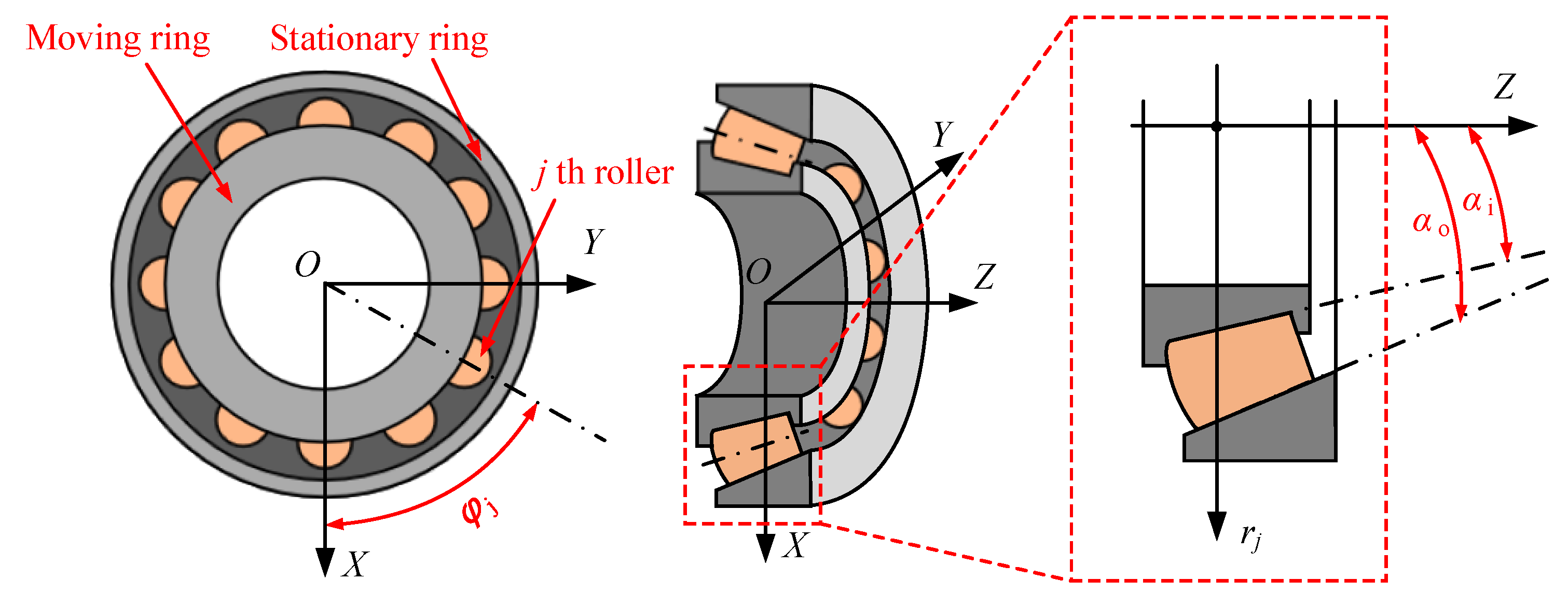
Figure 1. The structural schematic diagram of TRBs.
Processes 13 02545 g001
Figure 2. Evaluation procedure of the fatigue life of roller bearings considering impact loading.
Processes 13 02545 g002
Figure 3. Schematic diagram of impact loading.
Processes 13 02545 g003
Figure 4. The vibration acceleration of bearing inner ring considering impact loading: (a) time domain signal; (b) envelope spectrum signal.
Processes 13 02545 g004
Figure 5. The comparison results of roller–raceway contact load between the constructed quasi-dynamic model and Harris’s static model.
Processes 13 02545 g005
Figure 6. Slight fluctuation in maximum contact load under steady axial loads.
Processes 13 02545 g006
Figure 7. The comparison curves of fatigue life between the constructed model and L-P model.
Processes 13 02545 g007
Figure 8. The maximum contact load under various impact loading peaks: (a) impact loading peak is 3000 N; (b) impact loading peak is 6000 N; (c) impact loading peak is 9000 N.
Processes 13 02545 g008
Figure 9. The maximum contact load under various steady loads: (a) steady axial load is 10,000 N; (b) steady axial load is 30,000 N; (c) steady axial load is 50,000 N.
Processes 13 02545 g009
Figure 10. The maximum contact load under various bearing speeds: (a) bearing speed is 500 rpm; (b) bearing speed is 5000 rpm; (c) bearing speed is 10,000 rpm.
Processes 13 02545 g010
Figure 11. The influence of impact loading on fatigue life of roller bearings under various axial steady loads.
Processes 13 02545 g011
Figure 12. The influence of impact loading on fatigue life of roller bearings under various bearing speeds.
Processes 13 02545 g012
Table 1. The geometric and lubricant parameters.
Geometrical ParametersValue
Mean diameter of taper roller (m)6.49 × 10⁻³
Pitch diameter of bearing (m)0.1872
Effective length of roller (m)1.366 × 10⁻²
Number of rollers23
Contact angle between roller and outer raceway (rad)0.245
Contact angle between roller and inner raceway (rad)0.195
Contact angle between roller and flange (rad)1.562
Taper angle of roller (rad)0.026
Lubricant ParametersValue
Viscosity in atmospheric conditions (Pa·s)3.7 × 10⁻²
Pressure–viscosity coefficient (m2/N)2.2 × 10−8
Disclaimer/Publisher’s Note: The statements, opinions and data contained in all publications are solely those of the individual author(s) and contributor(s) and not of MDPI and/or the editor(s). MDPI and/or the editor(s) disclaim responsibility for any injury to people or property resulting from any ideas, methods, instructions or products referred to in the content.