1. Introduction
During late-stage oilfield development, annular channeling issues—triggered by compromised cementing quality or stimulation treatments (e.g., fracturing, acidizing, and thermal recovery operations)—become increasingly prevalent, particularly at the primary cementing interface (cement-formation boundary) and secondary cementing interface (cement-casing boundary) [
1,
2]. Channeling directly connects high-pressure water zones with low-pressure oil/gas layers or the wellbore, disrupting original development sequences, triggering violent water flooding in oil wells, and severely reducing crude oil recovery [
3,
4,
5,
6]. Especially for typical reservoirs like Jianghan Oilfield with high temperature (≈100 °C), high salinity (TDS > 3.0 × 10
5 mg/L), and low permeability (<50 mD), effectively plugging channeling pathways while maximizing protection of the reservoir matrix is a critical challenge for maintaining stable field production.
Current mainstream channeling plugging technologies primarily rely on agents such as cement slurry squeezing, thermosetting resins, gels, and foams [
7]. However, these materials have significant limitations: cement slurry, while low-cost and high-strength, easily causes permanent reservoir damage due to solid-phase invasion and lacks selectivity [
8,
9,
10,
11]; thermosetting resins exhibit excellent fluidity and ultimate strength but are costly, lack intrinsic oil–water selectivity, and carry risks of damaging oil zones during injection; gel plugging agents offer certain selectivity but generally have weak strength and limited temperature/salinity resistance (often degrading above 80–90 °C or in high-salinity environments), failing to meet long-term plugging requirements in high-temperature/high-salinity reservoirs; foam agents rely on the Jamin effect, showing poor long-term plugging effectiveness and instability for large channeling pathways, with performance also sensitive to temperature and salinity; clay or water-swellable particles are mainly suitable for matrix plugging but exhibit insufficient strength for fracture-type channeling, and their swelling can be inhibited by high salinity. Therefore, there is an urgent need to develop a novel plugging system that integrates high strength, superior intrinsic oil–water selectivity, high-temperature/high-salinity resistance, and precise action on channeling fractures while avoiding damage to the reservoir matrix.
Oil-soluble resin (OSR) particles demonstrate distinct advantages over these conventional technologies and show great potential for selective channeling plugging. OSR particles exhibit favorable inherent oil–water selectivity due to their solubility in oil phases and solid-state retention in aqueous phases [
12,
13,
14]. This unique property minimizes damage to oil-bearing zones (where particles can dissolve or be easily backflushed) while enabling effective water flow blockage in water channels. Crucially, OSR possesses inherent high mechanical strength and exceptional temperature/salinity tolerance, enabling it to withstand harsh reservoir conditions (≈100 °C, TDS > 3.0 × 10
5 mg/L) and form durable plugs [
11,
12,
13], overcoming the key weakness of gels. Furthermore, the risk of permanent reservoir damage is significantly lower compared to cement slurries, as potential damage from fine particles can be mitigated through optimized particle size control and is often reversible in oil zones due to solubility.
However, their application in water shutoff/channeling plugging is limited. Conventional OSR particles have a large size and high hardness, making it difficult for them to deform through small reservoir pore throats for effective deep-fracture packing [
15]. Although some studies attempt to inject OSR in a viscous state above its softening point for water shutoff, this completely sacrifices its high-strength advantage as solid particles. Research indicates that solid OSR particles primarily form filter cake blockages near the wellbore, suitable for scenarios requiring forward wellbore-formation pressure bearing (e.g., drilling loss control), but plugging channeling (requiring reverse wellbore-formation pressure bearing) demands that the agent enter deep into water-channeling pathways and form a firm, durable packing plug [
16,
17].
This study proposes an innovative strategy: drawing on the successful mechanism of curable rapid fluid-loss lost circulation materials (e.g., Diaseal M) in controlling severe drilling losses [
18,
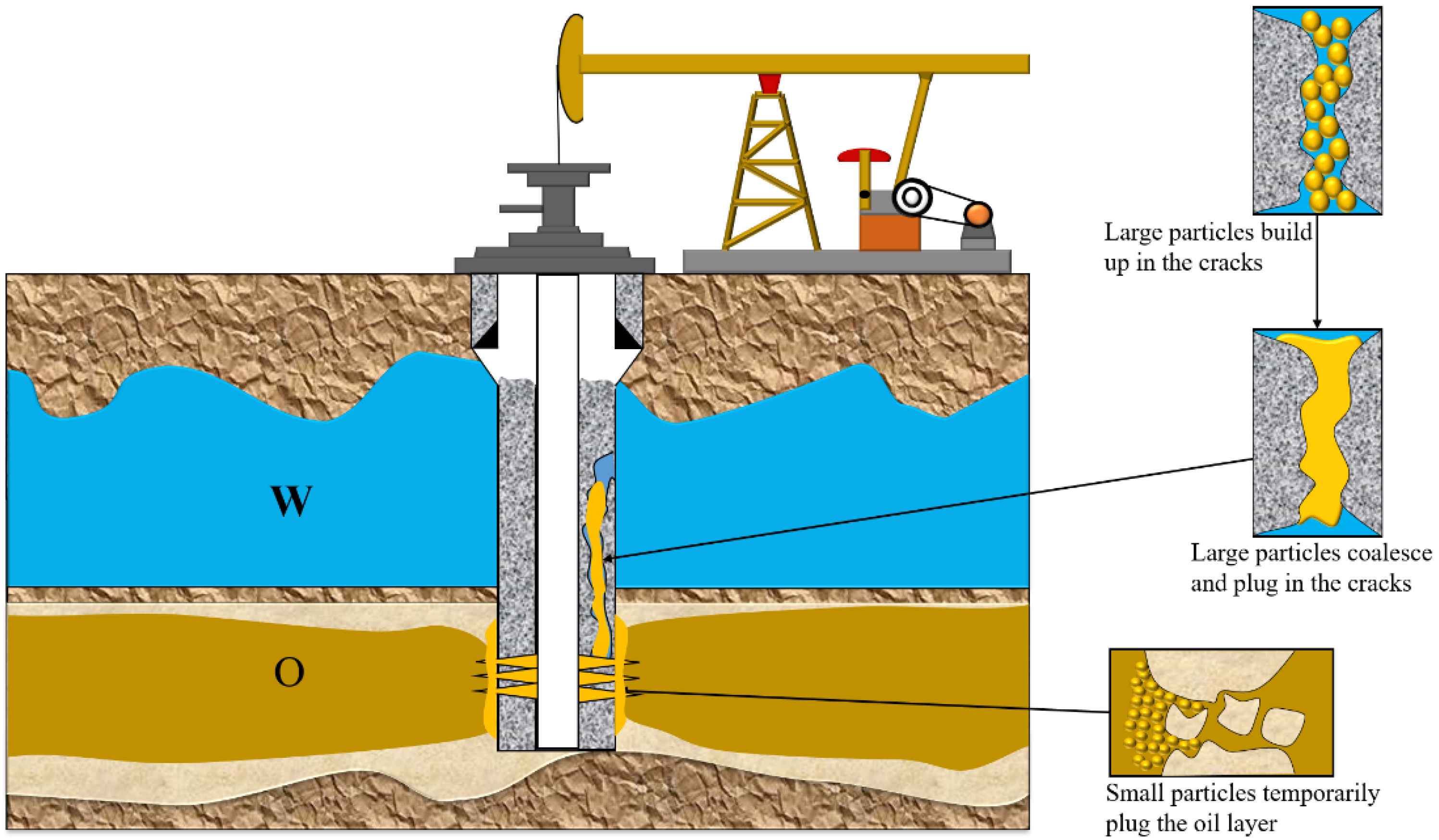
19], we apply it to the OSR particle system to overcome the deep placement challenge and leverage its inherent strengths, thereby achieving high-strength selective plugging of channeling fractures. The core mechanism is as follows: under injection differential pressure, free water in the agent suspension rapidly filtrates into the formation matrix, while solid-phase OSR particles concentrate and bridge/accumulate within channeling fractures to form an initial high-permeability filter cake; subsequently, at reservoir temperature, OSR particles utilize their thermoviscoelasticity to coalesce, melt, and ultimately solidify into a dense, high-strength monolithic plug. This strategy is expected to simultaneously achieve precise deep-fracture plugging, high strength, superior oil–water selectivity (particles non-damaging to oil zones; plug blocking water flow), and in situ solidification triggered by formation thermal energy while minimizing reservoir damage.
The critical challenge in realizing this goal is precise control of OSR particle packing behavior within fractures. Particle size and gradation are core factors determining bridging efficiency, packing structure, filter cake permeability, and ultimate plug strength.
Based on the mechanism of curable rapid fluid-loss lost circulation, this study aims to achieve tight packing and solidification of OSR particles into a high-strength plug within channeling fractures. It investigates the impact of particle size and sorting on their injectivity and plugging performance to demonstrate the feasibility of utilizing OSR particles for high-strength selective water shutoff in channeling fractures, fully capitalizing on their unique advantages.
3. Experimental Method
Dynamic Thermomechanical Analysis. The OSR particles were heated to 200 °C in a flowing state and poured into a mold with a length of 60 mm, a width of 10 mm, and a thickness of 4 mm; the resin was cooled to room temperature to prepare a sample of the size required for measurement. The thermomechanical properties of the specimen were tested using a dynamic thermomechanical analyzer with a double cantilever grip set at a frequency of 1 Hz, an amplitude set to 0.01%, a temperature increase from 25 °C to 200 °C, and a heating rate of 2 °C/min.
Viscosity Testing. The apparent viscosity of the sample was measured at 100 rpm using a six-speed rotational viscometer. This rotational speed corresponds to a shear rate of 170.3 s−1, equivalent to the shear rate at the injection point under field operational conditions. The dial reading obtained at 100 rpm was subsequently converted to apparent viscosity using the standard conversion formula.
Preparation and particle size testing of OSR particles. The OSR bulk particles were crushed with a pulverizer to obtain a powdered particle sample, and the OSR sample was combined with 1% DTAC dispersant to prepare a pure water or simulated water suspension with an OSR content of 10% for later use. The suspension was diluted with pure water and ultrasonically dispersed for particle size testing. The volume cumulative distribution curve and frequency distribution curve were obtained, where
DN was the average particle size when the volume cumulative distribution reached N%, and the sorting coefficient
S0 was calculated as follows (1):
Scanning Electron Microscopy. A pure water suspension was prepared with crushed OSR particles and diluted with pure water until it was almost transparent. After ultrasonic dispersion to make it uniform, a little liquid sample was dropped on a silicon wafer and dried. Then, field emission scanning electron microscopy was used for measurement. The acceleration voltage was 5 kV. The test mode was the secondary electron mode. The working distance and magnification were adjusted according to the test situation. We observed the microscopic morphology of the OSR particles at room temperature and after heating at 100 °C for 6 h.
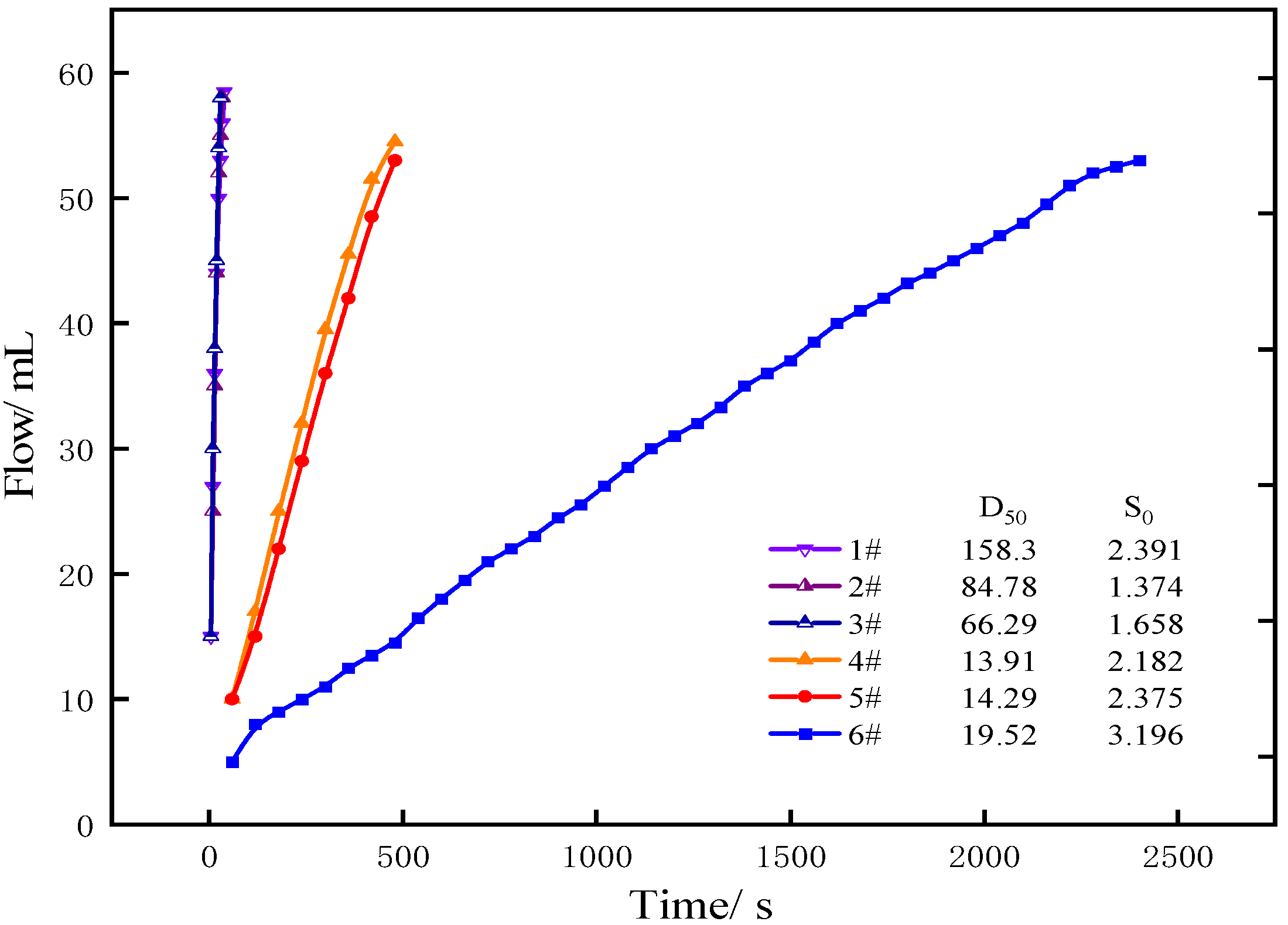
API filtration experiments. The crushed OSR samples were screened with a vibrating sieve, and the OSR samples with different particle sizes and particle size distributions after screening were prepared with simulated water to prepare 70 g of suspension with an OSR sample concentration of 10%. The suspension was numbered (as shown in
Table 2) and slowly poured into the API water loss meter, 1.4 MPa pressure was applied, the volume of filtrate at different times was recorded, the filtration rate and the moisture content of the filter cake and the solid content in the filtrate were calculated, and the effects of particle sorting and particle size on the filtration rate were analyzed in combination with the particle size test results.
Visualization experiment of channeling plugging. As shown in
Figure 1, in order to observe the accumulation and plugging process of particles in the channeling fractures during the injection process, a microscopic visualization bead-clamping model is made of glass microbeads, glass plates, and copper plates to carry out the visualization experiment of channeling plugging. The upper slender space is used to simulate the channeling fractures, and the lower uniformly and densely laid glass microbeads with a diameter of 0.2–0.4 mm are used to simulate the reservoir matrix.
The OSR suspension is dyed with brilliant blue and injected into the visualization model with a micro pump to observe the accumulation of OSR particles in the upper fractures.
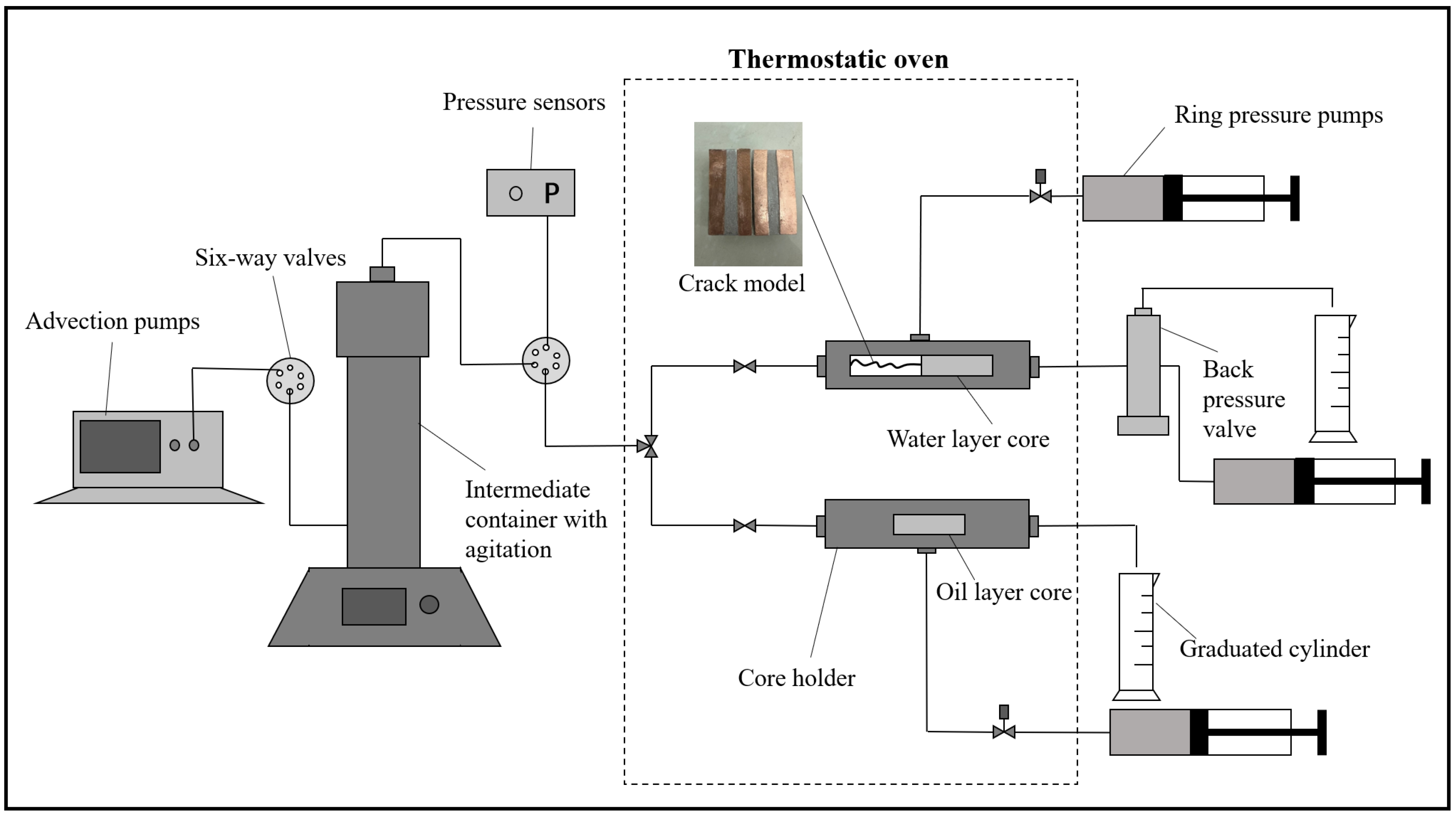
Core flow experiments. Figure 2 shows a channeling simulation model combining a fracture and synthetic cores. The fracture model is constructed by assembling two longitudinally split halves of a steel core. To simulate fracture wall roughness, epoxy resin is applied to the split surfaces, followed by bonding silica sand to create artificially roughened interfaces. Subsequently, 1.5 mm-thick copper sheets are adhesively mounted on both split surfaces using epoxy resin, establishing a controlled fracture width of 3 mm [
20,
21]. The constructed fracture model is then connected in series with the aquifer core. An outlet backpressure of 4 MPa is applied to simulate a high-pressure aquifer. The oil-zone core is connected in parallel with the aquifer core. The core properties (porosity and permeability) were measured beforehand. The aquifer core is saturated with simulated water. The oil-zone core is saturated with simulated oil and then subjected to water flooding until reaching a residual oil saturation of 20%.
To avoid sedimentation of OSR particles, the prepared suspension is loaded into an intermediate vessel with a stirring function and stirred continuously. The injection rate of the suspension is 1 mL/min, and the experimental temperature is 100 °C.
To compare the plugging effect of OSR particles with different particle size combinations on the channeling groove, two sets of displacement experiments are designed for physical model experiments. In experiment 1, 5 mL of 7# suspension with a small particle size is injected to temporarily plug the oil layer, and then 4 mL of 3# suspension with a slightly larger particle size and better sorting performance is injected to plug the channeling tank. The process of experiment 2 is the same as that of experiment 1, except that the two slugs are 6# suspensions with small particle sizes and poor sorting.
After the suspension is injected, heat is continued for 6 h to coalesce the OSR particles. Then, the water flooding is reversed from the outlet of the core of the water layer to test the plugging strength and residual resistance coefficient. After the experiment, the reverse water flooding is carried out separately for each artificial core and fracture model composed of the channeling model, and the plugging effect of the plugging agent on each part of the channeling model is tested.
The pressure changes in the experiment are recorded by a pressure sensor. The permeability of the artificial core is calculated according to Equation (2), and the residual resistance factor
RRF is calculated according to Equation (3).
4. Experimental Results and Discussion
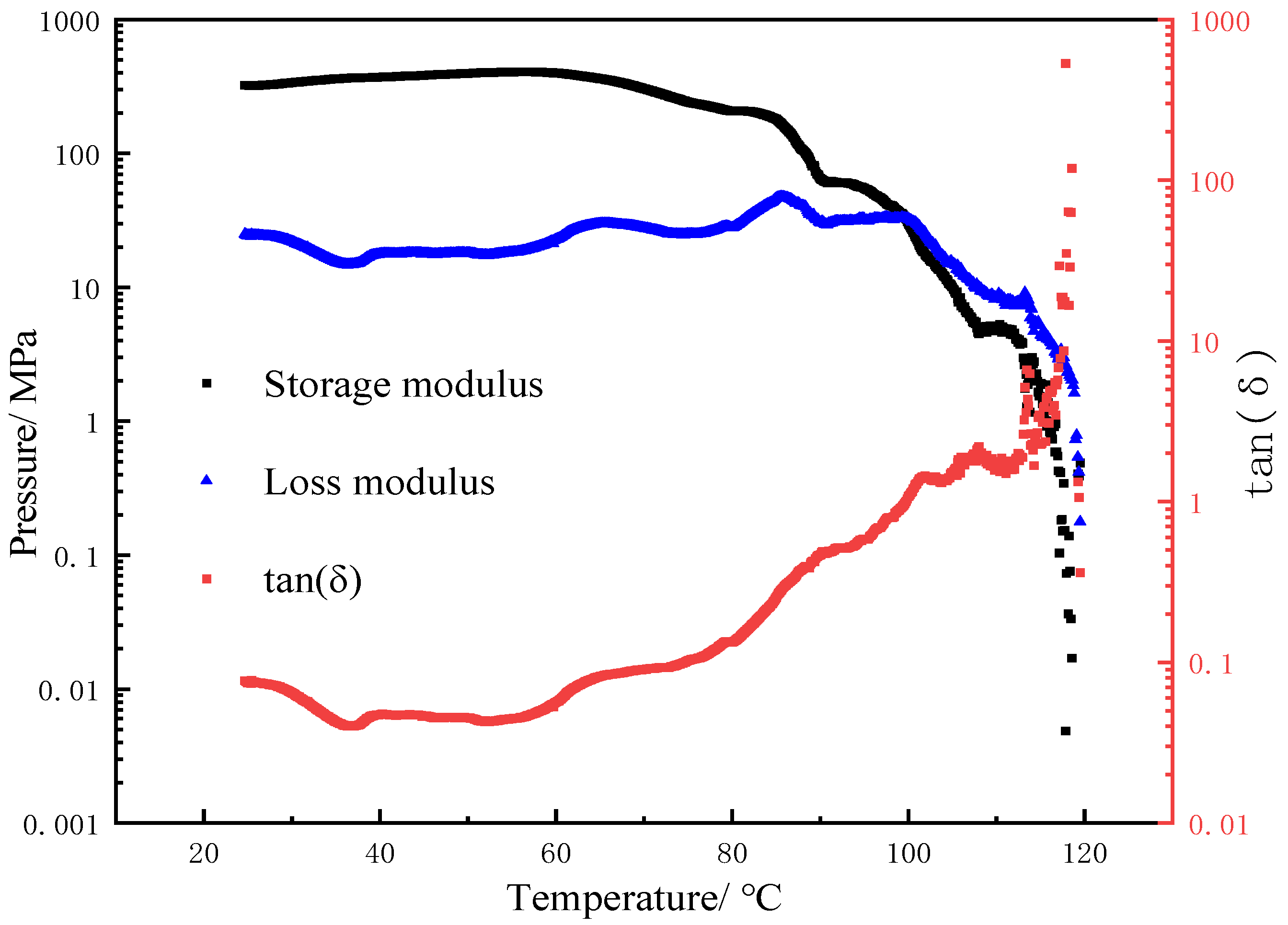
The thermomechanical properties of OSR. The molecular chain movement and structural changes inside the material can be represented by the storage modulus (G′), loss modulus (G″), and loss factor (tanδ) in the dynamic thermomechanical analysis spectrum. As can be seen in
Figure 3, when the temperature is lower than 80 °C, the change in G′ of the oil-soluble resin is small. At this time, OSR has not undergone glass transition and mainly shows the characteristics of a brittle solid. When the temperature is between 80 and 100 °C, G′ > G″. OSR mainly shows the characteristics of elastic solids with high viscoelasticity. When the temperature is higher than 100 °C, G′ decreases rapidly. At this time, G′ < G″ mainly shows the characteristics of a high-viscosity fluid.
The reservoir temperature studied in this paper is 100 °C. As shown in
Figure 3, OSR particles are characterized by high viscoelastic elastic solids at 100 °C, so OSR particles can coalesce into a resin whole with high strength at this temperature, which has the conditions for sealing channel cracks.
Viscosity Testing. A dial reading of 3 was obtained at 100 rpm, which was converted to an apparent viscosity of 9 mPa·s using Equation (4). This viscosity value approximates that of water (1 mPa·s at 20 °C), demonstrating suitability for field pumping requirements.
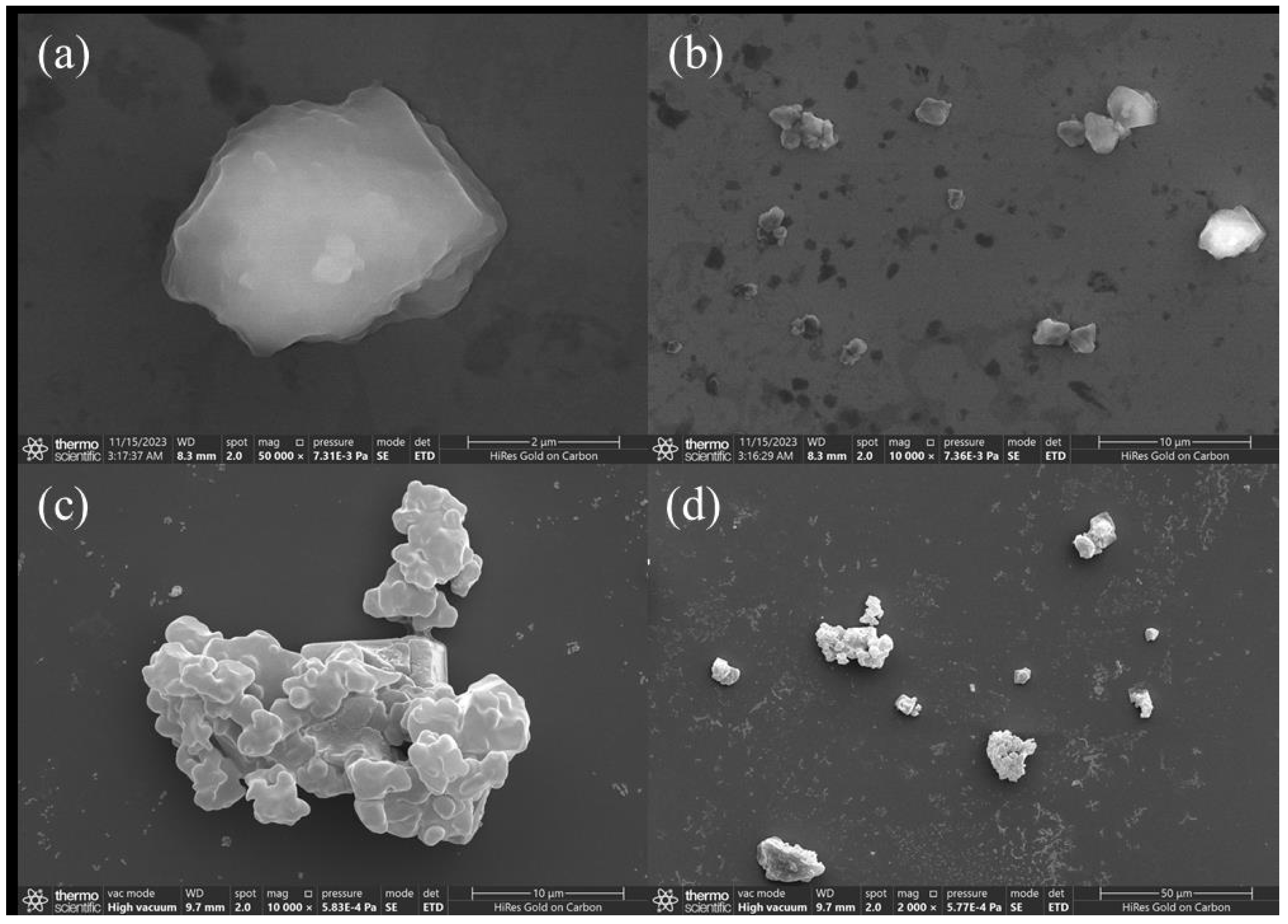
The microscopic morphology of OSR particles before and after coalescence. The microscopic morphologies of the OSR suspension at room temperature and 100 °C are shown in
Figure 4. Before heating and coalescence, the oil-soluble resin particles are dispersed as single particles, and the particles have edges and corners. However, after heating at 100 °C for 6 h, the particles appear aggregated and bonded, and the particle size is significantly increased.
This is because, after the OSR particles adsorb the cationic surfactant DTAC, the surface changes from hydrophobic to hydrophilic, promoting its dispersion in aqueous solution. At the same time, the double electric layer structure formed on the surface of OSR avoids particle aggregation through electrostatic repulsion. Under high temperatures and high salt conditions, the thermal motion of particles is intensified and accompanied by the compression of the double electric layer, promoting particle coalescence. Experiments have confirmed that 1% DTAC can ensure that OSR particles do not coalesce in simulated water at 100 °C for 2 h and can completely coalesce and stratify after more than 5 h. Combined with the DMA test results, the OSR suspension has good dispersion during the injection process and can gradually coalesce into agglomerations under high-temperature conditions after entering the formation and adhere to the rock wall to form a high-strength plugging zone.
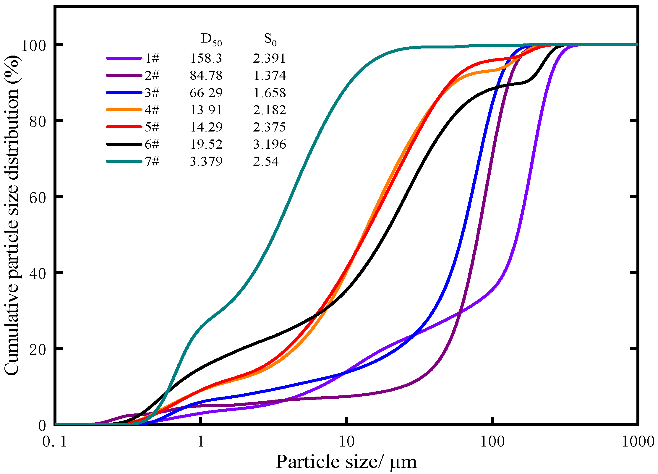
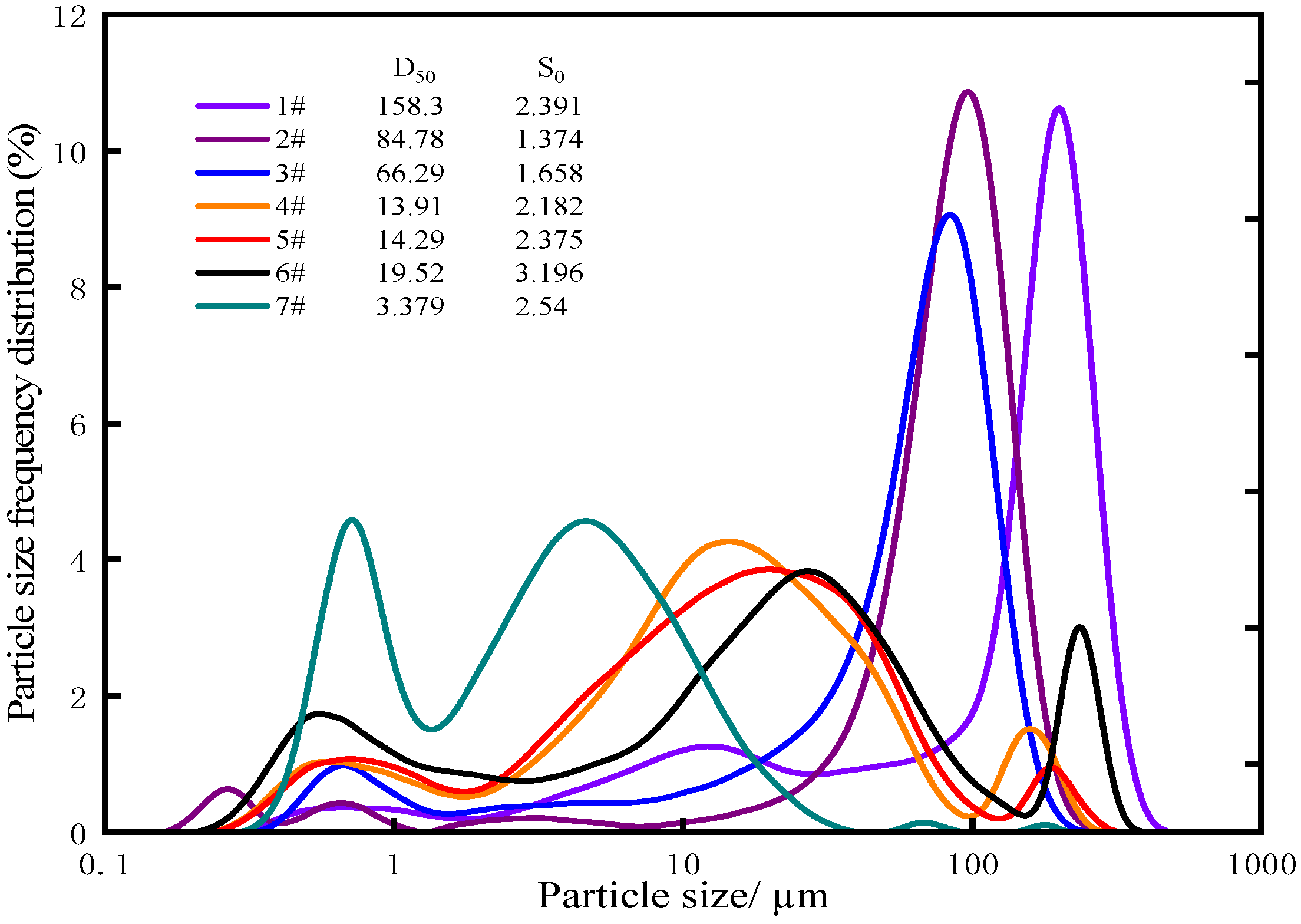
Particle size and sorting of OSR particles. As can be seen in
Figure 5 and
Figure 6 and
Table 2, as the mesh number of the sieve increases, the average particle size of the particles gradually decreases. However, the particle size distribution of the sample shows the characteristics of polydispersity. Among them, the sorting coefficient of the unscreened sample 6# reaches 3.20. This is mainly due to the agglomeration of fine particles that easily occurs during the crushing and screening process of OSR particles. Therefore, considering the average particle size and sorting coefficient comprehensively can be evaluated more accurately.
Rapid filtration loss of OSR is the primary prerequisite for reducing injection pressure, increasing the filling degree of plugging agents in channeling fractures, and then forming a high-strength selective plugging zone. As shown in
Figure 7, for samples 1–3#, the D
50 is relatively large,
S0 is relatively small, the suspension can filter out quickly, the moisture content of the filter cake is less than 20%, and the solid content in the filtrate is less than 0.1%. In contrast, for samples 4–5#, with smaller D
50 and larger
S0, the filtration loss rate is much slower, and the moisture content of the filter cake and the solid content in the filtrate are relatively high. The D
50 of sample 6# is the same as that of samples 1–3#. However, among samples 1–6#, sample 6# has the largest
S0. Sample 6# has the smallest filtration loss rate, the highest moisture content in the filter cake, and the highest solid content in the filtrate. For sample 7#, since the particle size is generally smaller than the pore size of the filter paper, most particles pass directly through the filter paper, so an effective filter cake is not formed.
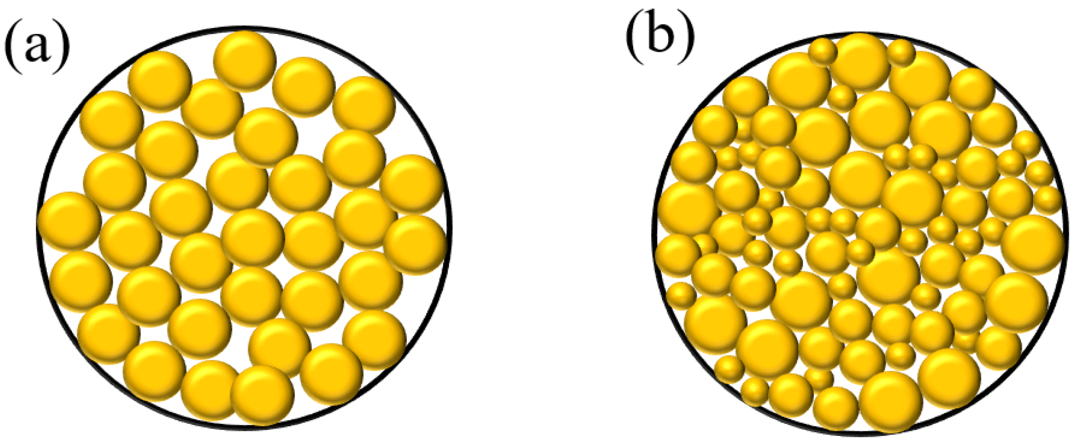
As shown in
Figure 8, well-sorted large particles are conducive to bridging and forming a highly permeable filter cake with high porosity, accelerating the filtration loss of free water in the suspension. Poorly sorted particles form a skeleton structure by bridging large particles, and small particles fill the skeleton gaps to form a filter cake [
22,
23]. This kind of filter cake is dense and has low permeability. This is conducive to forming a matrix temporary plug at the injection end face but not conducive to rapid filtration loss to form a high-solid-content OSR slug in the fracture [
24].
Unlike drilling plugging, the filtrate lost from the suspension will enter the matrix pores. According to the “1/3 bridging rule” [
25,
26], if the content of solid particles in the filtrate is high, then 1/7D pore throat < D particles < the 1/3D pore throat. The particles will bridge in the formation, block the free water filtration channel, and then be unable to form a high solid content OSR filling slug in the channeling groove cracks. Therefore, particle size and particle sorting are the common factors that determine the filtration rate, and the content of small particles in the sample should be reduced as much as possible to increase the filtration rate and the thickness of the filter cake.
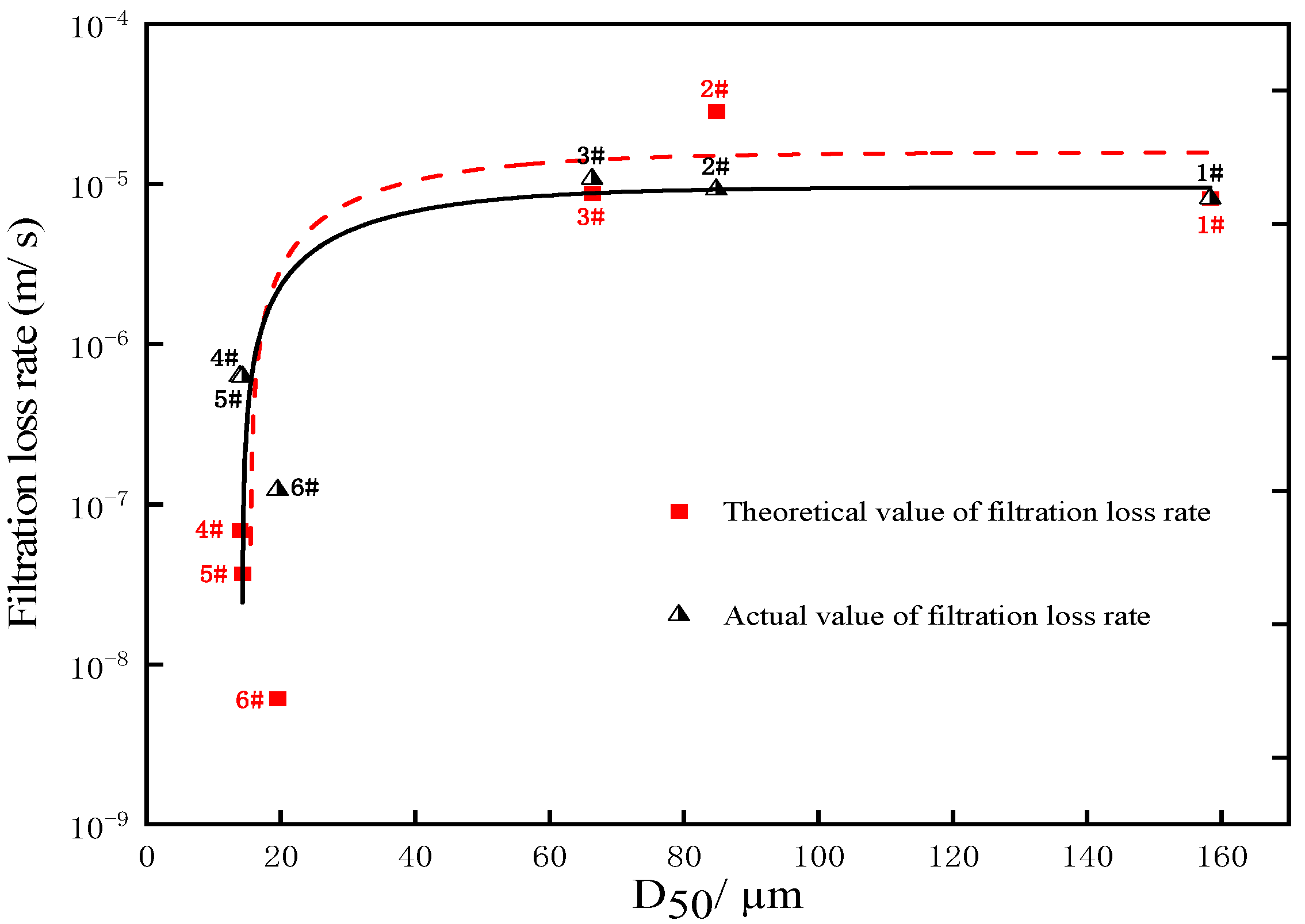
Shun Nomura et al. proposed a modified KC equation based on the particle size distribution curve (PSD) of soil particles to describe the influence law of parameters such as average particle size, sorting coefficient, and porosity on filter cake permeability [
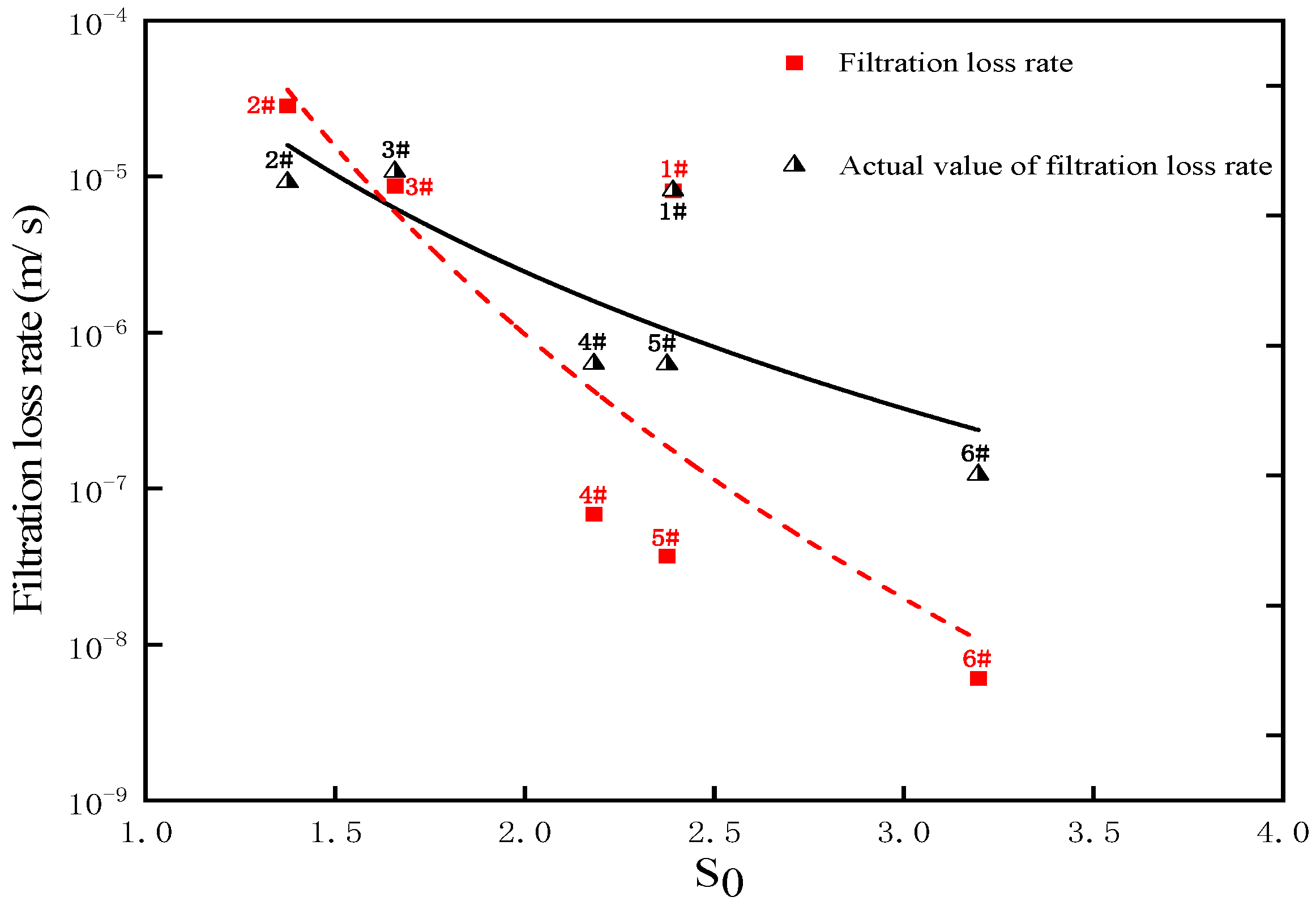
27], as shown in Equation (5). In this paper, the mathematical model is used to calculate the theoretical value of the filtration velocity of each sample, as shown in
Table 3, and the influence of D
50 and the sorting coefficient
S0 on the filtration velocity is analyzed by comparing the theoretical filtration velocity with the actual filtration velocity, as shown in
Figure 9 and
Figure 10.
The data analysis results show that the filtration loss law of the OSR particles used in this paper better conforms to this theoretical model. As shown in
Figure 9 and
Figure 10, when D
50 is less than 40 μm, the filtration loss rate drops sharply. The smaller the sorting coefficient, the faster the filtration loss rate. Therefore, OSR particles with larger particle sizes and better sorting should be selected for water plugging. Since the relevant parameters of this model are directly derived from the physical properties and PSD curves of the samples, it is very convenient to simulate the filtration performance of different samples.
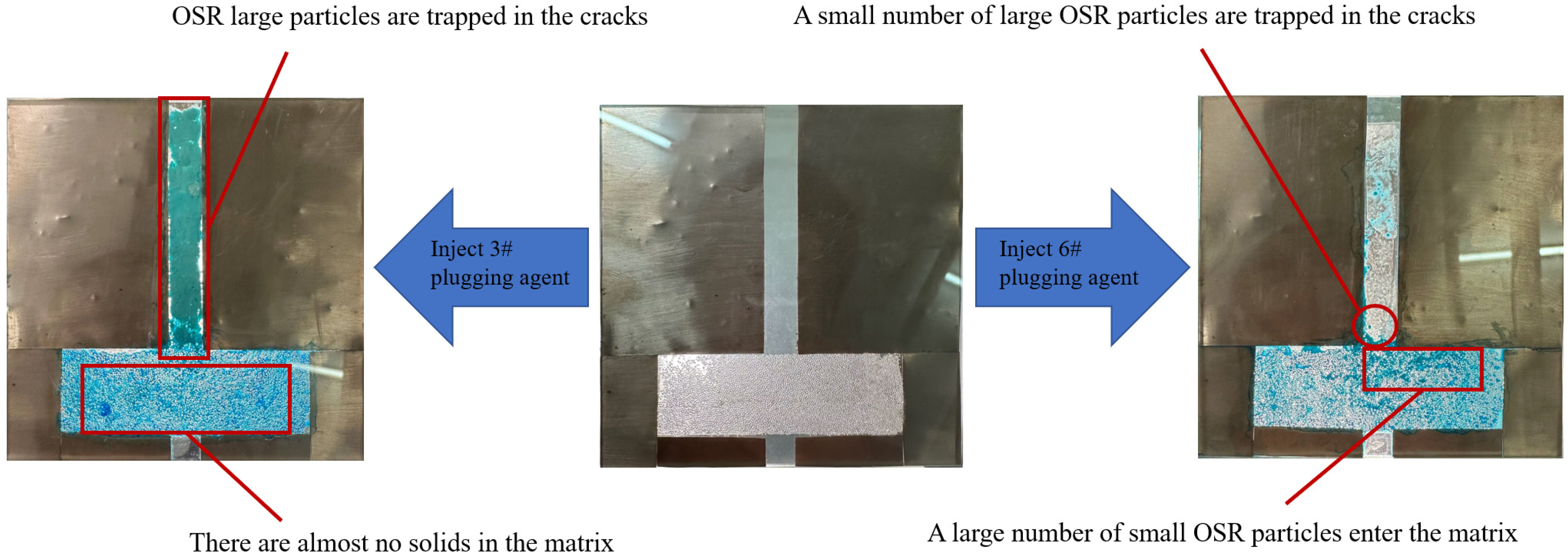
Visualization experiment of channeling plugging. As shown in
Figure 11, during the injection of 3# plugging agent with large particles and good sorting, the blue-free water in the suspension is quickly filtered out, the OSR particles do not form blockages in the matrix pores, and the white OSR particles accumulate in the cracks to form a long accumulation plugging zone.
When the 6# plugging agent with a small particle size and poor sorting is injected, the plugging agent can be injected quickly in the initial stage, and a large number of OSR small particles enter the pores of the matrix and are retained; with an increase in the injection amount, the follow-up plugging agent is difficult to inject, and some OSR large particles are accumulated in the cracks, but the filling ratio is small, and the moisture content of the filter cake formed is very high.
The experiment confirmed the influence of particle sorting and particle size on the filtration velocity and the degree of filter cake accumulation through the intuitive visual method, that is, the selection of OSR particles with larger particle size and better sorting performance can form a tightly filled high-solid plug in the channeling groove cracks.
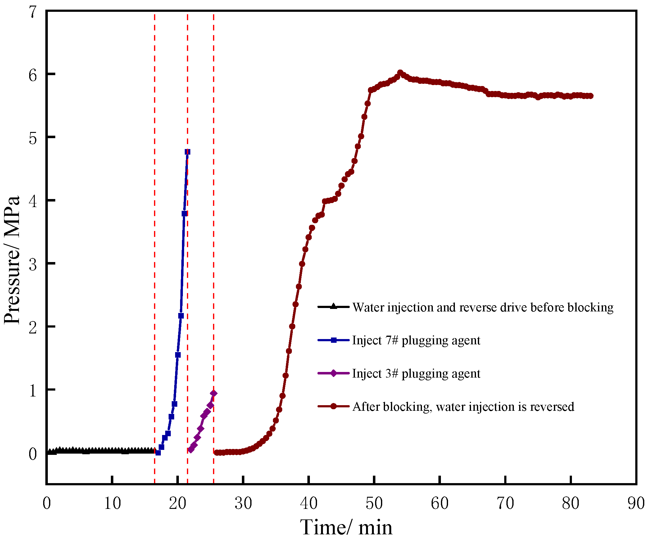
The plugging performance of OSR large particles with good sorting performance on the channeling model. Reverse water flooding from the tail end of the core 1-1 of the water layer was carried out to simulate water channeling. As shown in
Figure 12, the water flooding pressure was only 0.02 MPa. During the experiment, a small amount of water flowed out from the tail end of the core of the oil layer, while a large amount of water flowed out from the forward injection port, indicating that there was a risk of water channeling.
Firstly, the slug of the 7# plugging agent was injected forward. During the injection process, the pressure rose rapidly to 4.9 MPa, and only a small amount of liquid was discharged from the tail end of the oil core 1-2, which showed that the 7# slug first formed a temporary plug at the end face of the oil core 1-2 with lower pressure.
After the transfer to the 3# plugging agent, the pressure slowly rose to 0.9 MPa, and colorless liquid continuously flowed out from the tail end of the core 1-1 of the water layer. This indicated that, under the temporary plugging action of the 7#, the subsequent slug of the 3# plugging agent changed its flow direction and flowed to the core 1-1 of the water layer, and the particles did not cause blockage in the pores of the water layer matrix.
After the injection of the agents was completed, heating was continued for 6 h, and then, reverse water flooding was carried out from the tail end of the core 1-1 of the water layer. It could be observed that the water flooding pressure rose rapidly, and finally, the pressure stabilized at 5.65 MPa. The residual resistance coefficient was 282.5, and there was no liquid flowing out from the tail end of the oil core and the forward injection port of the plugging agent, which confirmed that the OSR large particles with good sorting properties had a strong plugging effect on the tandem model of the channeling model 1-3 and the water core 1-1.
After the experiment, the reverse water flooding was carried out on the water core 1-1, the oil core 1-2, and the fracture model 1-3 to verify the plugging of each part of the channel channeling model by the OSR particles. As shown in
Figure 13 and
Table 4, the plugging pressure of core 1-1 in the water layer is 0.02 MPa, the plugging pressure of fracture model 1-3 is 5.01 MPa, and the
RRF is 250.5, which confirms that OSR only produces a plugging effect in the fracture model. As shown in
Figure 13, after the experiment, the crack model was opened, and the OSR particles were tightly packed in the cracks and consolidated into high-strength bulk resin.
The plugging pressure of core 1-2 of the oil layer is 0.06 MPa, which is the same as the water flooding pressure before plugging, which proves that the temporary plugging layer formed by the injection of 7# plugging agent into the end face can completely remove the blockage and restore the permeability of the oil layer under the action of reverse flooding pressure and simulated oil dissolution.
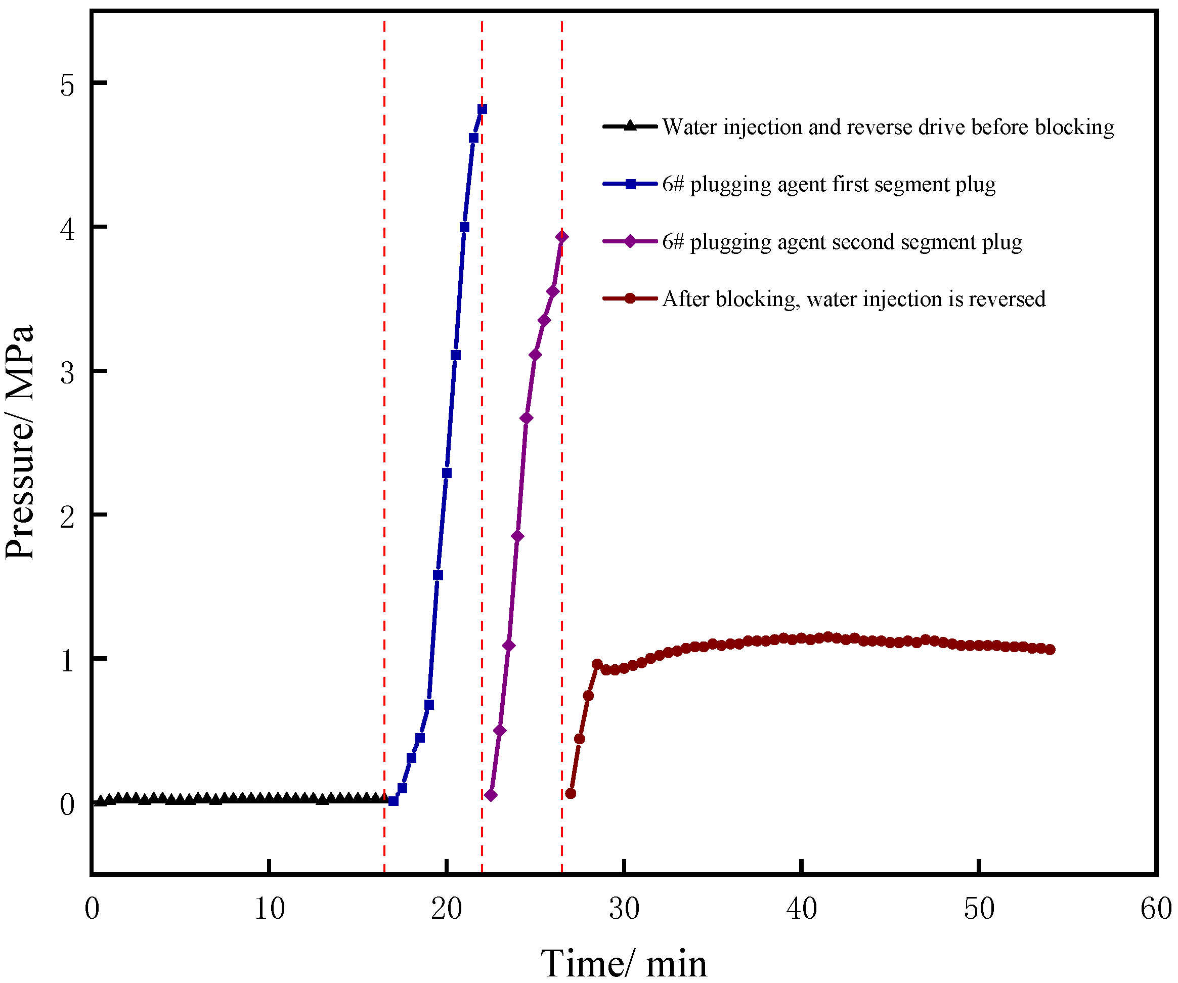
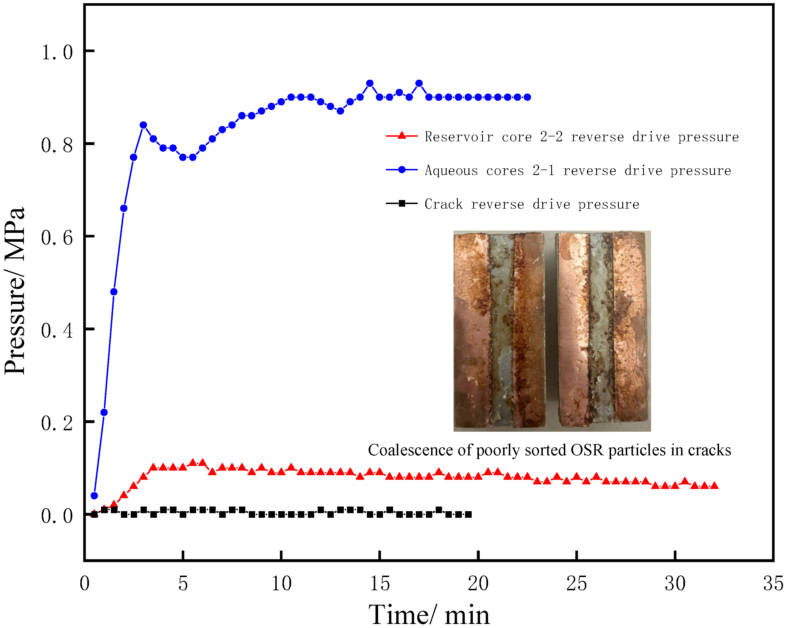
The plugging performance of small OSR particles with poor sorting performance on the channel channeling model. As shown in
Figure 14, the water flooding pressure is only 0.01 MPa, there is a small amount of water flowing out at the tail end of the oil layer core, and a large amount of water is flowing out from the forward injection port of the plugging agent, indicating that there is water channeling.
The
Section 1 plug was injected with 6# plugging agent, the pressure rose rapidly to 4.8 MPa, and only a small amount of liquid was discharged from the tail end of the oil layer core 2-2, indicating that the
Section 1 of the 6# section of the plug first formed a temporary plug on the end face of the oil layer core 2-2 with lower pressure.
When the second stage of the 6# slug was transferred, it can be observed that a small amount of milky white liquid flowed out from the tail end of core 2-1 of the water layer, and the pressure of the pressure sensor rose rapidly to 3.9 MPa. This shows that, under the temporary plugging action of the 6# plugging agent in the
Section 1, the liquid flow direction of the 6# plugging agent in the
Section 2 flows to the core 2-1 of the water layer, but because the 6# plugging agent contains more OSR small particles, the small particles will enter the matrix pores on the surface of the core to form a temporary plugging layer, resulting in a rapid increase in injection pressure.
After the plugging agent is injected, the heating is continued for 6 h to wait for the resin to coalesce completely, and then, the reverse water flooding starts from the tail end of core 2-1 to the whole, the overall plugging pressure is only 1.0 MPa, the residual resistance coefficient is 100, and the liquid flows out at the forward injection port of the plugging agent. The results indicated that the OSR particles with poor sorting did not have a good plugging effect on the channeling groove crack 2-3 and the water layer core 2-1.
After the experiment, the reverse water flooding was carried out on the water core 2-1, oil core 2-2, and fracture model 2-3 to verify the plugging of each part of the OSR particles. As shown in
Figure 15 and
Table 4, the plugging pressure of core 2-1 in the water layer is 0.9 MPa, the
RRF is 90, the plugging pressure of fracture model 2-3 is 0 MPa, and the plugging pressure of core 2-2 in the oil layer is 0.02 MPa. After the experiment, it was found that the crack model only formed a thin film after a small amount of OSR consolidation on the crack wall and failed to form a complete OSR block plug, as shown in
Figure 15. It is confirmed that the 6# plugging agent has only a weak temporary plugging effect on the core of the water layer and does not play a plugging role in the channeling groove cracks.
The reverse flooding pressure of oil layer core 2-2 is 0.06 MPa, which is the same as the water flooding pressure before plugging, indicating that the 6# plugging agent forms a temporary plugging layer at the injection end face, and the blockage can be completely lifted and the permeability of the oil layer can be restored under the dissolution of the reverse flooding pressure and the simulated oil.


 ,
, 

