Abstract
With the expansion of offshore oil and gas resources to deepwater areas, the problem of the vortex-induced vibration of marine risers, as a key structure connecting offshore platforms and subsea wellheads, has become increasingly prominent. At present, there are few reviews on the vortex-induced vibration of flexible risers. This review provides a detailed discussion of vortex-induced vibration in marine risers. This review begins with the engineering background. It then systematically analyzes the key factors that influence VIV response. These factors include the riser’s structural parameters, such as aspect ratio and mass ratio. They also include the external fluid environment. Next, this review evaluates current VIV suppression strategies by analyzing specific experimental results. It compares the effectiveness and trade-offs of passive techniques. It also examines the potential and limitations of active methods, which often use smart materials, like piezoelectrics. This study highlights the major challenges in VIV research today. These challenges relate to prediction accuracy and suppression efficiency. Key problems include model uncertainty at high Reynolds numbers and the practical implementation of suppression devices in engineering systems. Finally, this paper presents an outlook on the future directions. It concludes that an intelligent, full-lifecycle integrity management system is the best path forward.
1. Introduction
With the increasing global demand for energy, the exploration and development of offshore oil and gas resources are gradually advancing to deeper and more complex sea areas. In this process, a flexible riser system is the key lifeline to connect the subsea wellhead with the offshore production platform, and its safety and reliability are very important. These risers are usually slender flexible structures with a high aspect ratio for transporting oil and gas from the seabed to the floating platform. However, in deepwater environments, these structures are inevitably subjected to complex environmental loads, such as ocean currents, triggering a fluid–solid coupling phenomenon called vortex-induced vibration [1].
VIV is caused by the coupling of periodic vortex shedding caused by fluid flow and the vibration of the riser structure. The fatigue damage of the riser is mainly caused by the vortex-induced vibration caused by the interaction between the external environment and the riser [2,3]. Therefore, in the field of marine engineering, a large number of studies on the influencing factors and suppression methods of the vortex-induced vibration of marine risers under complex sea conditions have been carried out, which has become a research hotspot in the field of marine engineering. When fluid flows through the bluff body structure at a certain flow rate, especially in the marine structure equipment, it is very common to use circular cross-section equipment. When the fluid flows through the circular structure equipment, it will produce a wake vortex that alternately falls off in the rear. The vortex street effect is explained as follows [4]. When the fluid (such as water or air) flows through the flexible riser, the fluid forms a boundary layer on the surface of the riser due to the viscous effect. At the separation point, the vortex generated by the boundary layer separation swings to both sides with the lateral motion of the riser and overlaps and falls off in the near wake field. In the process of backward motion, the vortex pairs with opposite rotation directions fall off alternately, and the vortex energy continues to dissipate until the vortex breaks up and disappears, which is the formation process of Carmen vortex street. This shedding causes the fluid to exert alternating lift and drag on the structure, which leads to the periodic vibration of the riser [5]. With the development of ultra-deepwater resources toward ultra-deepwater and long-span risers, the response mechanism of the VIV characteristics of flexible risers under complex conditions, such as non-uniform flow and multi-riser interference, needs to be further revealed. Vortex-induced vibration of flexible marine risers brings together difficult and important problems in the field of mechanics, such as turbulence, flow separation, the incomplete transition of the shear layer, and drift of separation point [3]. And the high coupling between fluid motion and structural response increases the difficulty of solving this problem. So far, the academic community has not completely solved this problem.
The experimental study of vortex-induced vibration began in the middle of the 20th century. Feng [6] first systematically tested a single-degree-of-freedom elastically supported cylinder in a wind tunnel. As the research advances, scholars [7] gradually turned the experimental environment to the flume, focusing on the vibration characteristics of cylinders with a low mass ratio (m *) and low damping ratio (ξ), which are more in line with the actual working conditions of marine risers. In recent years, the team of Khalak [8] and Govardhan [9] improved the accuracy and reliability of the vortex-induced vibration experiment of the cylinder to a new level by improving the experimental device and measurement technology.
In terms of theoretical model development, the wake oscillator model proposed by Hartlen [10] pioneered the theoretical study of vortex-induced vibration. The model has been successfully applied to the vibration analysis of flexible slender structures by Skop et al. [11]. Guo [12] further improved the theoretical model by introducing the influencing factors of internal flow. These theoretical works provide important analytical tools for understanding vortex-induced vibration.
Numerical simulation technology has made significant progress in recent years. The main methods include the discrete vortex method [13], RANS, LES, and DNS [14]. Among them, RANS and LES methods show good practicability in engineering applications. In terms of moving boundary processing technology, fixed grid methods, such as the virtual domain method and immersed boundary method, have become a hot research direction because of their computational efficiency advantages. The development of these numerical methods provides a new research method for the prediction of vortex-induced vibration under complex conditions.
Table 1 lists the advantages and disadvantages of the previous review of the vortex-induced vibration of flexible risers. At present, there are few reviews on the influence of the vortex-induced vibration of flexible risers and the direction of vortex-induced vibration suppression. In this paper, the latest progress and research on the vortex-induced vibration of flexible risers are summarized. The factors affecting vortex-induced vibration are analyzed from various angles, and how to suppress vortex-induced vibration is discussed systematically and in detail. Finally, the current technical bottleneck and future research trends are reasonably proposed, which complements the systematic research in the field of flexible risers and vortex-induced vibration.

Table 1.
Core review literature comparison analysis table.
2. Main Influencing Factors of Vortex-Induced Vibration
2.1. Structural Parameter
2.1.1. Mass Ratio
The mass ratio is the core dimensionless parameter to characterize the inertial effect and fluid force coupling strength of flexible risers, which has a decisive influence on the amplitude–frequency characteristics and modal evolution of vortex-induced vibration (VIV). Under the condition of a low mass ratio, the leading role of the inertial force of the riser is weakened, and the fluid force is more likely to excite high resonance, which leads to the widening of the ‘locking range’ and the intensification of multimodal competition. When the mass ratio is high, the structural inertia significantly inhibits the accumulation of vibration energy, but it may cause a complex spatial response due to the excitation of high-order modes. The mass ratio of the flexible riser itself does not change the fixed Strouhal constant (about 0.2). However, due to its low mass ratio, the ‘lock-in’ phenomenon of the vortex-induced vibration will occur in a very wide flow rate range. In this region, the vortex shedding frequency is forced to synchronize with the structural vibration frequency, so that the effective Strouhal number is no longer a constant, but decreases significantly with the increase in the flow rate. The traditional rigid cylinder VIV theory has limitations in the prediction of the mass ratio effect. Especially for the three-dimensional fluid–solid coupling characteristics of flexible slender risers, it is necessary to reveal its dynamic equilibrium mechanism through physical model experiments. In this section, combined with the experimental observation data, the regulation law of mass ratio on the vibration amplitude, frequency synchronization, and modal transition of flexible risers is systematically analyzed, and its optimization threshold in the vibration suppression design of deep-sea engineering is discussed.
Zhang [18] adjusted the riser mass ratio by filling air, water, and sand in the experiment of the Dalian University of Technology, and found that the low mass ratio significantly enhanced the fluid–solid coupling effect, resulting in the expansion of the locking interval and an increase in the amplitude. For example, when the mass ratio decreases from 6 to 3, the transverse amplitude increases by about 40%, and the modulation effect of the in-line vibration on the transverse vibration is more significant.
Duan [19] simulated the VIV response of a flexible riser with mass ratio by developing numerical software. The results show that under a low mass ratio, the in-line vibration dominates the energy dissipation, and the trajectory gradually changes from an ‘8’ shape (the transverse frequency is twice the in-line direction) to a ‘0’ shape (the frequency is equal).
2.1.2. Slenderness Ratio
The slenderness ratio (L/D, the ratio of riser length to diameter) is the core parameter to characterize the three-dimensional fluid–solid coupling characteristics of flexible risers, which significantly affects the spatial modal distribution, energy transfer mechanism, and fatigue damage mode of vortex-induced vibration (VIV). For short risers with a low slenderness ratio (L/D < 50), the end constraint effect dominates the vibration response, the vortex shedding behavior is similar to the flow around a two-dimensional cylinder, and the vibration energy is concentrated in the fundamental frequency mode. However, due to the enhanced structural flexibility of the flexible riser with a high slenderness ratio (L/D > 200), the non-uniformity of the flow field along the axial direction is intensified, which induces multi-modal competition, traveling wave propagation, and modal transition, resulting in the failing of the traditional low-dimensional model prediction. For flexible risers with a large slenderness ratio, the vortex-induced vibration is no longer a simple single lock-in due to its numerous and dense natural vibration modes. Instead, with the increase in the flow velocity, the vibration modes will gradually ‘climb’, resulting in a unique ‘step-by-step’ variation in the effective Strouhal number with the jump of modes. In addition, the increase in the slenderness ratio will also amplify the interaction between the three-dimensional turbulent structure and riser vibration, forming complex spatiotemporal evolution dynamics (such as the coupling of local vortex shedding and global vibration). Based on the physical model experiment, this section systematically reveals the regulation law of the slenderness ratio on the spatial distribution of the vibration amplitude, frequency locking range, and fatigue hotspot position of flexible risers, and provides a theoretical basis for the anti-vibration design and health monitoring of deep-sea long-span risers.
Li Peng [20] conducted an experimental study on the sensitivity of the vortex-induced vibration suppression of deep-sea risers under the action of stage flow in a large wave–current coupling test tank. The test riser model was 6.2 m long and the slenderness ratio was 310. The model material was a copper tube. The upper 1.2 m of the riser was in a uniform and stable flow field, and the lower 5.0 m was in still water. Trapezoidal cross-section double-helix and triple-helix guide plates with a helix height of 0.25 D were used as vibration suppression devices. The effects of different coverage rates on the suppression efficiency and vibration frequency of the vortex-induced vibration of risers were studied, and their sensitivity laws were analyzed. The results show that the coverage of the spiral guide plate on the riser has an important influence on the suppression of vortex-induced vibration. In the sensitive area, the coverage rate makes a significant transition due to the influence of suppression efficiency and vibration frequency. When the coverage exceeds the sensitive area, the suppression efficiency is high and the change is small, while the vibration frequency of the riser is significantly reduced.
Based on the marine riser solver viv-FOAM-SJTU, Li Min [21] used the slice method to simulate the vortex-induced vibration of smooth risers and risers with different lengths of splitter plates under the condition of a uniform flow with Re = 4000. The dynamic response characteristics, such as frequency response, displacement response, and vortex shedding mode of risers under different working conditions, were compared and analyzed. It was found that the vortex-induced vibration of the riser can be suppressed to a certain extent by adding a splitter plate within a certain length range, and the suppression effect is closely related to the length of the splitter plate. When the ratio of the length of the splitter plate to the diameter of the riser (L/D) increases to 0.5, the amplitude of the riser increases instead.
2.1.3. Cross-Sectional Shape and Surface Structure
The cross-section shape and surface structure are the key design parameters to control the energy input and dissipation of the vortex-induced vibration (VIV) of flexible risers. By actively intervening in the wake vortex generation mode and boundary layer flow characteristics, the resonance mechanism of fluid–solid coupling can be fundamentally weakened. The periodic vortex shedding (Karman vortex street) caused by the symmetry of the traditional cylindrical section is the main cause of the large amplitude vibration. Rather than circular cross-sections (such as ellipse, hexagon, D-shaped, etc.), the lift fluctuation is significantly reduced by changing the position of the flow separation point and the spatial evolution path of the wake vortex. In addition, surface bionic structures (such as helical strakes, grooves, or flexible cladding) further suppress the spatiotemporal correlation of vortex shedding by producing three-dimensional turbulent structures, delaying flow separation, or enhancing energy dissipation. However, most of the existing studies focus on idealized cross-sections, and there is still a lack of systematic experimental verification of the multi-scale fluid–solid coupling mechanism of complex geometries and rough surfaces. In this section, combined with a high-precision flow field diagnosis and vibration response measurement, the regulation effects of cross-section shape optimization and surface structure design on VIV amplitude–frequency characteristics, modal stability, and fatigue life are quantitatively analyzed, which provides the experimental basis for the bionic vibration suppression design of deep-sea risers.
The influence of the cross-sectional shape and surface structure of the flexible riser on the Strouhal number directly changes its vortex-induced vibration characteristics from the root of fluid dynamics. The standard smooth circular cross-section is used as a reference, and its flow separation point is not fixed, resulting in a Strouhal number of about St ≈ 0.2 at a typical engineering Reynolds number. In stark contrast, the square cross-section has a sharp leading edge that forcibly fixes the flow separation point and forms a wider wake, which results in a significant reduction in the vortex shedding frequency and a decrease in its Strouhal number to St ≈ 0.13–0.15. The analysis of the D-shaped cross-section reveals the key influence of the directivity: when the plane is facing the flow, it appears as a typical bluff body, and the separation point is fixed at two sharp corners, resulting in a low Strouhal number similar to the square cross-section. On the contrary, when the circular surface is facing the flow, its shape is closer to the streamline body, and the wake is significantly narrowed, which makes the Strouhal number increase significantly, and its value is closer to the circular section. Therefore, the change from circular to square and then to a D-shaped cross-section fully shows that, whether the separation point is fixed or not, the asymmetry of the cross-section is the key physical factor that directly reshapes the core parameter of the Strouhal number.
Professor Song Jining’s [22] VIVACE device, using vortex-induced vibration for the ocean current energy collection mark-β method, used ANSYS 2023 R2 FLUENT software. The flow-induced vibration response of a D-shaped cross-section cylinder with four mass ratios (2, 5, 7, and 10) at a 90° inflow angle is investigated by numerical simulation. The vibration amplitude, frequency, equilibrium position offset, wake vortex shedding mode, and energy conversion efficiency of a D-shaped cross-section cylinder in a cross-flow direction are systematically analyzed. The simulated Reynolds number range is 288–2880, and the corresponding reduced velocity is 2–20. The results show that the mass ratio has a significant effect on the flow-induced vibration of the D-shaped cross-section cylinder, and the mass ratio will change the response branch of the flow-induced vibration of the D-shaped cross-section cylinder. The larger the mass ratio, the lower the reduced velocity corresponding to the galloping of the D-shaped cross-section cylinder; with the increase in the mass ratio, the offset of the equilibrium position of the D-shaped cross-section column decreases relatively. With the increase in the reduced velocity, the response branches of vortex-induced vibration, vortex-induced vibration–galloping vibration, and complete galloping appear in the D-shaped cross-section cylinder. Within the scope of the simulation, the high energy-conversion efficiency of the D-shaped section cylinder appears in the vortex-induced vibration branch, rather than in the galloping branch, when the mass ratio is 10 and the reduced speed is 4.5.
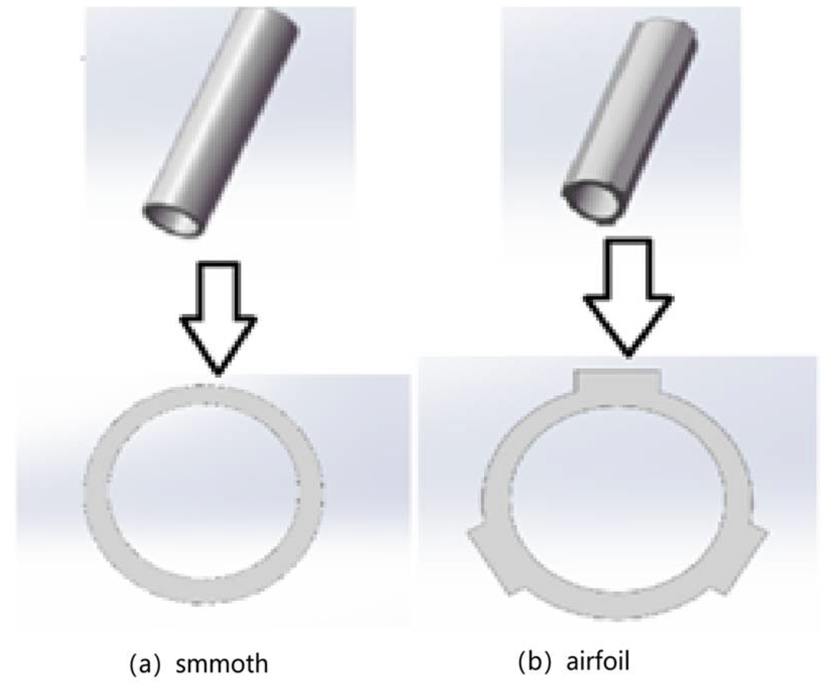
Khalilpasha and Albermani [23] proposed a method to suppress VIV by textured processing on the surface of the tube. Because the texture tube has an origami shape, there are local facets in the longitudinal and cross-sectional directions. Compared with the equivalent smooth tube, this surface structure can significantly increase the extended buckling capacity (as shown in Figure 1a) and can also increase the energy absorption capacity under axial load and improve the crushing performance.
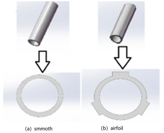
Figure 1.
Surface structure diagram.
Through a numerical simulation, Nikoo et al. [24] found that the texture tube can eliminate the upper part of the branch in the traditional smooth tube. When the pipeline structure vibrates at a high speed, the vibration amplitude will decrease sharply, and the vibration suppression effect is more significant.
Liu et al. [25] simulated a two-dimensional flow around the submarine pipeline with a spoiler by the numerical method. The numerical results show that when the gap ratio is 0.3, the spoiler has a better vibration suppression effect and stress condition. In particular, the pipeline with ∆ 60° (∆ represents the angle between the flow direction and the counterclockwise rotation symmetry axis of the first airfoil) is the most effective, as shown in Figure 1b. The above two special-shaped surface structures have been shown to effectively suppress VIV without additional equipment. Because of their excellent performance, they deserve more attention and a further exploration their potential for wider applications. The purpose of this paper is to study the effects of surface modification and section deformation on the vibration response of long, flexible tubes. Specifically, the VIVs of three types of flexible tubes (i.e., textured tube, airfoil tube, and smooth tube) with the same performance are studied. The numerical results are analyzed and compared to verify the VIV suppression effect of the proposed method.
2.2. Coupling Effect of Fluid Environment Parameters
2.2.1. Flow Velocity and Reduced Velocity
Flow velocity is a key factor affecting vortex-induced vibration (VIV). As the flow velocity increases, the vortex shedding frequency increases linearly (determined by the Strouhal number St). When the vortex shedding frequency is close to the natural frequency of the structure, the ‘locking’ phenomenon will be triggered, resulting in a significant increase in the vibration amplitude. However, a too-high flow velocity may complicate the vortex shedding mode (such as high-order mode or turbulence effect) and suppress the vibration. Therefore, the flow velocity not only determines the strength of the fluid force, but also directly affects the resonance risk through the frequency-matching relationship.
The reduced velocity is the core parameter to determine VIV resonance, which combines the flow velocity, the natural frequency, and the geometric size of the structure. When Vr is in the ‘lock-in range’ from 4 to 8, the vortex shedding frequency is synchronized with the natural frequency of the structure, and the vibration amplitude reaches the peak value (the amplitude of the cylinder can reach 0.6–1.0 times the diameter). When this is below or above this range, the frequency mismatch causes the amplitude to decrease. Therefore, the reduced velocity provides a unified dimensionless criterion for predicting and controlling VIV by quantifying the dynamic interaction between the fluid and structure.
Yu [26] pointed out that a reduced velocity represents the ratio of the fluid path to the structural feature size during a structural vibration, which is dimensionless in terms of the flow velocity. The locking range corresponding to the occurrence of a vortex-induced vibration is about 4–10 times the reduced velocity, that is:
Vr is the reduced speed, m/s; V is the transverse flow velocity, m/s; fn is the first-order natural frequency of the underwater cross-flow direction of the submarine cable, Hz; and D is the diameter of the submarine cable, m.
Jin Longdang [27] pointed out that the flow velocity in the riser increased from 0 m/s to 10 m/s, and the reduced velocity increased from 4.3 to 4.45, which led to an increase in the vortex-induced vibration amplitude of the riser. As the internal flow velocity continued to increase to 20 m/s and 30 m/s, the reduced velocity increased to 4.6 and 4.8, respectively. Accordingly, the vortex-induced vibration amplitude of the riser in the transverse direction increased. It can be seen that the internal flow velocity changes the amplitude of the lateral vortex-induced vibration of the riser by affecting the reduced velocity. It is worth noting that the lateral vortex-induced vibration response of the riser caused by the shear flow should generally be asymmetric along the axial direction, but the length of the neutral tube in this study is short, and this asymmetric feature is not fully reflected.
2.2.2. Flow Direction and Spatial Distribution
The flow direction significantly affects the characteristics of vortex-induced vibration. When the fluid flow direction is perpendicular to the structural axis (such as the transverse flow direction of the cylinder), vortex shedding is the most regular and symmetrical, forming a strong periodic lift and exciting a large vibration. If the inflow has a yaw angle (such as tilt or axial flow), the symmetry of vortex shedding is destroyed, resulting in a decrease in lift and an increase in the proportion of drag, and the vibration amplitude may decrease or even disappear. For example, under the combined action of crosswind and downwind, the vibration mode of cable strands of the cable-stayed bridge will be complicated by the deflection of flow direction, and the flow field distribution needs to be adjusted by aerodynamic shape optimization (such as surface grooves).
The spatial distribution reflects the non-uniformity of the flow velocity or flow direction around the structure. For example, in the shear flow of marine risers, the difference of flow velocity at different depths leads to a change in the vortex shedding frequency along the length direction of the riser, which may stimulate multi-order modal vibration and aggravate fatigue damage. In addition, when the flow separation zone around the bluff body structure is disturbed by space (such as adjacent structure interference), the local velocity gradient will change the vortex generation position and shedding sequence, so that the vibration response presents unsteady characteristics, such as intermittent locking or a modal jump.
Ma Yexuan [28] carried out an experimental study on the vortex-induced vibration of risers under the action of incoming flow at an angle of attack. The influence of the angle of attack on the vortex-induced vibration response characteristics and fluid force characteristics of the riser was revealed, and the scope of application of the unrelated principle in the design and analysis of engineering neutral pipes was clarified. When the angle of attack exceeds 30°, the vortex-induced vibration is more likely to excite higher-order modes. The larger the angle of attack is, the lower the equivalent reduced velocity corresponding to higher-order mode excitation is. The vibration displacement of the riser does not decrease with the increase in the angle of attack. The motion trajectory of the riser is generally eight-shaped and crescent-shaped, and the elliptical trajectory appears under specific working conditions. When the angle of attack does not exceed 15°, the fluid force of vortex-induced vibration is less affected. When the angle of attack exceeds 30°, the fluid force characteristics change significantly.
Li [29] analyzed the flow-induced vibration types of the cylinder under different inflow angles and revealed the influence of cross-section geometric characteristics and inflow angle on the vibration response of the cylinder, fluid force, phase change, and wake structure. The results show that the flow angle is an important factor affecting the vibration response and vibration mode of the square cylinder. When the flow angle is 0°, the square cylinder will produce a galloping vibration, the wake structure will shift obliquely, and vortex shedding is high, resulting in the low-frequency and high-amplitude vibration of the cylinder. When the inflow angle is 15° ≤ 0° ≤ 30°, the vibration response of the square column is coupled with the vortex-induced vibration and the galloping vibration. When the inflow angle is 45°, a vortex-induced vibration response of the square column occurs. From the perspective of energy capture, the angle of incoming flow is controlled to make the square cylinder have a galloping response, so as to realize the absorption of ocean energy at a wide flow velocity range.
2.2.3. Fluid Density and Viscosity
Fluid density directly affects the fluid force of vortex-induced vibration (VIV). The higher the density, the stronger the fluid inertia force, resulting in a significant increase in the lift and drag amplitude generated by vortex shedding, which may aggravate the structural vibration. For example, underwater structures are more susceptible to high vibrations caused by strong vortex excitation in seawater (high density) than in air. In addition, the density changes the effective mass of the structure by affecting the additional mass effect (inertial coupling with the surrounding fluid), thereby adjusting the vibration frequency and indirectly affecting the matching conditions of the locking interval.
The fluid viscosity dominates the flow state and vortex shedding mode through the Reynolds number. The high viscosity of low-viscosity fluid easily forms a turbulent boundary layer, resulting in irregular vortex shedding or a three-dimensional turbulent structure, which may inhibit the classical locking phenomenon. Under high-viscosity fluid, the flow is more laminar, the vortex shedding frequency is stable, and the symmetry is enhanced, but viscous dissipation will weaken the vortex energy and reduce the vibration amplitude. For example, the VIV amplitude of high-viscosity crude oil in oil pipelines is usually lower than that of low-viscosity water flow conditions.
Engineering applications need to take into account the coupling effect of density and viscosity. For example, in the design of deep-sea risers, the combination of high-density seawater and low-viscosity characteristics may create a strong vibration, and flexible coatings or active damping systems are required to dissipate energy. Chemical pipelines need to optimize the support spacing for high-viscosity media to avoid low resonance risks. In addition, by adjusting the fluid medium (such as gas injection to reduce density) or surface modification (such as superhydrophobic coating to reduce viscous resistance), the VIV response can be actively regulated to improve the reliability of the structure in complex fluid environments.
Duan [30] studied the VIV dynamic behavior of fluid-conveying flexible risers affected by external shear flow. The effects of internal flow velocity and fluid density on VIV response were mainly examined and analyzed. A time domain model was introduced and elaborated. Then the finite element method was used to discretize the governing equations. Firstly, the validity of the model was verified by comparing the numerical results with the experimental results. Then, the effects of the internal flow velocity and fluid density on VIV dynamics were studied. The results show that when the flexible risers with different internal flow velocities and densities are subjected to external shear flow, a multi-frequency response occurs. At the same shear flow velocity, the average deflection of IL increases with the increase in the internal flow velocity and fluid density. In addition, the internal flow velocity and fluid density have a significant effect on the vibration frequency and root mean square (RMS) displacement in the online (IL) direction and the transverse flow (CF) direction. In addition, mode and frequency transitions can be observed at different internal flow rates and fluid densities. As shown in Figure 2, (a) is the fluid-conveying riser affected by shear flow and (b) is the FEM model (Ui is the internal flow velocity; Ue external flow velocity IL and CF hydrodynamics caused by external shear flow, whose velocity increases linearly from Ue, min to Ue, max; and i and j often represent the node number in the finite element model).
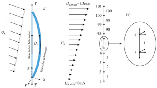
Figure 2.
Sketch of (a) a fluid-conveying riser subjected to shear current and (b) the FEM model.
M. Holzner [31] studied the effect of viscosity on vortex dynamics in homogeneous and quasi-isotropic turbulence by particle-tracking experiment and direct numerical simulations. The results show that viscosity not only destroys the vortex, but also locally generates the vortex and changes its direction (viscous tilt). The authors also analyzed the influence of viscosity on the amplitude of the vortex and found that, although viscosity mainly destroys the vortex, about one-third of the events are caused by viscosity.
3. Research on the Suppression of Vortex Vibration
3.1. Passive Vibration Suppression Technology
In the research field of suppressing vortex-induced vibration (VIV), passive vibration suppression technology is a classical strategy without an external energy input. The core idea is to directly interfere with the flow field around the structure by changing the geometric shape of the structure itself or installing auxiliary components, aiming to destroy the periodicity and regularity of vortex shedding. For example, adding spiral plates or pits on the surface of the cylinder can effectively disturb the flow and guide it to develop in three dimensions, thus disrupting synchronous vortex shedding along the axial direction of the structure and weakening the influence of the vortex excitation force from the source.
Another common type of passive vibration suppression method is to create an article in the wake region of the structure. By installing a separation plate or a fairing in the wake, the interaction between the shear layers on both sides can be effectively suppressed, or the structure can be streamlined, thereby reducing the flow separation, stabilizing the wake, and preventing the formation of alternating von Karman vortex streets. Because of their simple structure, economic reliability, and low maintenance cost, these passive technologies have been widely and successfully applied in engineering structures, such as marine risers, bridge cables, and high-rise chimneys.
Senga et al. [32] studied the effects of spiral plate coverage and different pitches and screw heights on vibration suppression. Zhu et al. [33] used the computational fluid dynamics (CFD) method to study the vortex-induced vibration of a circular cylinder with a freely rotating triangular fairing. Wang et al. [34] proposed a scheme of installing rotating wings and analyzed the vortex-induced vibration characteristics of conventional marine risers and marine risers with rotating wings by the unsteady numerical calculation method. Wang achieved vibration suppression by controlling the surface roughness of the structure.
Ken et al. [35] studied the influence of the number of screw heads on the suppression effect. When the number of screw heads increases to three, the increase in the number of screw heads had a limited effect on the suppression effect, but increased the average resistance. Gao et al. [36] found that the height of the plate increased, the control frequency and the maximum displacement decreased, and the increase in the pitch delayed the production of the frequency locking zone. However, the range of the frequency locking region increased. Xu et al. [37] further found that the suppression effect of the circular cross-section spiral plate on the vortex-induced vibration response frequency and the in-line displacement was slightly better than that of the square cross-section plate. Ma et al. [38] experimentally studied the suppression effect of the spiral plate on the vortex-induced vibration of the riser under the action of time-varying axial force. Time-varying axial force excitation reduces the suppression efficiency of the spiral plate. Xu et al. [39] studied the suppression effect of the spiral plate under the action of the angle of attack. As the angle of attack increases, the suppression efficiency of the spiral plate decreases significantly. There are usually auxiliary, small pipe cables around the riser. After good arrangement, it can interfere with the development of the boundary layer and play the role of a control rod.
Lu et al. [40] studied the influence of the number of control rods and the installation angle on the suppression effect. When the installation angle of the four control rods was 45°, the suppression efficiency could reach 90%. Xu et al. [41] experimentally observed the suppression effect of the control rod under the action of the angle of attack, and the suppression efficiency of the control rod on the vortex-induced vibration was less affected by the angle of attack.
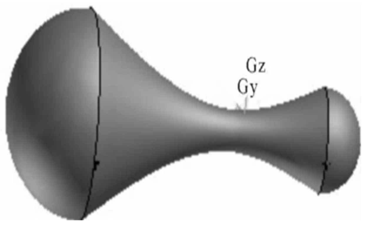
According to the basic theory of fluid mechanics, Lou Min [42] introduced a dog-bone device to suppress the vortex-induced vibration of marine risers, and the suppression effect of the device was tested by the ANSYS CFX 14.5 three-dimensional fluid–solid coupling method. The numerical simulation results show that the vibration suppression device not only effectively reduces the lateral vortex-induced vibration response, but also suppresses the longitudinal excitation, as shown in Figure 3.

Figure 3.
Dog-bone device (Gy and Gz are the Y-axis and Z-axis in the three-dimensional coordinate system, corresponding to vertical/height and depth/direction, respectively).
Ren Xiaohui [43] mentioned that a turbine-type vibration-suppression D energy capture device dynamically changes the flow field distribution around the riser, disrupts the formation of the shear layer, and the vortex shedding form of the wake destroys the normal discharge of the vortex, thereby weakening the vortex shedding intensity and reducing the force of vortex shedding on the deep-sea riser. By converting wave energy into rotational motion, the device disrupts wake vortices and suppresses riser vibrations.
3.2. Active Control Technology
Unlike passive vibration suppression techniques that rely on fixed devices, the active technology for suppressing a vortex-induced vibration is an ‘intelligent’ control system that requires an external energy input. The core idea of this technology is to monitor the vibration state of the structure or the pressure distribution of the flow field in real time through sensors, and then transmit these signals to the controller for processing. The controller calculates the optimal control instruction according to the preset control algorithm (such as feedback control) and finally drives the actuator (actuator) to intervene in the flow field or structure to offset or weaken the vortex-induced force. Common active vibration suppression techniques include using piezoelectric materials or servo motors to directly apply a reverse force or displacement to the structure; a synthetic jet or plasma actuator is arranged on the surface of the structure, and the boundary layer characteristics are changed by periodic blowing and suction, which interferes with the stable formation and shedding of the vortex, or by controlling the rotation of the structure (such as a cylinder) to change its flow characteristics. Active control technology has strong adaptability and remarkable control effects. It is especially suitable for occasions with variable flow conditions or extremely high requirements for vibration suppression. It is the frontier research direction in the field of fluid–solid coupling.
Ren Feng [44] constructed a closed-loop control loop with rotating excitation and wake velocity feedback as the core. Combined with the lattice Boltzmann method and the proximal strategy optimization algorithm, the amplitude of the cylinder was reduced by 89%. The proper orthogonal decomposition (POD) shows that intelligent control significantly changes the wake modal energy distribution.
Zou Lin [45] added velocity feedback and displacement feedback to the theoretical model of vortex-induced vibration and explored the control law of velocity feedback and displacement feedback. At the same time, he introduced an intelligent algorithm, used a neural network to map the flow field information to the feedback gain, and used a genetic algorithm to optimize the parameters of a neural network, so as to obtain the optimal combination of velocity feedback and displacement feedback under different reduced flow rates. Therefore, an enhancement strategy of cylindrical vortex-induced vibration is proposed, and then the active control of cylindrical vortex-induced vibration under different flow rates is realized. The results indicate that velocity and displacement feedback add energy to the system. This extra energy excites the cylinder’s vibration and vortex shedding. Consequently, the vibration starts sooner with feedback than without control. The vibration frequency also increases. Thus, the cylinder’s vortex shedding frequency breaks away from its natural frequency. Finally, the vibration amplitude ratio of the cylinder is stabilized within the target amplitude ratio (0.6–0.8) in the reduced velocity range. This result shows that the external excitation can control the vibration speed and start-up time of the structure. At the same time, the feedback gain constraint is introduced into the intelligent control algorithm model, and the original calculation model is further optimized, so that the average energy consumption, J, is reduced by 33.08% compared with the unconstrained case, which greatly reduces the energy consumption of the active control process.
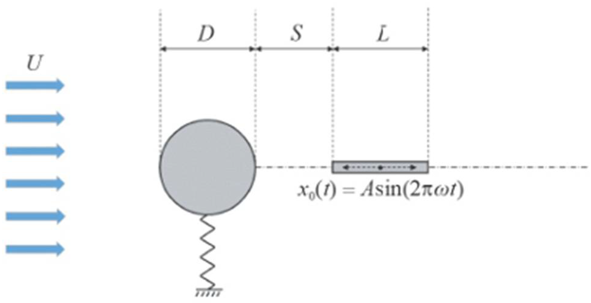
Ren [46] numerically simulated the active control of the cylinder VIV and proposed a wave-oscillating splitter plate as a control device for the dynamic response of the cylinder. The displacement response, lift–drag coefficient, cylinder vibration frequency, energy efficiency, and flow field characteristics of the control strategy were analyzed extensively, and the physical mechanism of the control system was revealed. The results show that in most cases, except for high deceleration speed, the displacement response of the cylinder can be limited to a small range by the control device without feedback. In addition, the control strategy can be changed by feedback control to maintain a better control effect at a high reduction speed. The oscillating splitter plate delays the vortex shedding of the shear layer generated on the cylinder, and the wake vortex with opposite rotation is parallel to the flow direction, which reduces their lateral distance. Therefore, due to the change in the flow pattern caused by the oscillating splitter plate, the lift on the cylinder is greatly reduced. The schematic diagram of the flow model is shown in Figure 4. In the diagram, a cylinder with a diameter of D = 0.01 m is immersed in a uniform flow at a flow rate of U, and the kinematic viscosity of the fluid is ν = 1 × 10 m2/s. A rectangular plate with an edge length L (equal to the diameter of the cylinder, L = D) and a thickness ratio of 0.1 is placed at a distance S from the trailing edge of the cylinder. The plate is forced to perform simple harmonic vibrations in the flow direction. The equation of the simple harmonic vibration is as follows: where A is the vibration amplitude, t is the forced vibration frequency of the plate, and the angular frequency is defined as ω = 2πf.

Figure 4.
Schematic diagram of the flow model.
Zhao Ming [47] proposed that the passive flow control device includes a splitter plate, control rod, spiral plate, porous layer, and rough surface, and the active flow control device includes a jet, rotating cylinder, and rotating control rod. A certain length of the splitter plate can inhibit VIV, but a too-long splitter plate will cause galloping. One or two control rods located downstream of the flow separation point can suppress VIV. VIV suppression using three to eight control rods was also studied. Increasing the number of control rods can improve the suppression effect. The porous layer with sufficient porosity and thickness can achieve almost complete VIV suppression and usually has better a suppression effect than the rough surface. When the pitch ratio of the spiral plate is greater than 10 and the height is greater than 0.2 times the cylindrical diameter, the VIV can be well suppressed. If sufficient external energy is used, jet control and rotating control rods can achieve almost complete VIV suppression. Rotating the control rod in one direction can suppress VIV, but rotating it in the other direction can enhance VIV.
The variable-diameter cylinder technology proposed by Raafat [48] realizes the dual-mode active control of vortex-induced vibration (VIV) by changing the outer diameter in real time through a built-in expansion pulley system, dynamically regulating the Reynolds number (Re) and the reduced flow velocity (Ur). The active tuning resonance in the energy harvesting mode expands the synchronization range by 70% and the power generation by more than 8 times. In the vibration suppression mode, the active detuning resonance weakens the vibration. This technology unified the energy collection and suppression function of VIV for the first time. The same system can intelligently switch modes according to the current conditions, collect energy for its self-power supply in the flat period, and suppress vibration and disaster prevention in the strong current period, which fundamentally solves the dual challenges of long-term energy supply and protection of underwater equipment.
Agathe [49] Schmider’s key research in 2024 proposed a ‘virtual spring-damping system’. This electromechanical integration device uses a computer-controlled DC motor to apply a force proportional to the riser’s speed and displacement, thereby equivalently generating adjustable virtual stiffness and virtual damping. This allows the system to adjust its natural frequency in real time according to the changing flow field conditions to avoid the resonance frequency of VIV. This is a typical semi-active control strategy.
3.3. Physical Model Experimental Technology
3.3.1. Design of Experimental Device
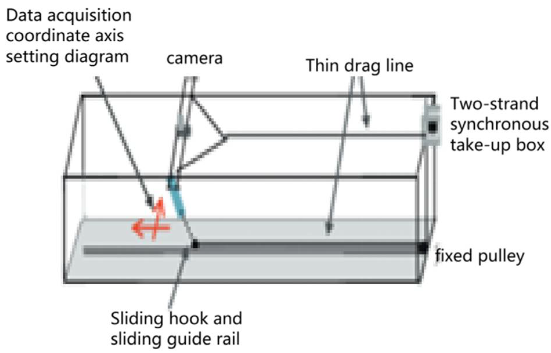
In terms of multi-degree-of-freedom coupling experiments, Lei Yusheng [50] adopted the following model experimental conditions: an empty d-center cylindrical buoy with a height of 10 cm and diameters of 2, 3, and 5 cm. The suspension line of the suspended cylindrical buoy was a soft nylon line with a length of 10 cm, and the uniform laminar flow (water, 20 °C) velocity range was from 5 cm/s to 25 cm/s. In addition, the range of Reynolds number Re (1.8 × 10³–8.1 × 10⁴) was obtained from the range of water flow velocity (drag velocity) and cylinder diameter used in the experiment. It can be seen that the experimental environment is basically in a typical subcritical state. The experimental scenario of vortex-induced motion is the motion of the bottom-hanging buoy under the uniform laminar impact environment. According to the basic principles of fluid mechanics, this uniform laminar flow state was difficult to obtain directly. Referring to the previous experimental experience and the principle of relative motion, the towing tank design was adopted. Compared with previous large-scale experiments, the uniqueness of this experiment is its small scale, low cost, and obvious results. The towing tank design and synchronous camera design used in this experiment have their own advantages compared with domestic large-scale devices. The device consisted of two parts: (1) Experimental environment device: coverless, transparent, glass box; bottom sliding guide rail; and pulley hook. The function of this part is to make the pulley, the hook, and the hollow cylindrical buoy hanging on it slide uniformly from one side of the water injection box to the other side with a fixed trajectory under the traction of the tractor. In this way, the scenario of uniform laminar flow impacting the bottom-mounted buoy was simulated equivalently. (2) Double constant-speed tractor and synchronous photography device: the main role is data acquisition. A micro-high-definition camera was fixed on the sliding frame and was towed at a constant speed by another towing line and the hook on the guide rail (an experimental cylindrical buoy was hung on the hook). At this time, the storage camera recorded the image directly below the synchronous sliding frame, thus realizing synchronous photography. Lei Yusheng’s specific experimental device diagram is shown in Figure 5.
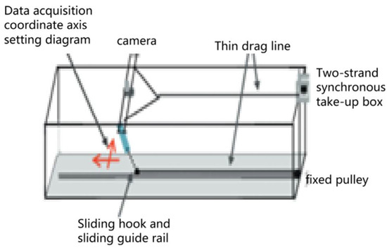
Figure 5.
Illustration of specific experimental device.
Based on the self-circulation experimental flume, Zhu Hongjun [51] carried out a vortex-induced vibration response test of a catenary flexible riser with platform surge and sway motion. The length–diameter ratio of the model riser was 125, and the average reduced velocity range of the test was 4.40–39.33. A laser displacement sensor and high-speed camera were used to monitor the platform motion and riser vibration displacement, respectively, and the influence of platform motion on the vibration of the riser was analyzed from the aspects of response frequency, amplitude, and vibration form. The experiment was carried out in the self-circulation experimental flume of Southwest Petroleum University. The flume test section was 2 m (length) × 0.5 m (width) × 1 m (height), and the experimental water depth was 0.65 m. A generalized model was used in the experiment. The transparent silicone tube with an outer diameter of D = 8 mm (wall thickness 1 mm) was selected as the flexible riser model, and the length–diameter ratio L/D = 125 was arranged in the flume test section in a catenary shape. The bottom was fixed to the bottom wall of the flume, the top was hinged at the bottom of the platform, and the riser was concave. The vertical height was h = 0.65 m. The riser was completely immersed in water, and the lateral blocking rate was 1.6%, which met the critical blocking rate requirement of less than 5%. The experimental tank is shown in Figure 6.

Figure 6.
Schematic diagram of the cyclic experimental tank.
3.3.2. Measurement and Visualization Techniques
The measurement and visualization technology of the vortex-induced vibration of flexible risers is the core method to study the dynamic response of risers in deep-sea engineering. The technology realizes real-time monitoring and full-field visualization of the strain, displacement, and wake vortex structure of the riser in the complex flow field by means of a fiber grating sensor, digital image correlation (DIC) technology, and high-speed camera. The experiment usually simulates the deep-sea environment in the flume and studies its multi-modal response characteristics under vortex-induced vibration by adjusting the flow velocity, flow field distribution (such as uniform flow, shear flow), and riser parameters (slenderness ratio, pre-tension). Combined with numerical simulation and experimental data, this technology can reveal the fatigue damage mechanism of risers and provide key support for deep-sea pipeline designs and safety assessments.
Lyons et al.’s [52] measurement technology (on-site monitoring-FUMS system) used a novel curvature-sensing element to measure the bending stress of submarine umbilical cables. A load sensor was installed at the top of the umbilical cable to measure the tension. Data analysis: The new method was used to identify the contribution of different frequency components (mooring system, wave, and vortex-induced vibration) to excitation, and the rain-flow counting method was used to evaluate fatigue life. Main contributions: High-quality VIV data from real operating environments are provided, revealing the increase in the drag coefficient caused by VIV, and providing insights into the contribution of different excitation sources to fatigue damage.
According to Chaplin et al. [53], an experimental study was conducted on a top-tensioned aluminum-core riser model (covered with a fluorine-containing plastic tube) to measure its VIV response under stepped flow and different tension conditions, and to identify vibration modes. Such experiments use strain gauges or accelerometers. Experimental data of the VIV response of flexible risers under specific conditions are provided, which are often used to compare other numerical models or experimental results.
This study was proposed by Seyed-Aghazadeh [54] to investigate the flow-induced vibration (FIV) characteristics of flexible cylinders with triangular cross-sections at different angles of attack and reduced velocities (0.9–16.27, corresponding to Reynolds number 364–3600) through water tunnel experiments, including transverse, in-line, and torsional vibrations. The three-dimensional vibration (cross flow, downstream flow, and torsion) of the flexible triangular cylinder is recorded by motion tracking technology. Although the details of the specific camera and marker system are not detailed in the abstract, this study highlights the significant effects of torsional oscillation, spanwise flexibility, and fixed boundary conditions on the response. Hydrogen-bubble flow visualization technique was used to qualitatively observe the wake field of the cylinder to preliminarily understand the shape and shedding mode of the vortex.
Gao et al.’s research [55] aims to experimentally explore the influence of gas–liquid two-phase slug flow on the vibration response of a catenary flexible riser. The core requirement is to synchronously and non-invasively capture the vibration displacement details of the riser and the flow pattern characteristics of the slug flow inside the pipeline (such as liquid slug length and pressure pulsation) and to study the effects of two key flow parameters, gas–liquid mixing speed and gas–liquid ratio, on the vibration response of the flexible riser. A high-speed camera system is used to capture synchronous, non-invasive visualizations of the vibration displacement of the riser and the characteristics of internal slug flow (such as liquid slug length and aeroelastic shape).
4. Challenges and Prospective Studies
As the global energy demand extends to the deep sea, the structural safety and integrity of marine risers, such as the key ‘lifeline’ connecting the subsea wellhead and the floating platform, are facing unprecedented challenges. VIV is a typical nonlinear fluid–solid coupling phenomenon. Its complex physical mechanism and potentially destructive consequences make it a long-term research hotspot and a difficult design in the field of marine engineering.
4.1. Challenges
4.1.1. The Uncertainty of the Predicted Dilemma Model
Despite decades of in-depth research, the accurate and reliable prediction of riser VIV is still one of the most challenging tasks in marine engineering. The inherent limitations of the prediction model and the scale difference between the experimental data and the real working conditions together constitute an insurmountable ‘prediction dilemma’. This uncertainty directly leads to conservatism in engineering design and triggers a series of interlocking economic and technical problems. Table 2 below compares the different models.
Table 2.
Comparative analysis of riser VIV prediction methods.
4.1.2. Inhibition Technology: From Passive Intervention to Active Control
The passive system permanently interferes with the vortex-shedding process by changing the geometric shape or hydrodynamic characteristics of the riser. The active/semi-active system uses intelligent materials and control algorithms to sense and offset vibrations in real time. The evolution of technology clearly shows the trend from ‘violent intervention’ to ‘smart control’.
- (1)
- Passive suppression system: trade-off between efficiency and cost
Increasing the fin height can significantly enhance the vibration suppression effect, while changing the pitch will affect the range of the ‘lock-in’ zone. Under the optimized design, the vibration suppression efficiency can reach more than 90%. However, the greatest disadvantage of a helical strake is its large size.
Fairings provide another efficient solution. Different from the ‘destruction’ mechanism of the plate, the guide cover adopts the ‘dredging’ strategy. Its streamlined shell can guide water flow smoothly around the riser, fundamentally avoiding the formation and shedding of strong vortices. The shroud is designed to rotate freely around the riser so that its tail can automatically align with the incoming flow direction and always maintain the best streamlined shape. The vibration suppression effect of the diversion cover is excellent and is considered to be ‘unparalleled’. Its biggest advantage is that it not only does not increase the drag force but can be significant.
- (2)
- Active and semi-active control: application of smart materials
Active control: The system uses an external power supply to apply a control force that is opposite to the vibration velocity or displacement through an actuator (such as a piezoelectric plate), thereby actively offsetting or suppressing vibration. This method has strong adaptability and a good effect, but the system is complex, energy consumption is high, and the cost is high.
Semi-active/passive shunt damping: This is a potential compromise. It connects the piezoelectric plate to an external electronic ‘shunt’ circuit (such as a simple RLC circuit). When the structure vibrates, the electric energy generated by the piezoelectric sheet will be dissipated in the shunt circuit (usually in the form of heat energy), thus equivalently providing adjustable additional damping to the structure. This method does not require a large external power supply and has the simplicity of a passive system and the tunability of an active system.
At present, the application of active and semi-active control technology in the field of the VIV suppression of risers is still mainly in the laboratory research stage. To promote it to engineering applications, many challenges need to be overcome, including the development of robust control algorithms for complex fluid–solid coupling problems, ensuring the long-term reliability of the system in harsh marine environments, and how to scale up the application of technology to large marine structures.
Early helical strakes permanently disrupt flow to suppress vibration but always create high drag. The hood passively adapts to flow conditions, cooperating rather than conflicting with the flow. Future active/semi-active systems will deliver intelligent vibration control. They no longer permanently transform the structure, but precisely apply the control force when and where it is needed. The core objective of energy regenerative damping is to maximize energy recovery efficiency. It transforms the problem itself (vibration energy) into a part of the solution (control system power supply), indicating the high intelligence and high efficiency of VIV suppression technology in the future. Behind this evolution is the high cost and secondary problems of traditional methods, as well as the continuous maturity of enabling technologies, such as intelligent materials and control theory.
4.2. Prospect
In the face of the continuous challenges of VIV prediction and suppression, the marine engineering community is ushering in a profound paradigm change. The future development direction is no longer limited to the improvement of a single prediction model or vibration suppression device, but rather to a lifecycle ‘intelligent riser integrity management’ framework that integrates advanced sensing, artificial intelligence, and system modeling. The core of this transformation is to move from a static and conservative design concept to a dynamic and intelligent operation and management model, replacing the conservatism based on assumptions and experience with real-time and data-driven insights, which is expected to greatly optimize operational efficiency and lifecycle costs while ensuring or even improving safety.
This paradigm shift from a ‘static design’ to ‘dynamic management’ highlights the direction for future research. Firstly, it is necessary to develop a hybrid prediction model that can integrate the speed of semi-empirical methods, the accuracy of CFD, and the learning ability of AI to perform fast and accurate engineering decisions. Secondly, we should continue to promote the development of advanced suppression technologies, including new low-resistance passive devices and active/semi-active control systems based on smart materials from laboratory to application. At the same time, in order to ensure the reliable application of AI in safety-critical systems, it is very important to establish a standardized verification and certification process for AI models. Finally, it is necessary to deepen the research on the mechanism of multi-physical field coupling effects, such as VIV and platform motion, internal multiphase flow, and seabed interaction, so as to lay a foundation for higher-level prediction and control.
5. Conclusions
The vortex-induced vibration (VIV) of flexible risers in ocean engineering is a comprehensive subject involving complex physical mechanisms, diverse engineering practices, and frontier scientific exploration. As a core issue directly related to the structural integrity and service life of risers, the in-depth understanding, accurate prediction, and effective suppression of VIVs are always the key links to ensure the safety of deep-sea energy development. Although the industry has accumulated rich experience in suppression technology and prediction models, there are still profound challenges and broad exploration space in this field. The main conclusions and prospects of this paper are summarized as follows:
(1) Complex coupling of influencing factors: Vortex-induced vibration (VIV) of flexible risers is a complex fluid–solid coupling phenomenon driven by multiple factors. Its response characteristics not only depend on the structural parameters of the riser itself (such as slenderness ratio, mass ratio, top tension, damping, surface roughness, etc.), but also are significantly affected by external flow field conditions (such as incoming flow velocity, velocity profile, wave action, etc.) and possible platform motion coupling effects. These factors work together to create complex dynamic behaviors, such as multi-modal excitation, broadband characteristics, and the coexistence of traveling waves and standing waves in riser VIV responses, which makes the accurate prediction and comprehensive understanding of VIV extremely challenging.
(2) Diversity and trade-off of suppression strategies: For the vortex-induced vibration of flexible risers, the current engineering field mainly relies on passive suppression devices. While spiral plates are widely used due to their reliable vibration suppression effect, they increase structural drag force as a relative drawback. Other additional accessories, such as deflectors/fairings, separation plates, and new spiral grooves, as well as design-level strategies, such as optimizing riser configurations (such as inert wave risers) and adjusting top tension, have also been adopted to reduce VIV. Due to its complexity and the reliability challenges of underwater applications, the active control method is rarely used in practical engineering. The selection of the suppression strategy should take into account the effect of vibration suppression, economic cost, convenience of installation and maintenance, and the impact on other hydrodynamic factors (such as additional resistance).
(3) Cross-driven research bottlenecks and prospects: the VIV research on flexible risers still faces many bottlenecks, including the accurate prediction of VIV responses under high Reynolds number and complex flow fields (such as shear flow), the lack of full-scale experimental data, and the extrapolation of experimental results to practical engineering, as well as the limitations and computational costs of existing numerical models (whether semi-empirical models or CFD) in capturing three-dimensional effects and fluid–solid coupling complexity. Future research trends will focus more on the development of high-fidelity numerical simulation methods (such as improved CFD technology and finer fluid–solid coupling algorithms), more refined experimental measurements (such as advanced flow field display technology and distributed sensing technology), and full-scale in-service monitoring, as well as the integration of advanced data analysis tools, such as artificial intelligence and machine learning, for pattern recognition and surrogate model construction, to reveal the VIV mechanism more deeply, improve prediction accuracy, and develop more efficient and economical suppression techniques.
In summary, vortex-induced vibration is a core and complex challenge in the field of fluid–solid coupling. Its effective suppression is the cornerstone to ensure the safety and reliability of various engineering structures, especially key equipment, such as marine flexible risers, throughout their lifecycle. From general passive control devices, such as helical strakes and shrouds, to system configuration optimization for flexible risers (such as lazy waveform designs), an effective suppression strategy system has been developed in the engineering community. The core of these methods is to destroy the regularity of vortex shedding by changing the hydrodynamic shape or system dynamics characteristics of the structure, so as to avoid its potential destructive force. Practice has proved that there is no universal ‘best’ solution. The choice of vortex vibration suppression strategy is a comprehensive decision that is highly dependent on engineering experience. It requires designers to conduct a comprehensive and prudent assessment of structural characteristics, environmental conditions, economic costs, and safety risks. Looking forward to the future, as the project moves toward addressing a deeper and harsher environment, the continuous optimization and innovation of vortex-induced vibration suppression technology will still be an indispensable part of ensuring project safety.
Author Contributions
Conceptualization, C.Y. and Q.F.; methodology, C.Y.; software, S.Y.; validation, C.Y., Q.F. and S.Y.; formal analysis, Q.F.; investigation, S.Y.; resources, S.Y.; data curation, C.Y.; writing—original draft preparation, Q.F.; writing—review and editing, S.Y.; visualization, C.Y.; supervision, S.Y.; All authors have read and agreed to the published version of the manuscript.
Funding
This research received no external funding.
Data Availability Statement
The original contributions presented in this study are included in the article. Further inquiries can be directed to the corresponding author(s).
Conflicts of Interest
The authors declare conflicts of interest.
References
- Pan, Z.Y.; Cui, W.C.; Zhang, X.C. Overview on VIV of Slender Marine Structures. J. Ship Mech. 2005, 9, 135–154. [Google Scholar]
- Hong, K.; Shah, U.H. Vortex-Induced Vibrations and Control of Marine Risers: A Review. Ocean Eng. 2018, 152, 300–315. [Google Scholar] [CrossRef]
- Teng, B. Experimental Study on Vortex-Induced Vibration of Slender Flexible Risers. Ph.D. Thesis, Dalian University of Technology, Dalian, China, 2009. [Google Scholar]
- Vandiver, J.K. Dimensionless Parameters Important in the Prediction of Vortex-Induced Vibration of Long, Flexible Cylinders in Ocean Currents. J. Fluids Struct. 1983, 3, 423–455. [Google Scholar] [CrossRef]
- Wang, C.; Zheng, R.; Li, M. A Review of Basic Theories, Research Methods, Influencing Factors, and Vibration Suppression Methods for Vortex-Induced Vibration of Marine Risers. J. Shandong Univ. Technol. Nat. Sci. Ed. 2024, 38, 1–7. [Google Scholar]
- Feng, C.C. The Measurement of Vortex Induced Effects in Flow Past Stationary and Oscillating Circular and D-Section Cylinders. Ph.D. Thesis, University of British Columbia, Vancouver, BC, Canada, 1968. [Google Scholar]
- Sarpkaya, T. Fluid Forces on Oscillating Cylinders. J. Waterw. Port Coast. Ocean Div. 1978, 104, 275–290. [Google Scholar] [CrossRef]
- Khalak, A.; Williamson, C.H.K. Dynamics of a Hydroelastic Cylinder with Very Low Mass and Damping. J. Fluids Struct. 1996, 10, 455–472. [Google Scholar] [CrossRef]
- Govardhan, R.; Williamson, C.H.K. Modes of Vortex Formation and Frequency Response of a Freely Vibrating Cylinder. J. Fluid Mech. 2000, 420, 85–130. [Google Scholar] [CrossRef]
- Hartlen, R.T.; Currie, I.G. Lift-Oscillator Model of Vortex-Induced Vibration. J. Eng. Mech. Div. 1970, 96, 577–591. [Google Scholar] [CrossRef]
- Skop, R.A.; Griffin, O.M. A Model for the Vortex-Excited Resonant Response of Bluff Cylinders. J. Sound Vib. 1973, 27, 225–233. [Google Scholar] [CrossRef]
- Guo, H.Y.; Wang, S.Q.; Wu, J.N.; Liu, D.F. Dynamic Characteristics of Marine Risers Conveying Fluid. China Ocean Eng. 2000, 14, 153–160. [Google Scholar] [CrossRef]
- Stansby, P.K.; Slaouti, A. Simulation of Vortex Shedding Including Blockage by the Random—Vortex and Other Methods. Int. J. Numer. Methods Fluids 1993, 17, 1003–1013. [Google Scholar] [CrossRef]
- Huera-Huarte, F. Vortex-Induced Vibration of Flexible Cylinders in Cross-Flow. Annu. Rev. Fluid Mech. 2025, 57, 285–310. [Google Scholar] [CrossRef]
- Wan, D.; Duan, M. Advances in Numerical Analysis Methods for Vortex-Induced Vibration of Slender Flexible Risers in Deep Sea. Mech. Q 2017, 38, 179–196. [Google Scholar]
- Gao, W.; Fu, S.; Chen, Y. Review on Fluid-Solid Coupling and Dynamic Response of Vortex-Induced Vibration of Slender Ocean Cylinders. Adv. Mech. 2017, 47, 25–91. [Google Scholar]
- Evangelinos, C.; Lucor, D.; Karniadakis, G.E. DNS-Derived Force Distribution on Flexible Cylinders Subject to Vortex-Induced Vibration. J. Fluids Struct. 2000, 14, 429–440. [Google Scholar] [CrossRef]
- Zhang, J. Experimental Investigation of Vortex-Induced Vibration of Long-Flexible Marine Risers. Ph.D. Thesis, Dalian University of Technology, Dalian, China, 2009. [Google Scholar]
- Duan, M. Development of Computer Code for Vortex-Induced Vibration of Long Flexible Riser and Its Applications. Ph.D. Thesis, Shanghai Jiao Tong University, Shanghai, China, 2017. [Google Scholar]
- Li, P.; Guo, H.Y.; Liu, J.W.; Zhang, Y.B. Experimental Study on Sensibility of VIV Suppression of Deep-sea Risers with Large Slenderness Ratio in a Stepped Current. J. Shandong Univ. Sci. Technol. Nat. Sci. Ed. 2015, 34, 93–101. [Google Scholar] [CrossRef]
- Li, M.; Dun, D.; Wan, D. Numerical Simulation of Vortex-Induced Vibration of Slender Flexible Riser with Additional Baffles. J. Hydrodyn. 2021, 36, 112–120. [Google Scholar] [CrossRef]
- Song, J.N.; Li, Z.; Jiang, X.L.; Jin, R.J.; Liu, Y.H. Effect of Mass Ratio on Flow-Induced Vibration of D-Shaped Cross-Section Cylinder. Acta Mech. Sin. 2024, 56, 540–549. [Google Scholar]
- Khalilpasha, H.; Albermani, F. Textured Deep Subsea Pipelines. Int. J. Mech. Sci. 2013, 68, 224–235. [Google Scholar] [CrossRef]
- Nikoo, H.M.; Bi, K.; Hao, H. Textured Pipe-in-Pipe System: A Compound Passive Technique for Vortex-Induced Vibration Control. Appl. Ocean Res. 2020, 95, 102044. [Google Scholar] [CrossRef]
- Liu, X.H.; Wang, Y.X.; Wang, G.Y. Influence of Parameters of Wing Spoiler on Hydrodynamic Characteristics of Submarine Pipeline. Ship Ocean Eng. 2013, 42, 169–173. [Google Scholar]
- Yu, S.H.; Feng, B.; Fan, Y.Z.; Fu, M.L.; Yu, X. Numerical Analysis of Vortex-induced Vibration Response of Suspended Span Submarine Cable. High Volt. Eng. 2024, 50, 4101–4109. [Google Scholar] [CrossRef]
- Duan, J.; Zhou, J.; Wang, X.; Chen, K. Cross-Flow Vortex-Induced Vibration of a Flexible Riser with Internal Flow in Shear Current. J. Mech. 2021, 53, 1876–1884. [Google Scholar]
- Ma, Y. Study on the Characteristics and Suppression of Vortex-Inducedvibration of Marine Riser Under Inclined Flow Andtime-Varying Axial Force. Ph.D. Thesis, Tianjin University, Tianjin, China, 2022. [Google Scholar] [CrossRef]
- Li, X.; Wang, Y.Y.; Zhu, X.P.; Qu, Y.H. Effect of Incoming Flow Angle on Flow-Induced Vibration of Square Cylinder. Ship Sci. Technol. 2024, 46, 27–33. [Google Scholar]
- Duan, J.; Zhou, J.; You, Y.; Wang, X. Effect of Internal Flow on Vortex-Induced Vibration Dynamics of a Flexible Mining Riser in External Shear Current. Mar. Struct. 2021, 80, 103094. [Google Scholar] [CrossRef]
- Holzner, M.; Guala, M.; Lüthi, B.; Liberzon, A.; Nikitin, N.; Kinzelbach, W.; Tsinober, A. Viscous Tilting and Production of Vorticity in Homogeneous Turbulence. Phys. Fluids 2010, 22, 061701. [Google Scholar] [CrossRef]
- Senga, H.; Larsen, C.M. Forced Motion Experiments Using Cylinders with Helical Strakes. J. Fluids Struct. 2017, 68, 279–294. [Google Scholar] [CrossRef]
- Zhu, H.; Liao, Z.; Gao, Y.; Zhao, Y. Numerical Evaluation of the Suppression Effect of a Free-to-Rotate Triangular Fairing on the Vortex-Induced Vibration of a Circular Cylinder. Appl. Math. Model. 2017, 52, 709–730. [Google Scholar] [CrossRef]
- Wang, W.; Song, B.; Mao, Z.; Tian, W.; Zhang, T. Numerical Investigation on VIV Suppression of Marine Risers Attached with Rotating Wings. J. Ship Mech. 2021, 25, 29–36. [Google Scholar]
- Quen, L.K.; Abu, A.; Kato, N.; Muhamad, P.; Tan, L.K.; Kang, H.S. Performance of Two- and Three-Start Helical Strakes in Suppressing the Vortex-Induced Vibration of a Low Mass Ratio Flexible Cylinder. Ocean Eng. 2018, 166, 253–261. [Google Scholar] [CrossRef]
- Gao, Y.; Fu, S.; Ren, T.; Xiong, Y.; Song, L. VIV Response of a Long Flexible Riser Fitted with Strakes in Uniform and Linearly Sheared Currents. Appl. Ocean Res. 2015, 52, 102–114. [Google Scholar] [CrossRef]
- Xu, W.; Luan, Y.; Liu, L.; Wu, Y. Influences of the Helical Strake Cross-Section Shape on Vortex-Induced Vibrations Suppression for a Long Flexible Cylinder. China Ocean Eng. 2017, 31, 438–446. [Google Scholar] [CrossRef]
- Ma, Y.; Xu, W.; Ai, H.; Wang, Y.; Jia, K. The Effect of Time-Varying Axial Tension on VIV Suppression for a Flexible Cylinder Attached with Helical Strakes. Ocean Eng. 2021, 241, 109981. [Google Scholar] [CrossRef]
- Xu, W.; Luan, Y.; Han, Q.; Ji, C.; Cheng, A. The Effect of Yaw Angle on VIV Suppression for an Inclined Flexible Cylinder Fitted with Helical Strakes. Appl. Ocean Res. 2017, 67, 263–276. [Google Scholar] [CrossRef]
- Lu, Y.; Liao, Y.; Liu, B.; Xu, W. Cross-Flow Vortex-Induced Vibration Reduction of a Long Flexible Cylinder Using 3 and 4 Control Rods with Different Configurations. Appl. Ocean Res. 2019, 91, 101900. [Google Scholar] [CrossRef]
- Xu, W.H.; Qin, W.Q.; Lu, Y. Application of Control Rods for Passively Suppressing Cross-Flow VIV of an Inclined Flexible Cylinder. Shock Vib. 2018, 2018, 8365726. [Google Scholar] [CrossRef]
- Lou, M.; Yu, C.; Dong, W. Numerical Simulation of VIV Control on Marine Riser with Dog Bones. Ship Ocean Eng. 2013, 42, 147–151. [Google Scholar]
- Ren, X.H.; Li, P.; Wang, C.Z.; Liu, Z.; Chen, X.; Lou, M.; Zhu, L.; Wang, Y.S.; Huang, Y.J. Experimental Study on Vibration Suppression-Energy Harvesting Device for Marine Risers. J. Shandong Univ. Sci. Technol. Nat. Sci. 2023, 42, 53–62. [Google Scholar] [CrossRef]
- Ren, F. Intelligent Flow Control for Vortex-Induced Vibration of Cylinder. J. Hydrodyn. 2022, 37, 757–762. [Google Scholar] [CrossRef]
- Zou, L.; Wang, C.; Zheng, Y.L.; Xu, J.L. Active Control of Vortex-Induced Vibration of Cylinder Based on Velocity and Displacement Feedback. Acta Mech. Sin. 2023, 55, 1834–1846. [Google Scholar]
- Ren, Y.; Xin, Z.; Gu, S. Active Control of Vortex-Induced Vibration of a Circular Cylinder by Using the Oscillatory Plate Immersed in the Cylinder Wake at Low Reynolds Number. Acta Mech. Sin. 2022, 38, 321530. [Google Scholar] [CrossRef]
- Zhao, M. A Review of Recent Studies on the Control of Vortex-Induced Vibration of Circular Cylinders. Ocean Eng. 2023, 285, 115389. [Google Scholar] [CrossRef]
- Raafat, A.; Kamra, M.; Al Nuaimi, S. Vortex Induced Vibration of a Deformable Cylinder for Wide Lock-In Range Energy Harvesting. Eng. Appl. Comput. Fluid Mech. 2025, 19, 2514654. [Google Scholar] [CrossRef]
- Schnider, A.; Kerhervé, F.; Spohn, A.; Cordier, L. Improved VIV Energy Harvesting with a Virtual Damper-Spring System. Ocean Eng. 2024, 293, 116668. [Google Scholar] [CrossRef]
- Lei, Y.S.; Li, X.T.; Ding, J.; Liu, W.; Shi, Q.F. Design of a Research Experiment of Vortex-Induced Motion. Phys. Eng. 2019, 29, 74–80, 85. [Google Scholar]
- Zhu, H.; Liu, W.; Gao, Y. Experimental Study of the Influence of Platform Motion on the Vortex-Induced Vibration of a Flexible Riser. J. Mech. 2024, 56, 565–576. [Google Scholar]
- Lyons, G.J.; Vandiver, J.K.; Larsen, C.M.; Ashcombe, G.T. Vortex-Induced Vibrations Measured in Service in the Foinaven Dynamic Umbilical, and Lessons from Prediction. J. Fluids Struct. 2003, 17, 1079–1094. [Google Scholar] [CrossRef]
- Chaplin, J.R.; Bearman, P.W.; Huera Huarte, F.J.; Pattenden, R.J. Laboratory Measurements of Vortex-Induced Vibrations of a Vertical Tension Riser in a Stepped Current. J. Fluids Struct. 2005, 21, 3–24. [Google Scholar] [CrossRef]
- Seyed-Aghazadeh, B.; Mousavisani, S.; Samandari, H. Experimental Investigation of Flow-Induced Vibration and Flow Field Characteristics of a Flexible Triangular Cylinder. J. Fluid Mech. 2024, 979, A15. [Google Scholar] [CrossRef]
- Gao, Y.; Hu, J.; Zhu, H. Severe Slug Flow-Induced Nonlinear Dynamic Behavior of a Flexible Catenary Riser. Phys. Fluids 2021, 33, 071705. [Google Scholar] [CrossRef]


Disclaimer/Publisher’s Note: The statements, opinions and data contained in all publications are solely those of the individual author(s) and contributor(s) and not of MDPI and/or the editor(s). MDPI and/or the editor(s) disclaim responsibility for any injury to people or property resulting from any ideas, methods, instructions or products referred to in the content. |
© 2025 by the authors. Licensee MDPI, Basel, Switzerland. This article is an open access article distributed under the terms and conditions of the Creative Commons Attribution (CC BY) license (https://creativecommons.org/licenses/by/4.0/).