
Analysis of Flow Field and Machining Parameters in RUREMM for High-Precision Micro-Texture Fabrication on SS304 Surfaces


Abstract
1. Introduction
2. Principle of the RUREMM
3. Theoretical Design
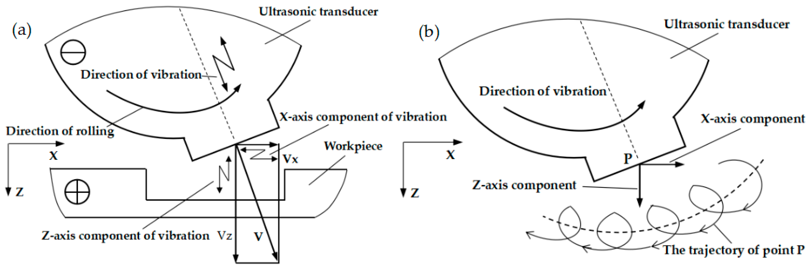
Motion Patterns of RUREMM Machining
4. Simulation Design
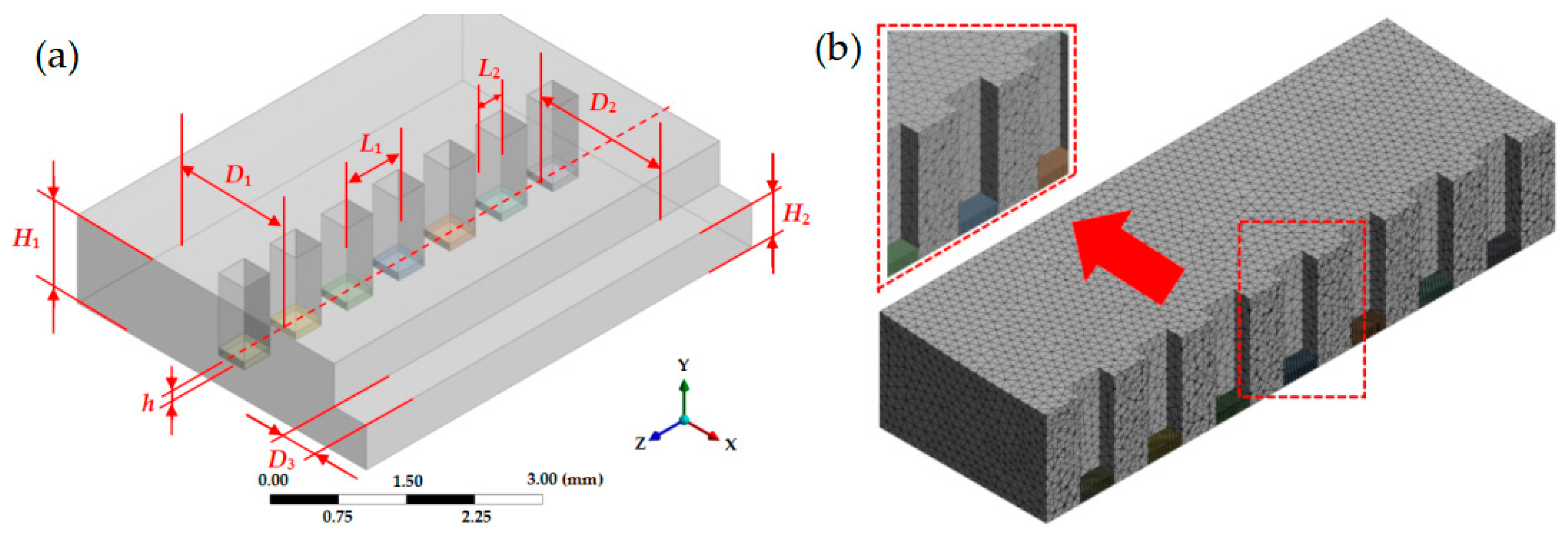
4.1. Model Description
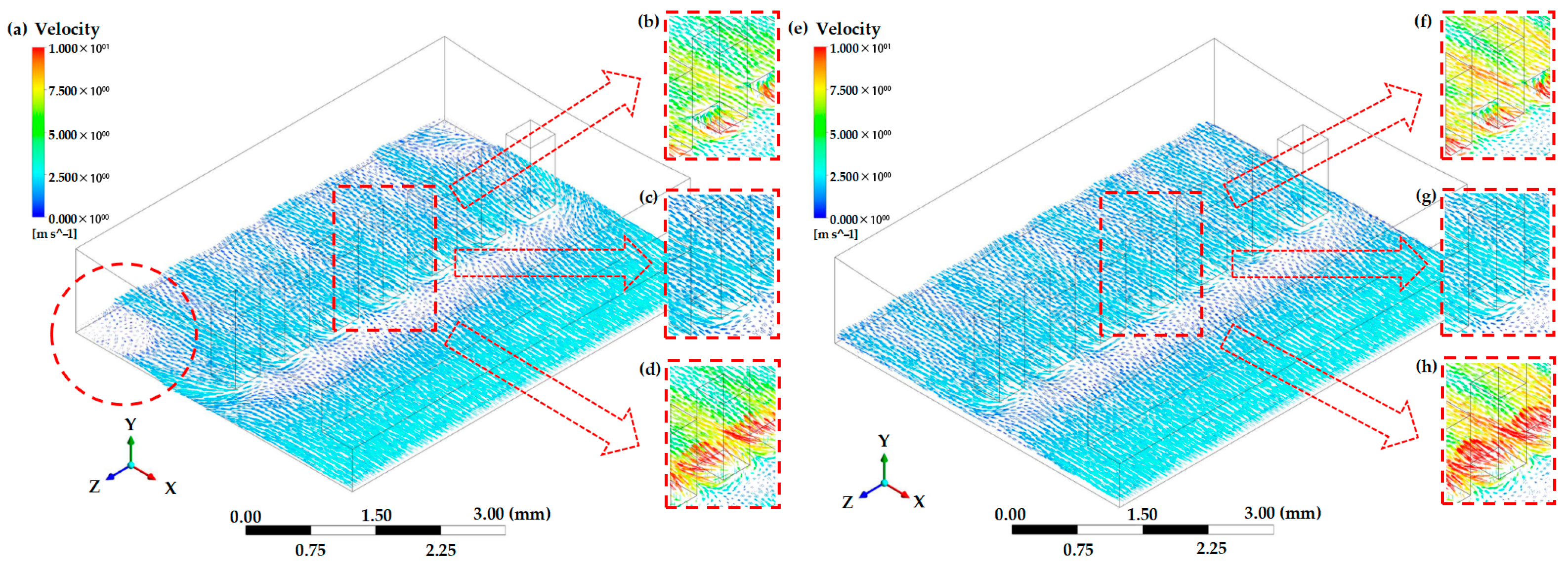
4.2. Simulation Analysis
5. Experimental Design
5.1. Experimental Equipment
5.2. Experimental Setup
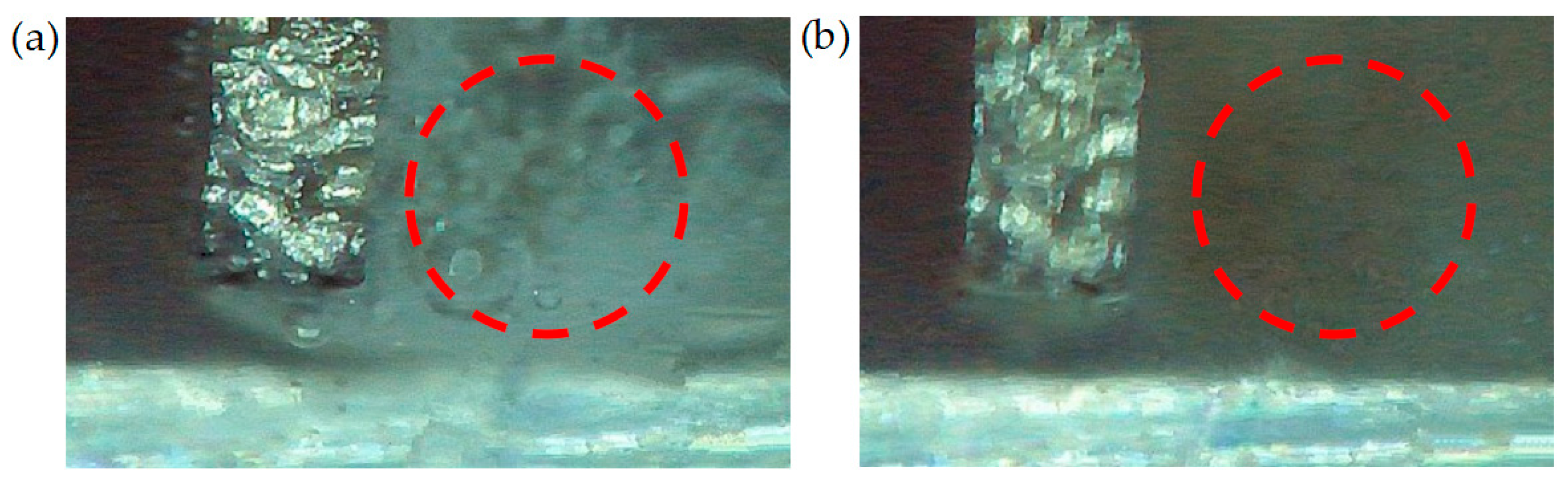
5.3. Experiment on Bubble Observation
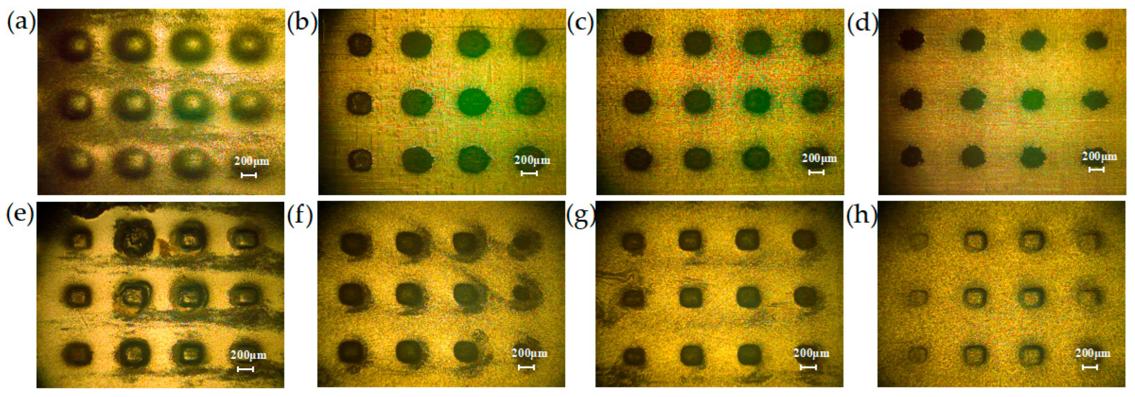
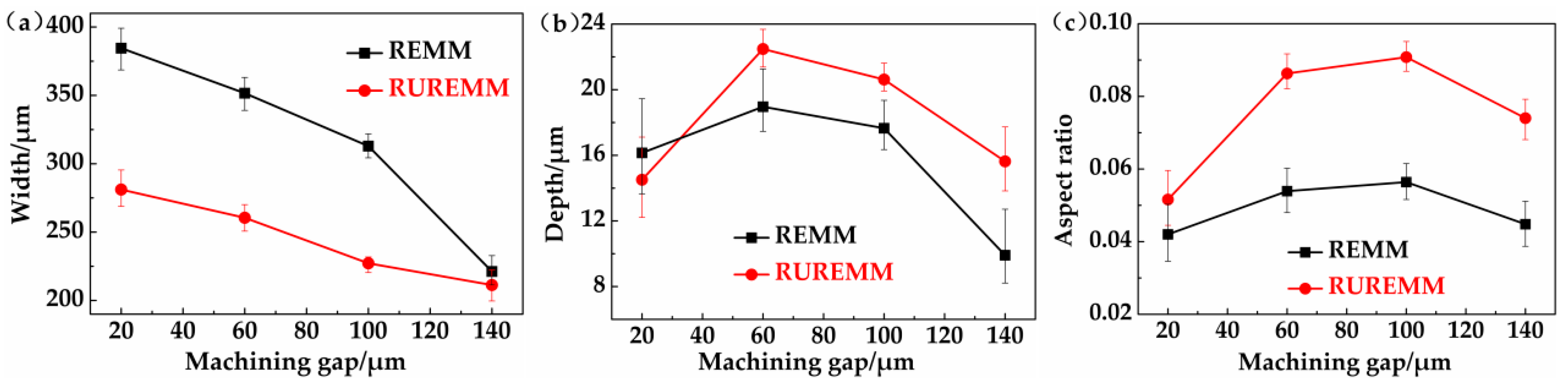
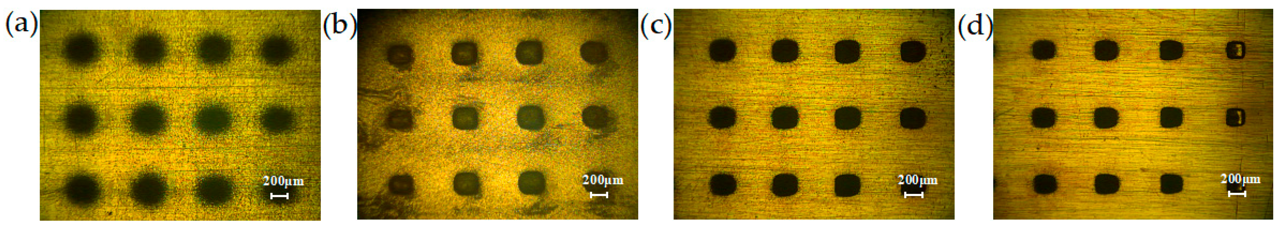
5.4. Effect of Different Machining Parameters
6. Conclusions
- (1)
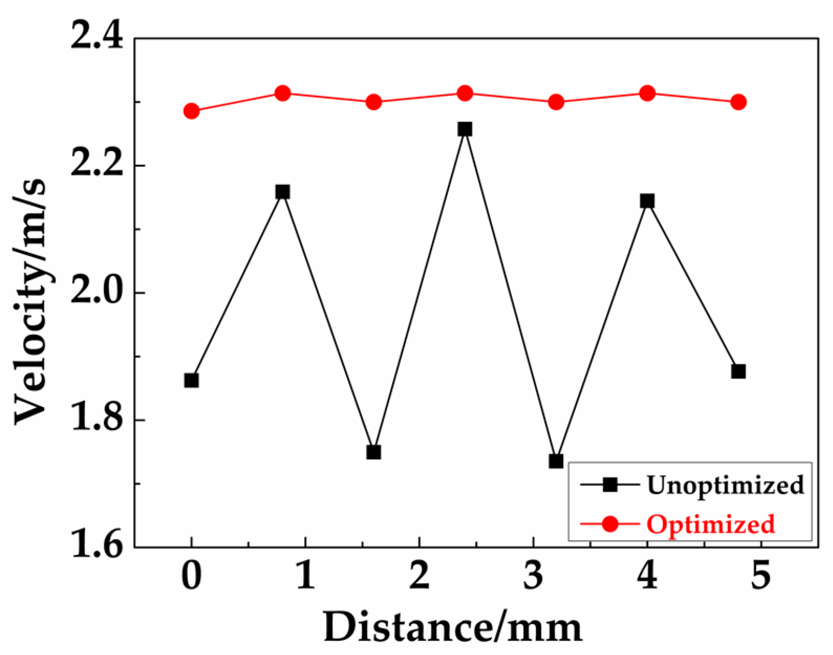
- A theoretical model was developed to quantify ultrasonic-electrochemical coupling in rotary ultrasonic-assisted reverse electrochemical machining (RUREMM). CFD simulations demonstrated sidewall shielding optimized electrolyte flow homogeneity, achieving laminar stability at 4 m/s and 35 μm. Critical parameters for minimizing machining fluctuations were identified. Future work includes multi-physics modeling with thermal stress effects, AI-driven adaptive control, and nano-electrolyte integration to enhance material removal. Applications span aerospace turbine blade fabrication, medical implant surface engineering, and microelectronics via drilling, addressing precision manufacturing needs for advanced materials with a reduced environmental footprint.
- (2)
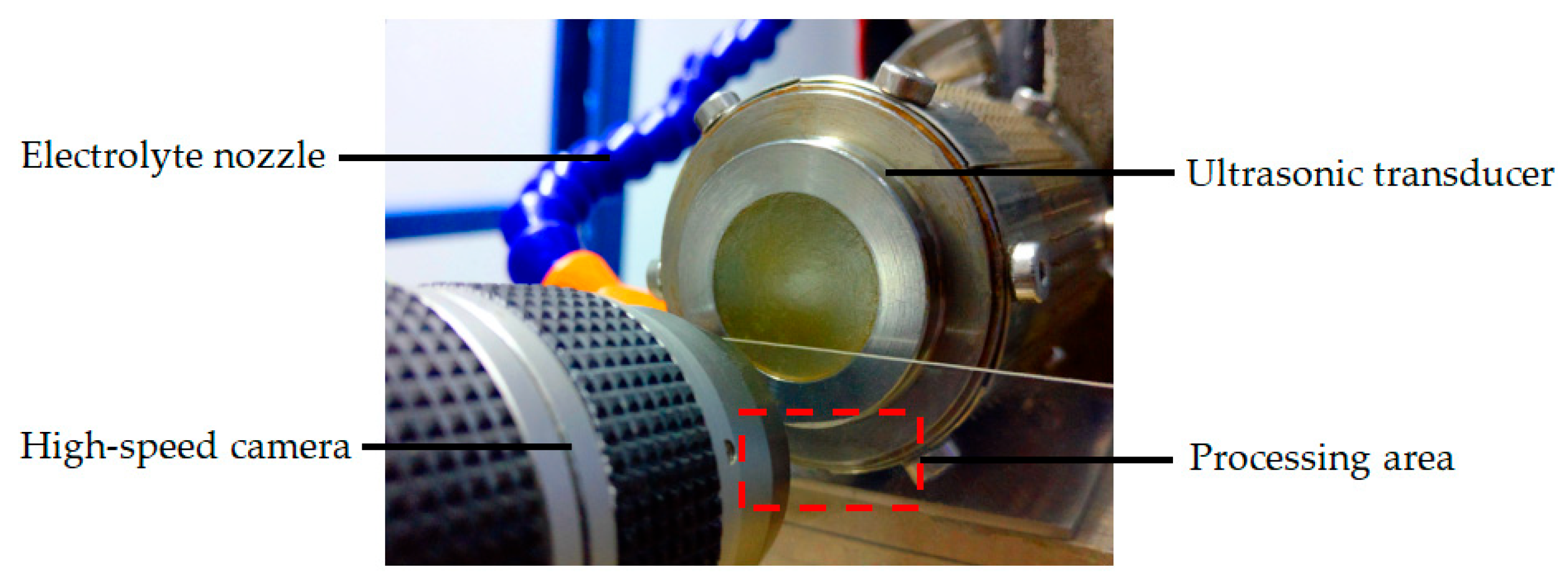
- High-speed imaging of machining gap bubble dynamics revealed ultrasonic suppression of coalescence, reducing cluster size, while cavitation-induced micro-jets modulated flow field behavior. CFD modeling validated optimal parameters at 20 kHz, 35 μm amplitude, and 4 m/s electrolyte flow. Future work focuses on multi-physics integration of bubble-electrochemical interactions, AI-driven real-time monitoring systems, and nano-electrolyte formulations to enhance cavitation efficiency. Applications include aerospace titanium alloy finishing, medical implant surface microstructuring, and semiconductor precision etching, addressing sub-μm precision demands in advanced manufacturing via ultrasonic cavitation control.
- (3)
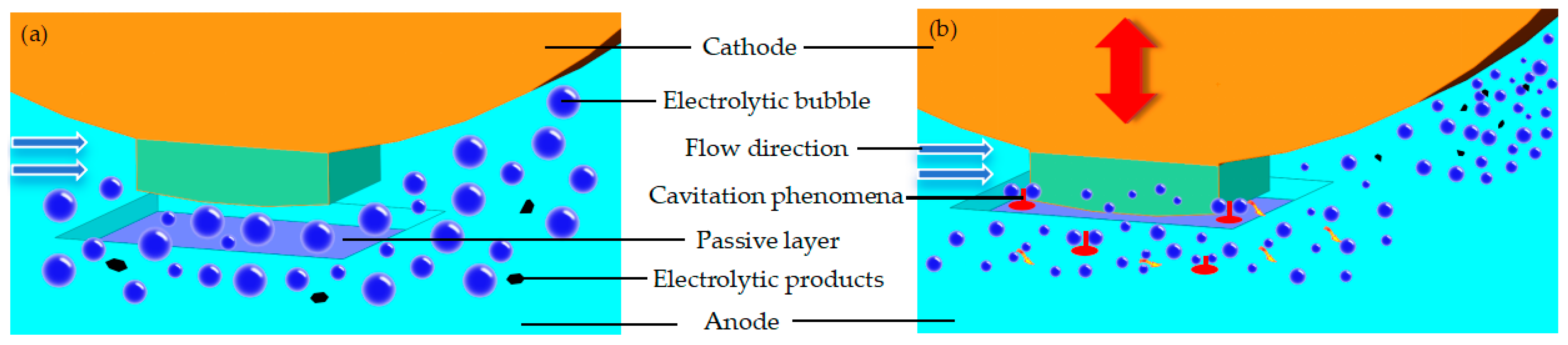
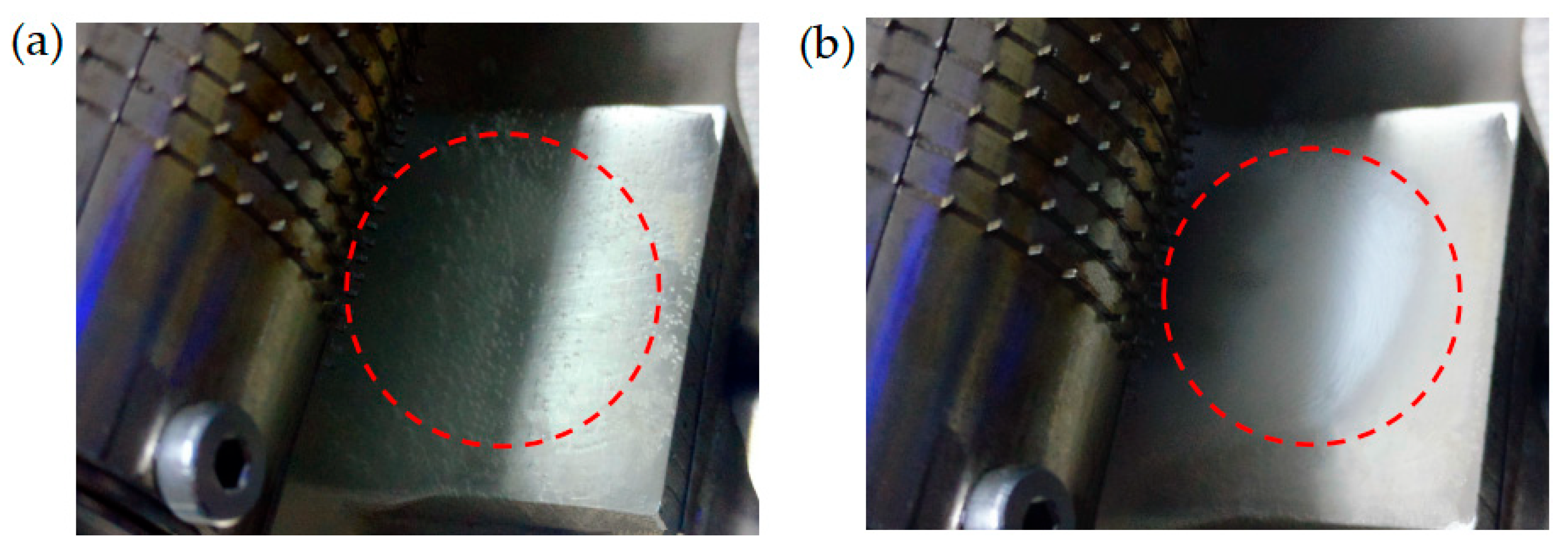
- Analysis of metal surface pitting formation dynamics revealed that ultrasonic energy fields disrupt passive film formation during micro-electrolytic machining via combined mechanical–chemical effects, while enhancing electrolyte renewal, product discharge, and material erosion rates. Future work could focus on developing real-time passive film monitoring techniques using electrochemical impedance spectroscopy, optimizing ultrasonic parameters through machine learning to control material removal rates, and exploring hybrid processes integrating ultrasonic vibration with abrasive particles for enhanced surface finishing. This research has potential applications in aerospace for turbine blade repair, automotive for precision machining of engine components, and marine engineering for corrosion-resistant surface modification of ship hulls, addressing industrial needs for high-precision, environmentally friendly metal processing technologies.
- (4)
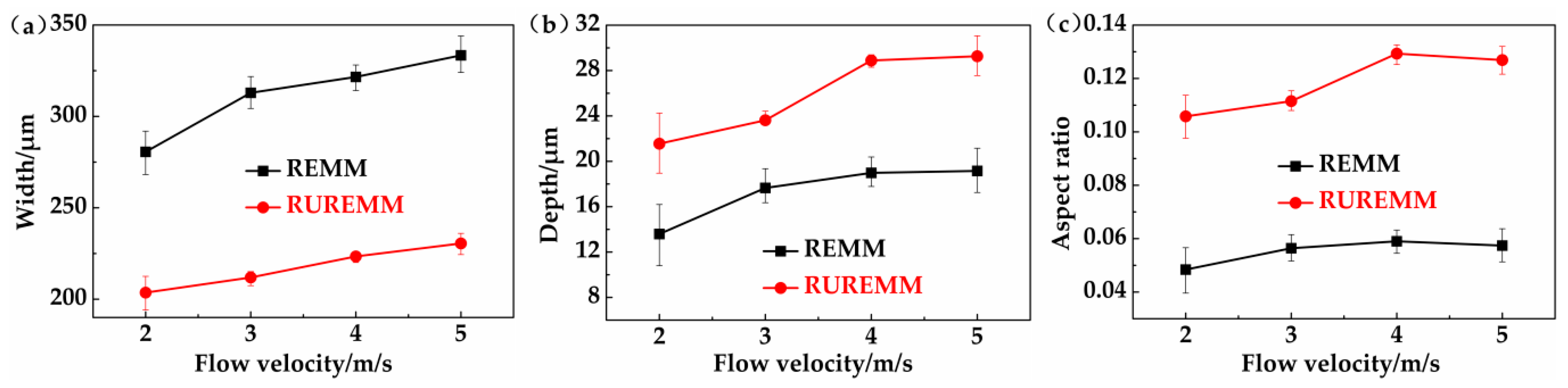
- Micro-dimple arrays were fabricated on SS304 via rotary ultrasonic-assisted reverse electrochemical machining (RUREMM), achieving 223.4 μm width and 28.90 μm depth dimples with a 0.129 aspect ratio and Ra 0.205 μm—outperforming traditional ECM. Ultrasonic micro-jets and homogenized flow fields suppressed stray corrosion and bubble unevenness, enabling this advancement. Key parameters included 35 μm amplitude, 4 m/s electrolyte flow, and optimized machining gap. Future work focuses on in situ monitoring systems, AI-driven parameter optimization for dimple consistency, and hybrid ultrasonic-nanoparticle electrolytes to enhance MRR. Applications span aerospace turbine blade texturing, automotive piston ring lubrication enhancement, and biomedical implant osseointegration, addressing high-precision microfabrication demands for defect-free metal components.
Author Contributions
Funding
Data Availability Statement
Conflicts of Interest
Nomenclature
| Item | Symbol | Unit |
| Radial Electrochemical Micromachining | REMM | |
| Radial Ultrasonic Rolling Electrochemical Micromachining | RUREMM | |
| Electrical and liquid constants of electrochemical machining | ηωσUR | |
| Vibration velocity component along the X-axis | VX | [m/s] |
| Vibration velocity component along the Y-axis | Vy | [m/s] |
| Initially set electrode gap | ΔZ | [μm] |
| One point within the energization time region [t1, t2] | ξ | [min] |
| Material removal speed of workpiece | v(t) | [mm/min] |
| Period of ultrasonic vibration | T | [min] |
| Height of outlet | H1 | [mm] |
| Height of inlet | H2 | [mm] |
| Left lateral wall spacing | D1 | [mm] |
| Right lateral wall spacing | D2 | [mm] |
| Entrance side wall spacing | D3 | [mm] |
| Machining gap | h | [μm] |
| Electrode spacing | L1 | [μm] |
| Electrode width | L2 | [μm] |
| Angle between the cross-section and the horizontal plane | α | [°] |
| Protrusion size | A × A | [μm] |
| Rotation speed | Vr | [r/min] |
| Pulse voltage | U | [V] |
| Pulse frequency | f1 | [kHz] |
| Workpiece diameter | D | [mm] |
| Electrolytic velocity | Ve | [m/s] |
| Ultrasonic amplitude | A | [μm] |
| Inter-electrode gap | Δ | [μm] |
| Electrolyte concentration | wt | [%] |
| Electrolyte temperature | Te | [°C] |
| Ultrasonic vibration frequency | f2 | [kHz] |
| Machining time | t | [min] |
References
- Monteiro, P.L.; Labiapari, W.S.; Da Silva, W.M., Jr.; Costa, H.L. Durability of deterministic textures produced by maskless electrochemical texturing (MECT) during Skin pass cold rolling. Wear 2025, 562–563, 205638. [Google Scholar] [CrossRef]
- Xu, P.; Li, Q.H.; Wang, C.Y.; Li, L.; Tan, D.P.; Wu, H.P. Interlayer healing mechanism of multipath deposition 3D printing models and interlayer strength regulation method. J. Manuf. Process. 2025, 141, 1031–1047. [Google Scholar] [CrossRef]
- George, A.; Dhanish, P.B.; Mathew, J. Wear characteristics of WS2 nanoparticle-assisted micro-EDM textured carbide inserts during machining of Ti6Al4V. Tribol. Int. 2024, 195, 109640. [Google Scholar] [CrossRef]
- Yuan, J.; Gastaldi, C.; Goy, E.D.; Chouvion, B. Friction damping for turbomachinery: A comprehensive review of modelling, design strategies, and testing capabilities. Prog. Aerosp. Sci. 2024, 147, 101018. [Google Scholar] [CrossRef]
- Li, L.; Xu, P.; Li, Q.H.; Yin, Z.C.; Zheng, R.Y.; Wu, J.F.; Bao, J.J.; Qi, H.; Tan, D.P. Multi-field coupling particle flow dynamic behaviors of the microreactor and ultrasonic control method. Powder Technol. 2025, 454, 120731. [Google Scholar] [CrossRef]
- Franca, P.H.P.; Barbosa, L.M.Q.; Fernandes, G.H.N.; Machado, A.R.; Martins, P.S.; da Silva, M.B. Internally cooled tools: An eco-friendly approach to wear reduction in AISI 304 stainless steel machining. Wear 2024, 554–555, 205490. [Google Scholar] [CrossRef]
- Ahmed, A.; Masjuki, H.H.; Varman, M.; Kalam, M.A.; Habibullah, M. An overview of geometrical parameters of surface texturing for piston/cylinder assembly and mechanical seals. Meccanica 2016, 51, 9–23. [Google Scholar] [CrossRef]
- Xiao, N.; Khonsari, M.M. Thermal performance of mechanical seals with textured side-wall. Tribol. Int. 2012, 45, 1–7. [Google Scholar] [CrossRef]
- He, T.; Xu, L.; Zhang, N.; Sun, Y.B.; Qi, Y.Z.; Wu, F.H. A superspreading bioinspired micro-texture with the function of self-priming liquid for enhancing boiling heat transfer of cutting-fluid on tool surface. J. Manuf. Process. 2025, 133, 556–565. [Google Scholar]
- Chin, C.H.; Tien-Li, C.; Yen-Cheng, C.; Chien-Ping, W. Enhancing boiling heat transfer by ultrafast laser texturing of groove structures on thin-film graphene surfaces. Therm. Sci. Eng. Prog. 2025, 61, 103510. [Google Scholar] [CrossRef]
- Chen, X.; Rong, Y.; Yang, R.; Wang, M.Z.; Tao, Y.X.; Huang, Y. Graphical compensation of area coverage and stitching accuracy for galvanometric laser texturing on spherical surface. J. Manuf. Process. 2025, 134, 14–28. [Google Scholar] [CrossRef]
- Butler-Smith, P.; Burtt, N.; See, T.L. The friction of surface textured cylinder liner segments modified by Direct Laser Writing and Direct Laser Interference Patterning processes. J. Manuf. Process. 2024, 117, 366–374. [Google Scholar] [CrossRef]
- Jeon, J.H.; Choi, J.Y.; Kim, G.Y.; Kim, G.Y.; Hong, S.J.; Callanga, J.; Lee, C.; Gries, T.; Ahn, S.H. Effect of laser texturing and thermomechanical joining parameters on bond strength of steel-flax fiber reinforced vitrimer composites. J. Manuf. Process. 2024, 124, 212–225. [Google Scholar] [CrossRef]
- Kumar, A.; Ramadas, H.; Kumar, C.S.; Nath, A.K. Laser polishing of additive manufactured stainless-steel parts by line focused beam: A response surface method for improving surface finish. J. Manuf. Process. 2025, 133, 1310–1328. [Google Scholar] [CrossRef]
- Kumar, H.; Roy, T.; Jha, S. Influence of gaseous dielectrics on the wettability of Al-6061 alloy using dry µ-electrical discharge milling. Appl. Surf. Sci. 2025, 685, 162004. [Google Scholar] [CrossRef]
- Yimiao, Z.; Mingbo, Q.; Hui, L.; Yingmin, W.; Jingtao, L.; Zhaowei, L.; Yifan, D.; Cheng, H. Processing of gallium oxide crystals using liquid-immersion wire-cut electrical discharge machining. Mater. Sci. Semicond. Process. 2025, 186, 109049. [Google Scholar] [CrossRef]
- Gao, Q.; Li, K.-L.; Qin, L.; Zhang, Y.O.; Xi, X.C.; Zhao, W.S. A discharge plasma regulation method with spike current for electrical discharge machining. J. Manuf. Process. 2024, 125, 402–411. [Google Scholar] [CrossRef]
- Morovatdel, M.; Osguei, A.T.; Üstünel, Y.C.; Üstünel, Y.C.; Oliaei, S.N. Characterization of micro-wire electrical discharge machining surface texture by empirical mode decomposition. Measurement 2025, 242, 116184–116189. [Google Scholar] [CrossRef]
- Sivashankar, N.; Thanigaivelan, R.; Selvarajan, L.; Venkataramanan, K. Investigation of electrochemical micromachining on magnesium alloy using hollow tool electrode. Ultrasonics 2025, 147, 107526. [Google Scholar] [CrossRef] [PubMed]
- Fang, M.; Hou, L.L.; Yu, L.; Chu, X.F.; Cheng, X.; Wang, J.L. Research on simulation method of multiple time scales dissolution process in tube electrode pulse electrochemical machining. J. Manuf. Process. 2024, 110, 318–330. [Google Scholar] [CrossRef]
- Bhanumathy, S.; Prasanth, B.M.; Anitha, B.; Mohanakanna, R.; Nandhakumar, E.; Hariharan, P. Prediction of material removal rate of SS304 alloy in electrochemical micromachining using machine learning. Mater. Today Proc. 2023; in press. [Google Scholar] [CrossRef]
- Zhang, S.; Zhou, J.; Fu, F.; Hu, G.; Zhao, Y.; Wang, L.; Xu, Y. Electric arc electrochemical machining of Ti6Al4V titanium alloy based on high-pressure internal flushing fluid. J. Manuf. Process. 2024, 112, 60–81. [Google Scholar] [CrossRef]
- Yang, P.J.; Hung, J.C. On high resolution bubbly flow generator for gas-mixed micro electrochemical machining. J. Manuf. Process. 2024, 121, 269–288. [Google Scholar] [CrossRef]
- Jeong, J.; Kurniawan, R.; Kwak, Y.I.; Yoon, I.C.; Ali, S.; Ko, T.J. Helical groove texturing on flutes of twist drill and hole machining enhancement. J. Manuf. Process. 2024, 129, 307–318. [Google Scholar] [CrossRef]
- Du, C.; Dai, Y.; Hu, H.; Guan, C.L.; Liu, J.F.; Lai, T.; Tian, Y.Y. Atomic-level insight into process and mechanism of ion beam machining on aluminum optical surface. Vac. Technol. Appl. Ion Phys. Int. J. Abstr. Serv. Vac. Sci. Technol. 2024, 222, 113011. [Google Scholar] [CrossRef]
- Xie, L.; Tian, Y.; Shi, F.; Guo, S.P.; Zhou, G. Adaptive processing strategy of pulse ion beam for sub-nanometer precision optical components. J. Mater. Process. Technol. 2024, 327, 119341. [Google Scholar] [CrossRef]
- Wang, X.; Peng, Y. Electrochemical micromachining on nickel and nickel-based superalloys with two-tone sinusoidal signal. Electrochem. Commun. 2024, 158, 107642. [Google Scholar] [CrossRef]
- Liu, S.; Li, C.; Jin, X.; Ma, D.F.; Yan, Q.; Liu, G.D.; Cao, X.; Wang, H. Solid dielectric electrochemical polishing of 3D-printed parts Performance and mechanisms. Int. J. Mech. Sci. 2025, 285, 109822. [Google Scholar] [CrossRef]
- Chen, D.; Liu, Z.; Li, L.; Wang, W.A.; Zhou, J.X.; Song, J.L. Manufacturing of dies and an experimental study on the cold-press surface-texture forming process. J. Manuf. Process. 2023, 99, 27–37. [Google Scholar] [CrossRef]
- Ge, Z.; Wu, H.; Hu, Q.; Zhu, H.T.; Zhu, Y.W. Uniformity enhancement of flow field through optimizing nozzle structure for jet electrochemical machining. Int. J. Electrochem. Sci. 2024, 19, 100809. [Google Scholar] [CrossRef]
- Zhai, K.; Liang, Y.; Li, T.; Ma, S.H.; Du, L.Q. Research on jet electrochemical machining with coaxial megasonic assistance. Ultrason. Sonochem. 2024, 110, 107054. [Google Scholar] [CrossRef] [PubMed]
- Liu, Y.; Qu, N.; Li, H.; Zhang, Z.Y. Boundary fluid constraints during electrochemical jet machining of large size emerging titanium alloy aerospace parts in gas–liquid flows Experimental and numerical simulation. Chin. J. Aeronaut. 2025, 38, 103024. [Google Scholar] [CrossRef]
- Zhao, Y.; Lyu, Z.; Liu, W.; Zhang, B.; Clare, A.T. Submerged electrochemical jet machining with in-situ gas assistance. CIRP Ann. 2024, 73, 117–120. [Google Scholar] [CrossRef]
- Liu, W.; Cheng, A.; Dong, H.; Zhao, Y.H. Electrochemical jet machining in deep-small holes with gas assistance: Generating complex features on internal surfaces. J. Mater. Process. Technol. 2025, 335, 118662. [Google Scholar] [CrossRef]
- Yu, M.; Du, L.; Zhai, K.; Chen, H.H.; Wang, F.L.; Li, A.Q.; Wang, Z.M. Towards understanding uniformity of megasonic-assisted through-mask electrochemical micromachining based on bubble dynamics. J. Manuf. Process. 2023, 96, 125–137. [Google Scholar] [CrossRef]
- Liu, Z.; Lian, Z.; Yang, J.; Xu, J.K.; Tian, Y.L.; Yu, H.D. High-efficient and scalable fabrication of robust superhydrophobic microarrays through maskless electrochemical machining. Colloids Surf. A Physicochem. Eng. Asp. 2024, 681, 132700. [Google Scholar] [CrossRef]
- Jakob, L.; Bartsch, J. Influences on the anisotropy in through-mask electrochemical micromachining processes. Electrochim. Acta 2025, 511, 145366. [Google Scholar] [CrossRef]
- Yang, X.; Du, L.; Li, A.; Wu, M.X.; Wu, C.H.; Li, J.M. A novel method of induction electrode through-mask electrochemical micromachining. Int. J. Mach. Tools Manuf. 2024, 203, 104221. [Google Scholar] [CrossRef]
- Guerrero-Vacas, G.; Fusco, S.; Rodríguez-Valverde, M.Á.; Alabanda, O.R. Manufacturing hydrophobic surfaces on aluminium substrates by micro-milling with end-ball nose tools. J. Manuf. Process. 2024, 124, 24–37. [Google Scholar] [CrossRef]
- Li, Z.; Zhou, W.; Liu, G.; Luo, H.P.; Zhang, Y.J. Study on micro electrochemical milling with programmable dynamic eccentric rotating electrode. Precis. Eng. 2024, 91, 300–320. [Google Scholar] [CrossRef]
- Wang, S.; Liu, J.; Bao, C.; Zhu, D. Flow field design and experiment of high-efficiency electrochemical milling with large machining area. Chin. J. Aeronaut. 2025, 38, 103211. [Google Scholar] [CrossRef]
- Shen, Z.; Li, H.; Zhang, J.; Qu, N. Improving flatness of machined surface in rotating cathode electrochemical milling. J. Manuf. Process. 2024, 116, 60–76. [Google Scholar] [CrossRef]
- Cui, G.; Wang, D.; Zhu, Z.; Zhou, S.F. Accuracy analysis and improvement methods for revolving parts in counter-rotating electrochemical machining with continuous radial feeding. CIRP J. Manuf. Sci. Technol. 2024, 54, 43–56. [Google Scholar] [CrossRef]
- Yu, T.; Wang, S.; Liu, X.; Liu, S.J.; Shi, C.; Du, N. Electrochemical corrosion behavior of 7075 aluminum alloy with different ultrasonic surface rolling microstructures. J. Mater. Res. Technol. 2024, 30, 4702–4713. [Google Scholar] [CrossRef]
- Zhou, S.; Wang, D.; Cui, G.; Zhang, J.; Zhu, D. Co-rotating electrochemical machining of convex structures on the inner surface of annular parts using a flexible cathode tool. Precis. Eng. 2024, 89, 55–69. [Google Scholar] [CrossRef]
- Yang, J.; Wang, Y.; Yang, Y.; Liu, Y.F.; Zhang, W.W. Fabrication of micro holes with confined pitting corrosion by laser and electrochemical machining: Pitting corrosion formation mechanisms and protection method. J. Mater. Process. Technol. 2025, 335, 118677. [Google Scholar] [CrossRef]
- Geng, T.; Xu, Z.; Lu, J. A sustainable, high-quality method for machining film cooling holes: Cryogenic airflow-assisted electrochemical discharge drilling. J. Clean. Prod. 2023, 426, 139017. [Google Scholar] [CrossRef]
- Wang, M.; Zhang, R.; Shang, Y.; Zheng, J.S.; Wang, X.D.; Xu, X.F. Micro-milling microstructures in air-shielding ultrasonic assisted electrochemical machining. J. Manuf. Process. 2023, 97, 171–184. [Google Scholar] [CrossRef]
- Wang, C.Y.; Li, Z.; Xu, P.; Hou, Y.Q.; Tan, D.P.; Li, L. Collision modelling approach and transient response mechanism of ring-ribbed cylindric shells for underwater vehicles. Appl. Math. Model. 2025, 141, 115923. [Google Scholar] [CrossRef]
- Pandey, H.; Pawar, K.; Dixit, P. Fabrication of through alumina vias (TAV) by ultrasonic micromachining for advanced packaging applications. Mater. Sci. Semicond. Process. 2025, 185, 108923. [Google Scholar] [CrossRef]
- Zheng, G.A.; Weng, X.X.; Wang, T.; Xu, P.; Xu, W.X.; Li, L.; Xu, X.F.; Tan, D.P. Piezoelectric ultrasonic coupling-based polishing of micro-tapered holes with abrasive flow. J. Zhejiang Univ.-Sci. A, 2025; in press. [Google Scholar]
- Ren, M.; Zhu, D.; Zhou, X.; Wang, Y.M.; Li, S.L. Surface quality enhancement in ultrasonic vibration-assisted electrochemical machining. Colloids Surf. A Physicochem. Eng. Asp. 2024, 703, 135188. [Google Scholar] [CrossRef]
- Zhang, Y.; Ni, Q.; Ouyang, Z.; Bian, H.W.; Bu, T.Q. Controllable vertical and radial corrosion by step flow fields for fabricating large aspect ratio micro-cone arrays in through-mask electrochemical micromachining. J. Mater. Process. Technol. 2025, 335, 118664. [Google Scholar] [CrossRef]
- Chen, Z.; Liu, Y.; Wang, T.; Wang, K. Ultrasonic assisted electrochemical discharge milling of complex glass microstructure with high-quality. J. Manuf. Process. 2023, 94, 94–106. [Google Scholar] [CrossRef]
- Wang, P.; Hu, J.; Hu, H.; Yu, D.G.; Yin, Z.; Zou, H.Y.; Lai, T. Debris motion and taper suppression in EDM deep hole machining assisted by longitudinal/torsional ultrasonic vibration. J. Manuf. Process. 2025, 133, 798–810. [Google Scholar] [CrossRef]
- Huang, Y.; Fang, C.; Yang, F.; Gong, S.L.; Wang, X. Experimental investigation of electrochemical machining for involute internal spline using cathode working teeth sheet with circumferential vibration. Precis. Eng. 2024, 88, 905–914. [Google Scholar] [CrossRef]
- Xu, X.; Ma, Y.; Gong, Y.; Li, H.; Wang, Z.C.; Niu, P.F.; Pang, W. Mass-loaded suspended piezoelectric micromachined ultrasonic transducer array towards flexible stretchable electronics evaluation. Sens. Actuators A. Phys. 2025, 381, 116048. [Google Scholar] [CrossRef]
- Tan, Y.F.; Ni, Y.S.; Xu, W.X.; Xie, X.S.; Li, L.; Tan, D.P. Key technologies and development trends of the soft abrasive flow finishing method. J. Zhejiang Univ.-Sci. A Appl. Phys. Eng. 2023, 24, 1043–1064. [Google Scholar] [CrossRef]


| Item | Parameter | Unit |
|---|---|---|
| Height of outlet [H1] | 1.20 | [mm] |
| Height of inlet [H2] | 0.60 | [mm] |
| Left lateral wall spacing [D1] | 1.80 | [mm] |
| Right lateral wall spacing [D2] | 2.20 | [mm] |
| Entrance side wall spacing [D3] | 0.50 | [mm] |
| Machining gap [h] | 100 | [μm] |
| Electrode spacing [L1] | 800 | [μm] |
| Electrode width [L2] | 400 | [μm] |
| Item | Symbol | Value | Unit |
|---|---|---|---|
| Protrusion size | A × A | 400 × 400 | [μm] |
| Rotation speed | Vr | 0.008 | [r/min] |
| Pulse voltage | U | 10 | [V] |
| Pulse frequency | f1 | 16 | [kHz] |
| Workpiece diameter | D | 50 | [mm] |
| Electrolytic velocity | Ve | 2, 3, 4, 5 | [m/s] |
| Ultrasonic amplitude | A | 5, 20, 35, 50 | [μm] |
| Inter-electrode gap | Δ | 20, 60, 100, 140 | [μm] |
| Electrolyte concentration | wt | 10 | [%] |
| Electrolyte temperature | Te | 25 | [°C] |
| Ultrasonic vibration frequency | f2 | 28 | [kHz] |
| Machining time | t | 5 | [min] |
| Items | Machining Gap [μm] | Short Circuits | Width [μm] | Depth [μm] | Aspect Ratio |
|---|---|---|---|---|---|
| REMM | 20 | 2 | 384.5 | 16.15 | 0.0420 |
| 60 | 0 | 351.6 | 18.96 | 0.0539 | |
| 100 | 0 | 312.9 | 17.65 | 0.0564 | |
| 140 | 0 | 221.2 | 9.91 | 0.0448 | |
| RUREMM | 20 | 4 | 281.1 | 14.51 | 0.0516 |
| 60 | 0 | 260.5 | 22.48 | 0.0863 | |
| 100 | 0 | 227.2 | 20.62 | 0.0908 | |
| 140 | 0 | 211.3 | 15.63 | 0.0740 |
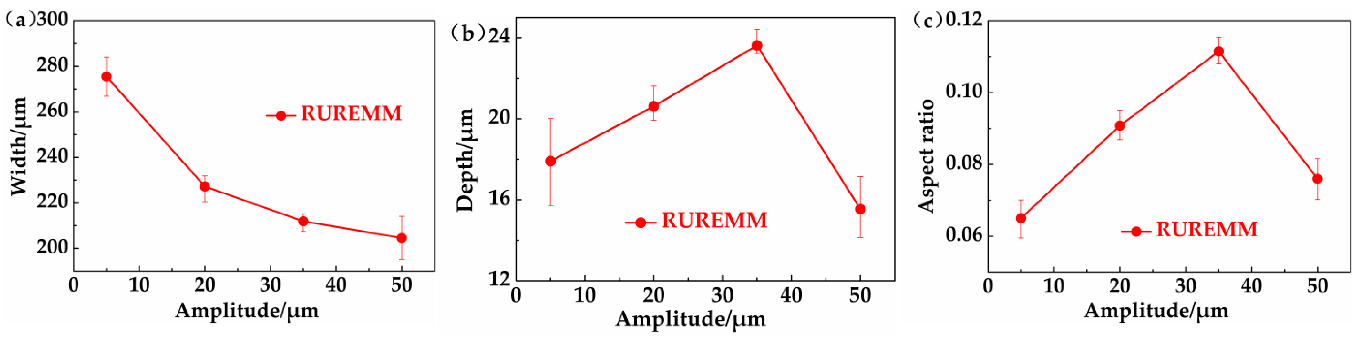
| Items | Amplitude [μm] | Short Circuits | Width [μm] | Depth [μm] | Aspect Ratio |
|---|---|---|---|---|---|
| RUREMM | 5 | 0 | 275.5 | 17.91 | 0.0650 |
| 20 | 0 | 227.2 | 20.62 | 0.0908 | |
| 35 | 0 | 211.9 | 23.62 | 0.1115 | |
| 50 | 3 | 204.6 | 15.54 | 0.0760 |
| Items | Flow Velocity [m/s] | Short Circuits | Width [μm] | Depth [μm] | Aspect Ratio |
|---|---|---|---|---|---|
| REMM | 2 | 2 | 280.6 | 13.59 | 0.0484 |
| 3 | 0 | 312.9 | 17.65 | 0.0564 | |
| 4 | 0 | 321.6 | 18.98 | 0.0590 | |
| 5 | 0 | 333.4 | 19.15 | 0.0574 | |
| RUREMM | 2 | 1 | 203.6 | 21.55 | 0.1058 |
| 3 | 0 | 211.9 | 23.62 | 0.1115 | |
| 4 | 0 | 223.4 | 28.89 | 0.1293 | |
| 5 | 0 | 230.5 | 29.26 | 0.1269 |
Disclaimer/Publisher’s Note: The statements, opinions and data contained in all publications are solely those of the individual author(s) and contributor(s) and not of MDPI and/or the editor(s). MDPI and/or the editor(s) disclaim responsibility for any injury to people or property resulting from any ideas, methods, instructions or products referred to in the content. |
© 2025 by the authors. Licensee MDPI, Basel, Switzerland. This article is an open access article distributed under the terms and conditions of the Creative Commons Attribution (CC BY) license (https://creativecommons.org/licenses/by/4.0/).
Share and Cite
Tong, W.; Li, L. Analysis of Flow Field and Machining Parameters in RUREMM for High-Precision Micro-Texture Fabrication on SS304 Surfaces. Processes 2025, 13, 2326. https://doi.org/10.3390/pr13082326
Tong W, Li L. Analysis of Flow Field and Machining Parameters in RUREMM for High-Precision Micro-Texture Fabrication on SS304 Surfaces. Processes. 2025; 13(8):2326. https://doi.org/10.3390/pr13082326
Chicago/Turabian StyleTong, Wenjun, and Lin Li. 2025. "Analysis of Flow Field and Machining Parameters in RUREMM for High-Precision Micro-Texture Fabrication on SS304 Surfaces" Processes 13, no. 8: 2326. https://doi.org/10.3390/pr13082326
APA StyleTong, W., & Li, L. (2025). Analysis of Flow Field and Machining Parameters in RUREMM for High-Precision Micro-Texture Fabrication on SS304 Surfaces. Processes, 13(8), 2326. https://doi.org/10.3390/pr13082326