Abstract
Based on admirable porous media performance and the popularity of additive manufacturing technology, gradient porous media are progressively being applied in increasing fields. In this study, convection heat transfer within a square vented cavity, partially occupied by two copper metal foam layers of and PPI saturated with nanofluid, was assessed numerically. The left wall was heated uniformly and non-uniformly by applying multi-frequency spatial heating following a sinusoidal function. Governing equations, including continuity, the Darcy–Brinkmann–Forchheimer model, and local thermal non-equilibrium energy equations, were adopted and solved by employing the finite volume method. The influences of relevant parameters, including nanoparticle concentrations , Reynolds number (), inlet and outlet port aspect ratios , three outlet vent opening locations ( left, () middle, and () right), sinusoidal offset temperature (, ), frequency (), and amplitude (), were examined. The results demonstrate that flow and heat transfer fields are impacted mainly by these parameters. Streamlines are more intensified at the upper-left corner when the outlet opening vent is shifted towards the right-corner upper wall. Fluid- and solid-phase Nusselt number increases , , , , and are raised, specifically when . The Nusselt number remains constant when the frequency is raised from to , definitely when . In uniform and non-uniform heating cases, the Nusselt number of both phases remains constant as the outlet port is shifted right for and slightly for higher as the outlet vent location is translated from left to right.
1. Introduction
The augmentation of the convection heat transfer inside vented cavities has become one of the main goals pursued by many researchers in the last few years. This type of enclosure is common in engineering applications, such as the cooling of electronic and microelectronic equipment, heating and air conditioning, chemical catalytic reactors, drying processes, solar energy collection, nuclear reactors, underwater vehicles, 3D-printing technology, gear transmission systems, static mixed space structures, and heat exchangers [1,2,3,4,5]. Additionally, some have required porous media to enhance convection heat transfer [6,7,8]. In numerous heating and cooling thermal applications, the crucial problem is the low thermal conductivity of traditional fluids occupied in these cavities such as air, water, and oil. Therefore, scientific research has found that the main two important techniques for enhancing the low thermal conductivity of conventional fluids are using nanoparticles dispersed in fluids and/or totally or partially filling the regions with porous materials according to the type of application [9,10,11,12,13].
The technique of filling enclosures with saturated porous media to enhance the heat transfer rate has been considered by many researchers and also adopted in vented enclosures to attain higher effective thermal properties, which results in better thermal performance. The problem of non-Darcy flow and heat transfer through a vertical confined porous matrix with two wall infiltrations was analyzed in [14] using the control volume-based finite difference scheme. They studied the influence of the opening location and infiltration velocity variation and found that the Nusselt number grows with an infiltration velocity. Later, ref. [15] numerically steady mixed convection flow in a square vented cavity fully filled with a fluid-saturated porous medium. They scrutinized the innovation effect of the Rayleigh number, Peclet number, and inlet width as the fraction cavity height for both aiding and opposing flow. This fraction alteration affected the transfer rate inside the enclosure for certain values of Rayleigh and Peclet numbers. Afterward, ref. [16] numerically mixed convection heat transfer inside a square vented cavity occupied with porous media by using the finite difference method. They observed the outcome of changing the values of the enclosure outlet port width and position, Rayleigh number, and Peclet number for aiding and opposing mixed convection cases. The main conclusion of their work is that the maximum heat transfer take place when the outlet port is located at the upper-right corner, and the minimum transfer of heat is achieved for the case exit vent positioned at the upper-left and lower-right corners. Then, various cases of mixed convection in a fluid-saturated porous enclosure under suction and/or injection influences were handled by refs. [17,18,19]. They numerically considered the case of Darcy and non-Darcy mixed convection under multiple suction and non-Darcy mixed convection under suction/injection effects with non-isothermal sinusoidally varying temperature at the vertical sidewall. The variation in relevant parameters was accomplished in the Grashof number, Rayleigh number, suction/injection velocity, vent width, and amplitude of sinusoidally varying temperature profile. They deduced that the Nusselt number affected the flow and temperature fields of the aforementioned governing parameters. Furthermore, drying is one of the important applications for vented porous enclosures and heat and mass transfer processes inside this type of medium, which was investigated numerically using the finite volume method in ref. [20]. They examined the variation effects of Rayleigh and Darcy numbers, opening port location, and cavity inclination angles on the convective heat and moisture transfer rate and volume flow rate across this enclosure. Their results demonstrate that increasing the Rayleigh number tends to enhance the transport performance, and a reduction in the Darcy number causes diffusion domination, whereas the heat and moisture transfer is reduced when vents are located far from the source of heating and moisture.
Moreover, in ref. [21], the authors examined the influence of adding water-saturated porous media into a vented square enclosure—its bottom wall being heated by constant heat flux—on the mixed convection heat transfer rate. The Richardson number, Darcy number, and diameter of porous particles affected the relevant parameters studied, and they found that the Darcy number results in the Nusselt number increasing, while increasing particle diameter produces a reduction in Nusselt number values. Steady natural and mixed convection through water-saturated aluminum metal foam occupied within a square vented cavity was examined numerically in ref. [22]. The studied variable parameters involved were the Grashof number, Reynolds number, porisity of metal foam, and inlet width as a fraction of the enclosure height. And the main deductions from the study were, first, that the temperature distribution of the fluid has little difference from that of the solid matrix and, second, the average Nusselt number rises with the inlet width to enclosure height fraction, with the Reynolds number increasing and porosity decreasing. On the other hand, ref. [23] observed the finite element numerical solution of thermal and entropy generation performance in a porous square enclosure with open vents. Two cases for thermal boundary conditions were taken into consideration by the authors, and they contemplated the outcome of the Peclet number, Rayleigh number, aspect ratio, and width of inlet as a fraction of enclosure width variations. They deduced that average Nusselt and entropy generation numbers increase, whereas the average Bejan number decreases with an increasing ratio of inlet width as a fraction of enclosure width. Additionally, triple-diffusive mixed convection heat and mass transfer in a vented cavity filled with porous media was inspected numerically in ref. [24]. They inspected the variation influence of the Darcy–Rayleigh number, Peclet number, and two Lewis numbers and deduced that the rate of heat and mass transfer inside a cavity increases as the Peclet number and Darcy–Rayleigh number are raised. Also, ref. [25] numerically scrutinized the mixed convective heat transfer in a vented porous enclosure subjected to external magnetic fields for five different heating arrangements. The Reynolds, Richardson, Darcy, and Hartmann numbers; angle of the magnetic field; porosity; and different heating configurations were the pertinent parameters involved in their study in order to examine their effects on the flow field and heat transfer characteristics. Mainly, it was deduced that the location of heating at corners has a noteworthy outcome on the heat transfer process, and heating rises with an increasing Reynolds number, porosity, and Darcy number. Further, experimentally mixed convection in a vented enclosure with the side differentially heated and occupied with a water-saturated coarse-grained porous medium was established in ref. [26]. They examined the influence of relevant parameter variations on the thermal performance inside the cavity, including the Rayleigh and Reynolds numbers, and they deduced that the Nusselt number is significantly higher for an enclosure filled with a porous medium, as compared to pure-fluid occupying when Rayleigh and Reynolds numbers are increased. Meanwhile, ref. [27] conducted numerical analysis of transient mixed convection heat transfer and thermal characteristics in a vertically vented porous square cavity filled with air-saturated fibrous material. The relevant parameters premeditated by them included the Richardson, Reynolds, and Darcy numbers, in addition to solid/fluid thermal conductivity ratio, porosity, and inlet/outlet port width. Primarily, they deduced that the presence of porous material enhances thermal performance, and, also, the mean Nusselt number increases significantly with the mentioned studied parameters increasing, except that increasing porosity causes a reduction in the mean Nusselt number value.
Vented enclosures with inlet and outlet ports crossed by porous material saturated with nanofluid have been considered by many researchers. The authors of [28] inspected numerically steady double-diffusive mixed convective heat transfer in a vented square enclosure filled with porous media saturated with nanofluid. In their study, they focused on the influence of variation parameters including the Reynolds, Prandtl, Rayleigh, Lewis, and nanofluid Lewis numbers, and other relevant parameters on heat and fluid flow features. They deduced that the average Nusselt number increases with Rayleigh and Reynolds numbers increasing and Lewis number reduction. Afterward, transient mixed convection heat transfer in an inclined wavy vented enclosure occupied with hybrid nanofluid-saturated porous media for both adding and opposing flow was performed using the finite difference numerical method in ref. [29]. He carried out his investigation for wide ranges of Peclet and Rayleigh numbers, wavy wall amplitude, and cavity inclination angles and deduced that mixed convection as well as the Nusselt number are amplified as the wavy wall amplitude and nanoparticle volume fraction grow. Also, it has been gathered that the Nusselt number is more effectual than opposing the flow case in aiding the flow case. Furthermore, ref. [30] proposed the convection heat transfer mode in a square cavity with inlet and outlet opening ports filled with copper-oxide water nanofluid-saturated porous material by utilizing finite element analysis. The relevant physical parameters in their study included the nanoparticle concentration, Reynolds Number, Grashof number, Darcy number, and Prandtl number, and they focused their efforts to explore the outcomes of these parameters on the flow field and thermal distribution. They noticed that the thermal distribution inside the enclosure, including Nusselt number, augments with an increasing nanoparticle concentration, heated source length, and Grashof number. Moreover, the problem of mixed convection inside an enclosure with inlet and outlet vents under the impression of a periodic magnetic field and filled with porous media saturated with oxytactic bacteria nanofluid was observed numerically in ref. [31]. The variation outcomes of relevant parameters, the Peclet, Richardson, and Lewis numbers, were contemplated, and they attained that a large percentage of heat transfer augmentation takes place between the lowest and highest values of Peclet numbers.
Very rare inquisitions were found for partially filled porous media vented cavities, either porous blocks or porous layers with different geometries, regardless of the fluid used to saturate the porous material. The problem of a partially filled porous enclosure with an inlet and outlet port opening was handled numerically in ref. [32]. Two geometrical porous media layer arrangements, single-channel and double-channel formations, were analyzed, and their results revealed that the gap between a porous substrate and solid wall reduces the averaged flow through porous material to zero. Additionally, refs. [33,34] numerically scrutinized flow thermal analysis over porous blocks inside a square vented cavity. The variations influenced the block aspect ratio, block porosity, and heat flux on the flow field and heat transfer rate. As a result of their work, the block aspect ratio, porosity of blocks, and heat flux, increasing the influence of the flow structure in the cavity and Nusselt number, were improved with the rise in porosity and heat flux. Moreover, two porous layers of different permeability occupied partially in an enclosure with inlet and outlet opening ports were taken into consideration in ref. [35], accomplished numerically by utilizing the finite volume method for various values of Reynolds, Richardson, and Darcy numbers, permeability ratio, cavity aspect ratio, and direction of flow (aiding and opposing). They concluded that rising aspect and permeability ratios augment both the Nusselt number and friction coefficient. Furthermore, ref. [36] contemplated numerically mixed convection heat transfer for the existence of a triangular porous material layer inside a vented square enclosure. The outcome of changing the Richardson and Darcy numbers, heater length, and different locations of porous layer was assessed in their work, and they deduced that all these parameters essentially influence the flow and heat transfer field. In addition, a truncated conical heat generating porous bed was incorporated partially in a ventilated enclosure and established numerically by refs. [37,38] for two situations of cold fluid injection location and bottom and side injection. They meditated the steady-state mixed convection heat transfer for a wide range of implemented parameters, Richardson, Reynolds, Grashof, Prandtl, and Darcy numbers. The flow mechanism inside the cavity and average Nusselt number depends mainly on the Richardson number, which was the major deduction drawn from their inspection. Also, refs. [39,40] proposed the thermal performance of a ventilated cavity with a porous partition located in the enclosure center and they investigated the partition height and thickness effect. Additionally, the influence of various ranges of Darcy, Rayleigh, and Reynolds numbers was analyzed, and they chiefly concluded that the rate of heat transfer increases as Reynolds number values are raised, and partition has very little influence on heat transfer, but its dimensions and permeability impact the temperature field. Then, a partially curved porous layer saturated with hybrid nanofluid inserted inside a vented cavity under the action of inclined magnetic field was observed in ref. [41] in order to examine the thermal performance and entropy generation characteristics. They scrutinized a wide range of relevant parameters, including Reynolds number, magnetic field strength, permeability, height, position, and curvature size of the porous layer. They gathered that the Nusselt number increases with rising Reynolds and Hartman numbers, and the Nusselt number is affected by porous layer geometry. On the other hand, ref. [42] performed convection heat transfer in a flexible-walled vented enclosure occupied by hybrid nanofluid and a “perforated and non-perforated” porous plate. Their numerical examination was carried out for different values of Reynolds, Hartmann, Cauchy, and Darcy numbers and showed that a cavity without a porous plate provides the highest thermal performance in the absence of a magnetic field, while using a porous plate results in a higher Nusselt number when a magnetic field is used. Further, mixed convection in a vented cavity partially furnished with different nanofluid-saturated porous layers and its bottom wall are heated by a discrete heat source, as inspected numerically in ref. [43]. They inquired about the consequence of the Reynolds, Darcy, and Grashof numbers, nanoparticle type and volume fraction, and porous layer thickness and position. Mainly, it was deduced that the Nusselt number increases with the nanoparticle volume fraction and Reynolds and Grashof numbers increasing, whereas porous layer size augmentation tends to intensify the heat transfer rate.
According to the relevant above-mentioned literature survey and knowledge of the author, the present study is devoted to numerically investigating convection heat transfer in a square vented cavity partially filled with two layers of metal foam and saturated with nanofluid, which has not been considered yet. The outlet opening port on the top cavity wall is located at three different positions. Layers of copper foam have the same porosity but different pores per inch for PPI values. As the sinusoidal heating condition is chiefly applicable in thermal and engineering systems, the enclosure’s left vertical sidewall is subjected to a half-sinusoidal heating condition in addition to the constant temperature case, which can be mentioned as the offset temperature. The main relevant parameters considered in the present study are the Reynolds number, inlet and outlet port dimensions, outlet vent opening location, volume fraction of copper nanofluid particles, and different offset, amplitude, and frequencies for the multi-frequency half-sinusoidal heating temperature profile. Additionally, the results obtained are validated with good agreement. Consequently, the outcomes are beneficial for thermal design associated with electronic cooling, waste heat recovery systems, convective drying, solar collectors, etc., and enhancing the thermal performance in such applications. For instance, in solar heating using flat plate solar, compound parabolic, or evacuated tube collectors, multi-frequency sinusoidal heating may appear because of different situations, like uneven irradiance, long plate, multiple inlets, curved reflectors, shadowing, or solar load variation with position. In these application areas, two layers of metal foam with different PPI values can be utilized to enhance heat transmission between the hot cavity wall and working fluid that is used for a residential heating system. A heat transfer enhancement takes place as a result of the increasing heat transfer surface area that comes from using metal foam in addition to the improved thermal properties of working nanofluid. As far as the authors know, the presence of more than one layer of metal foam with non-uniform sinusoidal heating has not been performed formerly in the literature. Moreover, the same strategy can be performed with other applications, such as convective drying, electronic cooling, and other thermal management systems.
2. Computational Method
2.1. Problem Statement and Boundary Conditions
The present study focuses on convection heat transfer in a steady two-dimensional square open cavity of equal height and length , as depicted in Figure 1a. The left vertical sidewall of the cavity is heated in a constant and non-uniform hot temperature condition , whereas the remaining walls are insulated perfectly. Non-uniform heating is applied with multi-frequency spatial heating conditions following a sinusoidal function and offset temperature (), as illustrated in Figure 1b. This vented enclosure is occupied partially with two equal-width () copper metal foam layers of the same porosities but different types of pores per inch of PPI. The remaining part of the cavity comprises copper–water nanofluid in different volumes of solid nanoparticle fractions and is also used to saturate the two layers of porous media. The inflow cold fluid () opening is located on the left-lower corner, and the cavity outflow opening is fixed at the top-left corner. The inlet port size is the same as that of the outlet port. However, the outlet opening location is extended from the left sidewall by a variable distance , which indicates three different locations for it (left, middle, and right openings). The temperature discrepancy between the left vertical hot wall and through-stream close to it, which has a constant velocity at the enclosure inlet, induces buoyancy effects, while the inlet and outlet ports of width are responsible for ascending forced convection.
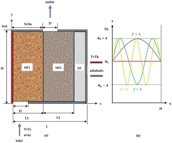
Figure 1.
Physical domain for partially filled vented cavity: (a) domain of vented cavity; (b) non-uniform sinusoidal temperature variation on left sidewall.
2.2. Computational Configurations and Assumptions
For the two layers of metal foam occupied in the vented cavity in the present work, convenient and significant assumptions are taken into consideration. These assumptions are steady-state, two-dimensional, laminar flow, incompressible, and the radiative heat transfer, thermal dispersion, and viscous energy dissipation effects that are supposed to be irrelevant. The irrelevance of radiation heat transfer is due to the temperature value of metal foam’s solid and fluid phases, which are not high enough to feature radiation, and, also, as the metal foam structure is highly conductive, convection and conduction heat transfer modes dominate over radiation heat transfer. However, using water-based nanofluid has a very low radiation effect according to water’s opaque properties, even if its temperature value is high. In addition, viscous energy dissipation that results in high fluid velocity and low porosity or high-density porous media situations plays a major role in the fluid-phase energy equation [44]. However, the heat transfer problem becomes more complicated, and the fluid velocity is not high enough; therefore, the viscous dissipation outcome is neglected in the present study. In addition, it is supposed that the porous media are homogeneous, thermally and hydrodynamically isotropic, and saturated with a single-phase nanofluid that is in local thermal non-equilibrium with a solid matrix of metal foam. As the metal foam utilized in the present study is isotropic, produced with controlled porosity and cell size, ignoring boundary effects near boundaries, and macroscopic volume averaged models for governing equations are used, homogenous assumption can be applicable. Also, because of the metal foam solid phase’s high thermal conductivity and high porosity, which reduces the contact fluid volume with the solid matrix and allows for interfacial convection heat transfer between solid and fluid phases to take place, the local thermal non-equilibrium assumption can be stated. Furthermore, owing to the absence of an air gap, surface roughness, and non-conformal contact in addition to simplifying the numerical solution, thermal contact resistance between the two layers of copper metal foam is assumed to be disregarded. The thermophysical properties of fluid and porous media are constant, except for the density dependency of the buoyancy term in the momentum equation, which is satisfied by Boussinesq approximation. Also, the domain boundaries are impermeable, while the interface between nanofluid and metal foam is permeable. Additionally, it is idealized that water as a base fluid and solid copper nanoparticles are in thermal equilibrium, and there is no slip velocity between them. The Forcheimer–Brinkman-extended Darcy model is employed for porous media.
According to all the aforementioned hypotheses, the governing equations for mass, momentum and energy for porous regions, followed by that for the nanofluid region, can be presented as follows [10,43,45]:
For the two metal foam layers:
Continuity Equation
Momentum Equations
where is pressure, is porosity, is permeability, and is Forchheimer coefficient, which can be determined from [43].
Energy Equations
In the present study, the characteristics of metal foam, such as permeability, interfacial area density (), interfacial heat transfer coefficient (), and other parameters, can be found in refs. [46,47,48,49]. Additionally, subscript refers to the metal foam layer. When , it denotes the first layers, which extend through the distance , and when , it signifies the second layer that spreads the distance . Also, is the fluid-phase temperature, is the solid-phase temperature, and and are the solid- and fluid-phase thermal conductivity.
For the nanofluid layer: ()
Continuity Equation
Momentum Equations
Energy Equation
The following dimensionless numbers and parameters are incorporated to reformulate the governing equations into a dimensionless construction in order to generalize the study and reduce the examination parameters: , , , , , , , , , , , , , .
Therefore, Equations (1)–(9) can be represented as follows:
For the two metal foam layers:
Continuity Equation
Momentum Equations
Energy Equations
For the nanofluid layer:
Continuity Equation
Momentum Equations
Energy Equation
The thermal characteristics that prescribe the working nanofluid effective physical properties as a function of the nanoparticle concentration are the density , dynamic viscosity , thermal expansion coefficient , heat capacitance and thermal conductivity [48,50]. The following equations can be utilized to obtain these thermophysical properties:
The thermophysical properties of the water base fluid and copper nanoparticles are listed in Table 1 and considered to be invariable, apart from density, which changes according to be the Boussinesq approximation.

Table 1.
Thermophysical properties of base fluid and copper nanoparticles [48,50].
The pressure term introduced in dimensionless momentum equations of metal foam and nanofluid layers is eliminated by utilizing the definition of velocity components and vorticity in terms of stream function as , , and . Then, the usual manipulation of the vorticity-stream function approach is implemented and, thus, the governing equations employed in the present study are cast for metal foam and nanofluid and become the following:
For the two metal foam layers:
Continuity Equation
Momentum Equation
Energy Equations
For the nanofluid layer:
Continuity Equation
Momentum Equation
Energy Equation
Boundary conditions of the present problem in dimensionless form can be stated as [15,45,50,51,52]:
Left hot wall: , , , , (uniform heating) or (non-uniform sinusoidal heating) on , .
Inlet port: , , , , on , .
Bottom adiabatic wall: , , , , on , .
Right adiabatic wall: , , , , on , .
Top adiabatic wall: , , , , on , when or and when .
Outlet port: , on , when or when .
Porous media layers interface: , , , , , , , , , , on , .
As the local thermal non-equilibrium model was taken into consideration, two temperature gradients were obtained inside the cavity, namely the temperature distribution for the fluid phase and solid matrix. Therefore, to assess the rate of heat transfer from the left vertical sidewall to the metal foam region, there must be two separated Nusselt number values evaluated for each phase. Thus, the local value of the Nusselt number in the nanofluid and solid phases can be formulated as:
The mean values of the Nusselt number of the nanofluid and solid phases, which are found by integrating the local mean value along the left vertical wall, can be expressed as:
In the present study, the copper metal foam of and pores per inch is chosen as the first () and second () porous media layers, respectively. The thermophysical properties of copper are given in Table 1.
2.3. Limitations of Mathematical Modelling and Admissible Model Applications
In the present study, some assumptions were stated in the previous subsection in order to simplify the heat transfer problem and its mathematical model. These assumptions produce a number of limitations when the current mathematical modelling is employed to investigate the fluid and heat flow field inside similar vented enclosures that are used in technical applications. As stated previously, the mathematical model’s stated assumptions include steady-state laminar, single-phase, and incompressible flow; ignoring thermal dispersion, radiation heat transfer, and viscous dissipation effects; and the metal foam material is homogenous, thermally and hydrodynamically isotropic, local thermal non-equilibrium, and saturated with single-phase nanofluid. Also, fluid and porous media thermophysical properties are constant, except for density temperature dependency. Therefore, according to these assumptions, the current model can be applied for systems of laminar, steady, and incompressible flow and single-phase porous media arrangements with moderate temperature values to ignore radiative heat transmission in addition to negligible thermophysical temperature alteration. Further, practical systems analyzed via the present mathematical model have to be of low to moderate fluid velocity values or low viscosity in order to neglect the viscous energy dissipation effects. Additionally, confined metal foam must be homogenous, isotropic, have uniform pore structure, no phase change, and constant porosity and effective thermal properties. Accordingly, the present mathematical modelling is not appropriate for thermal systems of turbulent fluid flow, high Reynolds number, occupied with non-uniform or graded metal foam, and strong temperature dependence of thermophysical properties. Furthermore, practical systems of high-temperature applications where radiation or nonlinear property variation becomes noteworthy are excluded from the current heat transfer model. Consequently, numerous technical and thermal applications can be simulated by employing this model, like solar air heaters, compact heat exchangers, metal foam-enhanced energy storage components, etc.
3. Grid Independence and Code Validation
The governing equations for dimensionless vorticity, stream function, and solid and fluid energy (Equations (24)–(30)) along with the conforming boundary condition (Equation (31)) for both metal foam and nanofluid were solved numerically utilizing the method of finite volume to determine the isotherm line, stream function, and Nusselt numbers inside the enclosure. The spatial derivatives of the governing equations are approximated by the central difference scheme, while the boundary and interfacial condition derivatives are approached by forward and backward difference arrangement, ref. [53]. The difference equations for boundary conditions between the interface of two metal foam layers, interface between metal foam and nanofluid, and inlet/outlet temperature and velocity (stream function) are expressed, respectively, as:
The finite volume scheme reduces the continuum problem to a discrete problem prescribed by a system of algebraic equations written as a tri-diagonal matrix, and this matrix was solved by a line-by-line procedure of a tri-diagonal matrix algorithm (TDMA) [53]. For convergence criteria, the sum of the dependent variable (, , , ) residuals was less than between successive iterations. That is, , where is any iteration level and the variable denotes the vorticity, stream function, and solid-phase and fluid-phase temperatures. Finally, algorithms based on Simpson’s rule were employed to perform the numerical integration of the average Nusselt number. In addition, an in-house numerical computer code was developed for the mentioned discretized equations and used in order to find the streamline field and temperature distribution and then calculating the Nusselt number along the heated wall.
In order to estimate the numerical result dependency on the spatial discretization of the domain and also to control the computational time with reasonable accuracy, an inclusive grid independency test was conducted. Different-sized meshes were used to determine the average Nusselt number on the hot wall for the fluid phase and solid matrix of metal foam, as exposed in Table 2. The grid refinement test was checked for two sets of certain parameter values: firstly, , , , and , and, secondly, , , , and . The results showed that nanofluid and solid matrix average Nusselt numbers have slight alteration for a grid of nodes compared with a grid of nodes and above. Consequently, the node number of was confidently adopted for entire simulations in the current work because this number of elements met the requirements of this study on grid independence, good accuracy, and computational time bounds.
Table 2.
Grid independent test, fluid and solid average Nusselt number near the left wall heated by uniform temperature using numerous mesh sizes.
The accuracy of the present developed home-constructed computer code has been extensively validated by comparing with the results of [15] in the case of mixed convection in a square porous ventilating cavity. This validation, which is illustrated in Figure 2, confronted our numerical results with their streamline and isotherms, first for the case of , and .
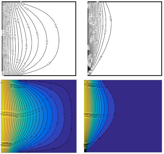
Figure 2.
Streamlines (left) and isotherms (right), [15], and current study (lower row), at , , and .
Furthermore, a second validation was accomplished for , , and two different values of and . Isotherms obtained from the present study and introduced in their study are presented in Figure 3. From both confirmations, it is evident that the present computer code can imitate the published numerical results with a high degree of accuracy. Also, it is possible to see the excellent qualitative and quantitative agreement between the results, which provides evidence for the ability of the present code to analyze the proposed study.
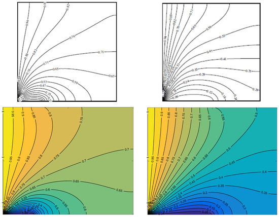
Figure 3.
Isotherms at , , and (left) , (right) [15], and current study (lower row).
4. Results and Discussion
To explore the implications of operative parameters on the thermal performance in square vented cavities occupied partially with two layers of saturated copper metal foam, temperature and streamline fields were investigated numerically for . These two layers are of different PPI values, and , the same porosities (), and equal width-to-length ratios and . It is important to mention that selecting two metal foam layers of equal porosity leads to equal effective thermal conductivity for these two layers, while the PPI value is different in order to consider two different geometries of fluid flow passages. This difference in flow passages tends towards dissimilar convection heat transfer inside each layer, rendering the number of pores and, thus, different heat transmission areas. Subsequently, the metal foam layer of exhibits conduction heat transfer, dominant through it compared with the layer of , for which convection heat transfer domination takes place. The metal foam layers and the remaining space of the enclosure are saturated with copper nanofluid with varying solid nanoparticle volume fractions between (pure water) and . Additionally, another wide range of relevant parameters is discussed in the following sections. These parameters include the Reynolds number (), aspect ratios of inlet and outlet vent dimension to height (), and outlet vent opening location ( left, middle, and right). Furthermore, the effect of the sinusoidal offset temperature ( and ), frequencies for multi-frequency half-sinusoidal heating temperature profile (and ), and amplitude of sinusoidal heating () were scrutinized for non-uniform heating on the left vertical cavity sidewall. This range of parameters was selected to simulate fluid flow and the heat transfer problem inside the current vented cavities according to the stated assumptions mentioned previously, including type of flow, working temperature range, and metal foam specifications. Also, this range can correspond to several practical and thermal applications, including electronic cooling, convective drying, and solar heating systems. Furthermore, it should be mentioned that the above values and ranges of geometrical dimensions and parameters are chosen for certain practical simulations. The vented cavity was taken as a square enclosure with equal height and length dimensions, and the width of metal foam layer dimensions is equal; however, the present simulation can be considered for other geometrical dimensions, and the obtained results will have the same physical behavior so identical qualitative conclusions are obtained.
4.1. Effect of Inlet and Outlet Port Dimensions, Reynolds Number, and Nanoparticle Volume Fraction
To illuminate the effect of inlet and outlet port dimensions () on the heat and flow pattern, contours of streamlines and fluid and solid isotherms are shown in Figure 4 for the uniform heating left wall case () at , , and (metal foam saturated with pure water). As expected, higher aspect ratios of inlet and outlet vent dimensions to height () implied a higher intensity of streamline values, which tends towards higher forced convection in the enclosure and induces substantial variations in flow and temperature fields. Also, it can be noticed that isotherm line behavior in the region of MF1 is different from these lines in the MF2 region. In MF1, isotherm lines are more curved, and the thermal boundary layer is distinct and indicates vigorous convection currents. This is because of the grander passages in the metal foam of , which allows fluid to flow more freely than the second layer of . It seems that isotherms in the second layer of higher are less curvy and are, approximately, straight lines, which indicates that convection currents are weak and the conduction heat transfer mode is dominant in this region. In addition, the results indicate that higher leads to smaller regions of high temperature near the left wall because more cold fluid enters the enclosure and results in a temperature reduction for a specific location. That means the choice of inlet and outlet port dimensions can be selected according to the desired application for this type of cavity. For heating, like solar heating, drying, etc., smaller port dimensions can be used, while for cooling, like electronic cooling, higher dimensions are adopted. Also, from Figure 4, it is evident that there is no significant difference between fluid- and solid-phase temperatures.
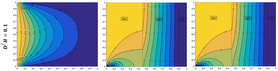
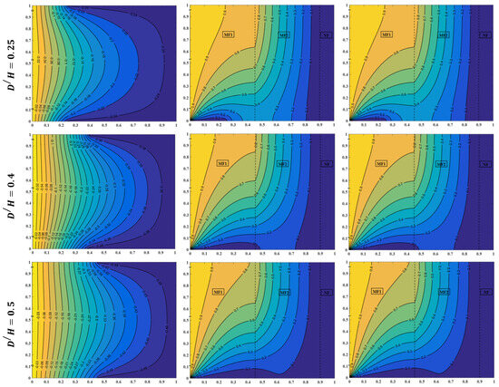
Figure 4.
Streamlines (left), fluid isotherms (middle), and solid isotherms (right) for different values of inlet to outlet aspect ratio at , , , and .
The influences of the Reynolds number and solid copper nanoparticle volume fractions for the uniform heating left sidewall case on the streamlines and isotherm contour lines have been plotted for , , and , as illustrated in Figure 5. For certain Reynolds number values, an increasing nanoparticle fraction effectuates an increase in the fluid temperature for both layers of metal foam. This increase is because of the enhanced water–copper nanofluid’s effective thermal properties, specifically the thermal conductivity, which is mainly responsible for transferring heat inside the enclosure. Therefore, a nanoparticle volume fraction of is a reliant value of fraction for the remaining case results in the present study. Moreover, Figure 5 clearly depicts a reduction in the fluid temperature as the Reynolds number is increased at certain points in the cavity. For , isotherms are controlled almost by conduction and natural convection, and, hence, a larger area is occupied by higher temperature, which makes it suitable for heating applications. When , forced convection currents take place, but, still, they are not large enough to decrease the high-temperature area inside the enclosure. As is further increased to , the effect of forced convection becomes more evident and a clear decrease in temperature at a certain location, as compared with the last two values of the Reynolds number. This temperature reduction makes more appropriate for cooling requests.
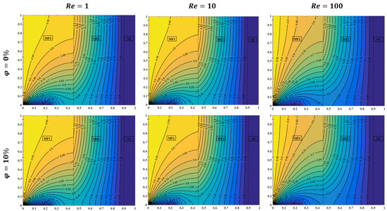
Figure 5.
Fluid isotherms for different values of Reynolds number and nanoparticle volume fraction at , , and .
The behavior of the average Nusselt number for fluid and solid phases under the effects of Reynolds number, inlet-to-outlet aspect ratio, and nanoparticle volume fraction at and is plotted in Figure 6 and Figure 7, respectively. It is obviously seen from Figure 6 that the fluid Nusselt number increases monotonically as the Reynolds number, vent aspect ratio, and solid nanoparticle fraction are increased. Increasing the Reynolds number from to at certain values of nanofluid volume fractions and vent dimension aspect ratios leads to an increase of in the fluid Nusselt number. This increase is due to the higher forced convection currents occurring as a result of high fluid velocity at higher values of Reynolds number, which tends to dominate the convective heat transfer mode near the left cavity sidewall. On the other hand, raising the inlet-to-outlet aspect ratio from to at specific values of and results in a rise of in the fluid Nusselt number. The reason behind this amplification is owing to the larger quantity of fluid entering the cavity; such a value of the Reynolds number () causes a higher temperature difference between the hot sidewall and fluid passing through metal foam, in addition to the fluid velocity, which tends towards intensifying convection heat transfer currents relative to the conduction heat mode. Further, the fluid Nusselt number increases by as the solid nanoparticle fraction increases from to for the case of and , and this amplification is attributable to the increasing amount of copper nanoparticles in water-based fluid. That is outstanding to the alteration in the fluid-saturated effective thermophysical properties especially, increasing thermal conductivity and decreasing heat capacity, which provides a rise in transferring heat inside the enclosure. This rise in heat transfer tends towards an increase in the temperature gradient near the hot wall and, thus, an increasing Nusselt number is obtained. In Figure 7, the same qualitative trend of increase is obtained for the solid-phase Nusselt number when the Reynolds number and inlet and outlet port aspect ratio are augmented, while there is no significant change produced in the solid Nusselt number value as the nanoparticle fraction is amplified. For and changed from to , the solid Nusselt number is also increased by , and for and , it is altered from to , and the solid Nusselt number is amplified by . This behavior is attributed to the same reason mentioned for the fluid Nusselt number. However, the reason behind the unaltered nanoparticle fraction variation is that enhancing the fluid’s effective thermal properties does not significantly affect the convection and conduction heat transfer in the metal foam solid domain, which leads to no change in the solid Nusselt number value.
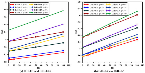
Figure 6.
Fluid-phase Nusselt number variations with Reynolds number for various values of inlet-to-outlet aspect ratio and nanoparticle fraction at and .
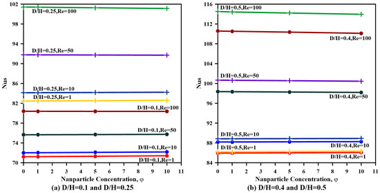
Figure 7.
Solid-phase Nusselt number variations with Reynolds number for various values of inlet-to-outlet aspect ratio and nanoparticle fraction at and .
4.2. Effect of Sinusoidal Frequency and Amplitude
The temperature distribution for non-unform heating along the left cavity wall is displayed in Figure 8 for different values of frequency and amplitude at certain offset temperatures. It is seen from this figure that temperature fluctuates around the offset temperature , which is taken as the uniform heating temperature. This fluctuation gives an indication of heating and cooling on the hot wall as a simulation for practical applications, like the cooling of electronic devices, equipment, nuclear waste management, chemical reactors, and chemical equipment.
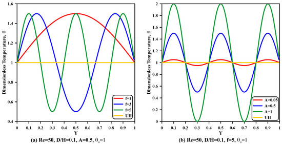
Figure 8.
Dimensionless hot left sidewall temperature variations with distance along wall for various frequencies (left) and amplitudes (right) at , , and .
The effects of sinusoidal heating frequency and amplitude alteration on fluid-phase isothermal lines are investigated and illustrated in Figure 9 at , , , and . It is obvious from this figure that a rising frequency from to at a specific amplitude value leads to an irrelevant alteration in fluid isotherms, because, by referring to Figure 8b, the hot non-uniform temperature at this amplitude (red line) is approximately the same as the uniform heating temperature (yellow line). However, when the amplitude is enlarged to and then to , increasing frequency results in regions on the left wall with heating and cooling temperature for which fluid isotherms take a sinusoidal shape near the left sidewall. Also, these isotherm lines are altered by the cooling temperature, which tends towards a larger area inside the cavity with lower temperature values. Therefore, the selection of frequency and amplitude can be conducted according to the required application.
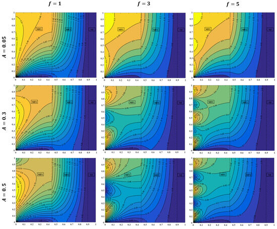
Figure 9.
Fluid isotherms for different values of frequency and amplitude at , , , , and .
From this point of view, accordingly, the local Nusselt number for the fluid and solid phases is sinusoidally fluctuated along the hot sidewall for the non-uniform case, as demonstrated in Figure 10 and Figure 11. Examining these two figures, it can be deduced that both the fluid and solid local Nusselt number behavior of non-uniform heating with and is similar to their comportment for uniform heating. This similar trend occurs due to the insignificant fluctuation change in the temperature gradient near the wall for these two values of frequency and amplitude and the constant uniform heating case. Also, it is well known that the Nusselt number is altered mainly by the temperature gradient, which is obviously shown for larger amplitude ( and ) and frequency ( and ) values that give a sinusoidal action for the local Nusselt number. By referring to Figure 9, it is clearly shown that there is a temperature gradient fluctuation near the hot wall, which, accordingly, results in local Nusselt number fluctuation, as stated in Equations (32) and (33). Additionally, the sinusoidal fluctuation in the temperature gradient produces some positional locations with a higher temperature gradient relative to other positions in sinusoidal behavior when frequency and amplitude are increased to higher values.
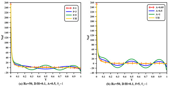
Figure 10.
Fluid phase local Nusselt number variations along left hot wall for amplitude and frequency at , , , , and .
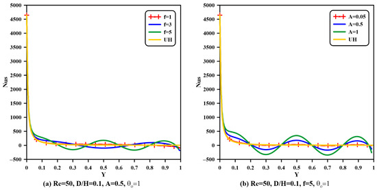
Figure 11.
Solid phase local Nusselt number variations along left hot wall for amplitude and frequency at , , , , and .
The variation in the average Nusselt number for fluid and solid phases with inlet and outlet vent aspect proportions for different relevant parameters is exemplified in Figure 12 and Figure 13. It is obvious from these two figures that increasing port aspect ratios and Reynolds numbers lead to an intensification in the average Nusselt numbers of two phases at definite frequency and amplitude values. This is attributed to the escalating streamlines as a result of increasing the Reynolds number, and, thus, the velocity values are increased, increasing the convection currents between saturated fluid and the solid part of the porous media inside the cavity, which results in a higher temperature gradient near the wall. Moreover, as the inlet-to-outlet vent aspect ratio is increased, there is a freer flow of fluid, with no constraint and impedance as this ratio is raised from to , thus increasing convection heat currents in the enclosure. As a result, when , , and , the fluid-phase Nusselt number is increased by as is raised from to , and also, the solid-phase Nusselt number is enhanced by the same percentage value. Additionally, both fluid- and solid-phase Nusselt numbers amplify by for the case of , , and when the Reynolds number extends from to . In addition, for all values of Reynolds number and aspect ratios, for both phases, the average Nusselt numbers are magnified once the amplitude is increased and the frequency is raised, specifically when and . This behavior is owing to the presence of a higher temperature gradient near the wall, which generates superior convection heat currents that generate higher Nusselt number values. Also, it can be noticed from Figure 12 and Figure 13 that the Nusselt number remains constant when the frequency is raised from to , specifically when the vent aspect ratio is greater than . The reason behind this behavior is that larger opening vents result in a reduced frequency alteration on the temperature gradient near the cavity wall. This is attributed to the increasing amount of fluid entering the cavity, which diminishes the temperature gradient fluctuation effect when the sinusoidal frequency is increased.
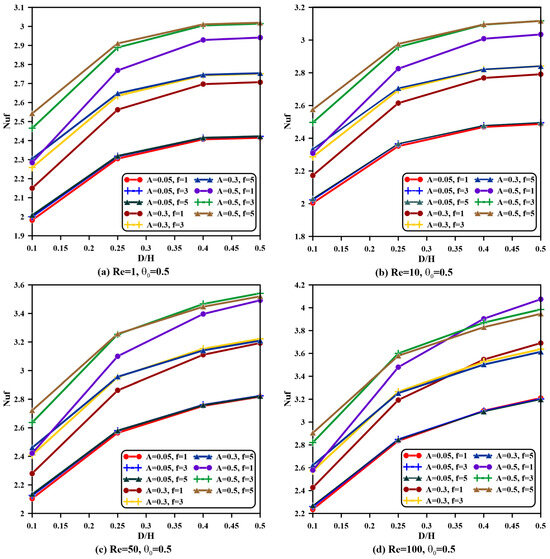
Figure 12.
Fluid phase average Nusselt number variations with inlet to outlet aspect ratio for Reynolds number, amplitude, and frequency at , , and .
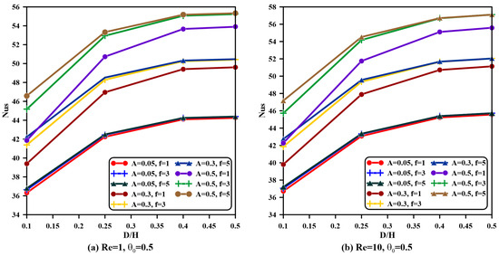
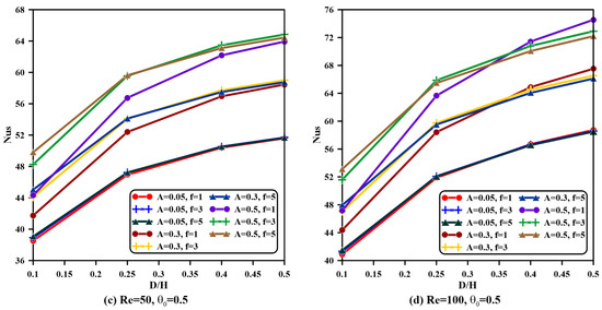
Figure 13.
Solid phase average Nusselt number variations with inlet to outlet aspect ratio for Reynolds number, amplitude, and frequency at , , and .
4.3. Effect of Sinusoidal Offset Temperature
When the sinusoidal offset temperature is increased to , the same performance is achieved for fluid temperature contours, as clarified in Figure 14 at , , , and . At a small value of amplitude (), fluid isotherm lines remain unchanged once the frequency is enlarged. But, as the amplitude is improved to and then to , isothermal lines near the sidewall are also formed sinusoidally when the frequency is amplified but with higher values because an increasing offset temperature leads to higher energy supplied during non-uniform heating. Generally, the isotherm’s sinusoidal shape behavior can be attributed to the same physical reasons mentioned for Figure 9.
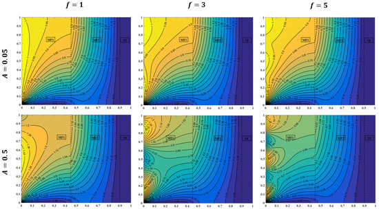
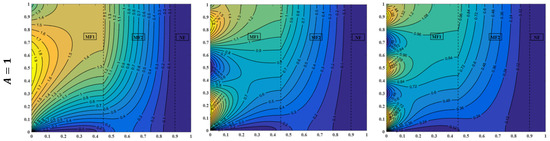
Figure 14.
Fluid isotherms for different values of frequency and amplitude , , , , and .
In Figure 15 and Figure 16, metal foam’s fluid- and solid-phase average Nusselt number variations with the vent aspect ratio, Reynolds number, frequency, and amplitude are demonstrated for . Examining these two figures, it can be deduced that average Nusselt number actions are similar to those represented in Figure 12 and Figure 13 for the identical physical explanations mentioned before. For the case of , , and , the fluid-phase Nusselt number is improved by as is raised from to , and also, the solid-phase Nusselt number develops by the same percentage value but with higher values of Nusselt number and temperature. In addition, both metal foam phase Nusselt numbers amplify by for the case of , , and when the Reynolds number enlarges from to but with higher temperature and average Nusselt number values. Therefore, the offset temperature can be settled corresponding to the application’s demand.
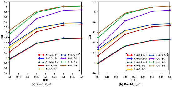
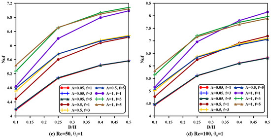
Figure 15.
Fluid phase average Nusselt number variations with inlet to outlet aspect ratio for Reynolds number, amplitude, and frequency at , , and .
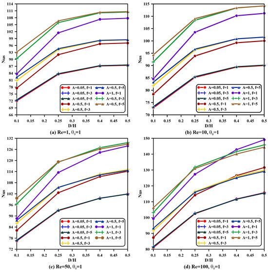
Figure 16.
Solid phase average Nusselt number variations with inlet to outlet aspect ratio for Reynolds number, amplitude, and frequency at , , and .
4.4. Effect of Outlet Port Opening Location
Three locations for the outlet opening port were investigated in the present work, namely the left (), middle (), and right (). For these locations, streamlines and fluid isotherm contours for Reynolds number values of , , , and , , , and are illustrated in Figure 17. It is obvious from this figure that streamlines are more intensified at the upper-left cavity corner when the outlet opening vent is translated from the left location to the middle and then to the right of the enclosure’s upper wall. As a result, a higher fluid velocity value is found according to the magnitude of the Reynolds number, which results in the domination of a forced convection regime rather than the weak natural convection region inside the cavity. Also, it can be noticed that the streamline flow pattern is regular, without any rotating vortices, and this is because a scrawny natural convection regime weakens the strength vorticity within the enclosure. From the fluid temperature contours, it is observed that temperature values differ only in regions near the hot wall and at Reynolds numbers and . In contrast to other values of Reynolds numbers, temperatures remain constant when the outlet port location is changed. This is owing to the presence of the metal foam of the first layer (MF1), for which saturated fluid needs higher velocities to move through porous media voids. Consequently, isotherm lines in the second layer (MF2) of higher PPI metal foam remain the same for all studied Reynolds number ranges because this layer has less void area, and fluid moves slowly through it; hence, changing the outlet port location has no effect through this layer.
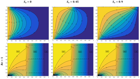
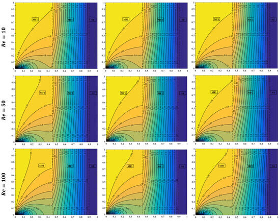
Figure 17.
Streamlines and fluid isotherms for different values of outlet port location left (), middle (), and right () and Reynolds number at , , and .
For the middle outlet vent location (), the uniform heating () average Nusselt number of the fluid and solid phases is depicted in Figure 18 to examine the outcome of varying relevant parameters. These parameters include the Reynolds number, inlet and outlet port aspect ratio, and solid nanoparticle volume fraction. From this figure, it is clearly clarified that the Nusselt number behavior for this outlet location typically has the same performance of that for the left outlet port location mentioned in Figure 6 and Figure 7. However, the temperature gradient of the middle location has dissimilar values to that of the left location, as clarified in Figure 17, especially at high Reynolds numbers ( and ). Thus, raising the inlet-to-outlet aspect ratio from to at certain values of and results in a rise of in the fluid Nusselt number for the left outlet location, whereas the rise becomes for the middle location. Similarly, for and altered from to , the solid Nusselt number is amplified by for the left position and increased by for the middle position.
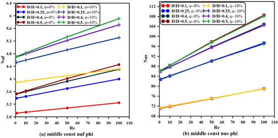
Figure 18.
Fluid and solid Nusselt number variations with Reynolds number for various values of vents aspect ratio and nanoparticle fraction at , , and .
In Figure 19 and Figure 20, the fluid and solid metal foam phases’ average Nusselt number variance with the Reynolds number, vent aspect ratio, and frequency is plotted for non-uniform heating at and . The performance of the Nusselt number in this figure is also similar to the same case of the left outlet location illustrated in Figure 15 and Figure 16, though with different temperature gradient and Nusselt number values. For the case of , and , when the Reynolds number increases from to , both the fluid- and solid-phase Nusselt numbers are amplified by but with higher temperature and Nusselt number values.
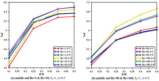
Figure 19.
Fluid Nusselt number variations with vents aspect ratio for various values of Reynolds number and frequency at , , , and .
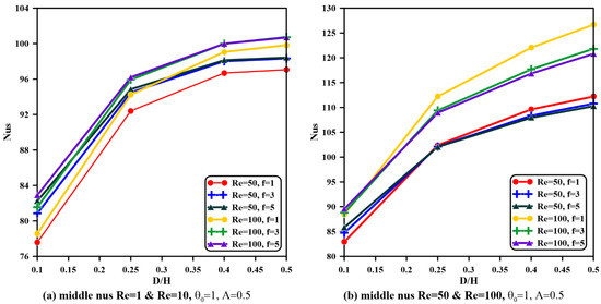
Figure 20.
Solid Nusselt number variations with vents aspect ratio for various values of Reynolds number and frequency at , , , and .
With the intention of investigating the effect of varying outlet port positions on the fluid and solid average Nusselt number, Figure 21 and Figure 22 are presented for uniform and non-uniform heating, respectively. In Figure 21, it is observable that the fluid-phase Nusselt number remains approximately constant as the outlet port is shifted towards the right for and , while for a higher Reynolds number, it decreases slightly as the outlet vent location is translated from the left to the middle. Then, the fluid Nusselt number sees an almost constant value between the middle and right shift in the outlet vent. This can be attributed to the isotherm behavior and temperature gradient values, as mentioned in Figure 17. The same action can be deduced for the solid-phase Nusselt number as the outlet vent position is altered. Moreover, the inclusion of nanomaterial in fluid induces an increase in temperature, owing to the increase in the thermal conductivity of nanofluid, and, thus, a higher heat transfer rate is generated, which results in a higher temperature gradient. This is the main reason behind the increasing fluid-phase average Nusselt number as the solid nanoparticle volume fraction is intensified. However, it is observable from Figure 21 that the solid-phase Nusselt number does not change when the nanomaterial fraction is raised and remains constant, especially at and , for the same reason revealed in Figure 7. For the non-uniform heating case, higher Nusselt number values of both metal foam phases are attained at and , as illustrated in Figure 22. Also, the same Nusselt number behavior as that of the constant heating case is achieved when increasing the Reynolds number and shifting the outlet vent location from the left corner towards the right corner of the cavity’s upper wall. In addition, Figure 22 reveals that increasing frequency tends to increase the average Nusselt number, retaining the same actions when altering the outlet port location for the same explanations stated formerly.
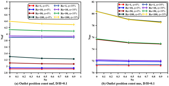
Figure 21.
Fluid and solid phase Nusselt number variations with outlet port location for various values of Reynolds number and nanoparticle fraction at and .
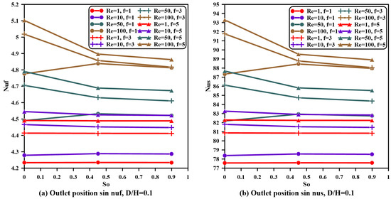
Figure 22.
Fluid and solid Nusselt number variations with outlet port location for various values of Reynolds number and frequency at , , , and .
5. Conclusions
In the present work, two layers of copper metal foam with different PPI values and equal porosities confined in a square vented cavity and saturated with copper–water nanofluid with different particle volume fractions are investigated numerically by using the finite volume method. The cavity’s left sidewall is subjected to two types of heating, uniform (constant temperature) and non-uniform (sinusoidal temperature profile), and the outlet opening port location is altered along the top cavity wall in three positions: left corner, middle, and right corner. The effect of relevant parameters is examined, including the Reynolds number, inlet and outlet vent aspect ratios, nanoparticle volume fractions, outlet vent opening location, sinusoidal offset temperature, and frequencies and amplitudes of the sinusoidal temperature profile. This physical geometry can be utilized in many practical applications, e.g., solar energy, chemical and nuclear reactors, and convective drying. The main achievements of the current numerical problem are highlighted below:
- Streamlines imply higher values and fluid, and solid isotherms have smaller regions of high temperature near the left wall as the inlet and outlet vent aspect ratio is increased.
- Fluid and solid isothermal lines in the first metal foam layer MF1 are more curved, and the thermal boundary layer is distinct and indicates vigorous convection currents, while isotherms in the second metal foam layer MF2 are approximately straight lines, suggesting that the conduction heat transfer mode is dominant in this region.
- Increasing the nanoparticle volume fraction effectuates an increase in fluid temperature for both layers of metal foam.
- The increase in the Reynolds number causes a reduction in the fluid and solid temperature.
- The fluid-phase average Nusselt number increases monotonically as the Reynolds number, inlet and outlet vent aspect ratio, and solid nanoparticle fraction volume are increased.
- The solid-phase average Nusselt number increases as the Reynolds number and inlet and outlet vent aspect ratio are raised and remains constant for nanoparticle fraction variation.
- For non-uniform heating, isothermal lines take a sinusoidal shape near the hot wall, and increasing frequency results in regions with heating and cooling temperatures, which results in a larger area inside the cavity with lower temperature values.
- The increasing port aspect ratio and Reynolds number lead to an intensifying fluid and solid average Nusselt number at definite frequency and amplitude values.
- For all values of the Reynolds number and aspect ratios, both phases’ average Nusselt numbers are magnified once the amplitude is increased and frequency is raised, specifically when and . However, the Nusselt number remains constant when the frequency is raised from to , specifically when the vent aspect ratio is greater than .
- Sinusoidal isothermal lines are also formed sinusoidally near the sidewall as the offset temperature and frequency are amplified but with higher values.
- When the offset temperature is increased, the same trend is obtained for fluid- and solid-phase Nusselt number variations with the vent aspect ratio, Reynolds number, frequency, and amplitude but with higher values of Nusselt number and temperature.
- Streamlines are more intensified at the upper-left cavity corner when the outlet opening vent is translated from the left location to the middle and then to the right of the enclosure’s upper wall.
- As the Reynolds number values are and , the temperature values differ only in regions near the hot wall, in contrast to other values of the Reynolds number, where the temperatures remain constant when the outlet port location is changed.
- For the middle outlet vent location, the uniform heating fluid- and solid-phase average Nusselt number behavior typically has the same performance of that for the left outlet port location, though with different temperature gradient and Nusselt number values.
- In uniform and non-uniform heating cases, the fluid- and solid-phase Nusselt number remains approximately constant as the outlet port is shifted towards the right for and , and for a higher Reynolds number, it decreases slightly as the outlet vent location is translated from the left to the middle and then has an almost constant value between the middle and right shift in the outlet vent.
- Increasing frequency tends to raise the average Nusselt number, retaining the same behaviors when altering the outlet port from the left to the right position.
Author Contributions
Conceptualization, A.J.H.; methodology, L.F.A.; validation, A.J.H.; formal analysis, A.J.H.; investigation, L.F.A.; writing—review and editing, A.J.H.; writing—original draft preparation, L.F.A.; supervision, A.J.H.; and funding acquisition A.J.H. and L.F.A. All authors have read and agreed to the published version of the manuscript.
Funding
This work was not financially supported by any organization, and fees were paid by the authors.
Data Availability Statement
Data supporting the reported results can be provided by the authors.
Acknowledgments
The authors gratefully acknowledge all collogues for their co-operation.
Conflicts of Interest
The authors declare no conflicts of interest.
Abbreviations
The following abbreviations are used in this manuscript:
| MF1 | First Metal Foam |
| MF2 | Second Metal Foam |
| NF | Nanofluid |
| PPI | Pores Per Inch |
| UH | Uniform Heating |
References
- Saeidi, S.M.; Khodadadi, J.M. Forced Convection in a Square Cavity with Inlet and Outlet Ports. Int. J. Heat Mass Transf. 2006, 49, 1896–1906. [Google Scholar] [CrossRef]
- Wang, C.; Li, Z.; Xu, P.; Hou, Y.; Tan, D.; Li, L. Collision Modeling Approach and Transient Response Mechanism of Ring-Ribbed Cylindric Shells for Underwater Vehicles. Appl. Math. Model. 2025, 141, 115923. [Google Scholar] [CrossRef]
- Xu, P.; Li, Q.; Wang, C.; Li, L.; Tan, D.; Wu, H. Interlayer Healing Mechanism of Multipath Deposition 3D Printing Models and Interlayer Strength Regulation Method. J. Manuf. Process 2025, 141, 1031–1047. [Google Scholar] [CrossRef]
- Gu, C.; Li, Y.; Zheng, L.; Gu, Y.; Li, L.; Zheng, G. Study on the Dynamic Characteristics of the Gear Lubrication Flow Field with Baffles and Optimization Design Strategies. Lubricants 2025, 13, 143. [Google Scholar] [CrossRef]
- Lin, Q.; Li, Q.; Xu, P.; Zheng, R.; Bao, J.; Li, L.; Tan, D. Transport Mechanism and Optimization Design of LBM–LES Coupling-Based Two-Phase Flow in Static Mixers. Processes 2025, 13, 1666. [Google Scholar] [CrossRef]
- Alkinani, I.H.; Ali, L.F. Natural Convection in Annulus between Two Concentric Cylinders Partially Filled with Metal Foam Distributed with New Suggested Design. IOP Conf. Ser. Earth Environ. Sci. 2022, 1, 012032. [Google Scholar] [CrossRef]
- Abdulwahed, A.S.; Ali, L.F. Numerical Investigation of Natural Convection in a Square Enclosure Partially Filled with Horizontal Layers of a Porous Medium. Heat Transf. 2023, 52, 874–889. [Google Scholar] [CrossRef]
- Zachi, F.J.; Ali, L.F. Experimental Study of Natural Convection Heat Transfer on an Enclosure Partially Filled Porous Medium Heated from below by Constant Heat Flux. AIP Conf. Proc. 2023, 2651, 050002. [Google Scholar] [CrossRef]
- Mahmoudi, Y.; Hooman, K.; Vafai, K. Convective Heat Transfer in Porous Media, 1st ed.; CRC Press: Boca, Raton, FL, USA, 2020. [Google Scholar] [CrossRef]
- Nield, D.A.; Bejan, A. Convection in Porous Media; Springer International Publishing: Cham, The Switzerland, 2017. [Google Scholar] [CrossRef]
- Kaviany, M. Principles of Heat Transfer in Porous Media; Springer: New York, NY, USA, 1995. [Google Scholar] [CrossRef]
- Choi, S.U.S.; Eastman, J.A.; Eastman, J.A. Enhancing Thermal Conductivity of Fluids with Nanoparticles, Developments and Application of Non-Newtonian Flows. In Proceedings of the ASME International Mechanical Engineering Congress & Exposition, San Francisco, CA, USA, 12–17 November 1995. [Google Scholar]
- Daungthongsuk, W.; Wongwises, S. A Critical Review of Convective Heat Transfer of Nanofluids. Renew. Sustain. Energy Rev. 2007, 11, 797–817. [Google Scholar] [CrossRef]
- Tien, H.-C.; Chiang, K.-S. Non-Darcy Flow and Heat Transfer in a Porous Insulation with Infiltration. J. Mar. Sci. Technol. 2009, 7, 8. [Google Scholar] [CrossRef]
- Mahmud, S.; Pop, I. Mixed Convection in a Square Vented Enclosure Filled with a Porous Medium. Int. J. Heat Mass Transf. 2006, 49, 2190–2206. [Google Scholar] [CrossRef]
- Ghazanfarian, J.; Abbassi, A.B.B.A.S. Mixed Convection in a Square Cavity Filled with a Porous Medium and Different Exit Port Position. J. Porous Media 2007, 10, 701–718. [Google Scholar] [CrossRef]
- Krishna Murthy, S.V.S.S.N.; Kumar, B.V.R. Non-Darcy Mixed Convection in a Porous Square Enclosure under Suction/Injection Effects with a Non-Isothermal Vertical Wall. Numer. Heat Transf. A Appl. 2010, 57, 580–602. [Google Scholar] [CrossRef]
- Krishna Murthy, S.V.S.S.N.; Kumar, B.V.R. Darcy Mixed Convection in a Fluid Saturated Square Porous Enclosure under Multiple Suction Effect. Int. J. Numer. Methods Heat Fluid. Flow 2011, 21, 602–617. [Google Scholar] [CrossRef]
- Rathish Kumar, B.V.; Krishna Murthy, S.V.S.S.N.V.G. Mixed Convection in a Non-Darcian Fluid Saturated Square Porous Enclosure under Multiple Suction Effect. Int. J. Heat Mass Transf. 2010, 53, 5764–5773. [Google Scholar] [CrossRef]
- Zhao, F.Y.; Liu, D.; Wang, H.Q.; Kou, G.X.; Tang, G.F. Free Heat and Mass Transfer in a Porous Enclosure with Side Vents. Dry. Technol. 2011, 29, 91–104. [Google Scholar] [CrossRef]
- Behzadi, T.; Shirvan, K.M.; Mirzakhanlari, S.; Sheikhrobat, A.A. Numerical Simulation on Effect of Porous Medium on Mixed Convection Heat Transfer in a Ventilated Square Cavity. Procedia Eng. 2015, 127, 221–228. [Google Scholar] [CrossRef][Green Version]
- Ali, L.F. Natural and Mixed Convection in Square Vented Enclosure Filled with Metal Foam. J. Eng. 2015, 21, 60–79. [Google Scholar] [CrossRef]
- Bhuiyan, A.A.; Banna, M.H.; Barna, S.F.; Amin, M.R.; Sadrul Islam, A.K.M. Numerical Modelling of Thermal Characteristics in a Microstructure Filled Porous Cavity with Mixed Convection. Int. J. Heat Mass Transf. 2016, 93, 464–476. [Google Scholar] [CrossRef]
- Ghalambaz, M.; Moattar, F.; Karbassi, A.; Sheremet, M.A.; Pop, I. Triple-Diffusive Mixed Convection in a Porous Open Cavity. Transp. Porous Media 2017, 116, 473–491. [Google Scholar] [CrossRef]
- Hazra, C.; Biswas, N.; Manna, N.K. Thermal Magneto-Hydrodynamics in a Ventilated Porous Enclosure. Sādhanā 2020, 45, 224. [Google Scholar] [CrossRef]
- Ataei-Dadavi, I.; Chakkingal, M.; Kenjeres, S.; Kleijn, C.R.; Tummers, M.J. Experiments on Mixed Convection in a Vented Differentially Side-Heated Cavity Filled with a Coarse Porous Medium. Int. J. Heat Mass Transf. 2020, 149, 119238. [Google Scholar] [CrossRef]
- Alawee, W.H.; Al-Sumaily, G.F.; Dhahad, H.A.; Thompson, M.C. Numerical Analysis of Non-Darcian Mixed Convection Flows in a Ventilated Enclosure Filled with a Fluid-Saturated Porous Medium. Therm. Sci. Eng. Prog. 2021, 24, 100922. [Google Scholar] [CrossRef]
- Sheremet, M.A.; Pop, I.; Ishak, A. Double-Diffusive Mixed Convection in a Porous Open Cavity Filled with a Nanofluid Using Buongiorno’s Model. Transp. Porous Media 2015, 109, 131–145. [Google Scholar] [CrossRef]
- Ahmed, S.E. Caputo Fractional Convective Flow in an Inclined Wavy Vented Cavity Filled with a Porous Medium Using Al2O3-Cu Hybrid Nanofluids. Int. Commun. Heat Mass Transf. 2020, 116, 104690. [Google Scholar] [CrossRef]
- Ullah, N.; Nadeem, S.; Saleem, A. Finite Element Analysis of Convective Nanofluid Equipped in Enclosure Having Both Inlet and Outlet Zones. J. Taiwan. Inst. Chem. Eng. 2020, 113, 428–441. [Google Scholar] [CrossRef]
- Hussain, S.; Öztop, H.F.; Alsharif, A.M.; Ertam, F. Mixed Bioconvection of Nanofluid of Oxytactic Bacteria through a Porous Cavity with Inlet and Outlet under Periodic Magnetic Field Using Artificial Intelligence Based on LightGBM Algorithm. Therm. Sci. Eng. Prog. 2024, 50, 102589. [Google Scholar] [CrossRef]
- Costa, V.A.F.; Oliveira, M.S.A.; Sousa, A.C.M. Numerical Simulation of Non-Darcian Flows through Spaces Partially Filled with a Porous Medium. Comput. Struct. 2004, 82, 1535–1541. [Google Scholar] [CrossRef]
- Shuja, S.Z.; Yilbas, B.S.; Khan, S.M.A. Flow Subjected to Porous Blocks in the Cavity: Consideration of Block Aspect Ratio and Porosity. Chem. Eng. J. 2008, 139, 84–92. [Google Scholar] [CrossRef]
- Shuja, S.Z.; Yilbas, B.S.; Kassas, M. Flow over Porous Blocks in a Square Cavity: Influence of Heat Flux and Porosity on Heat Transfer Rates. Int. J. Therm. Sci. 2009, 48, 1564–1573. [Google Scholar] [CrossRef]
- Moraga, N.O.; Sánchez, G.C.; Riquelme, J.A. Unsteady Mixed Convection in a Vented Enclosure Partially Filled with Two Non-Darcian Porous Layers. Numer. Heat Transf. A Appl. 2010, 57, 473–495. [Google Scholar] [CrossRef]
- Gibanov, N.S.; Sheremet, M.A.; Ismael, M.A.; Chamkha, A.J. Mixed Convection in a Ventilated Cavity Filled with a Triangular Porous Layer. Transp. Porous Media 2017, 120, 1–21. [Google Scholar] [CrossRef]
- Chakravarty, A.; Biswas, N.; Ghosh, K.; Manna, N.K.; Mukhopadhyay, A.; Sen, S. Impact of Side Injection on Heat Removal from Truncated Conical Heat-Generating Porous Bed: Thermal Non-Equilibrium Approach. J. Therm. Anal. Calorim. 2021, 143, 3741–3760. [Google Scholar] [CrossRef]
- Chakravarty, A.; Datta, P.; Ghosh, K.; Sen, S.; Mukhopadhyay, A. Mixed Convective Heat Transfer in an Enclosure Containing a Heat-Generating Porous Bed under the Influence of Bottom Injection. Int. J. Heat Mass Transf. 2018, 117, 645–657. [Google Scholar] [CrossRef]
- Hireche, Z.; Himrane, N.; Nasseri, L.; Hamrioui, Y.; Ameziani, D.E. Analysis of Thermal Performances in a Ventilated Room Using LBM-MRT: Effect of a Porous Separation. Computation 2022, 10, 4. [Google Scholar] [CrossRef]
- Hireche, Z.; Himrane, N.; Nasseri, L.; Ameziani, D.E. Effect of Porous Partition Height on Thermal Performance of a Ventilated Cavity Using LBM-MRT. E3S Web Conf. 2021, 321, 02007. [Google Scholar] [CrossRef]
- Selimefendigil, F.; Öztop, H.F. Thermal Management and Modeling of Forced Convection and Entropy Generation in a Vented Cavity by Simultaneous Use of a Curved Porous Layer and Magnetic Field. Entropy 2021, 23, 52. [Google Scholar] [CrossRef]
- Kolsi, L.; Selimefendigil, F.; Omri, M.; Rmili, H.; Ayadi, B.; Maatki, C.; Alshammari, B.M. CFD Study of MHD and Elastic Wall Effects on the Nanofluid Convection Inside a Ventilated Cavity Including Perforated Porous Object. Mathematics 2023, 11, 695. [Google Scholar] [CrossRef]
- Messaoud, H.; Adel, S.; Ouerdia, O. Mixed Convection Heat Transfer of a Nanofluid in a Square Ventilated Cavity Separated Horizontally by a Porous Layer and Discrete Heat Source. Arch. Thermodyn. 2023, 44, 87–114. [Google Scholar] [CrossRef]
- Baranovskii, E.S. The Stationary Navier–Stokes–Boussinesq System with a Regularized Dissipation Function. Math. Notes 2024, 115, 670–682. [Google Scholar] [CrossRef]
- Xu, Z.G.; Gong, Q. Numerical Investigation on Forced Convection of Tubes Partially Filled with Composite Metal Foams under Local Thermal Non-Equilibrium Condition. Int. J. Therm. Sci. 2018, 133, 1–12. [Google Scholar] [CrossRef]
- Xu, H.J.; Gong, L.; Zhao, C.Y.; Yang, Y.H.; Xu, Z.G. Analytical Considerations of Local Thermal Non-Equilibrium Conditions for Thermal Transport in Metal Foams. Int. J. Therm. Sci. 2015, 95, 73–87. [Google Scholar] [CrossRef]
- Wang, B.; Hong, Y.; Hou, X.; Xu, Z.; Wang, P.; Fang, X.; Ruan, X. Numerical Configuration Design and Investigation of Heat Transfer Enhancement in Pipes Filled with Gradient Porous Materials. Energy Convers. Manag. 2015, 105, 206–215. [Google Scholar] [CrossRef]
- Ghashim, S.L. A Mathematical Analysis of Nanoparticles on Heat Transfer in a Circular Pipe. Case Stud. Therm. Eng. 2021, 28, 101524. [Google Scholar] [CrossRef]
- Alazmi, B.; Vafai, K. Constant Wall Heat Flux Boundary Conditions in Porous Media under Local Thermal Non-Equilibrium Conditions. Int. J. Heat Mass Transf. 2002, 45, 3071–3087. [Google Scholar] [CrossRef]
- Al-Farhany, K.; Abdulsahib, A.D. Study of Mixed Convection in Two Layers of Saturated Porous Medium and Nanofluid with Rotating Circular Cylinder. Prog. Nucl. Energy 2021, 135, 103723. [Google Scholar] [CrossRef]
- Xu, Z.G.; Qin, J.; Zhou, X.; Xu, H.J. Forced Convective Heat Transfer of Tubes Sintered with Partially-Filled Gradient Metal Foams (GMFs) Considering Local Thermal Non-Equilibrium Effect. Appl. Therm. Eng. 2018, 137, 101–111. [Google Scholar] [CrossRef]
- Arasteh, H.; Mashayekhi, R.; Toghraie, D.; Karimipour, A.; Bahiraei, M.; Rahbari, A. Optimal Arrangements of a Heat Sink Partially Filled with Multilayered Porous Media Employing Hybrid Nanofluid. J. Therm. Anal. Calorim. 2019, 137, 1045–1058. [Google Scholar] [CrossRef]
- Patankar, S.V. Numerical Heat Transfer and Fluid Flow; Taylor & Francis Publishers: New York, NY, USA, 1980. [Google Scholar] [CrossRef]


Disclaimer/Publisher’s Note: The statements, opinions and data contained in all publications are solely those of the individual author(s) and contributor(s) and not of MDPI and/or the editor(s). MDPI and/or the editor(s) disclaim responsibility for any injury to people or property resulting from any ideas, methods, instructions or products referred to in the content. |
© 2025 by the authors. Licensee MDPI, Basel, Switzerland. This article is an open access article distributed under the terms and conditions of the Creative Commons Attribution (CC BY) license (https://creativecommons.org/licenses/by/4.0/).