Article

Design and Experimentation of Variable-Density Damping Materials Based on Topology Optimization

1
College of Automobile and Transportation Engineering, Guangdong Polytechnic Normal University, Guangzhou 510665, China
2
Guangdong LIK Industry Co., Ltd., Dongguan 430048, China
*
Author to whom correspondence should be addressed.
Processes 2025, 13(7), 2276; https://doi.org/10.3390/pr13072276 (registering DOI)
Submission received: 25 June 2025 / Revised: 12 July 2025 / Accepted: 15 July 2025 / Published: 17 July 2025

Abstract

In engineering structures, damping materials are an effective way to improve vibration characteristics, but they can significantly increase the weight and cost of the structure. In this study, based on the variable density topology optimization algorithm, combined with finite element simulation and experimental validation, the vibration damping performance of a composite structure with steel plate and damping material is optimized. With the objective of minimizing the resonance response and the constraint of damping material volume, the material distribution of the damping layer is optimized, and the amount of damping material used is successfully reduced by 31.2%. By building a test rig and comparing the vibration responses under the three working conditions of no damping, full damping coverage, and optimized damping, the effectiveness of the optimization strategy is verified, and a significant reduction in vibration response is achieved. This study provides an innovative solution for lightweight design and cost control in engineering.

1. Introduction

In contemporary engineering practices, especially in automotive applications where thin-walled structures (e.g., body panels, chassis components) are prone to vibration-induced noise and fatigue, effectively mitigating and controlling vibration issues is critical for NVH performance. Damping materials are one of the central means of achieving vibration control. These materials are usually viscoelastic polymers or rubber-based composites, which are able to convert the mechanical energy of structural vibration into thermal energy through their unique viscoelastic energy dissipation mechanism, thus significantly reducing vibration amplitude and noise levels [1]. However, traditional full-coverage damping treatments significantly increase weight and cost, contradicting lightweight goals and cost-efficiency requirements. Therefore, optimizing the structural layout of damping materials to achieve lightweighting and maximize cost-effectiveness [2,3,4] has become an urgent engineering challenge.
Addressing the aforementioned focus, scholars worldwide have conducted extensive research. For instance, Zhang [5] proposed a topology optimization method for designing composite damping materials with high broadband damping, achieving a broadband damping effect through the rational combination of two damping materials. Zhao [6] introduced a method combining modal superposition and model reduction for calculating the harmonic response of structures within a specific frequency range. Adel El-Sabbagh [7] identified the optimal distribution of viscoelastic treatments that maximize modal damping ratios for a given treatment volume through optimization strategies involving aperiodic and periodic treatments. Grégoire Allaire [8] proposed two new non-adjoint methods for addressing frequency response problems, validating the effectiveness of the proposed methods through numerical examples. Wan [9] derived iterative criteria for multi-material topology optimization from Kuhn–Tucker conditions using iterative standards, demonstrating the effectiveness of the method through numerical examples. These studies have theoretically demonstrated the great potential of topology optimization for solving vibration and damping problems. However, many studies focus on the numerical algorithms themselves or simplified model cases, and the effectiveness and performance improvement of the results of their optimization in real engineering structures often lack sufficient experimental validation and support from practical application cases.
The innovation of this study lies in the adoption of a variable density topology optimization algorithm, combined with finite element simulation and experimental validation, to optimize the vibration reduction performance of a composite structure composed of steel plates and damping materials. This method verifies the limitations of the simulation-based optimization design through experiments, ensuring the validity and accuracy of both simulation and practical results, and achieving the goals of cost reduction and structural lightweighting. Compared with existing research, this study maintains excellent vibration reduction performance while reducing the amount of damping material used, possessing significant practical application value.

2. Analysis of Optimization Methods for Vibration Reduction Performance

The Variable Density Topology Optimization Method is a relatively effective physical description approach in structural topology optimization [9,10,11]. Its core lies in assuming that the density of the damping layer material is variable. During the iterative calculation process, low-density elements are gradually removed, while high-density elements are retained. This means that the normalized density values can vary within the range of (0,1). Since there is a certain relationship between the physical properties of materials and their density, the decision to remove or retain materials during the optimization iteration process can be determined based on the material’s density value.

2.1. Modal Frequency Response Analysis Method

Modal analysis is the foundation for studying the dynamic characteristics of structures. For specific structural objects, modal analysis methods can be used to first understand their modal vibration characteristics within a certain frequency range. Based on this understanding, predictions can be made about the actual vibration response generated when the structure is excited by vibration sources from either the external or internal environment within this frequency range [12,13,14,15,16].
According to the theory of mechanical vibration, for a multi-degree-of-freedom system subjected to harmonic excitation [2], its equation of motion is
M x ¨ ( t ) + C x ˙ ( t ) + K x ( t ) = f ( t )
where M , C , and K represent, respectively, the mass, damping, and stiffness matrices of the structure. x ( t ) , x ˙ ( t ) , and x ¨ ( t ) are, respectively, the displacement, velocity, and acceleration vectors of the structure, and f ( t ) is the excitation vector.
The equation of motion for the undamped free vibration of the system corresponding to Equation (1) is
M x ¨ ( t ) + K x ( t ) = 0
Introduce the assumed solution of Equation (2):
x ( t ) = u cos ω t
where u is the amplitude vector and ω is the modal frequency. Substituting Equation (3) into Equation (2), we obtain the characteristic equation as
K ω 2 M u = 0
The condition for Equation (4) to have a non-zero solution is
K ω 2 M = 0
From Equation (5), it can be seen that the essence of solving for the free vibration of the system is to solve for the eigenvalues ( ω i 2 ) and eigenvectors ( u i ). The arithmetic square root of an eigenvalue is called the ith natural frequency of the system, and the corresponding eigenvector is called the ith natural mode shape of the system.

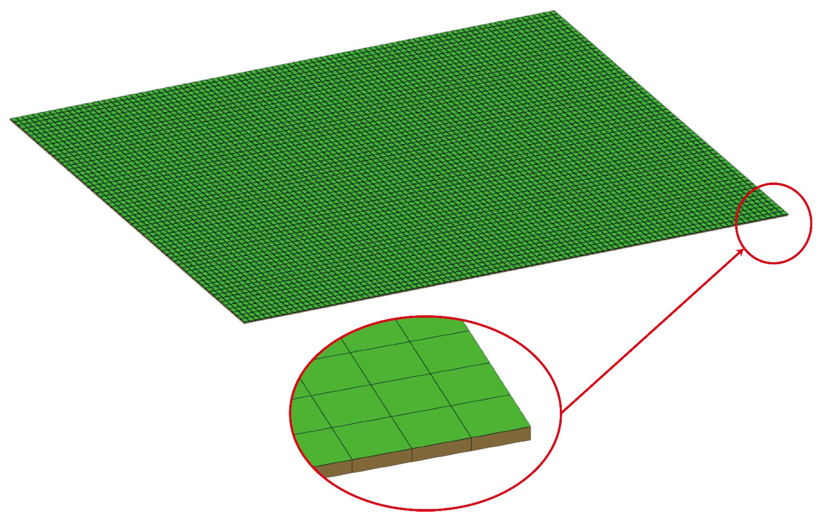
2.2. Finite Element Model

In engineering design, the commonly used vibration damping methods are active damping, semi-active damping, and passive damping. The active vibration damping is in the structure of the amplitude of the larger external damping shock absorber, the application of force and the structure of the vibration energy offsetting each other to reduce vibration, while passive damping technology only needs to lay the viscoelastic damping material on the surface of the structure, making it a highly efficient and reliable vibration damping method that is widely used in engineering practice. The basic forms of damping structures are free-layer damping and constrained-layer damping [1], as shown in Figure 1.
The characteristic of the free-layer damping structure lies in the direct application of damping material onto the surface of the steel plate. Compared to the constrained-layer damping structure, free-layer damping facilitates finite element modeling and analysis, simplifying the process of design optimization.
The steel plate is set as an offset shell element, and the damping material is represented as a hexahedral solid element. The model parameters are shown in Table 1.
The parameters of the steel plate and damping material are shown in Table 2.
The boundary conditions are the key factors affecting the dynamic behavior of the structure. In order to accurately obtain the intrinsic properties of the steel plate and damped composite structures, free boundary conditions are used for modal analysis. Free boundary conditions can accurately reflect the intrinsic modal characteristics of the structure, whereas fixed or elastic support boundaries can introduce additional stiffness and lead to modal frequency shifts. In this paper, the free boundary setting ensures that the optimization results reflect only the effect of the damping material layout on the damping performance.

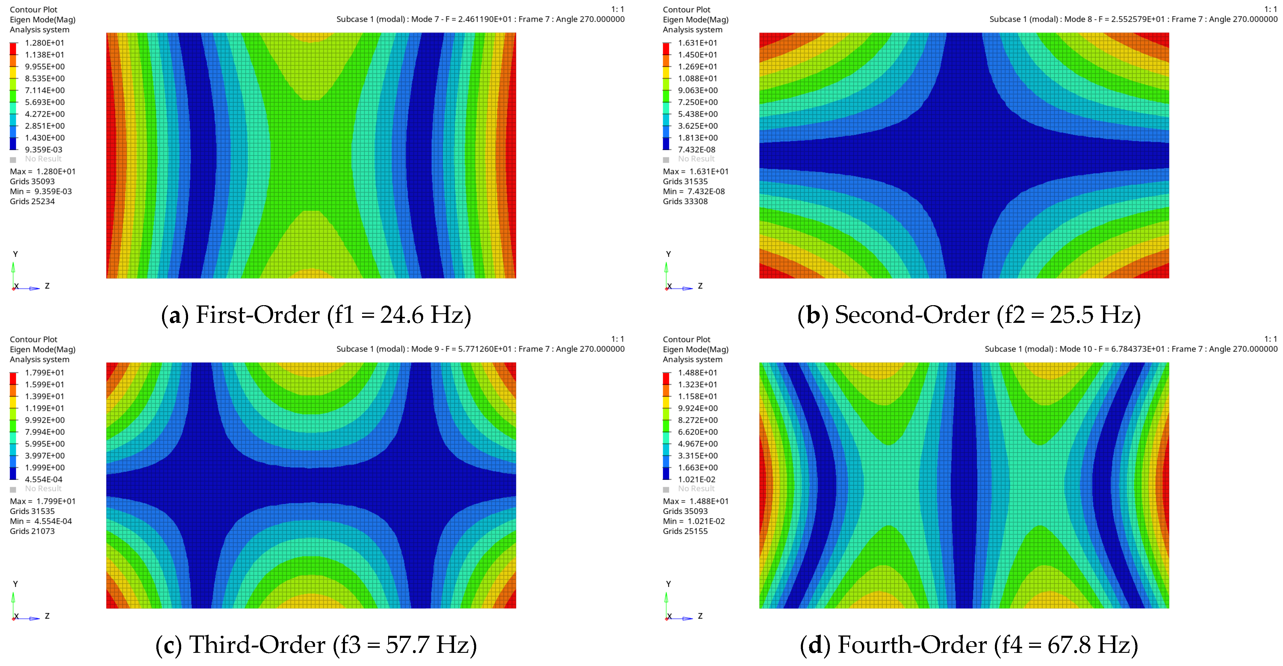
2.3. Modal Frequency Response Analysis

A modal-based frequency response analysis was conducted on the composite structure of a steel plate and damping material using HyperMesh 2020 (Altair, Troy, MI, USA) version software. The 3D mesh assigned with damping material properties was overlaid on the 2D mesh assigned with steel plate material properties, as illustrated in Figure 2.
Both elements were connected through shared nodes at the interface. This modeling approach assumes that the interface between the damping layer and the steel plate is perfectly bonded, i.e., the displacement at the interface is continuous with no relative slip or debonding.
The vibration of a structure under external excitation is the result of the superposition of various modal shapes, with the primary contribution to the vibration coming from its lower-order global modes. Therefore, when conducting modal analysis, special attention should be given to the lower-order global modes [17,18]. To analyze the modal characteristics of the structure and define the method for modal frequency response analysis, based on the mesh model of the composite structure of steel plate and damping material, a free-modal analysis method was adopted. The modal shapes are shown in Figure 3.
From Figure 3, the first four elastic modal frequencies of the steel plate and damping structure are 24.6 Hz, 25.5 Hz, 57.7 Hz, and 67.8 Hz, respectively. Considering that the low-order modes dominate the structural vibration response, but the actual engineering excitation often covers a wide frequency range, this study increases the frequency analysis range by one order of magnitude, i.e., the frequency analysis is set to 0–700 Hz.

3. Topology Optimization Method Based on Variable Density

This paper adopts a Variable Density Topology Optimization Method, dividing different structures into design areas or non-design areas to ensure that the optimized areas do not interfere with other structures [19]. In the design areas, an objective function is established based on the mechanical properties of the materials, subject to certain constraints. The objective of this function is to optimize certain performance indicators of the structure while satisfying the constraints, ultimately solving the objective function to find the optimal distribution of materials. This method can effectively optimize the structure and reduce its overall weight [20,21,22].

3.1. Design of Topology Optimization Model

The three essential elements of topology optimization are design variables, objective functions, and constraints [23]. Under harmonic excitation, the density of each finite element mesh unit of the damping material is taken as the design variable, with minimizing the harmonic response as the objective function and the volume of damping material as the constraint. The mathematical optimization model based on SIMP (Solid Isotropic Material with Penalization) is as follows [5,6]:
find :     X = x 1 , , x i , , x n T , x i 0 , 1
min :     C r = i = 1 r ϑ i x ( ω f ) ,   i = 1 r ϑ i = 1
subject   to :     V ( X ) = γ V 0 = i = 1 n s i h i x i q ( K ω i 2 M ) u i = 0 ω ¯ i l o w ω ¯ i ω ¯ i u p p e r , ω ¯ i = ω i f ω i a x min x i x max , i = 1 , 2 , , n
where X represents the optimization design variable vector, C r denotes the frequency response amplitude, ϑ i stands for the modal weights, r is the specified number of optimization modes, γ represents the optimized constraint volume ratio, and s i and h i are the unit thickness and area, respectively, for the discretized elements. The calculation formula s i h i represents the total volume of the discretized mesh elements. q is the penalty factor, x ( ω f ) is the frequency response displacement, and ω i f and ω i a are the modal frequencies of the i-th order before and after optimization, respectively. ω ¯ i u p p e r and ω ¯ i l o w are the lower and upper bounds of the normalized i-th order modal frequency. x min and x max are the minimum and maximum values for the optimization design, with values set to 0.001 and 1, respectively.

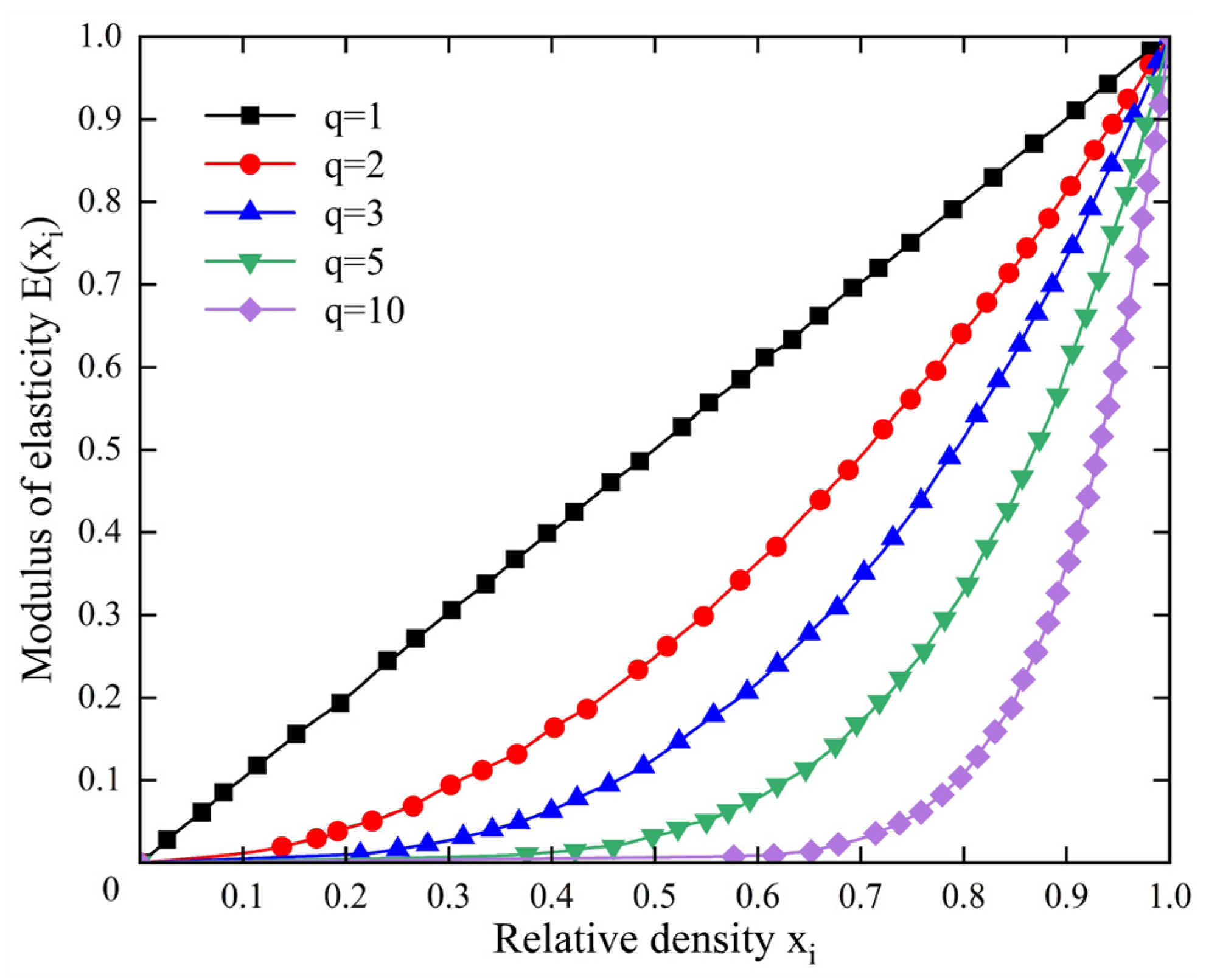
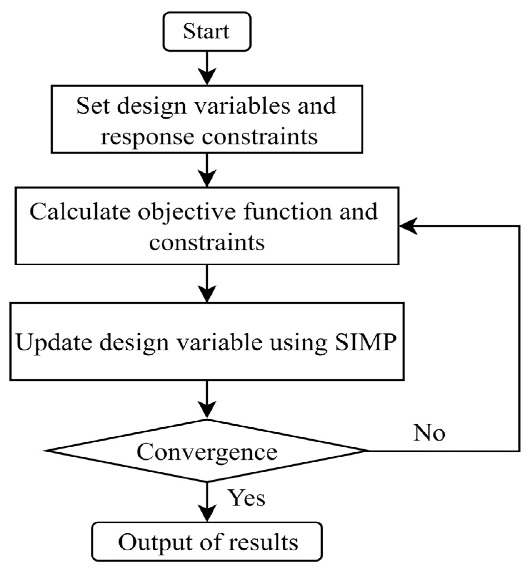
3.2. Variable Density Method

The variable density method uses the relative density of an element as the design variable. It represents the presence of material in the element (typically denoted as 1 or a high value) and the absence of material (typically denoted as 0 or a low value). Structural topology changes are achieved based on the presence or absence of elements, and the optimization goal is achieved by determining the existence of each element [24,25,26].
Using this method, a large number of intermediate density elements may exist during the optimization process. Therefore, a penalty factor is used to penalize the intermediate density values of the design variables within the range (0,1). The penalty expression is as follows [27]:
E ( x i ) = E min + x i q ( E 0 E min ) ρ ( x i ) = ρ min + x i q ( ρ 0 ρ min )
where E 0 and ρ 0 represent the initial elastic modulus and initial density of the material before optimization, respectively, while E ( x i ) and ρ ( x i ) represent the elastic modulus and density after optimization. E min and ρ min are typically set to 0.001 to avoid causing the calculation matrix to become singular. Equation (9) is known as the Solid Isotropic Material with Penalization (SIMP) density interpolation model. The SIMP method effectively approximates a continuous density-variable optimization problem as a discrete 0/1 topology optimization problem through a mathematical penalty mechanism. The relationship between the penalty parameter and the function value is illustrated in Figure 4.
From Figure 4, it can be observed that as the penalty factor q increases, the penalty effect on intermediate density values becomes stronger [28]. The value of the penalty factor q directly affects the physical reasonableness and numerical stability of the optimization results. According to the extensive research in the field of topology optimization, q = 3 is proved to be effective in suppressing the intermediate density cells while avoiding the convergence problem caused by matrix singularities [29].
The topology optimization process based on the variable density method can be represented by Figure 5.
During the topology optimization solution process in OptiStruct, the objective function converges after 30 iterations. The damping density contour plot of the optimization process is shown in Figure 6.
From the topology optimization density contour plot above, it can be observed that the structure after the 30th iteration is optimal, with a relatively continuous material distribution. Therefore, it can be selected as the basis for the optimal design of the damping material structure. The red areas in the plot indicate the parts that should be retained in the damping material structure, while the green areas represent the parts where material can be reduced during the optimization design.

4. Experimental Analysis

4.1. Experimental Equipment

The purpose of this experiment is to explore the relationship between damping and vibration frequency. Through experimentation, we can gain a better understanding of the impact of damping phenomena on vibration systems, providing a reference for the application of damping vibrations in engineering. The main equipment and instruments required for this experiment are listed in Table 3.
As the core equipment for vibration testing, the KDJ-2 exciter (Yangzhou Fangrui Electronic Technology Co., Ltd., Yangzhou, China) is responsible for generating the required vibration signals. This exciter can produce vibrations of specific frequencies, amplitudes, and waveforms (such as sine, random, shock, etc.) to simulate various vibration environments that equipment may encounter during actual operation or transportation.
The IEPE piezoelectric acceleration sensor (Guangdong Institute of Metrology, Guangzhou, China) has high sensitivity and precise measurement results, making it ideal for picking up the vibration response signals generated by the tested object after being excited.
The INV3062 signal acquisition and analysis instrument (Beijing Oriental Institute of Vibration and Noise Technology, Beijing, China) is an important data processing unit in vibration testing, responsible for receiving and recording the response signals picked up by the acceleration sensors.
The three types of equipment listed in Table 3 together constitute the basic hardware platform for vibration testing. The exciter generates the vibration input, the acceleration sensors monitor and convert the response signals, and the signal acquisition and analysis instrument is responsible for data acquisition, processing, analysis, and recording to ensure the smooth progress of the entire vibration testing experiment.

4.2. Test Setup Construction

The test object of this experiment was a steel plate with dimensions of 1000 mm × 600 mm × 5 mm, a density of 7800 kg/m3, an elastic modulus of 200 GPa, and a Poisson ratio of 0.3. The steel plate was freely suspended using elastic ropes to simulate a free state, and the suspended steel plate was interconnected with the test measurement equipment, as shown in Figure 7.
As shown in Figure 7, during the vibration test of the steel plate, an exciter with an excitation force of 1 N was used. The exciter operated in sine sweep excitation mode, with a sweep frequency range set from 0 to 700 Hz. Acceleration sensors were installed in close contact with the surface of the steel plate to capture the vibration signals of each response point under the sine sweep excitation applied by the exciter in real-time. These signals were then converted into electrical signals and output to the signal acquisition and analysis instrument. The signal acquisition and analysis instrument was connected to a computer through a dedicated interface, and the vibration analysis software running on the computer could receive and analyze a large amount of vibration data transmitted from the signal source in real time.
The specific locations of the response points on the steel plate are shown in Figure 8. A total of 15 key response points were set on the steel plate, arranged in a planned and uniform distribution pattern on the surface. This arrangement allowed for a detailed analysis of its dynamic mechanical behavior, ensuring that the test data comprehensively and effectively reflected the overall vibration behavior of the steel plate.

4.3. Test Results and Analysis

Vibration signals of steel plates usually contain multiple frequency components. The root mean square (RMS) value of the vibration acceleration at the 15 response points on the steel plate was selected to represent the overall frequency response characteristics of the steel plate. The RMS value can characterize the vibration amplitude of the steel plate at a specific excitation frequency, and its calculation formula is as follows [30]:
R M S = i = 1 n x i 2 n = x 1 2 + x 2 2 + x 3 2 + + x n 2 n
where R M S ‘’ x i represents the vibration acceleration at each response point on the steel plate, and n represents the number of response points. By substituting the vibration amplitude of each response point on the steel plate and the number of response points into Equation (10), the frequency response function of the steel plate under excitation can be calculated and analyzed.
In the steel plate test, three conditions were considered: an undamped steel plate, fully damped steel plate, and optimized damped steel plate. The frequency response function values calculated for each condition are shown in Table 4.
Physical images of the three test conditions for the steel plate are shown in Figure 9.
Figure 9 corresponds to the tests of the undamped steel plate, fully damped steel plate, and optimized damped steel plate, respectively. In the optimized damped steel plate test, the damping material was cut according to the simulation optimization scheme, as shown in Figure 9c. The optimized damping structure accounts for 68.8% of the volume of the fully covered damping structure.
Vibration signals were collected at 15 specific response points, and corresponding frequency response values were obtained through calculation and processing. These values were then compared with the frequency response values obtained from simulation analysis, as shown in Figure 10.
As shown in Figure 10, the overall trend of the experimental and simulation results for the steel plate structure shows good agreement, particularly in the low-frequency region, indicating that the model can predict the system’s response to frequency input signals well. Although there may be slight deviations in the positions of some peaks and troughs, the peak and trough positions of the experimental and simulated curves are relatively consistent overall, suggesting that the model can effectively capture the key dynamic characteristics of the system.
Despite some local differences, the overall agreement between the experimental and simulation data is high, indicating that the simulation method used can largely reflect the real situation. However, further research may be needed to determine the causes of those peaks that deviate significantly, such as whether they are due to experimental errors, inaccurate parameter settings, or unconsidered factors.
The response amplitude of the optimized design is slightly higher than that of the full-coverage scheme, which is the result of the inevitable trade-off between the pursuit of the overall band-optimal vibration damping effect under the strict volume constraints and the significant lightweighting, indicating that the optimized condition with a 31.2% reduction in damping material obtained a significant suppression effect. This fully confirms the effectiveness of the optimization method and the optimization program. With minimal impact on the performance of the damping material attached to the steel plate, the actual volume of damping material can be reduced as much as possible to achieve the goals of reducing engineering costs and improving structural lightweighting.

5. Conclusions

This study conducted an optimized design for the reduction of vibrations in a composite structure of a steel plate and damping material using a variable density topology optimization algorithm. By combining finite element simulation and experimental validation, this paper demonstrated good consistency between simulation and experimental data, verifying the effectiveness of the optimized design. The optimized design maintained excellent vibration reduction performance while reducing the amount of damping material used, proving the validity of this method.
(A)
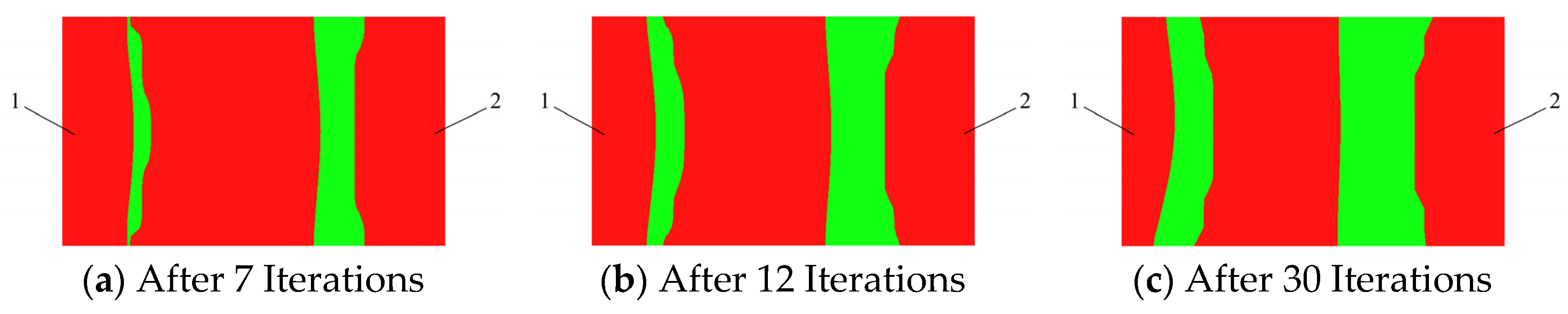
The SIMP (Solid Isotropic Material with Penalization) variable density topology optimization algorithm adopted in this paper was able to finely regulate the microstructure of materials to achieve optimal material layout design for superior damping performance.
(B)
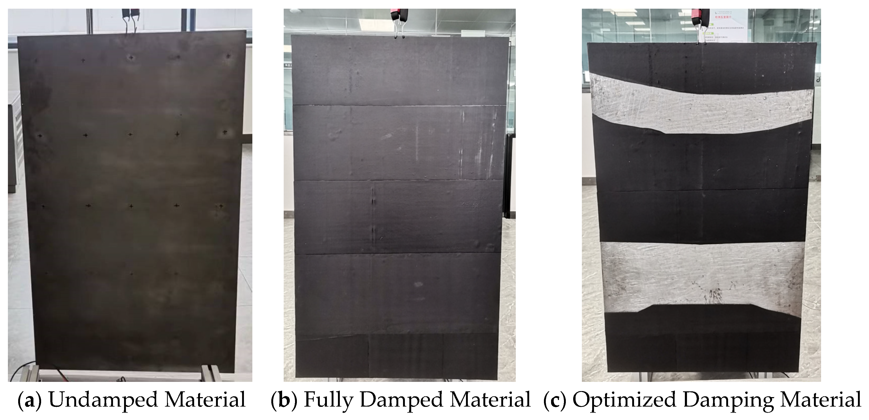
By combining finite element simulation and experimental validation, this paper not only conducted theoretical design optimization but also verified the effectiveness of the design through experiments, ensuring the validity and correctness of simulated and practical effects. The optimized design reduced the amount of damping material used by 31.2%, with an equal percentage of reduction in structural mass and material costs, while achieving a significant reduction in vibration response, which has important practical significance in engineering applications, especially in terms of cost control and structural lightweighting.
(C)
This method can be widely applied in fields such as automobiles, aerospace, and civil engineering, and has important practical significance for achieving structural lightweighting and cost optimization. The application of optimization algorithms can significantly improve design efficiency, reduce the number of design iterations, and shorten the design cycle. By reducing the amount of damping material used, engineering costs can be effectively lowered, economic benefits can be improved, and resource consumption and environmental pollution can be reduced, aligning with sustainable development requirements.
Despite the significant achievements of this study, there are still some limitations. Firstly, the optimized design is only specific to the composite structure of a steel plate and damping material, and further research may be needed for other types of structures. Secondly, the experimental conditions were relatively idealized, and more complex situations may be encountered in practical engineering applications. Future research will further extend to the study of the sound insulation performance of damping plates, optimizing the structure of damping layers through optimization methods to form damping acoustic cavity structures and exploring their sound absorption and insulation effects at different frequencies to achieve optimal sound insulation performance across a wide frequency range.

Author Contributions

The presented work was conducted under the supervision of X.Z. and H.L.: conceptualization, methodology, software and writing—review; B.H. and C.D.: conceptualization, methodology, software, and writing—original draft; Z.K., and K.W.: validation and writing—review and editing; W.W. and H.D.: methodology and writing—review. J.W.: writing and translation. All authors have read and agreed to the published version of the manuscript.

Funding

This research received no external funding.

Data Availability Statement

The dataset is available upon request from the authors.

Acknowledgments

The authors acknowledge the editors and reviewers for their constructive comments and all the supports on this work.

Conflicts of Interest

Author Jiangang Wang was employed by Guangdong LIK Industry Co., Ltd. The remaining authors declare that the research was conducted in the absence of any commercial or financial relationships that could be construed as a potential conflict of interest.

References

  1. Wang, F.; Liao, J.; Huang, C.; Yu, H.; Yan, J.; Li, H. Study on the Damping Dynamics Characteristics of a Viscoelastic Damping Material. Processes 2022, 10, 635. [Google Scholar] [CrossRef]
  2. Zhao, X.; Wu, B.; Lai, S.-K.; Liu, W.; Zhong, H. Topology optimization of proportionally damped structures under harmonic excitations: Analysis of velocity and acceleration responses. Eng. Struct. 2022, 258, 114140. [Google Scholar] [CrossRef]
  3. Bai, C.; Chen, T.; Wang, X.; Sun, X. Optimization layout of damping material using vibration energy-based finite element analysis method. J. Sound Vib. 2021, 504, 116117. [Google Scholar] [CrossRef]
  4. Chen, B.; Dai, J.; Song, T.; Guan, Q. Research and Development of High-Performance High-Damping Rubber Materials for High-Damping Rubber Isolation Bearings: A Review. Polymers 2022, 14, 2427. [Google Scholar] [CrossRef] [PubMed]
  5. Zhang, H.; Ding, X.; Wang, Q.; Ni, W.; Li, H. Topology optimization of composite material with high broadband damping. Comput. Struct. 2020, 239, 106331. [Google Scholar] [CrossRef]
  6. Zhao, X.; Wu, B.; Li, Z.; Zhong, H. A method for topology optimization of structures under harmonic excitations. Struct. Multidiscip. Optim. 2018, 58, 475–487. [Google Scholar] [CrossRef]
  7. El-Sabbagh, A.; Baz, A. Topology optimization of unconstrained damping treatments for plates. Eng. Optim. 2013, 46, 1153–1168. [Google Scholar] [CrossRef]
  8. Allaire, G.; Michailidis, G. Modal basis approaches in shape and topology optimization of frequency response problems. Int. J. Numer. Methods Eng. 2018, 113, 1258–1299. [Google Scholar] [CrossRef]
  9. Wan, C.; Jiao, H.; Lv, L.; Lu, C. Multi-material topology optimization based on multiple simp of variable density method. J. Mech. Sci. Technol. 2024, 38, 749–759. [Google Scholar] [CrossRef]
  10. Xie, L.; Zhang, Y.; Ge, M.; Zhao, Y. Topology optimization of heat sink based on variable density method. Energy Rep. 2022, 8, 718–726. [Google Scholar] [CrossRef]
  11. Höke, Ö.; Bozca, M. Topology Optimisation of Engine Cross Members for Lightweight Structure in Light Commercial Vehicles. Int. J. Precis. Eng. Manuf. 2020, 21, 465–482. [Google Scholar] [CrossRef]
  12. Steffensen, M.T.; Tcherniak, D.; Thomsen, J.J. Accurate frequency response function estimation using noise measurements in experimental modal analysis. J. Phys. Conf. Ser. 2024, 2647, 212003. [Google Scholar] [CrossRef]
  13. Mudahemuka, E.; Miyagi, M.; Shin, R.; Kaneko, N.; Okada, Y.; Yamamoto, K. Estimating Bridge Natural Frequencies Based on Modal Analysis of Vehicle–Bridge Synchronized Vibration Data. Sensors 2024, 24, 1060. [Google Scholar] [CrossRef] [PubMed]
  14. Sestieri, A.; D’Ambrogio, W. Frequency response function versus output-only modal testing identification. In Proceedings of the 21st International Modal Analysis Conference (IMAC XXI), Kissimmee, FL, USA, 3–6 February 2003; pp. 41–46. [Google Scholar]
  15. De Carolis, S.; Messina, A.; Soria, L. Modal analysis through response-based FRFs: Additional modes for local diagnoses. J. Sound Vib. 2023, 549, 117574. [Google Scholar] [CrossRef]
  16. Abdullah, N.; Fouzi, M.; Sani, M.M. Computational Modal Analysis on Finite Element Model of Body-in-white Structure and Its Correlation with Experimental Data. Int. J. Automot. Mech. Eng. 2020, 17, 7915–7926. [Google Scholar] [CrossRef]
  17. Katsurayama, Y.; Deng, M.; Jiang, C. Operator-based experimental studies on nonlinear vibration control for an aircraft vertical tail with considering low-order modes. Trans. Inst. Meas. Control 2016, 38, 1421–1433. [Google Scholar] [CrossRef]
  18. Brincker, R.; Skafte, A.; López-Aenlle, M.; Sestieri, A.; D’Ambrogio, W.; Canteli, A. A local correspondence principle for mode shapes in structural dynamics. Mech. Syst. Signal Process. 2014, 45, 91–104. [Google Scholar] [CrossRef]
  19. Wu, J.; Sigmund, O.; Groen, J.P. Topology optimization of multi-scale structures: A review. Struct. Multidiscip. Optim. 2021, 63, 1455–1480. [Google Scholar] [CrossRef]
  20. Zhang, Z.; Zhao, Y.; Du, B.; Chen, X.; Yao, W. Topology optimization of hyperelastic structures using a modified evolutionary topology optimization method. Struct. Multidiscip. Optim. 2020, 62, 3071–3088. [Google Scholar] [CrossRef]
  21. Yamamoto, T.; Yamada, T.; Izui, K.; Nishiwaki, S. Topology optimization of free-layer damping material on a thin panel for maximizing modal loss factors expressed by only real eigenvalues. J. Sound Vib. 2015, 358, 84–96. [Google Scholar] [CrossRef]
  22. Ma, L.; Cheng, L. Topological optimization of damping layout for minimized sound radiation of an acoustic black hole plate. J. Sound Vib. 2019, 458, 349–364. [Google Scholar] [CrossRef]
  23. Costa, G.; Montemurro, M. Eigen-frequencies and harmonic responses in topology optimisation: A CAD-compatible algorithm. Eng. Struct. 2020, 214, 110602. [Google Scholar] [CrossRef]
  24. Zuo, W.; Saitou, K. Multi-material topology optimization using ordered SIMP interpolation. Struct. Multidiscip. Optim. 2017, 55, 477–491. [Google Scholar] [CrossRef]
  25. Zargham, S.; Ward, T.A.; Ramli, R.; Badruddin, I.A. Topology optimization: A review for structural designs under vibration problems. Struct. Multidiscip. Optim. 2016, 53, 1157–1177. [Google Scholar] [CrossRef]
  26. Martinez, J.M. A note on the theoretical convergence properties of the SIMP method. Struct. Multidiscip. Optim. 2005, 29, 319–323. [Google Scholar] [CrossRef]
  27. Zhang, S.; Li, H.; Huang, Y. An improved multi-objective topology optimization model based on SIMP method for continuum structures including self-weight. Struct. Multidiscip. Optim. 2021, 63, 211–230. [Google Scholar] [CrossRef]
  28. Liang, J.; Zhang, X.; Zhu, B.; Wang, R.; Cui, C.; Zhang, H. Topology Optimization of Geometrically Nonlinear Structures Based on a Self-Adaptive Material Interpolation Scheme. Machines 2023, 11, 1047. [Google Scholar] [CrossRef]
  29. Lian, R.; Jing, S.; He, Z.; Shi, Z. A Hierarchical Double Penalty Method of Gray-Scale Elements for SIMP in Topology Optimization. J. Comput.-Aided Des. Comput. Graph. 2020, 32, 1349–1356. [Google Scholar]
  30. Wang, F.; Bollen, M. Frequency-Response Characteristics and Error Estimation in RMS Measurement. IEEE Trans. Power Deliv. 2004, 19, 1569–1578. [Google Scholar] [CrossRef]
Figure 1. Forms of damping structures.
Processes 13 02276 g001
Figure 2. The green section represents the steel plate structure, while the brown section represents the damping structure.
Processes 13 02276 g002
Figure 3. Modal shapes of steel plate and damping structure.
Processes 13 02276 g003
Figure 4. SIMP material interpolation model.
Processes 13 02276 g004
Figure 5. OptiStruct topology optimization flowchart.
Processes 13 02276 g005
Figure 6. Damping optimization iteration plot (red areas represent damping material): 1—suspension point; 2—excitation point.
Processes 13 02276 g006
Figure 7. Test equipment setup.
Processes 13 02276 g007
Figure 8. Distribution of response points.
Processes 13 02276 g008
Figure 9. Physical images of steel plate tests.
Processes 13 02276 g009
Figure 10. Comparison of experimental and simulated frequency responses.
Processes 13 02276 g010
Table 1. Finite element parameters.
NameDimensions
(L* W* H)/mm
Mesh Element CountMesh Size/mmMesh NodesElement Type
Steel Plate1000 × 600 × 5600010 × 106161PSHELL
Damping Plate1000 × 600 × 2.5600010 × 10 × 2.512,322PSOLID
Table 2. Material parameters.
NameElastic
Modulus/MPa
Density/(kg/m3)Poisson’s
Ratio
Thickness/mmDamping Ratio
Steel Plate200,00078000.35-
Damping Plate720000.42.50.12
Table 3. Main experimental equipment for vibration testing.
NameModelSensitivity/(mV/ms−2)
ExciterKDJ-2-
Signal Acquisition and Analysis InstrumentINV3062-
Accelerometer-1IEPE1.01
Accelerometer-2IEPE1.04
Accelerometer-3IEPE1.04
Accelerometer-4IEPE1.02
Table 4. Frequency response function values for each condition.
Frequency/HzAmplitude of Undamped Steel Plate/(mm/s2/N)Amplitude of Fully Damped Steel Plate/(mm/s2/N)Amplitude of Optimized Damped Steel Plate/(mm/s2/N)
301.41500.25840.30508
758.15210.98821.2947
14014.19661.12421.13825
2002.91791.66781.9760
28514.85170.89040.9649
3803.11060.92721.0900
41019.24162.28762.62454
54029.30700.69750.7508
6356.61440.97071.1177
68013.18890.540160.05472
Disclaimer/Publisher’s Note: The statements, opinions and data contained in all publications are solely those of the individual author(s) and contributor(s) and not of MDPI and/or the editor(s). MDPI and/or the editor(s) disclaim responsibility for any injury to people or property resulting from any ideas, methods, instructions or products referred to in the content.

