
The Influence of Secondary Air Guide Vanes on the Flow Field and Performance of a Turbine Air Classifier

Abstract
1. Introduction
2. Calculation Methodology
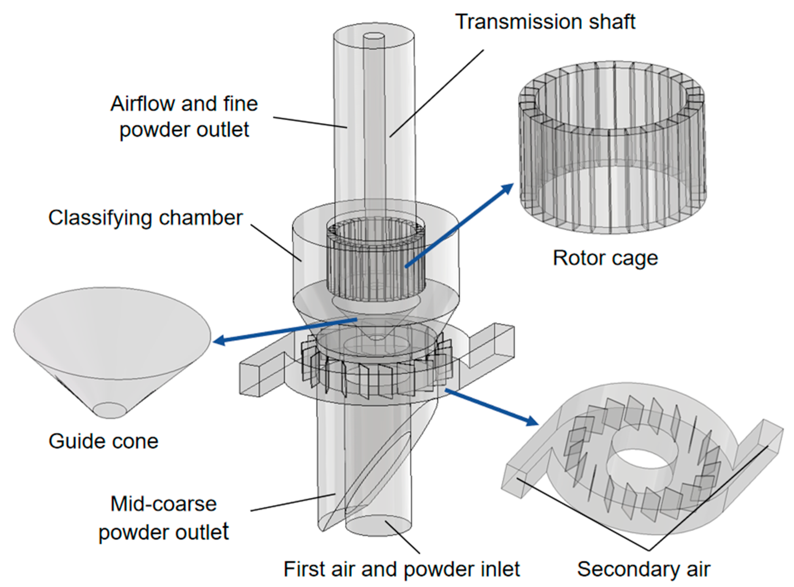
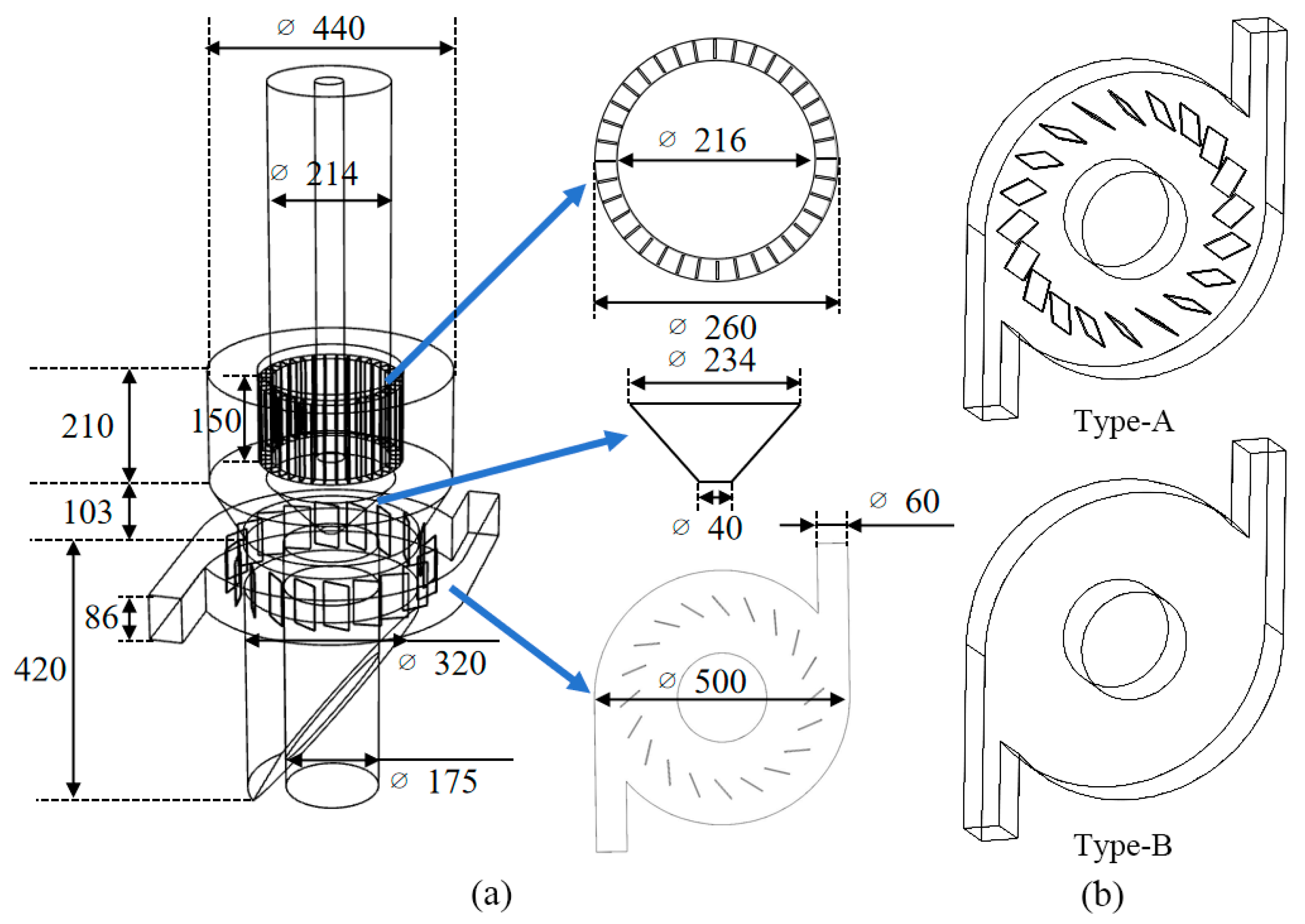
2.1. Description of the Equipment
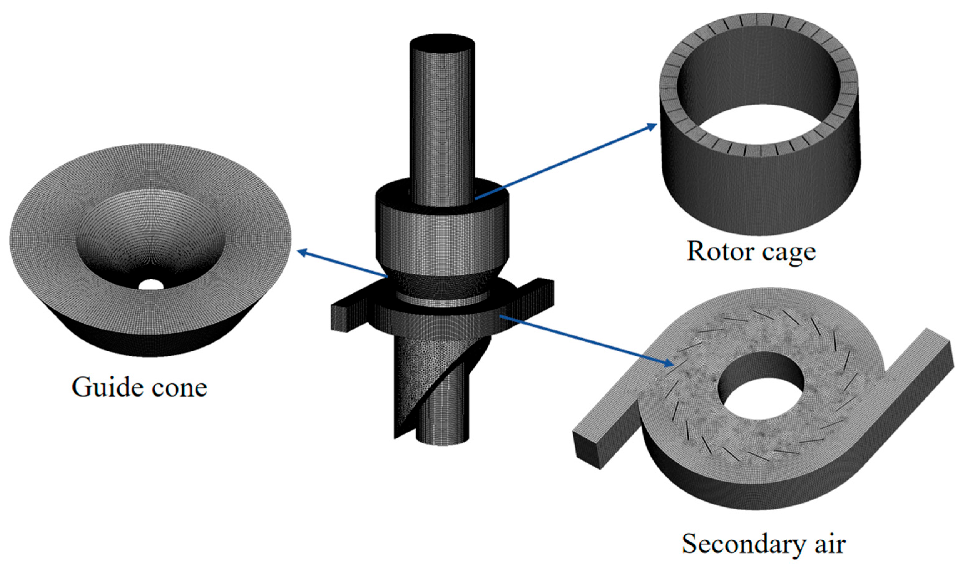
2.2. Model Establishment and Mesh Generation
2.3. Turbulence Model and Simulation Conditions
2.4. Discrete-Phase Model
2.5. Classification Performance Indexes
3. Effect of the Presence or Absence of Secondary Air Guide Vanes on the Flow Field
3.1. Overall Flow Field Distribution
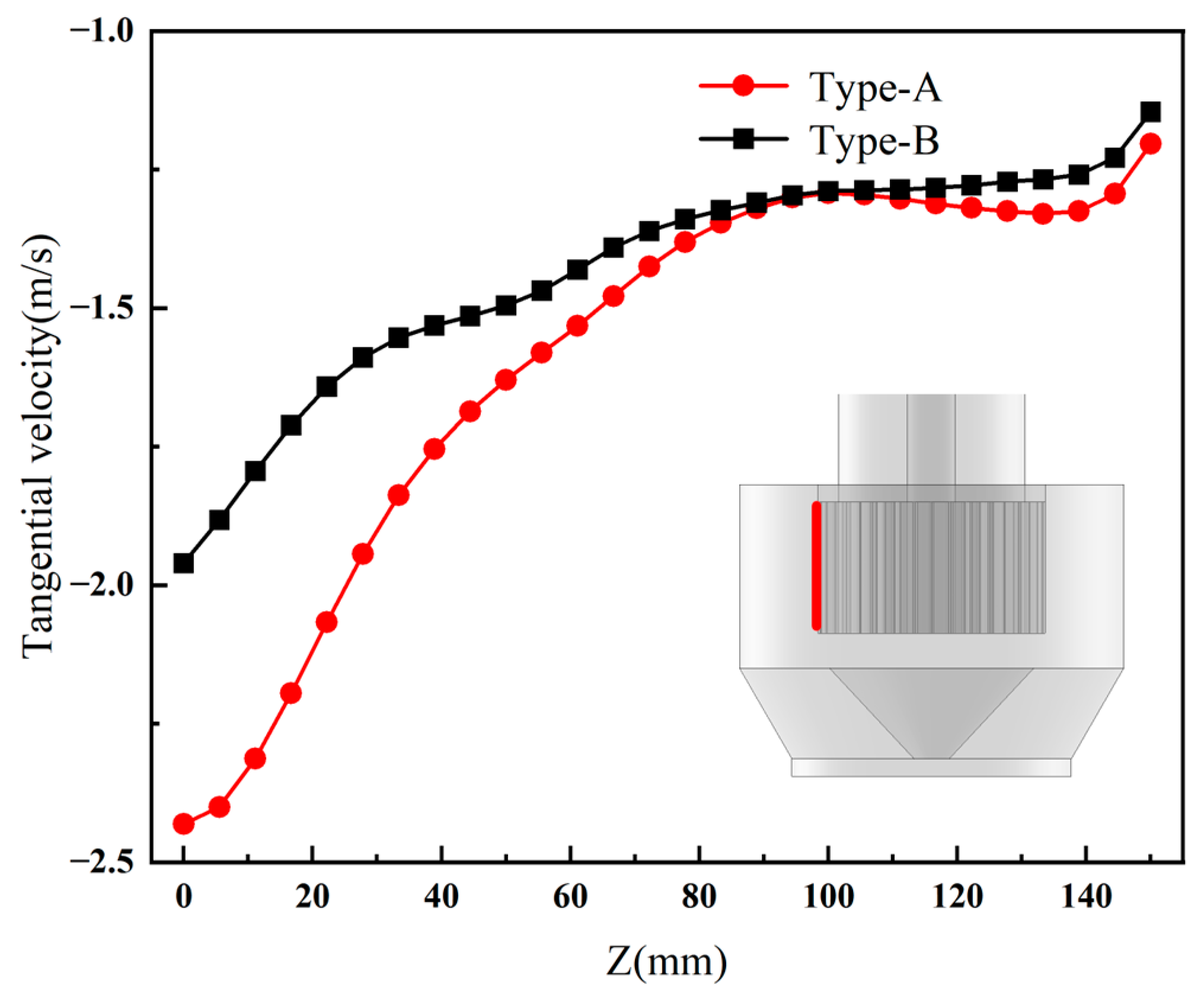
3.2. Effect of Type-A and Type-B Structures on Tangential Velocity in the Annular Zone
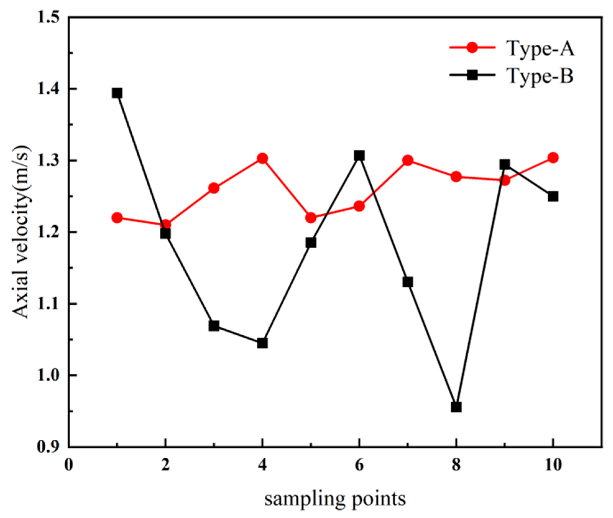
3.3. Influence of Type-A and Type-B Structures on the Flow Field in the Secondary Elution Zone
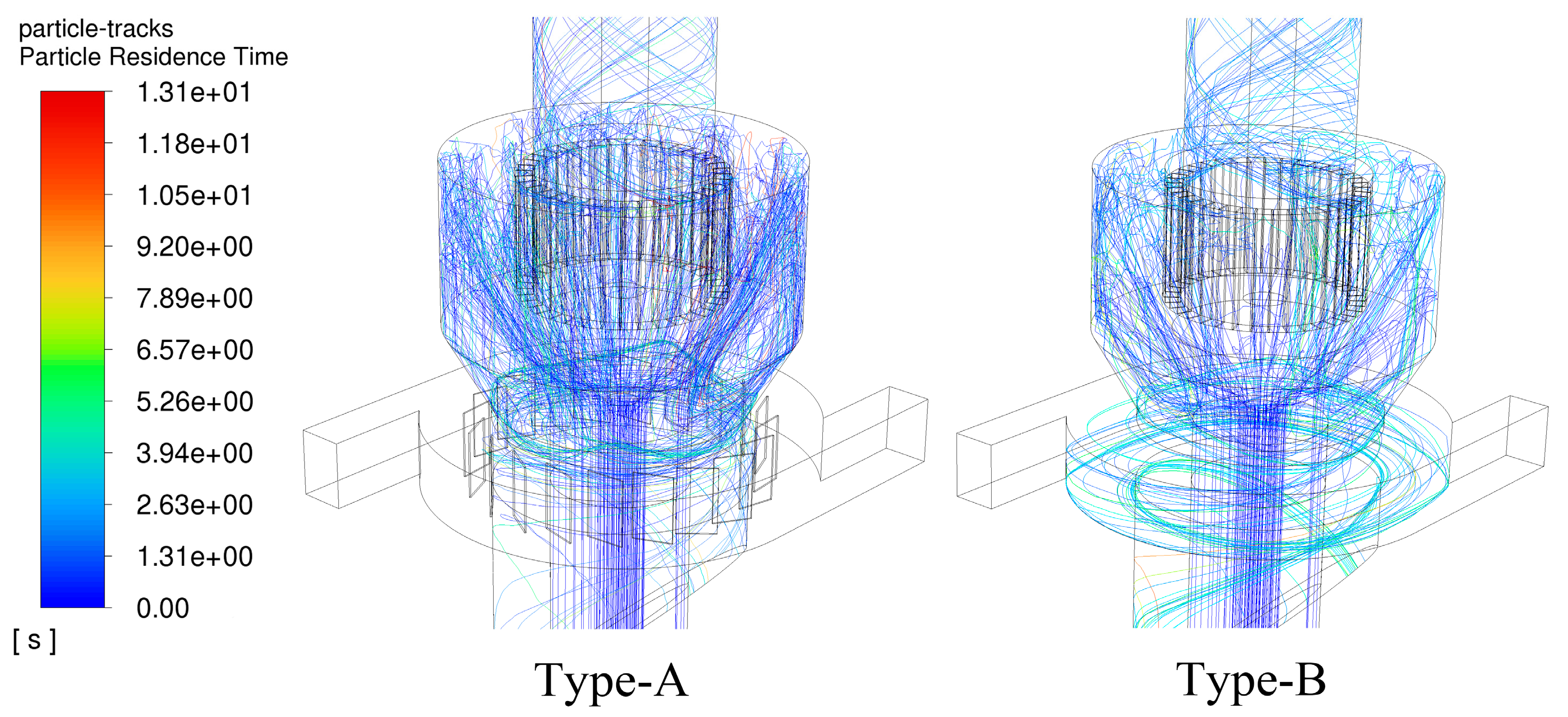
3.4. Analysis of Discrete-Phase Simulation Results
4. Influence of the Angle of the Secondary Air Guide Blade on the Flow Field
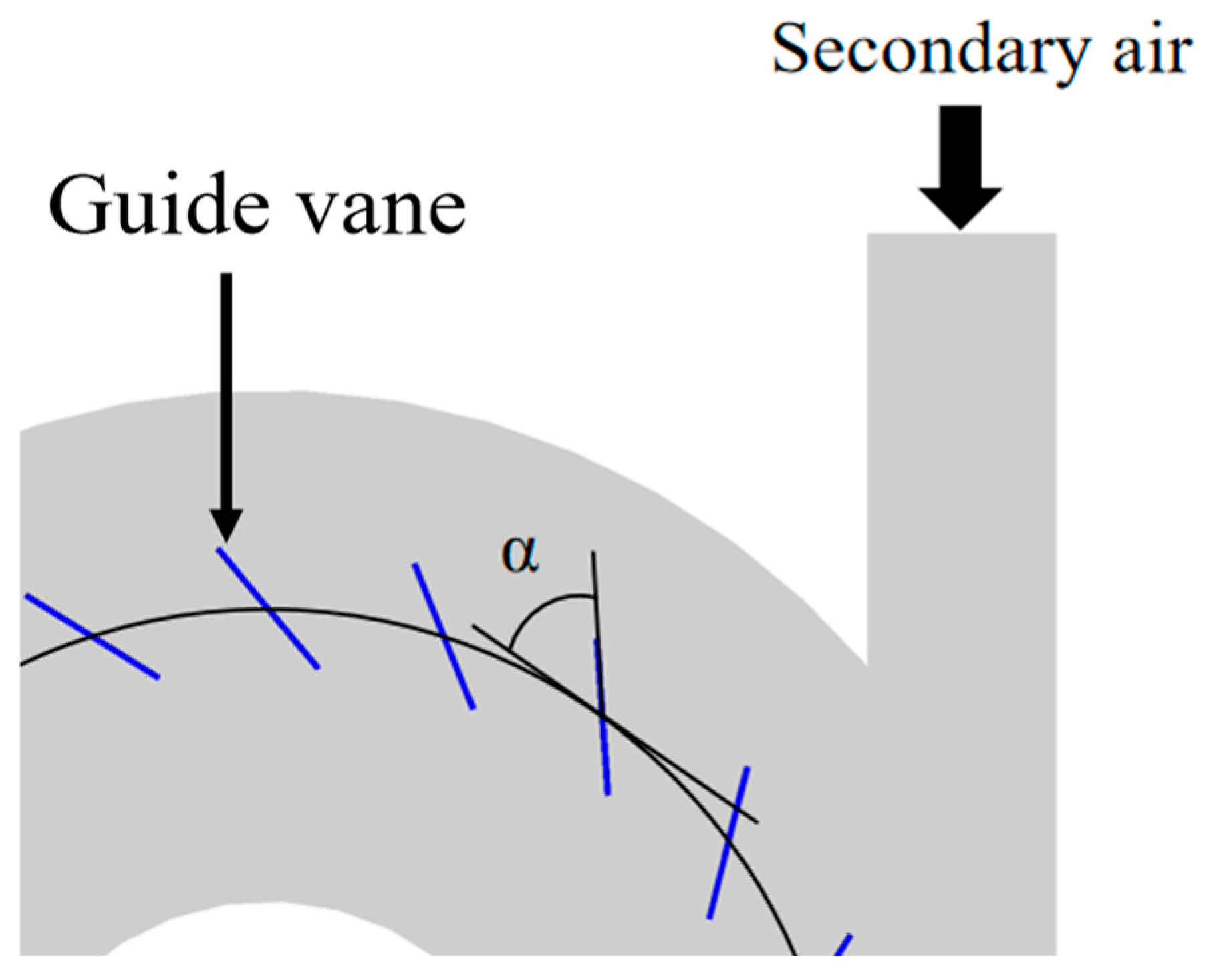
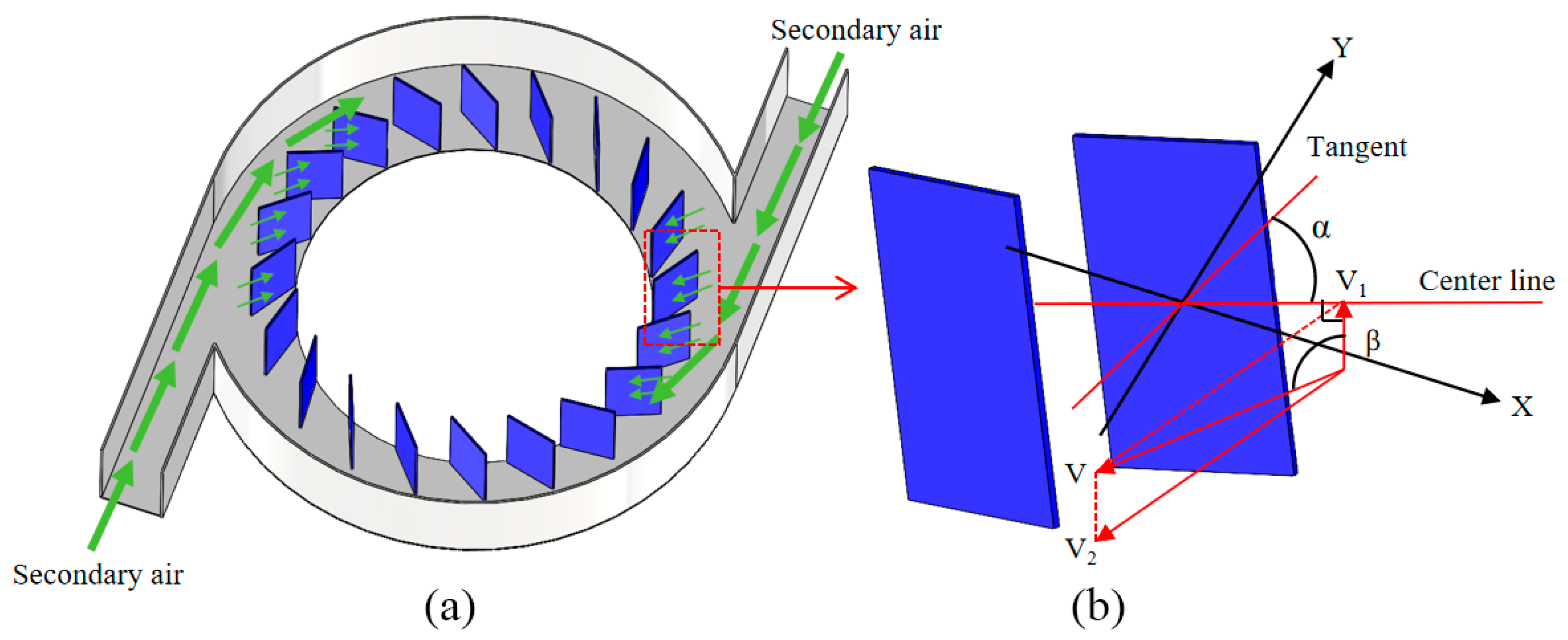
4.1. Guide Blade Setting Angle Model
4.2. Guide Vane Design and Flow Characterization
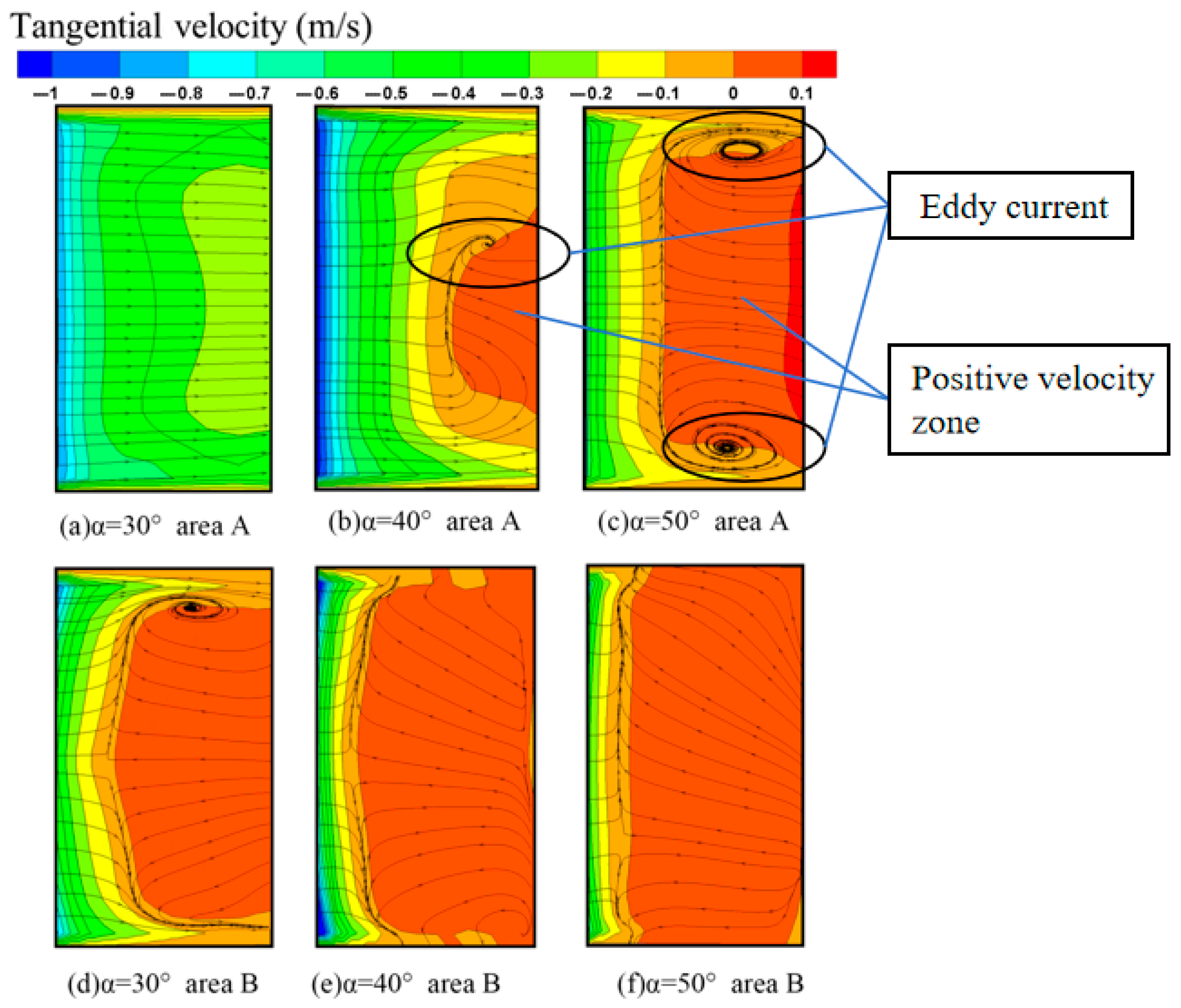
4.3. Effect of Different Angles of Guide Vanes on Tangential Velocity
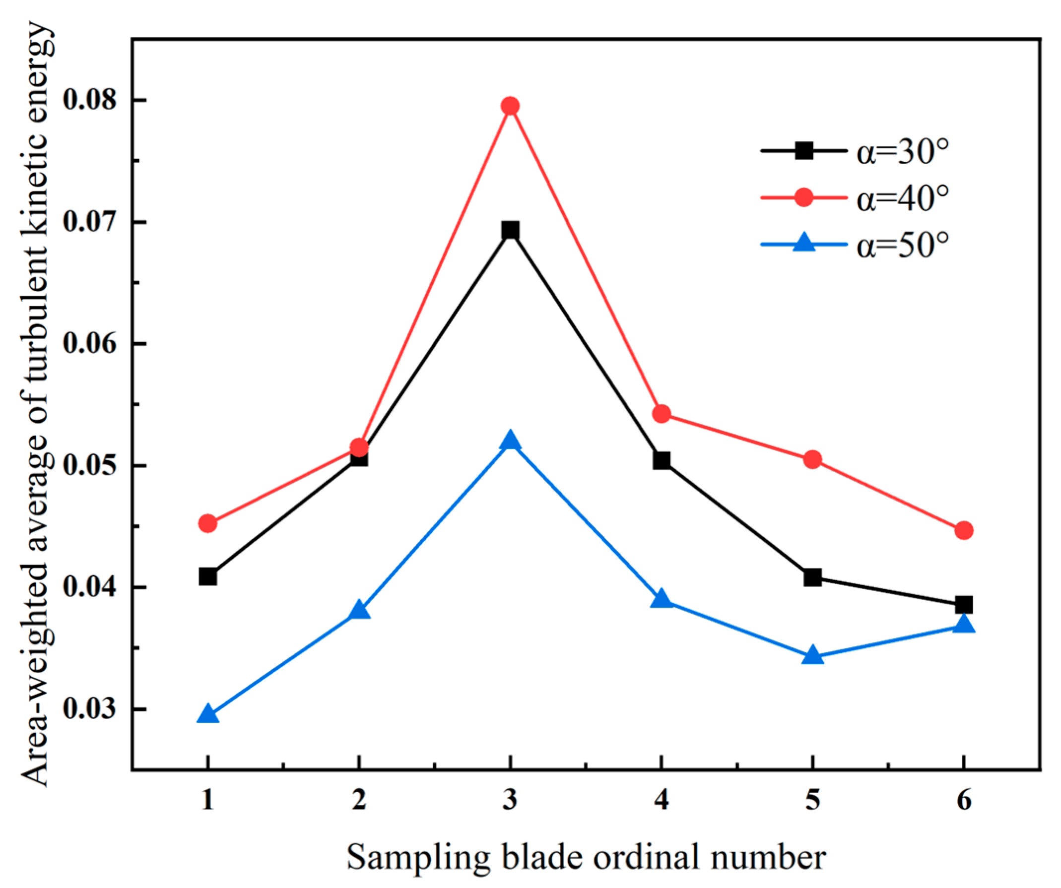
4.4. The Influence of Installation Angle on the Vorticity and Turbulent Kinetic Energy of Guide Vanes
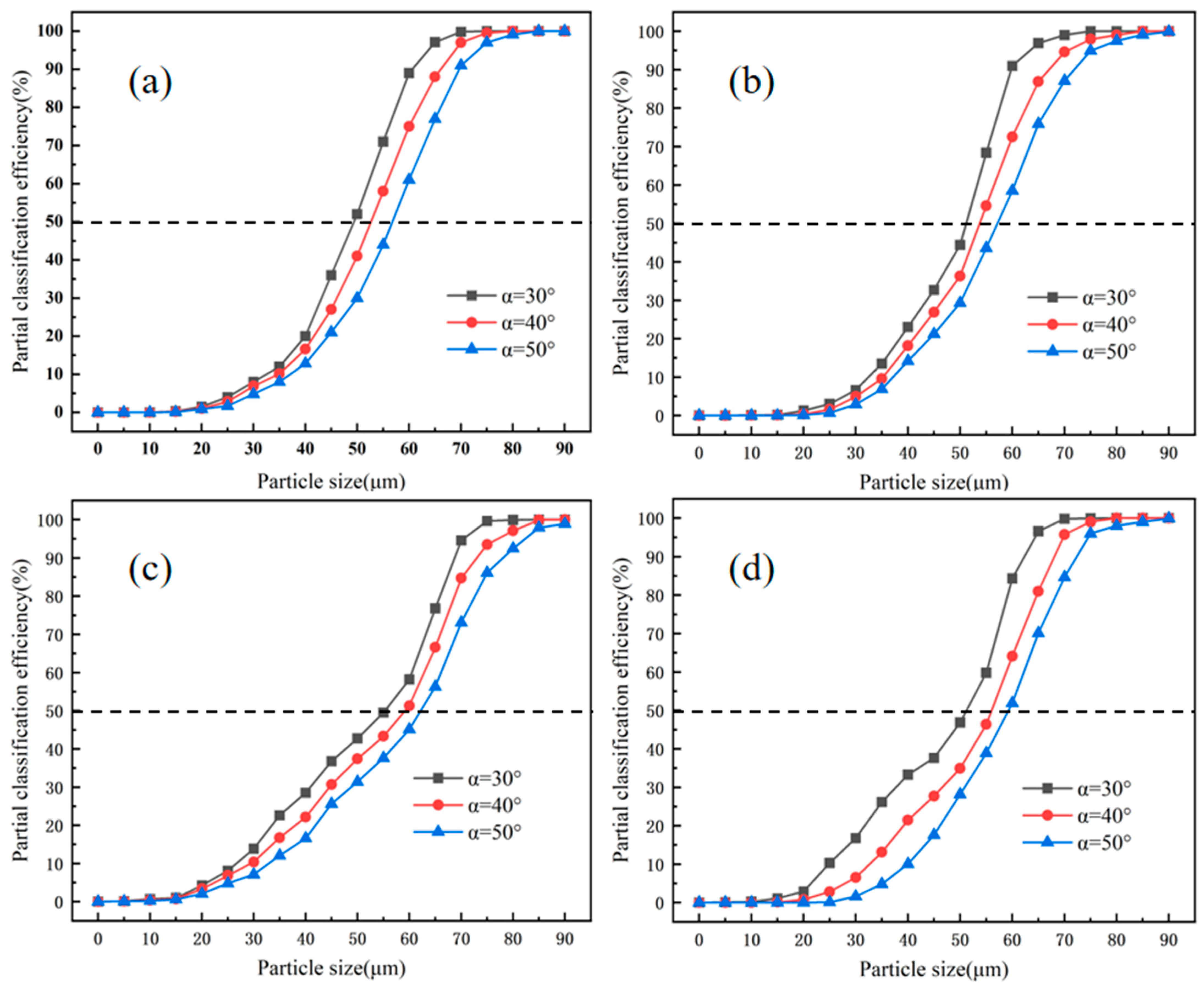
4.5. Analysis of Discrete-Phase Simulation Results
5. Experimental Results and Analysis
5.1. Experimental Setup and Material
5.2. Comparison of Simulation and Experimental Results
6. Conclusions
- Compared to the secondary air configuration without guide vanes, the configuration with guide vanes exerted a more significant influence on the tangential velocity in the classification zone, substantially enhancing it. Furthermore, this design significantly improved the axial velocity and flow field stability in the secondary elutriation zone. Additionally, the guide vane structure effectively mitigated the rise in particle concentration within the volute.
- The secondary air guide vane structure significantly enhanced the classifier’s performance, demonstrating its most pronounced improvement at an installation angle of 30°. This angle effectively promoted flow field stability, maintaining turbulent kinetic energy on the guide vane surfaces within an optimal range. Experimental studies indicated that installation angles either too large or too small adversely affected particle classification. Furthermore, DPM model simulations confirmed that classification efficiency peaked at 30°, optimizing powder separation efficiency.
- Material experiments revealed that although some discrepancies existed between simulation and experimental results, the DPM model could still accurately predict the trend of grading efficiency. This demonstrates its value for the structural optimization of the air classifier.
- This study elucidated how the angle of the guide vanes regulated the secondary air flow field and classification performance, identifying 30° as the optimal angle. Implementing this optimal angle can directly enhance the efficiency and stability of existing classifiers, while simultaneously reducing energy consumption and maintenance costs. Future research will explore curved guide vane geometries, unsteady flow simulations, and adaptability to multiple materials, and will further verify the application of this optimized design in industrial classifiers.
Author Contributions
Funding
Data Availability Statement
Conflicts of Interest
References
- Lee, S.; Jeong, S.B. Enrichment by air classification of indium components from In-containing scrap powders scraped by sand-blasting chamber shields of sputter coaters. Rare Met. 2010, 29, 1–8. [Google Scholar] [CrossRef]
- Denmud, N.; Baite, K. Effects of Operating Parameters on the Cut Size of Turbo Air Classifier for Particle Size Classification of SAC305 Lead-Free Solder Powder. Processes 2019, 7, 427. [Google Scholar] [CrossRef]
- Yu, Y.; Kong, X. Effect of rotor cage’s outer and inner radii on the inner flow field of the turbo air classifierEinfluss von Aussen- und Innenradien des Rotorkafigs auf das innere Flussfeld von einem Turbo-Luftsichter. Mater. Werkst. 2020, 51, 908–919. [Google Scholar] [CrossRef]
- Yu, Y.; Liu, J. A parametric cut size prediction model for a turbo air classifier. Mater. Werkst. 2018, 49, 1510–1519. [Google Scholar] [CrossRef]
- Zeng, Y.; Zhang, S. Numerical Simulation of a Flow Field in a Turbo Air Classifier and Optimization of the Process Parameters. Processes 2020, 8, 237. [Google Scholar] [CrossRef]
- Hui, C.X.; Li, Q. Computational fluid dynamics simulation and performance study of a three-separation combined air classifier. Therm. Sci. 2024, 28, 1589–1603. [Google Scholar] [CrossRef]
- Esmaeilpour, M.; Mohebbi, A. CFD simulation and optimization of an industrial cement gas-solid air classifier. Particuology 2024, 89, 172–184. [Google Scholar] [CrossRef]
- Kim, M.; Cha, J. Ring-Shaped Baffle Effect on Separation Performance of Lithium Carbonate Micro Particles in a Centrifugal Classifier. Micromachines 2020, 11, 980. [Google Scholar] [CrossRef] [PubMed]
- Abohelwa, M.; Benker, B. Limitation in the Performance of Fine Powder Separation in a Turbo Air Classifier. Processes 2023, 11, 2817. [Google Scholar] [CrossRef]
- Yu, Y.; Wang, L. Analysis of numerical simulation models for the turbo air classifierAnalyse eines numerischen Simulationsmodells fur einen Turbowindsichter. Mater. Werkst. 2022, 53, 644–657. [Google Scholar] [CrossRef]
- Peng, J.X.; Hui, C.X. Research and Optimization of Operating Parameters of a Rotor Classifier for Calcined Petroleum Coke. Processes 2024, 12, 603. [Google Scholar] [CrossRef]
- Yu, Y.; Ren, W. Analysis and optimization of process parameters affecting classification performances indices of the turbo air classifier. Mater. Werkst. 2015, 46, 970–977. [Google Scholar] [CrossRef]
- Mou, X.L.; Jia, F.C. CFD-Based Structural Optimization of Rotor Cage for High-Efficiency Rotor Classifier. Processes 2021, 9, 1148. [Google Scholar] [CrossRef]
- Jia, F.C.; Mou, X.L. A New Rotor-Type Dynamic Classifier: Structural Optimization and Industrial Applications. Processes 2021, 9, 1033. [Google Scholar] [CrossRef]
- Li, Q.; Mou, X.L. Effects of a Guide Cone on the Flow Field and Performance of a New Dynamic Air Classifier. Processes 2022, 10, 874. [Google Scholar] [CrossRef]
- Yang, H.D.; Sun, Z.P. Vortex analysis and flow field optimization for the particle classifier with three rotary cages. Adv. Powder Technol. 2023, 34, 12. [Google Scholar] [CrossRef]
- Yu, Y.; Chen, W. Design of the new guide vane for the turbo air classifierDesign eines neuen Austrittsleitrads fur Turbo-Luftsichter. Mater. Werkst. 2023, 54, 196–206. [Google Scholar] [CrossRef]
- Liu, R.R.; Liu, J.X. Effects of axial inclined guide vanes on a turbo air classifier. Powder Technol. 2015, 280, 1–9. [Google Scholar] [CrossRef]
- Yu, Y.; Li, X.S. Influence of guide vane on dispersion of aggregates near the guide vane in a turbo air classifier. Powder Technol. 2024, 434, 12. [Google Scholar] [CrossRef]
- Huang, Q.; Liu, J.X. Turbo air classifier guide vane improvement and inner flow field numerical simulation. Powder Technol. 2012, 226, 10–15. [Google Scholar] [CrossRef]
- Zeng, Y.; Huang, B.W. Numerical and Experiment Investigation on Novel Guide Vane Structures of Turbo Air Classifier. Processes 2022, 10, 844. [Google Scholar] [CrossRef]
- Liu, K.; Chen, W. The influence of the guide vane positioning on the flow field of a turbo air classifier. Mater. Werkst. 2024, 55, 1385–1394. [Google Scholar] [CrossRef]
- Zhao, Z.W.; Hili, C. Influence of secondary air on the flow field of NGZF classifier. Therm. Sci. 2024, 28, 4637–4653. [Google Scholar] [CrossRef]
- Sun, Z.P.; Liang, L.L. CFD simulation and performance optimization of a new horizontal turbo air classifier. Adv. Powder Technol. 2021, 32, 977–986. [Google Scholar] [CrossRef]
- Braun, R.M.; Kolacz, J. Fine dry comminution of calcium carbonate in a Hicom mill with an Inprosys air classifier. Miner. Eng. 2002, 15, 123–129. [Google Scholar] [CrossRef]
- Gao, L.P.; Yu, Y. Study on the cut size of a turbo air classifier. Powder Technol. 2013, 237, 520–528. [Google Scholar] [CrossRef]
- Yu, Y.; Liu, R.R. Correspondence analysis and establishment of evaluation model of classification performance indices for a turbo air classifier. Mater. Werkst. 2014, 45, 900–911. [Google Scholar] [CrossRef]


| Region | Mesh Number |
|---|---|
| Fine powder outlet | 276,628 |
| Rotor cage | 376,992 |
| Classification chamber | 353,640 |
| Deflector cone | 356,048 |
| Secondary air inlet | 332,729 |
| Coarse powder outlet | 379,128 |
| Primary air inlet | 343,059 |
| Sum | 2,418,224 |
| Boundary Type | Primary Air Inlet | Secondary Air Inlet |
|---|---|---|
| Velocity | 12 m/s | 2 m/s |
| Turbulence intensity | 3.6% | 5.1% |
| Hydraulic diameter | 175 mm | 70 mm |
| Pressure | 0 pa | 0 pa |
| Type-A | Type-B | |||||||
|---|---|---|---|---|---|---|---|---|
| R (mm) | 245 | 224 | 200 | 173 | 245 | 224 | 200 | 173 |
| Area-weighted average (kg/m3) | 3.7 × 10⁻⁶ | 3 × 10⁻³ | 5.8 × 10⁻² | 1.32 × 10⁻¹ | 2.03 | 1.81 | 1.99 | 1.78 |
| No. | Name of Equipment | Specification Type | Technical Parameters | Note |
|---|---|---|---|---|
| 01 | Raw material silo | φ600 | Effective volume 0.2 m3 | |
| 02 | Single-tube screw feeder | LX-φ122*1200 | Feed rate 10~200 kg·h−1 Reduction motor power 1.1 kW | Inverter speed control |
| 03 | Rotor classifier | ZF-15 | Treatment air volume 300~1200 m3 h−1 Rotor speed 200~1450 rpm Motor power 2.2 kW | Inverter speed control |
| 04 | Cyclone dust collector | φ300 | ||
| 05 | Bag filter dust collector | HMC-32A | Filter area 24 m2 | |
| 06 | Centrifugal fan | 9–19 | Air volume 300~2200 m3 h−1 Full pressure 6870~5680 Pa Motor power 11 kW | Damper adjustment |
| EXP, Type-A | CFD, Type-A | Relative Error (%) | EXP, Type-B | CFD, Type-B | Relative Error (%) | |
|---|---|---|---|---|---|---|
| D25 | 43.5 | 40.5 | 6.9 | 36 | 34 | 5.6 |
| D50 | 56 | 48.9 | 12.7 | 48.7 | 43.8 | 10.1 |
| D75 | 66.5 | 57 | 14.3 | 60 | 50 | 16.7 |
| K | 0.65 | 0.71 | 9.2 | 0.6 | 0.68 | 13.3 |
Disclaimer/Publisher’s Note: The statements, opinions and data contained in all publications are solely those of the individual author(s) and contributor(s) and not of MDPI and/or the editor(s). MDPI and/or the editor(s) disclaim responsibility for any injury to people or property resulting from any ideas, methods, instructions or products referred to in the content. |
© 2025 by the authors. Licensee MDPI, Basel, Switzerland. This article is an open access article distributed under the terms and conditions of the Creative Commons Attribution (CC BY) license (https://creativecommons.org/licenses/by/4.0/).
Share and Cite
Wang, F.; Zhao, Z.; Peng, J.; Fang, Y. The Influence of Secondary Air Guide Vanes on the Flow Field and Performance of a Turbine Air Classifier. Processes 2025, 13, 2268. https://doi.org/10.3390/pr13072268
Wang F, Zhao Z, Peng J, Fang Y. The Influence of Secondary Air Guide Vanes on the Flow Field and Performance of a Turbine Air Classifier. Processes. 2025; 13(7):2268. https://doi.org/10.3390/pr13072268
Chicago/Turabian StyleWang, Fulong, Ziwei Zhao, Jiaxiang Peng, and Ying Fang. 2025. "The Influence of Secondary Air Guide Vanes on the Flow Field and Performance of a Turbine Air Classifier" Processes 13, no. 7: 2268. https://doi.org/10.3390/pr13072268
APA StyleWang, F., Zhao, Z., Peng, J., & Fang, Y. (2025). The Influence of Secondary Air Guide Vanes on the Flow Field and Performance of a Turbine Air Classifier. Processes, 13(7), 2268. https://doi.org/10.3390/pr13072268