Abstract
Interpenetrating phase composites (IPCs) have demonstrated tremendous potential across various fields, particularly those based on triply periodic minimal surface (TPMS) structures, whose uniquely interwoven lattice architectures have attracted widespread attention. However, current research on the dynamic mechanical properties of such IPC remains limited, and their impact resistance and damage mechanisms are yet to be thoroughly understood. In this study, a novel design of two volume fractions of IPCs based on the TPMS IWP configuration is developed using Python-based parametric modeling, with the Ti6Al4V alloy TPMS scaffolds fabricated via selective laser melting (SLM) and the AlSi12 reinforcing phase through infiltration casting. The influence of Ti alloy volume fraction and strain rate on the dynamic mechanical behavior of the Ti/Al IPC is systematically investigated using a split Hopkinson pressure bar (SHPB) experimental setup. Microscopic characterization validates the effectiveness and reliability of the proposed IPC fabrication method. Results show that the increasing Ti alloy volume fraction significantly affects the dynamic mechanical properties of the IPC, and IPCs with different Ti alloy volume fractions exhibit contrasting mechanical behaviors under increasing strain rates, attributed to the dominance of different constituent phases. This study enhances the understanding of the dynamic behavior of TPMS-based IPCs and offers a promising route for the development of high-performance energy-absorbing materials.
1. Introduction
Interpenetrating phase composites (IPC) possess unique microstructural features, including high-density interfaces and interwoven lattice architectures, making them promising candidates for high-performance materials capable of withstanding harsh environments and high strain rates. In recent years, extensive research has been conducted on the mechanical properties of IPCs, such as high strength combined with acceptable ductility [1], superior damping capacity [2], excellent energy absorption efficiency [3], and good electrical conductivity [4]. Meanwhile, there has been growing interest in their applications in aerospace, biomedical engineering, and precision instrumentation [5,6,7].
Currently, IPCs are mainly categorized into metal–metal [8], metal–polymer [9], metal–ceramic [10], and polymer–polymer systems [11]. Zhang et al. [12] revealed the reinforcement, failure mitigation, and crack resistance mechanisms of three biomimetic IPC structures through tensile, fatigue, and impact tests, providing a theoretical basis for the structural selection and design of biomimetic composites. Guo et al. [13] reported an IPC composed of 316 L stainless steel and epoxy resin, demonstrating an energy absorption efficiency 32% higher than the sum of its constituent components. The mechanical properties of IPCs are highly tunable, and the development of additive manufacturing (AM) technologies has significantly enhanced this potential [13,14]. AM enabled the fabrication of near-fully dense components while offering superior mechanical performance and design flexibility, capabilities not achievable with traditional manufacturing methods [15]. Cheng et al. [16] found that altering the volume ratio between the two phases in an IPC significantly impacts mechanical performance; specifically, increasing the 316 L content from 30% to 40% led to a greater improvement in ductility and energy absorption than increasing it from 40% to 50%. In addition, changes in the scaffold architecture of IPCs can also lead to variations in mechanical behavior [17]. By comparing three different IPC architectures, researchers identified a spinal shell IPC structure that exhibited enhanced resistance, more uniform deformation, and gradual failure behavior [18]. However, studies on IPC using triply periodic minimal surfaces (TPMS) as the scaffold are still scarce. TPMS structures, characterized by zero mean curvature, offer the distinct advantage of enabling direct control over fundamental properties such as porosity and surface area-to-volume ratio by tuning function parameters [19].
The Ti/Al IPC studied in this work is based on a TPMS framework and has attracted attention due to its potential applications in areas requiring both high strength and toughness, such as structural and impact-resistant components. Few studies have investigated the deformation and fracture behavior of Ti/Al IPC under high-strain-rate loading. Unlike static loading conditions, materials often exhibit pronounced strain rate sensitivity under dynamic loading [20]. The ability of materials to withstand such rapidly applied loads is critical for many engineering applications, such as crashworthiness in the automotive industry, certain high-speed manufacturing processes, and dynamic structural loading scenarios [21]. Moreover, during high-strain-rate testing, the filler phase in IPC can bridge cracks initiated by tensile stresses, which contributes to enhance structural integrity and overall performance of the composite [22].
In this study, we employ Python-based parametric modeling to generate TPMS structures, followed by additive manufacturing and casting techniques to fabricate Ti/Al-based IPC. The mechanical behavior of the Ti/Al IPC under high-strain-rate loading is comprehensively investigated using the split Hopkinson pressure bar (SHPB) test. Compared to other high-strain-rate testing methods, the SHPB setup offers ease of use and covers a wide range of strain rates [21]. The results indicate that the Ti/Al IPCs exhibit excellent mechanical performance even under high-strain-rate conditions. The findings of this study provide valuable insights into the high-strain-rate behavior of Ti/Al IPCs and contribute to the development of more efficient and effective engineering materials.
2. Materials and Methods
2.1. Design Principle of TPMS-Based Scaffolds
TPMS geometries are defined by a series of implicit equations composed of trigonometric functions, commonly including configurations such as Gyroid, IWP, and Primitive. In this work, the IWP-TPMS structure is geometrically modeled using a custom Python-based program. The specific implicit function used for modeling is represented by the following inequality [23]
where , and x, y, z represents the three spatial coordinates, respectively, in a 3D Cartesian coordinate system. The parameter C controls the porosity of the structure, thereby determining the volume fraction of the solid portion within the modeled TPMS structure. Parameter L defines the size of the unit cell.
As shown in Figure 1, the TPMS modeling program written in Python consists of four main steps. The first step involves defining the TPMS implicit function body, specifically the IWP configuration expressed by Equation (1). The function takes two input parameters, L and C, which control the unit cell size and the porosity of the TPMS structure during modeling, respectively. The second step is the main TPMS modeling function. This function utilizes the Marching Cubes (MC) algorithm to perform voxelization of the 3D model. It processes isosurfaces within a discrete 3D scalar field and uses a large number of voxel-based features to describe the geometry of the TPMS structure. This main function calls the implicit function body defined in the first step, and thus also takes the unit cell size L and porosity control parameter C as inputs. In addition, it requires a vector specifying the number of TPMS unit cells along the x, y, and z directions (based on the boundaries of the zero-isosurface, the number of TPMS units is independently controlled in the x, y, and z directions), as well as a quality control parameter q. The parameter q influences the surface quality of the model by adjusting the spacing between adjacent voxels in the voxel grid—larger q values result in a greater number of voxels and improved model resolution, but also lead to higher computational costs. The ‘marching_cubes’ method from the Python (Python 3.13.0, Python Software Foundation, Beaverton, OR, USA) visualization library PyVista is used to implement the MC algorithm. The third step is the 3D rendering section, which allows control over the appearance of the TPMS model, including the color of the structure and the background color of the modeling window. The final step is the file storage section, where the constructed IWP type TPMS model is saved in STL format to a designated folder after visual verification.
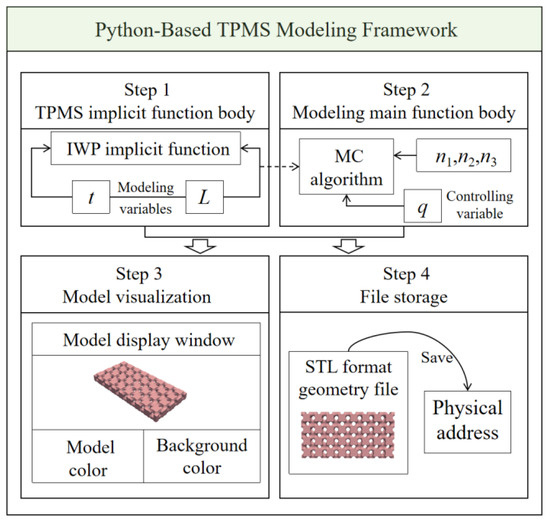
Figure 1.
Schematic framework of the TPMS geometric modeling by the Python program.
Using the above modeling program, [n1, n2, n3] is set as [1, 4, 8], the number of IWP modeling units in the x-direction is set to 1, in the y-direction to 4, and in the z-direction to 8. The parameter q is set between 50 and 100 to ensure good modeling quality. The variable L is fixed as a constant value of 5, meaning each IWP unit has dimensions of 5 × 5 × 5 mm. By adjusting the value of parameter C, IWP structures with different porosities can be obtained. As shown in Equation (2), the volume fraction of the TPMS structure is defined as the ratio of the volume of the solid region occupied by the TPMS model to the total modeling area. Figure 2 shows the two IWP structures with volume fractions of 60% and 30%, respectively.
where represents the values of the components in the x, y, and z directions, and is the volume of the solid TPMS structure calculated by the program.

Figure 2.
IWP structure with (a) a volume fraction of 60%, and (b) a volume fraction of 30%.
2.2. Fabrication Process of Interpenetrating Phase Composites
The fabrication of interpenetrating phase composites involves two main steps: First, the manufacturing of the scaffold structure. Using selective laser melting (SLM) additive manufacturing technology and Ti6Al4V powder as the material, a three-dimensional continuous lattice scaffold based on the TPMS structure is precisely fabricated, ensuring high precision and excellent structural performance, shown in Figure 3a. The second step is the casting of the infiltrated phase. Taking advantage of the good fluidity and low melting point of the AlSi12 alloy, the infiltration casting method is used to fully fill the Al alloy infiltrated phase within the matrix, ensuring a strong bond between the infiltrated part and the scaffold structure.
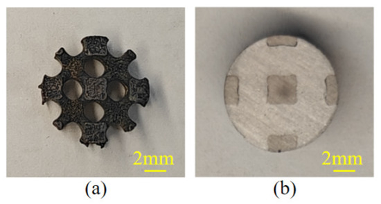
Figure 3.
(a) Fabricated TPMS IWP structure, and (b) Ti/Al IPC specimen.
The Ti6Al4V powder used to fabricate the TPMS scaffold has been widely applied in many fields, and its process parameters have been extensively tested and verified to consistently produce high-quality parts [24]. Due to its combination of low density and high strength, it is an ideal material for lightweight design [25]. The chemical components of Ti6Al4V are shown in Table 1.

Table 1.
Chemical composition of Ti6Al4V (Wt %).
After the heat treatment of the scaffold structure, the AlSi12 bulk infiltrated phase is melted in an electric furnace (melting temperature 750 °C, melting time 30 min). AlSi12 has good fluidity, making it highly suitable for casting [26]. The main components of AlSi12 are shown in Table 2. The molten aluminum is then poured into a heat-insulated graphite mold containing the scaffold structure. During the casting process, ultrasonic equipment is used to assist in ensuring a closer bond between the infiltrated phase and the scaffold. After casting, the sample is naturally cooled. Since the mechanical testing requires samples with regular geometries, the cast parts cannot directly meet the testing conditions after cooling. Therefore, in this study, an electrical discharge wire-cutting machine (Taizhou Tengshun CNC Machine Co., Ltd., Taizhou, China, DK7735) is used to cut the castings into cylindrical samples with the required dimensions, as shown in Figure 3b.

Table 2.
Chemical composition of AlSi12 (Wt %).
2.3. Heat Treatment Process of the Infiltrated Phase
To eliminate the residual stress in the Ti scaffold, it is subjected to heat treatment after SLM. Similarly, the infiltrated phase also requires heat treatment after casting to improve its mechanical properties. Based on previous studies [27,28], a heat treatment process is developed, as shown in Figure 4. After 16 h of homogenization treatment, the temperature is immediately increased for solution strengthening for 1 h. After solution strengthening, quenching is performed by water quenching, with the cooling temperature set at 80 °C. After quenching, the sample is left to dry before being subjected to artificial aging for 4.5 h. After artificial aging, the sample is cooled by air cooling. The homogenization treatment increases the peak stress and plasticity of the material [29]. Solution strengthening and artificial aging significantly improve the yield strength and tensile strength of the cast Al-Si alloy. This is why the heat treatment process results in a more uniform and finer second phase and reduces porosity in the cast Al-Si alloy [27]. Additionally, since the heat treatment temperature for Al alloys is significantly lower than that for Ti alloys, it can be assumed that this heat treatment process has no effect on the microstructure of the Ti alloy, which is further verified through the microstructural characterization of the interface in the results section.
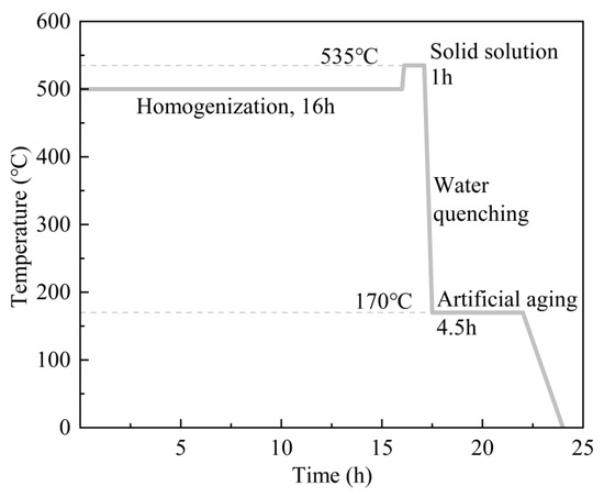
Figure 4.
Heat treatment process diagram.
After the heat treatment of the infiltrated phase, the samples need to be polished. This is achieved by sequentially polishing with 320#, 600#, 1500#, and 2000# sandpaper until the sample surface shows no visible scratches. Then, the samples are ultrasonically cleaned with alcohol to achieve the desired final sample.
2.4. Microstructural Characterization Methods
To verify the effectiveness of the Ti/Al interpenetrating phase composite fabrication process, this study uses a Tescan Mira4 field emission scanning electron microscope (Scanning Electron Microscope, SEM, Brno, Czech Republic) to characterize the microstructure of the Ti/Al interpenetrating phase composite. The SEM accelerating voltage is set to 20 kV to ensure high-resolution images, allowing the observation of the microstructure of the material’s surface and bonding areas. To further analyze the elemental composition and distribution at the Ti/Al interface, the study also employs the Oxford Instruments Xplore30 AZtecOne energy-dispersive spectrometer (Energy Dispersive Spectrometer, EDS, Abingdon, UK) attached to the SEM for elemental analysis. Additionally, a Bruker D8 Advance X-ray diffraction (X-Ray Diffraction, XRD, Karlsruhe, Germany) system is used to scan the composite material’s bonding surface, enabling an in-depth analysis of the phase composition at the interface. The formation of these new phases not only affects the microstructure of the composite material but may also significantly alter its mechanical properties, corrosion resistance, and thermal stability.
2.5. High-Strain-Rate Test Method
The high-strain-rate dynamic mechanical properties of Ti/Al IPC were tested using the SHPB test system. The SHPB test system typically consists of a drive system, a projectile, an incident bar, a transmission bar, a damper, and a data acquisition system (including velocity sensors and strain gauges), as shown in Figure 5. Mechanical properties are reported as mean ± standard deviation from three repeated tests, demonstrating good reproducibility.

Figure 5.
Main components of the SHPB test apparatus.
To reduce the errors caused by determining the waveform starting point and for computational convenience, the stress–strain response curve of the sample is calculated using the reflected wave and transmitted wave method in the two-wave technique. Based on the above assumptions, the incident strain , reflected strain , and transmitted strain satisfy the following conditions:
The strain rate is then calculated based on the velocity difference between the two ends of the specimen
where and represent the velocities at the incident bar end and the transmission bar end of the specimen, respectively; is the initial length of the specimen; is the stress wave propagation velocity in the bar.
By integrating over time, the strain–time curve of the specimen is obtained, as shown in the following equation:
When the stress wave reaches the specimen, the forces acting on the transmission bar and the specimen are equal. Based on this, the stress–time curve of the specimen can be calculated as
where and represent the cross-sectional areas of the specimen and the pressure bar, respectively, and is the elastic modulus of the bar.
2.6. Evaluation Indicators for Dynamic Mechanical Properties
Quantitative criteria enable a clearer assessment of the dynamic mechanical performance of a structure. Researchers have proposed several related evaluation metrics [29], primarily including the following. The specific energy absorption (SEA), known as relative energy absorption, refers to the amount of energy absorbed per unit mass of the material and is defined by the following equation
where represents the ultimate tensile strain at which the material reaches its ultimate tensile strength (UTS), and M denotes the mass of the material. It is important to note that this equation is only valid before a structural collapse occurs, i.e., before reaching the UTS. After the collapse, the structure enters a densification stage, during which it can still absorb a large amount of energy. However, the impact force at this stage becomes significantly higher, which may pose safety risks to the protected object and is therefore considered an ineffective form of energy absorption [30].
The crushing force efficiency (CFE) measures the ability of material to resist failure under compressive loading or impact forces while minimizing energy loss or structural damage. A higher CFE indicates that the material can absorb and withstand a greater amount of force before failure. It is defined as follows.
where represents the average stress of the material at its UTS.
3. Results
3.1. Effect of Ti Alloy Volume Fraction on the Dynamic Mechanical Behavior of Ti/Al IPC
Figure 6a shows the stress–strain curves of samples with different Ti alloy volume fractions—30% (referred to as IPC30), 60% (IPC60), and pure AlSi12 without Ti alloy-tested—at a strain rate of 2800 s−1. Comparing IPC30 and IPC60, Figure 6a,b reveal that when the Ti alloy volume fraction is doubled, the equivalent elastic modulus of the IPC, as determined from the linear elastic region based on Hooke’s law, increases by 65%, the yield strength increases by 66%, and the UTS increases by 151%—a remarkable improvement. As shown in Figure 6c, the SEA of IPC60 increases by 111% compared to IPC30, whereas the crushing force efficiency shows almost no change. These observations indicate that the Ti alloy scaffold serves as the primary load-bearing structure of the IPC, and its volume fraction largely determines the composite’s dynamic mechanical behavior. In addition, since IPC30 and IPC60 share similar structural configurations, their deformation under high-strain-rate loading is also similar, resulting in comparable crushing force efficiency.
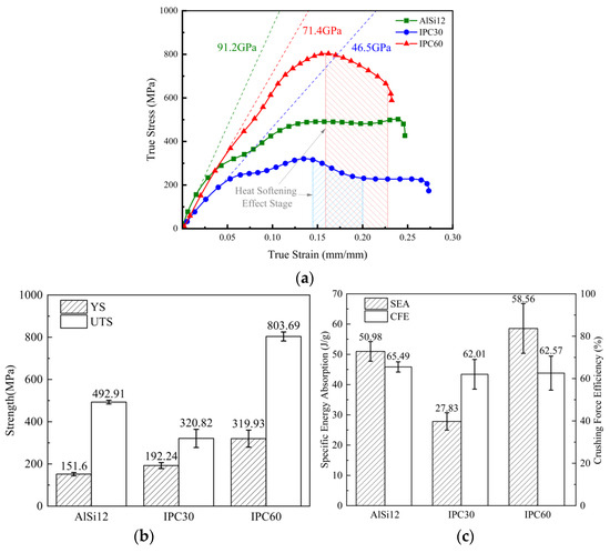
Figure 6.
Dynamic mechanical behavior of the three materials at a strain rate of 2800 s−1 with (a) stress–strain curves, (b) yield strength and UTS, and (c) SEA and CFE.
Comparing the dynamic mechanical performance indicators of AlSi12 and IPC30 under high-strain-rate deformation, Figure 6a reveals that, in comparison with AlSi12, IPC30 exhibits lower equivalent elastic modulus, UTS, and SEA. This outcome can be attributed to two main reasons: First, the interpenetrating structure between the Ti and Al alloys may result in a bonding strength lower than the UTS of the Al alloy alone, thereby weakening the material’s resistance to failure but also enhancing the ductility of IPC30. Secondly, although IPC30 contains Ti alloy components, the relatively low Ti volume fraction means that mechanical behavior is still predominantly influenced by the Al alloy.
At higher strain rates, both IPC30 and IPC60 exhibit a sharp drop in stress after reaching peak stress, as shown in the shaded region of Figure 6a. This is attributed to thermal softening effects. Guan et al. [30] reported that in this stage, the strain hardening rate becomes negative, meaning thermal softening outweighs strain hardening, and thermal softening begins to dominate the deformation process, leading to the onset of localized adiabatic shear. Additionally, this behavior may be due to the lower thermal conductivity of Ti alloy compared to Al alloy. Under dynamic loading, Ti alloy cannot effectively dissipate heat in a short time, resulting in localized temperature rise and deterioration of mechanical performance—an effect not observed in AlSi12. For IPC30, as strain hardening gradually increases, a plateau appears when the true strain reaches 0.20. This indicates a stage where the effects of thermal softening and strain hardening offset each other. The system remains in a steady state until failure, where a balance is achieved among strain hardening, dynamic hardening, and thermal softening. In contrast, IPC60 fails to exhibit a distinct plateau phase as its ductility is relatively poor—it fails before the onset of the plateau stage.
3.2. Effect of Strain Rate on the Dynamic Mechanical Behavior of Ti/Al IPC
Figure 7a,b show the stress–strain curves of IPC30 and IPC60 at strain rates of 1800 s−1 and 2800 s−1, respectively. As shown in Figure 7a and Table 3, it can be observed that when the strain rate increases from 1800 s−1 to 2800 s−1, the equivalent elastic modulus, yield strength, and UTS of IPC30 all reduce, indicating a significant dynamic softening effect. This may be attributed to the fact that AlSi12, as the major component of IPC30, exhibits a pronounced dynamic softening behavior [31], which has a notable influence on the overall performance of IPC30. However, changes in strain rate do not cause noticeable fluctuation in the SEA of IPC30. Although IPC30 shows a reduction in ultimate compressive strength at higher strain rates, its ductility improves, compensating for the decline in strength and thus maintaining its energy absorption capacity. This enhancement in ductility is attributed to the increased work hardening coefficient under high strain rates, which leads to more uniform material deformation [20]. As shown in Figure 7b and Table 3, IPC60 exhibits a distinct response to increasing strain rate results compared to IPC30. Specifically, its yield strength, UTS, and SEA all increase. This distinct behavior is primarily governed by Ti6Al4V—the predominant constituent of IPC60—which is characterized by a typical strain hardening response [20,32].
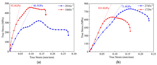
Figure 7.
Stress–strain curves of IPC under different strain rates for (a) IPC30 and (b) IPC60.

Table 3.
Dynamic mechanical properties of IPC30 and IPC60 under different strain rates.
The strain rate sensitivity (SRS) describes how strain rate influences the stress response of a material under constant strain and temperature conditions [33], and it is denoted as
where is the fitted linear strain rate sensitivity exponent. According to Table 3, IPC30 exhibits a significantly higher SRS at a strain rate of 1800 s−1 compared to 2800 s−1. This observation is consistent with the findings of Hu et al. [34], who reported that under the combined effects of tension and shear, SRS tends to decrease as plastic strain increases. In Figure 7a, IPC30 shows higher plastic strain at a strain rate of 2816 s−1 than at 1860 s−1, confirming this trend. This behavior is also observed in IPC60; however, due to the dominant strain hardening effect of Ti6Al4V, the decrease in SRS caused by increased plastic strain is partially offset. As a result, the SRS decline in IPC60 is less pronounced than that in IPC30.
Table 3 shows dynamic mechanical properties of IPC30 and IPC60 under different strain rates data, and the data are presented as mean ± standard deviation from at least three independent tests. It is worth noting that the CFE data in Table 3 are almost identical, which may be attributed to the interpenetrating structure of Ti/Al IPC. These materials exhibit similar deformation patterns that are not significantly affected by changes in the volume fraction of Ti alloy or strain rate. The study reported by Mu et al. [35] also indicates that under dynamic impact conditions, the CFE of IPC is minimally influenced by changes in the volume fraction of the matrix scaffold structure.
3.3. Microscopic Characterization of the Interface Layer
As shown in Figure 8a, it can be observed that the fabricated IPC exhibits a clear interface region. In Figure 8b,c, the bonding surface between the Ti and Al phases is shown at magnifications of 200× and 5000×, respectively. From these images, it is evident that the transition region at the interface between the two phases is well bonded, and the interface is not perfectly smooth but exhibits some roughness. This roughness allows for a larger contact area between the Al alloy and the matrix structure during the melting process, thus enhancing the bonding strength. At the higher magnification of 5000×, a more detailed view of the interface layer between the two phases is provided. This image further reveals that there are no obvious cracks at the interface, and instead, a transition zone is visible, indicating that the bonding between the Ti and Al phases is good and there are no issues of incomplete bonding at the interface. Figure 8d shows the EDS element distribution based on the region from Figure 8c. It can be observed that the Al element is concentrated in the right region of the composite material, and its distribution in this area is uniform, indicating that the IPC material produced by the infiltration casting method is effective. This is consistent with the Al phase material shown in Figure 8c. Moreover, the Al element on the left edge does not show a neat distribution, suggesting that a chemical reaction may have occurred between Al and Ti, which leads to an irregular interface. The Ti element is clearly concentrated in the left side of the image, and its distribution is relatively uniform. It can be seen that the concentration of Ti at the right edge is sparser, which requires further analysis of the composition phase at the interface using X-ray Diffraction (XRD). Figure 8e shows the phase diffraction peaks of the Ti/Al IPC surface obtained through XRD analysis. The XRD scan range is 2θ = 10–90°, with a scan speed of 5°/min and a grazing angle of 0.5°. Using the phase analysis software MDI Jade 9, the phase diffraction peaks are analyzed and labeled. It is found that, in addition to pure Ti and Al, the surface of the interpenetrating phase composite also generates three intermetallic compounds: TiAl [36], Al3Ti17 [37], and Al6Ti19. This indicates that during the fabrication process, Ti and Al underwent a metallurgical reaction, producing intermetallic compounds, which further strengthen the bonding between the two phases and validated the effectiveness and reliability of the fabrication process.
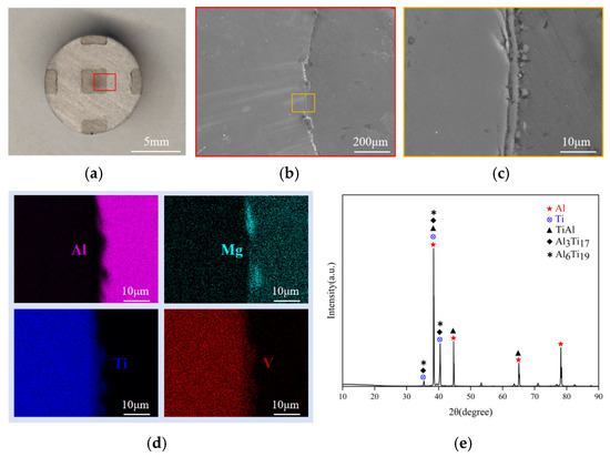
Figure 8.
(a) Ti/Al IPC specimen, (b) 200× magnification at the interface, (c) 5000× magnification at the interface, (d) element distribution based on the (c) region, and (e) phase composition of the Ti/Al IPC specimen.
3.4. Damage Mechanism of Ti/Al IPC Under High-Strain-Rate Deformation
The macroscopic damage morphology of the specimens after the SHPB dynamic test, as shown in Figure 9a,b, indicates that when the impact load is applied along the red arrow direction (the axial direction of the specimen), the Al alloy experiences significant shear slip due to plastic deformation at high strain rates, causing material scattering along the yellow arrow direction. This non-coordinated deformation generates localized stress at the Ti/Al interface. Under the coupling of the inertial effect and interface shear stress, rapid delamination of the interface is triggered. It is worth noting that the IPC60 specimen, due to its higher Ti alloy volume fraction, exhibits a significant improvement in the mechanical interlocking effect of the interface due to the three-dimensional interpenetrating network structure. Additionally, the high modulus characteristic of the Ti phase and its topological continuity optimize the stress transfer path, effectively suppressing the plastic flow of the Al alloy phase. Therefore, under the same loading conditions, the crack propagation in the IPC60 specimen is lower than that in IPC30, resulting in better impact delamination resistance. Figure 9c shows the IPC deformation schematic; under the impact load (direction of the blue arrow), the Al alloy scatters along the direction of the yellow arrow, causing the Ti/Al interface to rapidly delaminate and fall off. IPC60, with a higher volume fraction of Ti alloy, shows a stronger resistance to delamination, so the impact load has a weaker effect on its peeling.
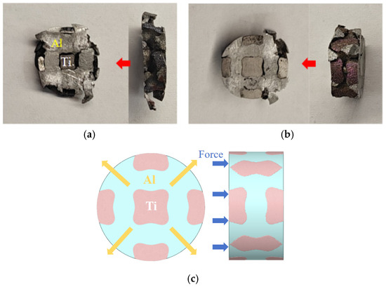
Figure 9.
Macro morphology of IPC after SHPB test for (a) IPC30, (b) IPC60, and (c) IPC deformation schematic.
Figure 10 shows the microscopic morphology of IPC60 after SHPB testing. At higher magnification, as shown in Figure 10c,d, both regions actually exhibit dimples, although in different forms. This may be why the TPMS structure in the IPC material not only bears compressive stress but also shear stress under high-strain-rate deformation. In Figure 10d, the dimples at the fracture surface exhibit a parabolic shape, which is characteristic of shear stress-induced fracture. The direction of the parabolic bulge also corresponds to the direction of the shear force applied to the matrix on one side of the fracture surface.
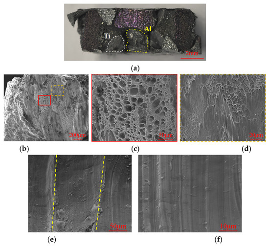
Figure 10.
Morphology of IPC after SHPB test for (a) macro morphology, (b) Ti alloy at 150×, (c) Ti alloy at 1000×, (d) Ti alloy at 2000×, (e) Al alloy at 1000×, and (f) Al alloy at 5000×.
As shown in Figure 10e, cracks in the Al phase propagate along the slip planes, forming mutually parallel crystal planes at different heights, as indicated by the yellow lines. This is one of the typical features of cleavage steps, a characteristic of brittle fracture. Brittle fracture can be categorized into intergranular fracture and transgranular fracture. Transgranular fracture refers to cracks that propagate through the grain interior, while intergranular (grain boundary) fracture refers to cracks propagating along the grain boundaries. Generally, the bonding strength at the grain boundaries is higher than that within the grains, making the grain boundaries a strengthening factor. In addition, local shear slip surfaces are observed in Figure 10f. Under dynamic loading, the intensification of local shear bands leads to shear lips and quasi-cleavage planes, which further reduce the material’s deformation [38].
4. Discussion
Under high-strain-rate (102–104 s−1) dynamic loading conditions, the relationship between strain rate and specific strength of materials is often of primary concern, as it is a core indicator for evaluating impact resistance. Figure 11 compares the specific strength of IPC30, IPC60, and several advanced materials [9,34,39,40,41,42,43] based on the equivalent strain rate in a logarithmic scale (log10ε). According to the experimental data from Table 3, the maximum specific strengths of IPC30 and IPC60 with the TPMS-IWP matrix structure reach 169.12 MPa and 242.81 MPa, respectively, in the strain rate range of 1800–2800 s−1, significantly higher than that of other advanced materials. This phenomenon can be attributed to the dual reinforcement mechanism of Ti/Al IPC: first, the three-dimensional continuous network of the TPMS topology effectively transfers the load and suppresses stress localization through the mechanical interlocking effect. Secondly, the optimized interface bonding strength between the Ti and Al phases reduces stress mismatch during the dynamic deformation process, allowing the material to maintain interface integrity without failure over a larger strain range under high-speed loading.
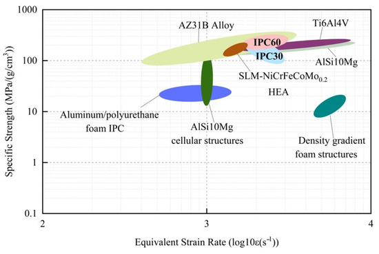
Figure 11.
Performance comparison of IPC30, IPC60, and advanced materials [9,34,39,40,41,42,43].
5. Conclusions
In this study, IPCs based on TPMS are generated using Python modeling, and two types of IPCs are fabricated by additive manufacturing and infiltration casting methods. The dynamic mechanical properties of IPC are investigated and compared under different Ti alloy volume fractions and strain rates using SHPB tests. The main conclusions are drawn as follows:
- (1)
- At high strain rates, as the Ti alloy volume fraction increases in IPC, comparing IPC30 and IPC60, the equivalent elastic modulus of IPC increases by 65%, yield strength increases by 66%, UTS increases by 151%, and SEA increases by 111%. Due to the thermal softening effect, both IPC with different volume fractions exhibit a sharp decrease in stress after reaching UTS. In contrast, IPC30′s equivalent elastic modulus, UTS, and SEA are lower than those of AlSi12, but its yield strength is higher than that of AlSi12.
- (2)
- As the strain rate increases, IPC30 and IPC60 exhibit opposite dynamic mechanical behaviors. IPC30′s dynamic mechanical performance is dominated by AlSi12, showing a dynamic softening effect, while IPC60 is dominated by Ti6Al4V, displaying a dynamic hardening effect. Both composites’ strain rate sensitivity decreases as plastic strain increases. Under high-strain-rate deformation, the interpenetrating structure characteristics of Ti/Al IPC make the crushing force efficiency unaffected by changes in Ti alloy volume fraction and strain rate.
- (3)
- Microstructural characterization serves to validate the reliability of the fabrication process and enable the analysis of distinct fracture morphologies in the two phases of IPC60 under high-strain-rate deformation conditions. Specifically, the Ti alloy phase exhibits ductile fracture, whereas the Al alloy phase exhibits brittle fracture behavior.
Author Contributions
Conceptualization, Z.L. and L.Y.; methodology, Z.Z. and J.T.; software, J.T. and J.L.; validation, Z.L., Z.Z. and J.T.; formal analysis, J.T.; investigation, Z.Z. and J.T.; resources, Z.Z.; data curation, J.T.; writing—original draft preparation, Z.Z. and J.T.; writing—review and editing, Z.L., L.Y., L.Z. and S.X.; visualization, Z.Z.; supervision, Z.L., L.Y., S.X. and L.Z.; project administration, Z.L.; funding acquisition, Z.L. All authors have read and agreed to the published version of the manuscript.
Funding
The authors wish to gratefully acknowledge the financial support from the National Natural Science Foundation of China (Grant No. 52105418), the Natural Science Foundation of Hunan Province (Grant No. 2023JJ20069), and the key scientific research project of Hunan Provincial Department of Education (Grant No. 23A0001).
Data Availability Statement
The original contributions presented in this study are included in the article. Further inquiries can be directed to the corresponding author.
Conflicts of Interest
The authors declare no conflicts of interest.
Abbreviations
The following abbreviations are used in this manuscript:
| IPC | Interpenetrating phase composites |
| TPMS | Triply periodic minimal surface |
| IWP | I-wrapped package |
| SHPB | Split Hopkinson pressure bar |
| SLM | Selective laser melting |
| SEA | Specific energy absorption |
| UTS | Ultimate tensile strength |
| SRS | Strain rate sensitivity |
| CFE | Crushing force efficiency |
| C | Controls the porosity of the structure |
| L | Defines the size of the unit cell |
| The volume of the solid TPMS structure calculated by the program | |
| The incident strain | |
| The reflected strain | |
| The stress wave propagation velocity in the bar. | |
| The elastic modulus of the bar. | |
| The ultimate tensile strain at which the material reaches its UTS | |
| M | The mass of the material |
| The average stress of the material at its UTS | |
| The fitted linear strain rate sensitivity exponent | |
| The original radius of the specimen | |
| The radius of the bar | |
| The velocities at the incident bar end of the specimen | |
| The velocities at the transmission bar end of the specimen | |
| The initial length of the specimen |
References
- Lin, Y.; Wang, D.; Yang, C.; Zhang, W.; Wang, Z. An Al-Al interpenetrating-phase composite by 3D printing and hot extrusion. Int. J. Miner. Metall. Mater. 2023, 30, 678–688. [Google Scholar] [CrossRef]
- Sun, X.; Jiang, F.; Yuan, D.; Wang, G.; Tong, Y.; Wang, J. High damping capacity of AlSi10Mg-NiTi lattice structure interpenetrating phase composites prepared by additive manufacturing and pressureless infiltration. J. Alloys. Compd. 2022, 905, 164075. [Google Scholar] [CrossRef]
- Yao, B.; Zhou, Z.; Duan, L. Anisotropic compressive properties and energy absorption of metal–resin interpenetrating phase composites. J. Mater. Res. 2018, 33, 2477–2485. [Google Scholar] [CrossRef]
- Zhang, M.; Yu, Q.; Wang, H.; Zhang, J.; Wang, F.; Zhang, Y.; Xu, D.; Liu, Z.; Zhang, Z.; Ritchieet, R.O. Phase-transforming Ag-NiTi 3-D interpenetrating-phase composite with high recoverable strain, strength and electrical conductivity. Appl. Mater. Today 2022, 29, 101639. [Google Scholar] [CrossRef]
- Taylor, S.V.; Gonzales, M.; Cordero, Z.C. Shock response of periodic interpenetrating phase composites. APL Mater. 2022, 10, 111119. [Google Scholar] [CrossRef]
- Yang, X.; Huang, W.; Zhan, D.; Ren, D.; Ji, H.; Liu, Z.; Wang, Q.; Zhang, N.; Zhang, Z. Biodegradability and Cytocompatibility of 3D-Printed Mg-Ti Interpenetrating Phase Composites. Front. Bioeng. Biotechnol. 2022, 10, 891632. [Google Scholar] [CrossRef]
- Zhou, C.; Zhou, Y.; Zhang, Q.; Meng, Q.; Zhang, L.; Kobayashi, E.; Wu, G. Near-zero thermal expansion of ZrW2O8/Al–Si composites with three dimensional interpenetrating network structure. Compos. Part B Eng. 2021, 211, 108678. [Google Scholar] [CrossRef]
- Okulov, I.V.; Geslin, P.-A.; Soldatov, I.V.; Ovri, H.; Joo, S.-H.; Kato, H. Anomalously low modulus of the interpenetrating-phase composite of Fe and Mg obtained by liquid metal dealloying. Scr. Mater. 2019, 163, 133–136. [Google Scholar] [CrossRef]
- Fan, Z.; Zhang, B.; Liu, Y.; Suo, T.; Xu, P.; Zhang, J. Interpenetrating phase composite foam based on porous aluminum skeleton for high energy absorption. Polym. Test. 2021, 93, 106917. [Google Scholar] [CrossRef]
- Zheng, Y.; Zhou, Y.; Feng, Y.; Teng, X.; Yan, S.; Li, R.; Yu, W.; Huang, Z.; Li, S.; Li, Z. Synthesis and mechanical properties of TiC-Fe interpenetrating phase composites fabricated by infiltration process. Ceram. Int. 2018, 44, 21742–21749. [Google Scholar] [CrossRef]
- Singh, A.; Al-Ketan, O.; Karathanasopoulos, N. Mechanical performance of solid and sheet network-based stochastic interpenetrating phase composite materials. Compos. Part B Eng. 2023, 251, 110478. [Google Scholar] [CrossRef]
- Zhang, M.; Zhao, N.; Yu, Q.; Liu, Z.; Qu, R.; Zhang, J.; Li, S.; Ren, D.; Berto, F.; Zhang, Z.; et al. On the damage tolerance of 3-D printed Mg-Ti interpenetrating-phase composites with bioinspired architectures. Nat. Commun. 2022, 13, 3247. [Google Scholar] [CrossRef]
- Guo, X.; Ding, J.; Li, X.; Qu, S.; Hsi Fuh, J.Y.; Lu, W.F.; Song, X.; Zhai, W. Interpenetrating phase composites with 3D printed triply periodic minimal surface (TPMS) lattice structures. Compos. Part B Eng. 2023, 248, 110351. [Google Scholar] [CrossRef]
- San Marchi, C.; Kouzeli, M.; Rao, R.; Lewis, J.A.; Dunand, D.C. Alumina–aluminum interpenetrating-phase composites with three-dimensional periodic architecture. Scr. Mater. 2003, 49, 861–866. [Google Scholar] [CrossRef]
- Holovenko, Y.; Kollo, L.; Saarna, M.; Rahmani, R.; Soloviova, T.; Antonov, M.; Prashanth, K.G.; Cygan, S.; Veinthal, R. Effect of lattice surface treatment on performance of hardmetal-titanium interpenetrating phase composites. Int. J. Refract. Met. Hard Mater. 2020, 86, 105087. [Google Scholar] [CrossRef]
- Cheng, J.; Gussev, M.; Allen, J.; Hu, X.; Moustafa, A.R.; Splitter, D.A.; Shyam, A. Deformation and failure of PrintCast A356/316 L composites: Digital image correlation and finite element modeling. Mater. Des. 2020, 195, 109061. [Google Scholar] [CrossRef]
- Feng, X.-Q.; Tian, Z.; Liu, Y.-H.; Yu, S.-W. Effective Elastic and Plastic Properties of Interpenetrating Multiphase Composites. Appl. Compos. Mater. 2004, 11, 33–55. [Google Scholar] [CrossRef]
- Zhang, Y.; Hsieh, M.-T.; Valdevit, L. Mechanical performance of 3D printed interpenetrating phase composites with spinodal topologies. Compos. Struct. 2021, 263, 113693. [Google Scholar] [CrossRef]
- Feng, J.; Fu, J.; Yao, X.; He, Y. Triply periodic minimal surface (TPMS) porous structures: From multi-scale design, precise additive manufacturing to multidisciplinary applications. Int. J. Extrem. Manuf. 2022, 4, 022001. [Google Scholar] [CrossRef]
- Biswas, N.; Ding, J.L.; Balla, V.K.; Field, D.P.; Bandyopadhyay, A. Deformation and fracture behavior of laser processed dense and porous Ti6Al4V alloy under static and dynamic loading. Mater. Sci. Eng. A 2012, 549, 213–221. [Google Scholar] [CrossRef]
- Alkhatib, S.E.; Sercombe, T.B. High strain-rate response of additively manufactured light metal alloys. Mater. Des. 2022, 217, 110664. [Google Scholar] [CrossRef]
- Chang, H.; Binner, J.; Higginson, R.; Myers, P.; Webb, P.; King, G. High strain rate characteristics of 3-3 metal–ceramic interpenetrating composites. Mater. Sci. Eng. A 2011, 528, 2239–2245. [Google Scholar] [CrossRef][Green Version]
- Yoo, D.-J. Computer-aided porous scaffold design for tissue engineering using triply periodic minimal surfaces. Int. J. Precis. Eng. Manuf. 2011, 12, 61–71. [Google Scholar] [CrossRef]
- Shipley, H.; McDonnell, D.; Culleton, M.; Coull, R.; Lupoi, R.; O’Donnell, G.; Trimble, D. Optimisation of process parameters to address fundamental challenges during selective laser melting of Ti-6Al-4V: A review. Int. J. Mach. Tools Manuf. 2018, 128, 1–20. [Google Scholar] [CrossRef]
- Sun, J.; Yang, Y.; Wang, D. Mechanical properties of a Ti6Al4V porous structure produced by selective laser melting. Mater. Des. 2013, 49, 545–552. [Google Scholar] [CrossRef]
- Lipinski, T. Mechanical properties of AlSi12 alloy with aluminium bronze. In Proceedings of the 16th International Scientific Conference Engineering for Rural Development, Jelgava, Latvia, 24–26 May 2017. [Google Scholar] [CrossRef]
- Cheng, W.; Liu, C.Y.; Huang, H.F.; Zhang, L.; Zhang, B.; Shi, L. High strength and ductility of Al–Si–Mg alloys fabricated by deformation and heat treatment. Mater. Charact. 2021, 178, 111278. [Google Scholar] [CrossRef]
- Arabpour, M.; Boutorabi, S.M.A.; Saghafian, H. Effect of Ablation Casting Process on the Microstructural Parameters and Tensile Properties of A413 and A356 Alloys. Int. J. Met. 2024, 18, 1619–1632. [Google Scholar] [CrossRef]
- Yin, H.; Liu, Z.; Dai, J.; Wen, G.; Zhang, C. Crushing behavior and optimization of sheet-based 3D periodic cellular structures. Compos. Part B Eng. 2020, 182, 107565. [Google Scholar] [CrossRef]
- Guan, X.R.; Chen, Q.; Qu, S.J.; Cao, G.J.; Wang, H.; Ran, X.D.; Feng, A.; Chen, D. High-strain-rate deformation: Stress-induced phase transformation and nanostructures in a titanium alloy. Int. J. Plast. 2023, 169, 103707. [Google Scholar] [CrossRef]
- Ponnusamy, P.; Masood, S.H.; Ruan, D.; Palanisamy, S.; Rashid, R.A.R.; Mukhlis, R.; Edwards, N.J. Dynamic compressive behaviour of selective laser melted AlSi12 alloy: Effect of elevated temperature and heat treatment. Addit. Manuf. 2020, 36, 101614. [Google Scholar] [CrossRef]
- Waymel, R.F.; Chew, H.B.; Lambros, J. Loading Orientation Effects on the Strength Anisotropy of Additively-Manufactured Ti-6Al-4V Alloys under Dynamic Compression. Exp. Mech. 2019, 59, 829–841. [Google Scholar] [CrossRef]
- Qin, F.; Du, S.; Li, Y.; Zhao, X.; Xu, Y. Effects of strain rate on dynamic deformation behavior and microstructure evolution of Fe-Mn-Cr-N austenitic stainless steel. Mater. Charact. 2024, 212, 113975. [Google Scholar] [CrossRef]
- Hu, H.; Xu, Z.; Dou, W.; Huang, F. Effects of strain rate and stress state on mechanical properties of Ti-6Al-4V alloy. Int. J. Impact Eng. 2020, 145, 103689. [Google Scholar] [CrossRef]
- Mu, Y.; Jin, Y.; Ji, H.; Luo, J.; Li, G.; Xu, M.; Li, H.; Deng, B.; Du, J. Mechanical performance of interpenetrating phase composites with multi-sheet lattice structures. Int. J. Mech. Sci. 2024, 276, 109369. [Google Scholar] [CrossRef]
- Novoselova, T.; Malinov, S.; Sha, W.; Zhecheva, A. High-temperature synchrotron X-ray diffraction study of phases in a gamma TiAl alloy. Mater. Sci. Eng. A 2004, 371, 103–112. [Google Scholar] [CrossRef]
- Kravchenko, Y.; Borysiuk, V.; Pogrebnjak, A.; Kylyshkanov, M.; Iatsunskyi, I.; Smyrnova, K. Characteristics of Arc-PVD TiAlSiY and (TiAlSiY)N coatings. In Proceedings of the 2017 IEEE 7th International Conference Nanomaterials: Application & Properties (NAP), Zatoka, Ukraine, 10–15 September 2017; pp. 01FNC02-1–01FNC02-4. [Google Scholar] [CrossRef]
- Chandran, S.; Liu, W.; Lian, J.; Münstermann, S.; Verleysen, P. Strain rate dependent plasticity and fracture of DP1000 steel under proportional and non-proportional loading. Eur. J. Mech.-A/Solids 2022, 92, 104446. [Google Scholar] [CrossRef]
- Ahmad, I.R.; Shu, D.W. Compressive and constitutive analysis of AZ31B magnesium alloy over a wide range of strain rates. Mater. Sci. Eng. A 2014, 592, 40–49. [Google Scholar] [CrossRef]
- Nurel, B.; Nahmany, M.; Frage, N.; Stern, A.; Sadot, O. Split Hopkinson pressure bar tests for investigating dynamic properties of additively manufactured AlSi10Mg alloy by selective laser melting. Addit. Manuf. 2018, 22, 823–833. [Google Scholar] [CrossRef]
- Huang, Y.; Xie, Z.; Li, W.; Chen, H.; Liu, B.; Wang, B. Dynamic mechanical properties of the selective laser melting NiCrFeCoMo0.2 high entropy alloy and the microstructure of molten pool. J. Alloys Compd. 2022, 927, 167011. [Google Scholar] [CrossRef]
- Pawlowski, P.; Stanczak, M.; Broniszewska-Wojdat, P.; Blanc, L.; Fras, T.; Rusinek, A. Energy-absorption capacity of additively manufactured AlSi10Mg cellular structures subjected to a blast-induced dynamic compression–experimental and numerical study. Int. J. Impact Eng. 2025, 198, 105216. [Google Scholar] [CrossRef]
- Gao, Y.; Xu, W.; Wang, C.; Qi, F.; Xue, S. Investigation on shock wave mitigation performance and crashworthiness of density gradient foam structures. Int. J. Impact Eng. 2025, 197, 105187. [Google Scholar] [CrossRef]
Disclaimer/Publisher’s Note: The statements, opinions and data contained in all publications are solely those of the individual author(s) and contributor(s) and not of MDPI and/or the editor(s). MDPI and/or the editor(s) disclaim responsibility for any injury to people or property resulting from any ideas, methods, instructions or products referred to in the content. |
© 2025 by the authors. Licensee MDPI, Basel, Switzerland. This article is an open access article distributed under the terms and conditions of the Creative Commons Attribution (CC BY) license (https://creativecommons.org/licenses/by/4.0/).