Abstract
The advancement of non-aqueous redox flow batteries (NARFBs) remains significantly constrained by the absence of membranes with sufficient ionic selectivity and chemical compatibility. Herein, we fabricated flexible membranes incorporating metal–organic framework (MOF) via a solution casting approach. The rigid framework structure of the MOF effectively suppresses membrane swelling in organic solvents. The appropriate structural pore of MOF enables a size-sieving effect toward redox-active materials and supporting electrolyte, thereby reducing material crossover and enhancing the ionic selectivity of the composite membranes. The batteries with the designed composite membranes exhibit a Coulombic efficiency of higher than 99% and significantly improved cycling stability at 10 mA cm−2. The membrane design strategy, employing MOF materials with a structural pore size between the molecular size of the supporting electrolyte and active materials, is universal for NARFB.
1. Introduction
With the rapid increase in global energy demand, the development and utilization of renewable energy sources have received widespread attention [1]. As a novel type of energy storage technology, non-aqueous redox flow batteries (NARFBs) have shown great potential in the fields of grid peaking and renewable energy storage due to the advantages of high energy density, system flexibility, and scalability [2]. As the critical component of NARFBs, the membrane needs to isolate the catholyte and anolyte redox-active materials to reduce self-discharge whilst allowing the transportation of the supporting electrolyte ions [3,4]. Membranes for NARFBs include ceramic membranes, ion-exchange membranes, and porous membranes. Ceramic separators, such as β-alumina and Li1.5Al0.5Ge1.5P3O12 [5,6], exhibit low crossover and thus, high cycling stability. However, their high resistance limits NARFBs to low operational current density [7]. Additionally, low flexibility, brittleness [3], and elevated production costs of ceramic membranes further hinder their widespread adoption in commercial applications. The ion-exchange membranes consist of charged ion-exchange groups, inducing electrostatic repulsion toward counter-ions and thus high ion selectivity. However, the high swelling of the organic polymer backbone in organic solvents leads to changes in the shape and size of the membrane. This morphological instability facilitates the crossover of redox-active species, thereby shortening cycle life [8,9].
Porous membranes, which rely on size-sieving mechanisms to facilitate ion transport, are considered promising candidates for NARFBs. However, their pore sizes are generally much larger than the molecular dimensions of redox-active species, resulting in poor ion selectivity and significant crossover of active materials [10]. To address such challenges, many strategies have been proposed. A common strategy involves incorporating inorganic fillers such as SiO2 or TiO2 into the membrane during fabrication [11,12]. The nanoparticles increase the tortuosity of ion transport pathways, thereby reducing the permeation rate of redox-active species. However, the introduction of additional nanoparticles leads to higher internal resistance and decreased voltage efficiency (VE). Alternatively, dense barrier layers can be constructed on the membrane surface to improve ion selectivity. For instance, two-dimensional materials such as vermiculite nanosheets [13] and metal–organic framework (MOF) nanosheets [14] were deposited onto Celgard-2325 membranes via vacuum filtration. The crossover issue was obviously alleviated, but at the expense of lower VE. In addition, ionic liquids can also be used as functional additives to modify and optimize membrane properties [15]; however, this modification typically reduces the mechanical strength of the membrane.
MOFs have emerged as promising materials in recent years. Composed of central metal atoms and organic ligands, MOFs exhibit regular microporous structures [16]. The special inherent interconnected pore structures provide alternatives to sieve the molecules and thus show great potential in the field of gas separation, catalysis, and energy storage [17,18,19]. Several MOF-based membranes have been prepared for NARFB. A gravity-assisted solvent evaporation method was developed to fabricate a composite membrane by incorporating copper benzene-1,3,5-tricarboxylate (CuBTC) into a Celgard commercial separator [20]. The resultant battery based on the CuBTC/Celgard membrane exhibited a CE of 97% over 20 cycles at 4 mA cm−2. A “rolling dough” strategy was employed to fabricate a porous membrane by incorporating zinc-based MOF (MOF-5) with polytetrafluoroethylene [21]. Such a membrane-based battery demonstrated a CE of 99.7% after 200 cycles at 4 mA cm−2. Those results are encouraging for the application of MOFs in NARFB; however, how to select MOF materials to match the redox-active species and the supporting electrolyte, and thus to obtain high-performance NARFB, remains to be answered.
Our recent investigations have identified N-(naphthalimidoethyl)-N,N-dimethyl-N-ethyl-ammonium bis(trifluoromethanesulfonyl)imide (NI-TFSI) and N-(ferrocenylmethyl)-N,N-dimethyl-N-ethylammonium bis(trifluoromethanesulfonyl)imide (Fc1N112-TFSI) as highly stable redox-active species suitable for NARFBs [22]. Despite their favorable electrochemical properties, the overall battery efficiency remains constrained by severe active species crossover through the membrane. Herein, porous zinc(II) 2-methylimidazolate/polyvinylidene fluoride (ZIF-8/PVDF) composite membranes are specially designed for the battery based on such active materials. The rationale behind this is that the pore size of ZIF-8 is just between that of active materials and supporting electrolyte, which allows the easy transportation of the supporting electrolyte, whereas it effectively hinders the transport of the redox-active species. The resultant batteries exhibit a high CE of 99.2% at 10 mA cm−2 over 100 cycles. Such strategies can be extended to other MOF materials.
2. Experimental
2.1. Materials
The materials include zirconium(IV) tetrachloride (ZrCl4, 98%, Meryer, Shanghai, China); terephthalic acid (C8H6O4, 99.6%, Bide, Shanghai, China); 2-methylimidazole (C4H6N2, 98%, Heowns, Tianjin, China); zinc nitrate hexahydrate (Zn(NO3)2·6H2O, 98%, Damao, Tianjin, China); acetic acid (C2H4O2, 98%, Meryer, Shanghai, China); PVDF (Mw = 530,000, Kynar, King of Prussia, PA, USA); methanol (CH3OH, 99%, Meryer, Shanghai, China); lithium bis (tetrafluoromethylsulfonyl)amide (LiTFSI, 99.5%, Meryer, Shanghai, China); 1,8-naphthalic anhydride (98%, Meryer, Shanghai, China); acetonitrile (MeCN, 99.5%, Meryer, Shanghai, China); tetraethylammonium bromide (TEABr, 99%, Guangfu, Tianjin, China); N,N-Dimethylformamide (DMF, 99%, Meryer, Shanghai, China); acetone (C3H6O, 99%, Jiangtian, Tianjin, China); bromoethane (99%, J&K, Beijing, China); and tetrahydrofuran (THF, 99%, Macklin, Shanghai, China). The compounds tetraethylammonium bis(trifluoromethanesulfonyl)imide (TEATFSI), NI-TFSI, and Fc1N112-TFSI were prepared in accordance with established synthetic methodologies reported in the prior literature [22].
ZIF-8 was synthesized referring to the reported procedures [23]. Briefly, 12.3 g of 2-methylimidazole and 0.744 g of Zn(NO3)2·6H2O were separately dissolved in deionized water. The two solutions were combined and continuously stirred at ambient temperature for 1 h to facilitate a reaction. The resulting product was collected by centrifugation, washed several times with methanol, and subsequently dried in a vacuum oven at 150 °C. zinc(II) benzene-1,4-dicarboxylate (MOF-5) and zirconium(IV) 1,4-benzenedicarboxylate (UiO-66) was synthesized following the reports [24,25].
2.2. Membrane Preparation
In total, 0.255 g ZIF-8 particles was ultrasonically dispersed in acetone. The dispersion was then added to a PVDF slurry (12 wt% PVDF in DMF) and magnetically stirred in a 60 °C water bath for 24 h. After allowing the mixture to stand to eliminate entrapped air bubbles, the slurry was uniformly spread over a glass substrate using a doctor blade with a gap thickness of 500 μm. The membrane was subsequently dried in a vacuum oven at 60 °C. The MOF content in the composite membrane was selected as 10, 20, 30, and 40 wt%. The MOF-5/PVDF and UIO-66/PVDF composite membranes were prepared by a similar procedure with an MOF content of 30%.
2.3. Permeability Test
An H-type diffusion cell was employed to assess the transport behavior of both redox-active species and supporting electrolyte ions across the membrane [14]. A total of 0.05 M acetonitrile solution of either the redox-active species or the supporting electrolyte was added to the left compartment of the diffusion cell, while pure acetonitrile was added to the right compartment. The two chambers were separated by the membrane. At predetermined time intervals, samples were collected from the right compartment for analysis. The concentration of the redox-active species was determined using Ultraviolet-visible spectroscopy (Shimadzu UV2700, Kyoto, Japan), whereas the concentration of the supporting electrolyte was estimated using a calibrated conductivity meter (INESA DDS-307 A, Shanghai, China). The peak wavelengths of 435 nm for Fc1N112-TFSI and 333 nm for NI-TFSI were selected for calculation [22].
2.4. Swelling Ratio Test
The composite membrane was immersed in acetonitrile for 24 h, after which the dimensional change in membrane length was recorded. The swelling ratio (SR) was subsequently determined using Equation (1)
2.5. Electrochemical Test
Cyclic voltammetry (CV) measurements were conducted on a VersaSTAT3 system (Princeton Applied Research, Oak Ridge, TN, USA) employing a 6 mm glassy carbon disk as the working electrode, a Ag/Ag+ electrode (0.5 M AgNO3 in MeCN) as the reference, and a 5.24 cm2 graphite plate as the counter electrode. To eliminate the interference of dissolved oxygen, the electrolyte solution was purged with high-purity argon gas for 10 min prior to assembly. Graphite felt (Morgan WDF-5) was utilized as the electrode material, offering an effective reaction area of 4 cm2. Prior to assembly, the felt was subjected to ultrasonic treatment in ethanol to remove surface impurities. NARFB tests were carried out inside a glove box. 0.05 M Fc1N112-TFSI in 1 M TEATFSI/MeCN and 0.05 M NI-TFSI in 1 M TEATFSI/MeCN were used as the catholyte and anolyte, respectively. Electrolyte volumes were fixed at 10 mL per compartment, with continuous circulation driven by a peristaltic pump (LONGER, Baoding, China) operating at 30 mL min−1. Electrochemical impedance spectroscopy (EIS) was utilized to determine the cell resistance. The measurement was performed by applying a sinusoidal voltage perturbation of 10 mV across a wide frequency range spanning from 1 MHz to 0.1 Hz.
2.6. Other Characterization
X-ray diffraction (XRD, Rigaku, Tokyo, Japan) was used to determine the phase composition of the samples, employing Cu Kα radiation with a scanning speed of 2° min−1. The microstructure of the samples was analyzed by scanning electron microscopy (SEM, JEM-F200, Tokyo, Japan) combined with energy-dispersive X-ray spectroscopy (EDS). The surface morphology of the membrane was further characterized by atomic force microscopy (AFM, Bruker, Billerica, MA, USA). Nitrogen adsorption–desorption isotherms were measured using a physical adsorption analyzer (BSD-660M, Beijing China). Prior to testing, the samples were degassed at 60 °C for 10 h. The pore size distribution was calculated based on non-local density functional theory (NLDFT).
3. Results and Discussion
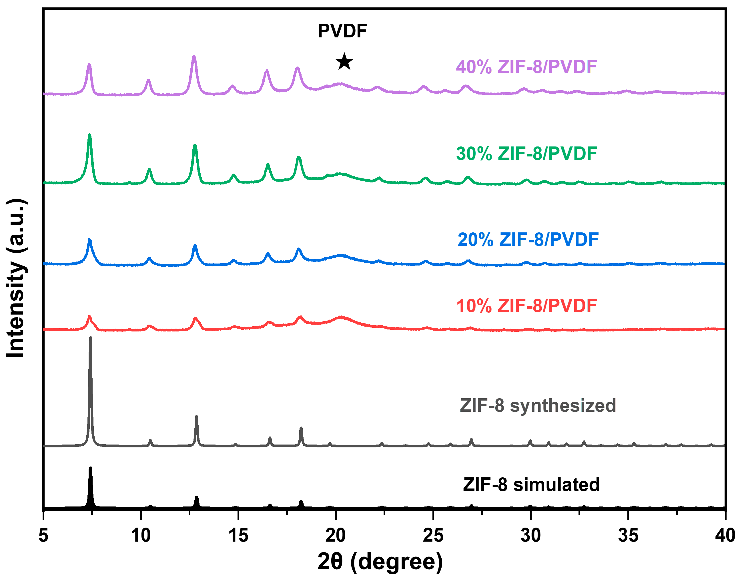
The XRD (Figure 1) shows that the ZIF-8 powder was successfully synthesized. The membranes were fabricated using a solution casting technique. The crystalline structure of MOF particles remains stable during membrane fabrication since the location of the diffraction peaks shows no shift. Furthermore, increasing the ZIF-8 content within the composite membrane resulted in a corresponding enhancement in the intensity of its characteristic diffraction peaks.
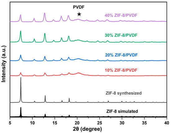
Figure 1.
XRD patterns of ZIF-8 particles and ZIF-8/PVDF membrane.
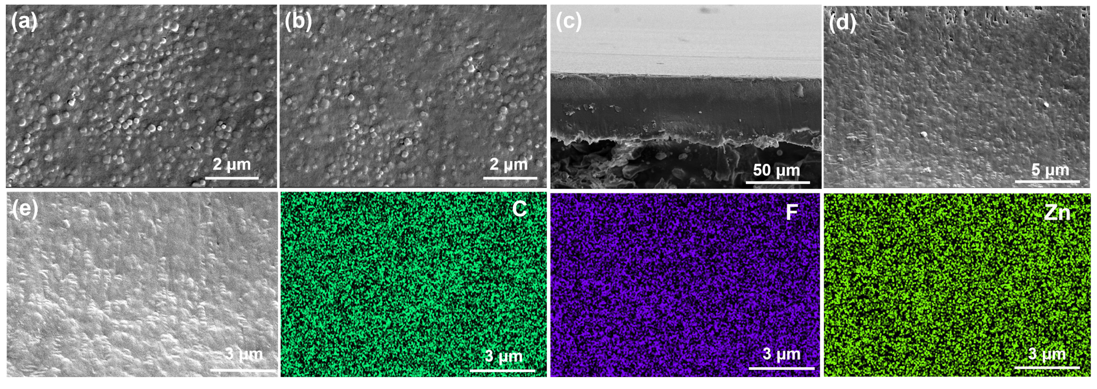
The surface and cross-sectional morphology of the membranes were examined using SEM (Figure 2). All the membranes with varying doping contents exhibit smooth, crack-free surfaces (Figure S1). Compared to the front side, the back surface of the 30% ZIF-8/PVDF exhibits a more uniform texture (Figure 2a,b). Both surfaces appear continuous and defect-free. AFM further confirms the smooth and dense microstructure of the membrane surface (Figure S2). The cross-section image reveals a compact structure with MOF particles densely embedded in the PVDF matrix, yielding a membrane thickness of approximately 50 μm (Figure 2c,d). The EDS confirms the homogeneous dispersion of ZIF-8 and PVDF throughout the material (Figure 2e). Additionally, the membrane is flexible (Figure S3), which is needed for their application in NARFB.

Figure 2.
SEM images of the 30% ZIF-8/PVDF membrane: (a,b) surface, (c,d) cross-section, and (e) cross-section elemental mapping.
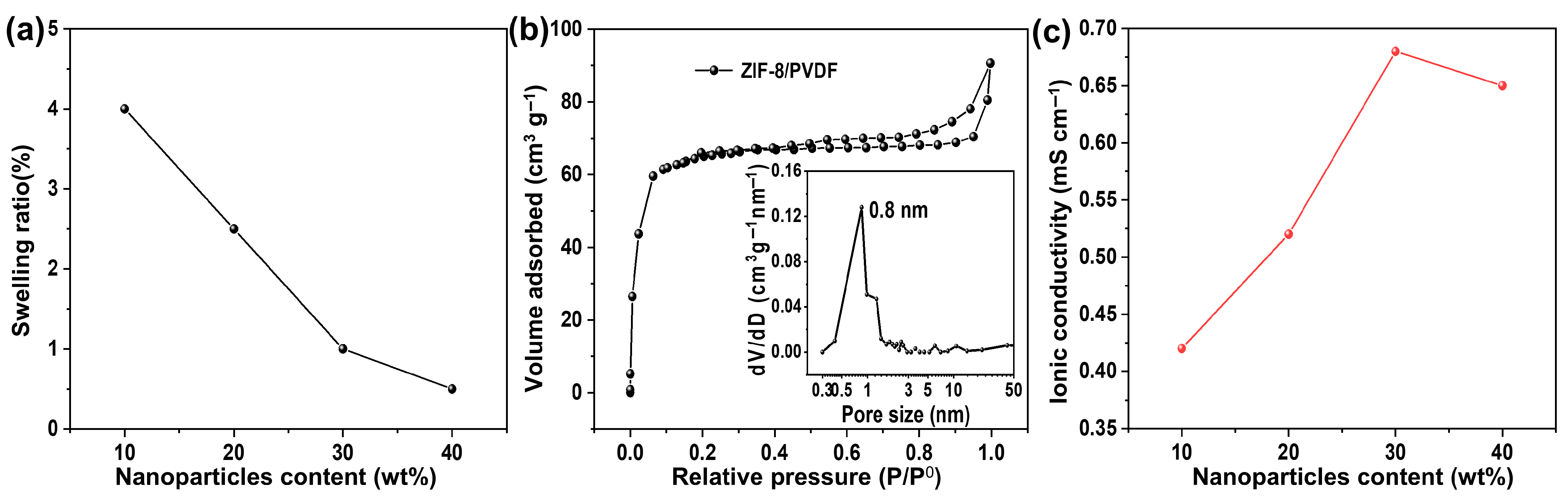
Elevated membrane swelling can exacerbate the crossover of redox-active species, compromising cell performance. The rigid framework of ZIF-8 particles effectively mitigates this swelling in the acetonitrile composite membrane in acetonitrile [26]. Consequently, the swelling ratio of the composite membranes decreases progressively with increasing MOF particle loading (Figure 3a), which is critical for enhancing the long-term dimensional and cycling stability.
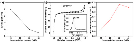
Figure 3.
(a) Swelling ratio of ZIF-8/PVDF composite membrane. (b) Nitrogen sorption isothermal curve of the 30% ZIF-8/PVDF membrane. Inset is the pore size distribution based on the NLDFT model. (c) Ionic conductivity of ZIF-8/PVDF composite membrane.
The pore properties of the ZIF-8/PVDF composite membrane were examined by N2 sorption (Figure 3b), and the obtained isotherm exhibits a combination of Type I and Type IV features, suggesting the simultaneous presence of micropores and mesopores. The pore size distribution, obtained from the NLDFT model, exhibits a prominent peak near 0.8 nm, which corresponds to the characteristic pore size of the ZIF-8 framework, along with a smaller fraction of mesopores. Given that the pore size of ZIF-8 (~0.8 nm) is intermediate between the diameters of the supporting electrolyte materials (TEA+ (0.52 nm) and TFSI− (0.54 nm) [27]) and the active materials (Fc1N112+ (~1 nm) and NI•− (~1.4 nm) (Figure S4) [28]), the framework facilitates the transport of small supporting ions while effectively hindering the transport of larger redox-active species. This size-exclusion effect is expected to reduce active material crossover, thereby contributing to enhanced cell performance.
The ionic conductivity of the membrane was evaluated by EIS (Figure S5). The intercept of the EIS curves with the X-axis at high frequency is the ohmic resistance, which is dominated by the resistance of the membrane. The ohmic resistance decreases with the content of ZIF-8 until 30% and then increases slightly with further increased content of ZIF-8. The resultant ionic conductivity is shown in Figure 3c. Incorporating ZIF-8 into the membrane enhances the number of available pathways for ion migration. The number of conductive paths in the membrane increases with MOF content; however, at higher content (e.g., >30%), the MOF particles may agglomerate and form large clusters, which hinders the transportation of the supporting electrolyte.
The selective transport of ions is a key criterion in evaluating membrane performance. Crossover of redox-active species can accelerate self-discharge and trigger undesirable parasitic reactions [29]. To investigate ion permeability, an H-type diffusion cell was employed to measure the transport of the supporting electrolyte (TEATFSI) and the redox-active species (Fc1N112-TFSI and NI-TFSI). Based on calibration curves (Figure S6), the concentration profiles over time were determined, and the corresponding diffusion behaviors of each species were plotted at various time points (Figure 4a–c). All the examined membranes displayed higher permeability for the supporting ions compared to the redox-active species. Compared with Daramic-250, the composite membranes show a smaller permeation rate. Furthermore, the decrease in the permeation rate of the active substance is more significant compared to that of the TEATFSI. The permeation of supporting electrolyte and the active species increases with the content of ZIF-8 until 30% and then decreases. The selectivity is quantified by calculating the ratio between the diffusion slopes of TEATFSI and the redox-active species. Relative to the commercial Daramic-250 membrane, the ZIF-8/PVDF composite membranes demonstrate markedly enhanced ion selectivity. The 30% ZIF-8/PVDF membrane shows the highest selectivity of TEATFSI/Fc1N112+ and TEATFSI/NI•− (20.5 and 23.4, respectively), 8.5 times that of the commercially available Daramic-250 membrane (2.4 and 2.9, respectively) (Figure 4d). The excellent ion selectivity of the 30% ZIF-8/PVDF composite membrane is mainly attributed to the size-sieving effect of MOFs within the membranes, as well as the dense microstructure obtained by the solution casting method. Based on the results above, the composite membrane 30% ZIF-8/PVDF shows the best performance, which is selected for further study.
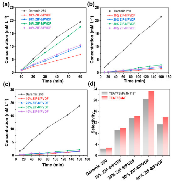
Figure 4.
Diffusion profiles of Daramic-250 and composite membranes with different ZIF-8 contents: (a) TEATFSI, (b) Fc1N112-TFSI, and (c) NI-TFSI. (d) Selectivity of different membranes.
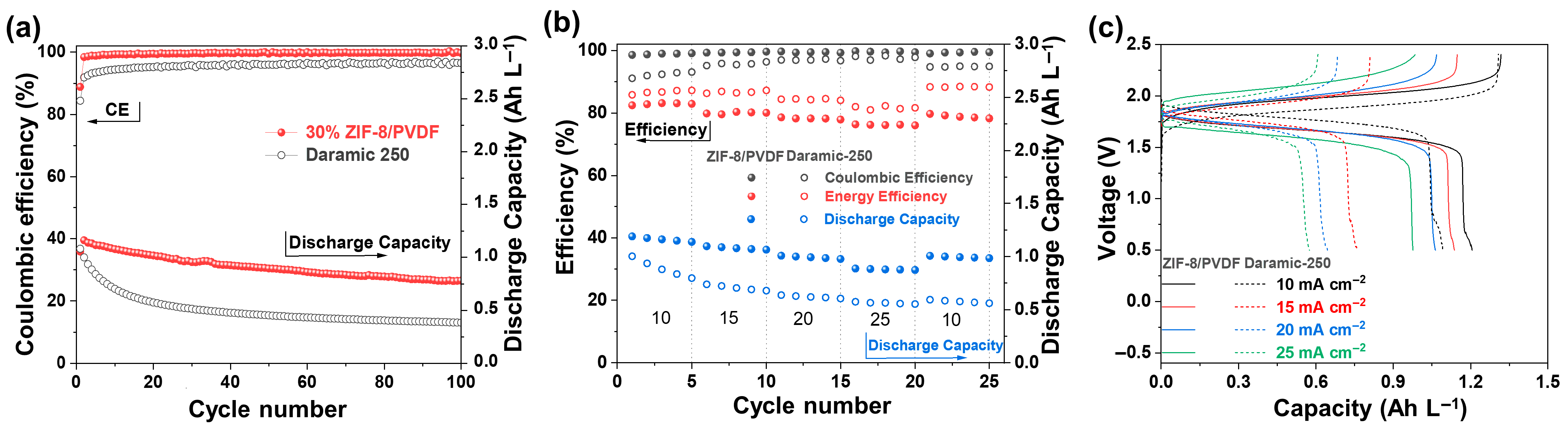
The anolyte and catholyte electrolytes exhibit good reversibility according to the CV test (Figure S7). The oxidation and reduction peak currents are nearly symmetric, further indicating that the redox reactions are electrochemically stable. The single cells based on Daramic-250 and 30% ZIF-8/PVDF membranes were assembled with 0.05 M Fc1N112-TFSI in 1 M TEATFSI/MeCN and 0.05 M NI-TFSI in 1 M TEATFSI/MeCN as catholyte and anolyte, respectively. The assembled cells maintain stable performance over 100 charge/discharge cycles under a current density of 10 mA cm−2 (Figure 5a). However, the capacity of the single cell based on Dramic-250 membrane exhibits an exponential decay from the 2nd to the 20th cycle. After 100 cycles, the discharge capacity decreases to only 0.35 Ah L−1. In contrast, the cell based on the 30% ZIF-8/PVDF membrane exhibits stable cycling behavior. It delivers an average discharge capacity of 0.92 Ah L−1, maintains a high Coulombic efficiency (CE) of 99.2%, and retains 74% of its initial capacity after 100 cycles.
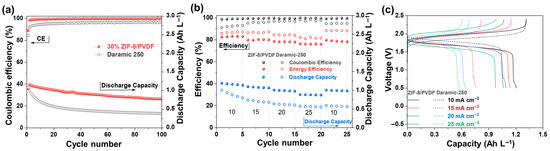
Figure 5.
(a) Long-term cycling performance of the batteries assembled with 30% ZIF-8/PVDF and Daramic-250 membranes at 10 mA cm−2. (b) Rate performance testing of batteries using 30% ZIF-8/PVDF and Daramic-250 membranes at different current densities. (c) Charge/discharge voltage-capacity curves under corresponding current density.
Superior rate performance plays a critical role in enabling rapid charge and discharge processes for high-efficiency energy storage applications. The 30% ZIF-8/PVDF membrane shows excellent rate capability from 10 to 25 mA cm−2 (Figure 5b). The capacity remains almost constant across all current densities, indicating good stability of the system. The average discharge capacities are 1.2, 1.1, 1.0, and 0.89 Ah L−1 at 10, 15, 20, and 25 mA cm−2, respectively. In comparison, cells assembled with the Daramic-250 membrane exhibit seriously lower average discharge capacities of only 0.89, 0.71, 0.62, and 0.56 Ah L−1 (Figure 5c). The 30% ZIF-8/PVDF membrane maintains CE values higher than 98% at all the current densities studied. The performance of the present battery is outstanding among the reported ones (Table S1).
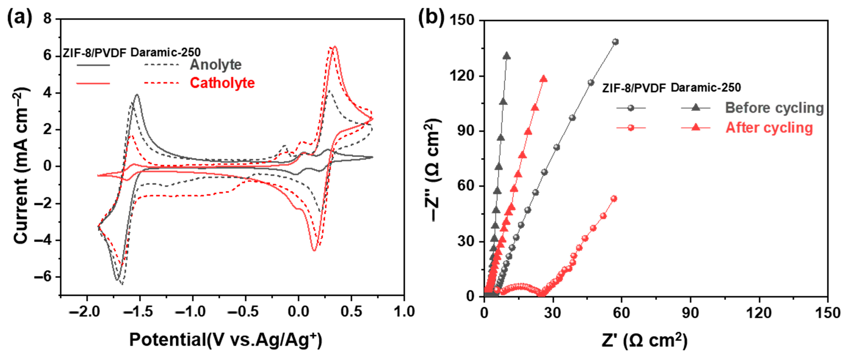
After 100 charge/discharge cycles, the CV curves of the anode and cathode electrolytes were recorded (Figure 6a). Compared with the Daramic-250 membrane, the 30% ZIF-8/PVDF membrane shows significantly suppressed crossover, which suggests the effectiveness of our strategy to design the membrane. The EIS of the cell was obtained both prior to and following cycling to evaluate changes in internal resistance (Figure 6b). The increase in ohmic resistance from 5.8 to 9.3 Ω·cm2 observed after cycling in the 30% ZIF-8/PVDF membrane is likely attributed to the surface accumulation of redox-active materials on both the membrane and electrode surfaces (Figure S8). In contrast, it increases from 4.8 to 6.8 Ω cm2 for the battery with the Daramic-250 membrane.
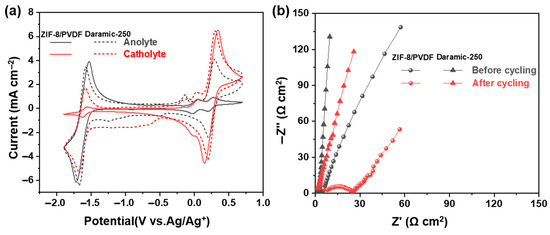
Figure 6.
(a) CV curves of cathode and anode electrolytes before and after cycling. (b) EIS of battery before and after cycling.
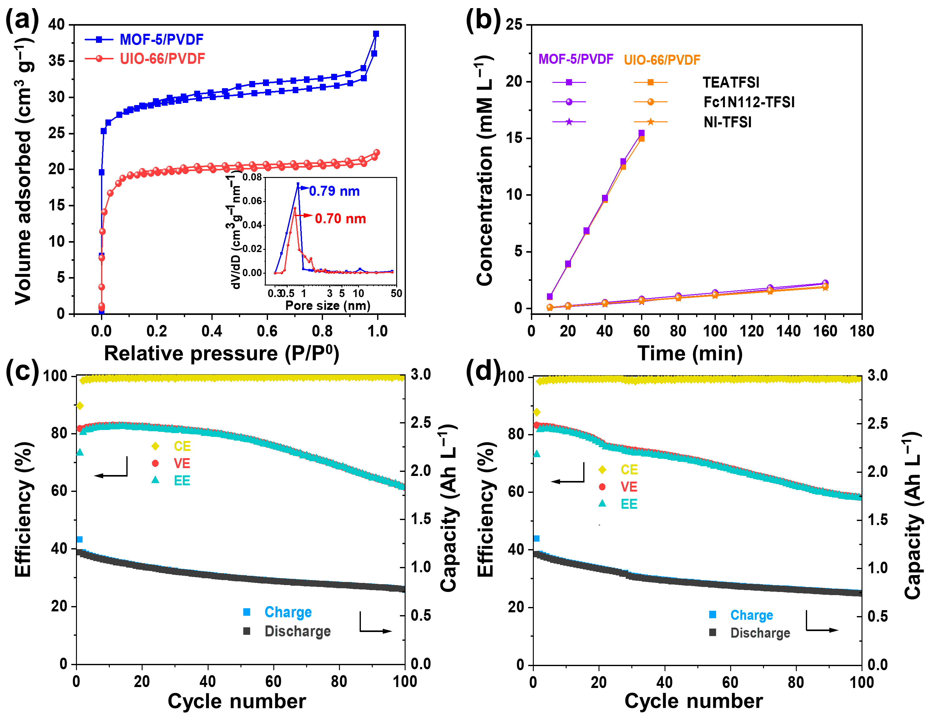
The results obviously show that by designing MOF with an appropriate pore size, the pore size is larger than the molecular size of the active materials but smaller than that of the supporting electrolyte, high-performance NARFB can be achieved. To show the versatility of the strategy, we designed another two composite porous membranes, MOF-5/PVDF and UIO-66/PVDF (Figure S9). Their structural pore size is 0.79 and 0.70 nm, respectively (Figure 7a). The permeability test reveals that both membranes significantly limit the migration of redox-active species, while still allowing sufficient passage of the supporting electrolyte ions (Figure 7b). The cation and anion selectivities of MOF-5/PVDF and UIO-66/PVDF are 20.6 and 23.8, and 20.9 and 24.1, respectively, much higher than that of the Daramic-250 membrane. The flow batteries based on both membranes were assembled, and their electrochemical cycling performance was evaluated at 10 mA cm−2. The batteries based on the MOF-5/PVDF and UIO-66/PVDF membranes maintain average CEs of 99.26% and 99.54% and discharge capacities of 0.88 and 0.91 Ah L−1 over 100 cycles, respectively (Figure 7c,d). These results suggest that the crossover issue is effectively alleviated. In fact, we tried several other MOF-based composite membranes. As long as the MOF materials are stable in the supporting electrolyte and active material systems, and the structural pore size is between the diameter of the redox-active materials and supporting electrolyte, the MOF-based composite membrane can suppress the crossover issue. It proves that our membrane design strategy is universal for the design of high-performance membranes for NARFB.
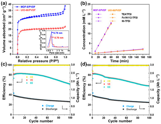
Figure 7.
(a) Adsorption–desorption isotherms of nitrogen along with the corresponding pore size distributions (shown in insets) for the MOF-5/PVDF and UIO-66/PVDF composite membranes. (b) Permeability profiles of TEATFSI, Fc1N112-TFSI, and NI-TFSI in MOF-5/PVDF and UIO-66/PVDF composite membranes. Cycling stability of the cells with (c) MOF-5/PVDF and (d) UIO-66/PVDF membranes at 10 mA cm−2.
4. Conclusions
In summary, flexible composite membranes (ZIF-8/PVDF) were fabricated using the solution casting method. Through effective pore design, the ZIF-8/PVDF membrane suppresses the crossover of active species. At 10 mA cm−2, the 30% ZIF-8/PVDF-based battery shows a high CE of 99.24% along with an average discharge capacity of 0.91 Ah L−1. The outstanding electrochemical performance is attributed to the ion-sieving functionality of the composite membranes. The design strategy of the ZIF-8/PVDF membrane, where the structural pore size of MOF is located between the molecular size of active materials and supporting electrolyte, can be extended to other MOF-based porous composite membranes for NARFB.
Supplementary Materials
The following supporting information can be downloaded at: https://www.mdpi.com/article/10.3390/pr13072127/s1, Figure S1: (a) 10% ZIF-8/PVDF membrane surface. (b) 20% ZIF-8/PVDF membrane surface. (c) 40% ZIF-8/PVDF membrane surface; Figure S2: AFM morphology of 30% ZIF-8/PVDF membrane; Figure S3: Photograph of the 30% ZIF-8/PVDF membrane; Figure S4: The ionic radius of NI•−.; Figure S5: EIS spectra of ZIF-8/PVDF composite membrane-based single cells; Figure S6: UV-Vis calibration curves of (a) FcN112-TFSI and (b) NI-TFSI. (c) Conductivity curve of TEATFSI; Figure S7: CV curves of (a) 0.01 M Fc1N112-TFSI/0.05 M TEATFSI and (b) 0.01 M NI-TFSI/0.05 M TEATFSI in the electrolyte (scan rate = 100 mV s−1); Figure S8: SEM and the corresponding EDS elemental mappings of the cycled 30% ZIF-8/PVDF membrane; Figure S9: (a) Crystal structure of MOF-5 and (b) UIO-66, (c) XRD patterns of MOF-5, MOF-5/PVDF membrane and (d) UIO-66 powder, UIO-66/PVDF membrane, (e) SEM of MOF-5/PVDF membrane and (f) UIO-66/PVDF membrane. (g) Photographs of MOF-5/PVDF and(h) UIO-66/PVDF membranes; Table S1: Performance comparison of the reported state-of-art membranes for NARFBs [4,8,13,14,20,30,31,32,33].
Author Contributions
Conceptualization, C.Z.; formal analysis, L.Z., D.X., and C.Z.; funding acquisition, Y.L.; investigation, L.Z. and D.X.; methodology, L.Z. and C.Z.; supervision, C.Z.; writing—original draft, L.Z.; writing—review and editing, C.Z. All authors have read and agreed to the published version of the manuscript.
Funding
This research was funded by National Natural Science Foundation of China (21636007).
Data Availability Statement
Data are contained within this article.
Conflicts of Interest
The authors declare that they have no known competing financial interests or personal relationships that could have appeared to influence the work reported in this paper.
References
- Yang, Z.; Zhang, J.; Kintner-Meyer, M.; Lu, X.; Choi, D.; Lemmon, J.P.; Liu, J. Electrochemical energy storage for green grid. Chem. Rev. 2011, 111, 3577–3613. [Google Scholar] [CrossRef] [PubMed]
- Ding, Y.; Zhang, C.; Zhang, L.; Zhou, Y.; Yu, G. Molecular engineering of organic electroactive materials for redox flow batteries. Chem. Soc. Rev. 2018, 47, 69–103. [Google Scholar] [CrossRef]
- Chen, H.; Cong, G.; Lu, Y.-C. Recent progress in organic redox flow batteries: Active materials, electrolytes and membranes. J. Energy Chem. 2018, 27, 1304–1325. [Google Scholar] [CrossRef]
- Bang, H.; Kim, D.; Hwang, S.; Won, J. Surface-modified porous membranes with electrospun Nafion/PVA fibres for non-aqueous redox flow battery. J. Membr. Sci. 2016, 514, 186–194. [Google Scholar] [CrossRef]
- Muthuraman, G.; Boyeol, L.M. Il-Shik, Na-β-alumina as a separator in the development of all-vanadium non-aqueous tubular redox flow batteries: An electrochemical and charging-discharging examination using a prototype tubular redox flow cell. J. Electrochem. Soc. 2018, 165, A1920–A1924. [Google Scholar] [CrossRef]
- Zhang, C.; Niu, Z.; Ding, Y.; Zhang, L.; Zhou, Y.; Guo, X.; Zhang, X.; Zhao, Y.; Yu, G. Highly concentrated phthalimide-based anolytes for organic redox flow batteries with enhanced reversibility. Chem 2018, 4, 2814–2825. [Google Scholar] [CrossRef]
- Takechi, K.; Kato, Y.; Hase, Y. A highly concentrated catholyte based on a solvate ionic liquid for rechargeable flow batteries. Adv. Mater. 2015, 27, 2501–2506. [Google Scholar] [CrossRef]
- Jia, C.; Pan, F.; Zhu, Y.; Huang, Q.; Lu, L.; Wang, Q. High-energy density nonaqueous all redox flow lithium battery enabled with a polymeric membrane. Sci. Adv. 2015, 1, e1500886. [Google Scholar] [CrossRef]
- Pan, F.; Yang, J.; Huang, Q.; Wang, X.; Huang, H.; Wang, Q. Redox targeting of Anatase TiO2 for redox flow lithium-ion batteries. Adv. Energy Mater. 2014, 4, 1400567. [Google Scholar] [CrossRef]
- Doris, S.; Ward, A.; Baskin, A.; Frischmann, P.; Gavvalapalli, N.; Chénard, E.; Sevov, C.; Prendergast, D.; Moore, J.; Helms, B. Macromolecular design strategies for preventing active-material crossover in non-aqueous all-organic redox-flow batteries. Angew. Chem. Int. Ed. Engl. 2017, 56, 1595–1599. [Google Scholar] [CrossRef]
- Shin, S.-H.; Kim, Y.; Yun, S.-H.; Maurya, S.; Moon, S.-H. Influence of membrane structure on the operating current densities of non-aqueous redox flow batteries: Organic-inorganic composite membranes based on a semi-interpenetrating polymer network. J. Power Sources 2015, 296, 245–254. [Google Scholar] [CrossRef]
- Lou, X.; Ye, J.; Xia, L.; Chang, S.; Zhao, X.; Wu, C.; Ding, M. Highly efficient and low cost SPEEK/TiO2 nanocomposite membrane for vanadium redox flow battery. J. Nanosci. Nanotechnol. 2019, 19, 2247–2252. [Google Scholar] [CrossRef]
- Liu, T.; Zhang, C.; Yuan, J.; Zhen, Y.; Li, Y. Two-dimensional vermiculite nanosheets-modified porous membrane for non-aqueous redox flow batteries. J. Power Sources 2021, 500, 229987. [Google Scholar] [CrossRef]
- Yuan, J.; Zhang, C.; Liu, T.; Zhen, Y.; Pan, Z.; Li, Y. Two-dimensional metal-organic framework nanosheets-modified porous separator for non-aqueous redox flow batteries. J. Membr. Sci. 2020, 612, 118463. [Google Scholar] [CrossRef]
- Zhou, X.; Xue, R.; Zhong, Y.; Zhang, Y.; Jiang, F. Asymmetric porous membranes with ultra-high ion selectivity for vanadium redox flow batteries. J. Membr. Sci. 2020, 595, 117614. [Google Scholar] [CrossRef]
- Zhao, M.; Wang, Y.; Ma, Q.; Huang, Y.; Zhang, X.; Ping, J.; Zhang, Z.; Lu, Q.; Yu, Y.; Xu, H.; et al. Ultrathin 2D metal-organic framework nanosheets. Adv. Mater. 2015, 27, 7372–7378. [Google Scholar] [CrossRef] [PubMed]
- Li, S.; Han, W.; An, Q.-F.; Yong, K.-T.; Yin, M.-J. Defect engineering of MOF-based membrane for gas separation. Adv. Funct. Mater. 2023, 33, 2303447. [Google Scholar] [CrossRef]
- Lee, G.; Yoo, D.; Ahmed, I.; Lee, H.; Jhung, S. Metal-organic frameworks composed of nitro groups: Preparation and applications in adsorption and catalysis. Chem. Eng. J. 2023, 451, 138538. [Google Scholar] [CrossRef]
- Lee, D.; Yu, X.; Sikma, R.; Li, M.; Cohen, S.; Cai, G.; Chen, Z. Holistic design consideration of metal-organic framework-based composite membranes for lithium-sulfur batteries. ACS Appl. Mater. Interfaces 2022, 14, 34742–34749. [Google Scholar] [CrossRef]
- Peng, S.; Zhang, L.; Zhang, C.; Ding, Y.; Guo, X.; He, G.; Yu, G. Gradient-distributed metal-organic framework-based porous membranes for nonaqueous redox flow batteries. Adv. Energy Mater. 2018, 8, 1802533. [Google Scholar] [CrossRef]
- Yuan, J.; Zhang, C.; Qiu, Q.; Pan, Z.-Z.; Fan, L.; Zhao, Y.; Li, Y. Highly selective metal-organic framework-based (MOF-5) separator for non-aqueous redox flow battery. Chem. Eng. J. 2022, 433, 133564. [Google Scholar] [CrossRef]
- Xu, D.; Zhang, C.; Li, Y. Molecular engineering the naphthalimide compounds as high-capacity anolyte for nonaqueous redox flow batteries. Chem. Eng. J. 2022, 439, 135766. [Google Scholar] [CrossRef]
- Kida, K.; Okita, M.; Fujita, K.; Tanaka, S.; Miyake, Y. Formation of high crystalline ZIF-8 in an aqueous solution. CrystEngComm 2013, 15, 1794–1801. [Google Scholar] [CrossRef]
- Zhao, Z.; Ma, X.; Li, Z.; Lin, Y. Synthesis, characterization and gas transport properties of MOF-5 membranes. J. Membr. Sci. 2011, 382, 82–90. [Google Scholar] [CrossRef]
- Kalaj, M.; Denny, M.; Bentz, K.; Palomba, J.; Cohen, S. Nylon-MOF composites through postsynthetic polymerization. Angew. Chem. Int. Ed. 2019, 58, 2336–2340. [Google Scholar] [CrossRef] [PubMed]
- Xin, L.; Zhang, D.; Qu, K.; Lu, Y.; Wang, Y.; Huang, K.; Wang, Z.; Jin, W.; Xu, Z. Zr-MOF-enabled controllable ion sieving and proton conductivity in flow battery membrane. Adv. Funct. Mater. 2021, 31, 2104629. [Google Scholar] [CrossRef]
- Ue, M. Mobility and ionic association of lithium and quaternary ammonium salts in propylene carbonate and γ-butyrolactone. J. Electrochem.Soc. 1994, 141, 3336. [Google Scholar] [CrossRef]
- Han, K.; Rajput, N.; Wei, X.; Wang, W.; Hu, J.; Persson, K.; Mueller, K. Diffusional motion of redox centers in carbonate electrolytes. J. Chem. Phys. 2014, 141, 104509. [Google Scholar] [CrossRef]
- Yuan, J.; Shi, X.; Qiu, Q.; Yao, P.; Xia, Y.; Zhao, Y.; Li, Y. Ion selective bifunctional metal-organic framework-based membrane for lithium metal-based nonaqueous redox flow battery. ACS Appl. Energy Mater. 2022, 6, 416–423. [Google Scholar] [CrossRef]
- Kim, D.; Song, J.; Won, J. Structural effects of anion exchange composite membranes in non-aqueous redox flow batteries. J. Membr. Sci. 2018, 564, 523–531. [Google Scholar] [CrossRef]
- Jung, J.; Won, J.; Hwang, S. Highly selective composite membranes using ladder-like structured polysilsesquioxane for a non-aqueous redox flow battery. J. Membr. Sci. 2020, 595, 117520. [Google Scholar] [CrossRef]
- Akhmetov, N.; Waris, Z.; Ryazantsev, S.; Lipovskikh, S.; Gvozdik, N.; Pogosova, M.; Stevenson, K. Towards durable Li-hybrid flow batteries: Composite membrane development, cell performance, and perspective. J. Mater. Chem. A 2023, 11, 19656–19668. [Google Scholar] [CrossRef]
- Kwon, G.; Lee, S.; Hwang, J.; Shim, H.-S.; Lee, B.; Lee, M.H.; Ko, Y.; Jung, S.-K.; Ku, K.; Hong, J.; et al. Multi-redox molecule for high-energy redox flow batteries. Joule 2018, 2, 1771–1782. [Google Scholar] [CrossRef]

Disclaimer/Publisher’s Note: The statements, opinions and data contained in all publications are solely those of the individual author(s) and contributor(s) and not of MDPI and/or the editor(s). MDPI and/or the editor(s) disclaim responsibility for any injury to people or property resulting from any ideas, methods, instructions or products referred to in the content. |
© 2025 by the authors. Licensee MDPI, Basel, Switzerland. This article is an open access article distributed under the terms and conditions of the Creative Commons Attribution (CC BY) license (https://creativecommons.org/licenses/by/4.0/).