1. Introduction
Offshore wind farming is a rapidly developing practice, proving to be one of the most viable strategies in the global push towards energy decarbonization. The Global Wind Energy Council’s 2023 global offshore wind report [
1] indicates that between 2023 and 2032, over 380 GW of offshore wind energy is expected to be added to the grid, yielding a total offshore wind capacity of 447 GW by the end of 2032.
Offshore wind turbines operate using the same principles as common onshore wind turbines. Wind-driven lift and drag forces are exerted on the blades of the turbine, which cause the rotor to spin. A gearbox increases the rotation speed, and a generator converts the energy to electricity in the form of an alternating current, which is then distributed through substations to the grid (and subsequently to houses) [
2].
Regular onshore wind turbines are abundant in the Southern Ontario Lake Huron area [
3]. Increased wind speeds and a lack of physical interference mean that offshore wind turbines are likely to be more efficient when properly implemented. Still, the design and implementation of offshore wind turbines present unique challenges.
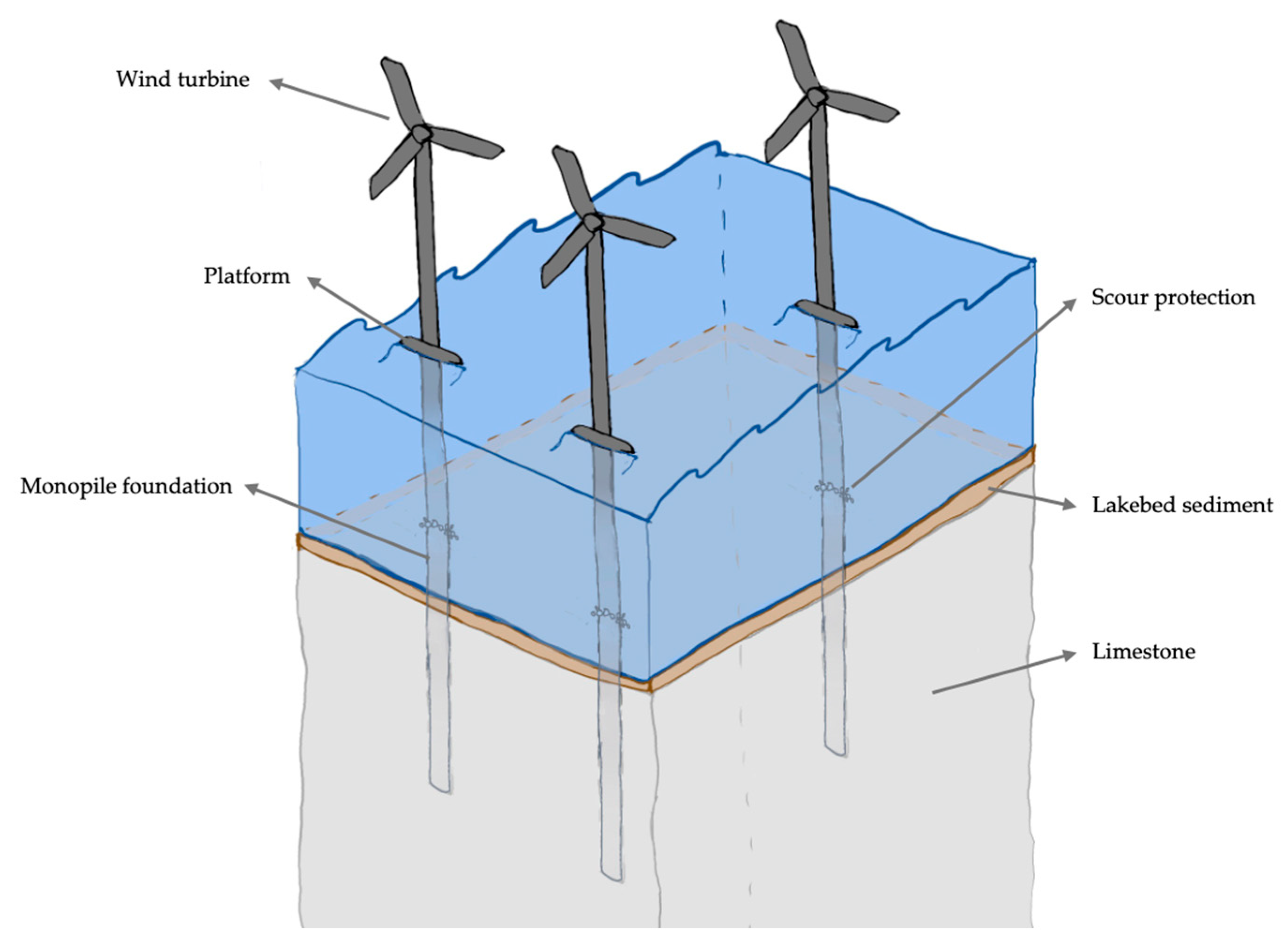
Figure 1 depicts a hypothetical offshore wind farm in Lake Huron.
While the upper component of an offshore wind turbine resembles a regular onshore wind turbine, offshore wind turbine foundations are generally more technically advanced and require innovative solutions, given the unique nature of underwater structure stability. Offshore wind turbine foundations fall into two categories: floating and fixed. Floating wind turbines sit on large, buoyant rafts with cables anchoring the buoyant platform to the bedrock [
4]. Floating wind turbines are practical for offshore wind turbines installed at depths greater than 60 m, where full fixed foundations would be economically unfeasible [
4].
Fixed foundations assume different forms and vary in material and composition based on depth and bedrock geology. The design of fixed foundations involves the assessment of various load cases, which are well-researched in ocean environments but require significant research in the unique constraints of the Great Lakes context [
5]. Gravity and monopile foundations are commonly seen at shallow depths, around 15 to 40 m below the seabed, since their implementation and cost are significantly lower than more technically complex solutions, like tripod foundations or foundations with suction buckets [
4]. Floating foundations are common at depths of 80 m or below the seabed [
4].
Typical offshore wind farms involve multiple wind turbines that connect to an offshore substation. Energy is then distributed to an onshore system and allocated across the grid [
6]. The first offshore wind farm was constructed in 1991, where 11 wind turbines were erected off the coast of a Danish island. Vindeby Wind Farm powered approximately 2200 households annually before its decommissioning in 2001 [
7]. The farm consisted of onshore wind turbines built on simple concrete foundations in shallow water [
7].
In 2019, Ørsted and Jupiter Offshore Wind Limited began operations at the Hornsea Wind Farm in the North Sea [
8]. The farm comprises 174 wind turbines and has a combined total capacity of 1.2 GW, capable of powering over one million homes in the United Kingdom [
8]. Each turbine has 75-meter-long blades, and one rotation can power a home for over 24 h [
8].
The turbines are on monopile foundations, which generally involve steel tubes drilled or driven into the ground [
4]. The embedment and diameter of the tube depend largely on the geologic conditions at the seabed where the turbines are being installed.
The Borkum Riffgrund 1 wind farm was the first offshore wind farm to implement a suction bucket jacket foundation [
9]. Off the coast of Northern Germany, the wind farm has 78 wind turbines, each of which generates approximately 4 MW of energy [
9]. The farm became operational in 2014, and only one turbine was built on a suction bucket jacket foundation to test the feasibility of a suction-based system [
9]. The system involves three caissons, or suction buckets, at the end of the jacket framework structure. The caissons were placed on the seabed, and water was pumped out to create a pressure differential [
9]. The heightened pressure outside of the caissons forces the partial embedment of the caisson into the seabed, and this added friction enhances the system’s stability [
9].
The state-of-the-art in offshore wind farming is regularly developing as a result of constant experimentation and empirical research. Horns Rev 1 Wind Farm, installed in 2002 in shallow water off the coast of Denmark, used scour protection to mediate the risk of scour from large waves and tidal currents [
10]. Scour protection often involves placing large stones or rock bags at the base of a submerged pile or footing to protect the surrounding sediment or rock from erosion [
10].
In 2005, three years after the installation of the Horns Rev 1 Wind Farm, the scour protection around the exposed base of the monopiles sank by up to 1.5 m [
10]. Additional scour protection was added on top of the existing stone to repair the system [
10].
Horns Rev 1 provides valuable insights into the impact of the marine environment on the design of offshore wind turbines. Neilson et al. [
10] concluded that the removal of sediment below the scour protection is a viable cause for the sinking, as is the strength of the current combined with the intensity of the waves experienced at the shallow site of the wind farm. Both possibilities highlight the importance of understanding the environmental conditions at the site of an offshore wind farm to optimize design performance.
Like any structure, there are important geotechnical considerations in the foundation design of offshore wind turbines. Submerged foundation design hosts unique challenges associated with buoyant forces, bedrock pore pressure, and the dissolution of carbonate-rich bedrock, among other geologic concerns.
This report and its supporting research intend to assess the geomechanical feasibility of implementing offshore wind turbines in Lake Huron under simplified wave loading. Namely, the potential for the lakebed bedrock in Lake Huron to support foundations for offshore wind turbines will be analyzed.
Other components of an offshore wind farm, including offshore substations and power distribution systems, will not be analyzed in this report. Environmental and biological impacts, while relevant to the assessment of the viability of Lake Huron for offshore wind farming, will not be considered in the scope of this research. Renewable energy policy and existing energy infrastructure are highly influential on the development and implementation of offshore wind farms and should be considered in future studies of the Great Lakes area [
11].
This research aims to provide a baseline for the relevant geomechanical considerations needed to support the holistic design of an offshore wind farm in Lake Huron. The findings of this research on wind turbine design and efficacy should be expanded comprehensively to properly design an offshore wind farm that reasonably considers all relevant facets of energy systems design.
2. Geologic Setting
The relevant geologic history of the Great Lakes region begins in the Precambrian, around 3600 Ma. During the Archean eon, volcanic and intrusive rocks formed in the area now known as the Canadian Shield [
12]. This bedrock underwent 150 million years of erosion and metamorphosis until the beginning of the Proterozoic eon, when Paleoproterozoic intrusive volcanic rocks were formed, and sedimentary rocks were deposited over the Archean bedrock [
13].
The Precambrian was followed by the Paleozoic (around 541 Ma), during which ancient seas encroached and retreated repeatedly over the existing bedrock. This led to the deposition of sand, shale, limestone and other sediment along the sea shorelines in the Michigan basin [
12].
As they exist today, the Great Lakes were largely shaped by several glaciation episodes during the Quaternary period, 2.6 Ma. Glaciations shaped the Great Lake basins through preferential scouring, which was characterized by the heavy deformation of weaker, less-competent bedrock [
12]. Glacial erosion gradually altered the surficial geology of the Great Lakes area, as the glaciers would transport and deposit clasts along their flow path [
12].
The most recent glacial episode, the Wisconsinan, experienced maximum glacial cover approximately 20,000 years ago [
14]. During the Wisconsinan advance, many deposits of the loosely consolidated debris transported from previous glaciations were eroded or captured and transported, exposing the underlying bedrock in certain parts of the Great Lakes region [
12].
The Wisconsinan glacier retreated around 10,000 years ago [
12] and left a polished bedrock surface along the shoreline of Lake Huron [
14]. The Lake Huron topography is further enhanced by isostatic rebound, the process during which the Earth’s crust gradually rebounds after the unloading of the glaciers [
15]. Isostatic rebound causing minor changes in the orientation of the Great Lakes and their shorelines is only one of many impacts on the Great Lakes area landscape as a result of the glacial episodes.
With any geotechnical engineering project, subsurface uncertainty can be a challenge in developing adequate design parameters. The added constraint of underwater construction presents challenges in completing subsurface exploration or in situ geomechanical testing. As such, a comprehensive understanding of the geologic history and formation of the area is important in selecting design constraints.
The Lake Huron bedrock geology hosts limestone and dolomite, among other sedimentary rocks, which are prone to dissolution in water and can lead to the development of karst formations [
16]. In situ, karst formations assume the form of cracks in the seafloor and sinkholes, providing poor conditions for subsurface structure foundations.
Geophysical analyses show that the groundwater composition in these karst formation sinkholes varies significantly from the composition of the freshwater in the lake [
16]. The water has a high conductivity, likely due to high concentrations of carbonate and sulphate ions from the dissolution of the carbonate-rich bedrock.
The geologic conditions in Lake Huron may mandate the complex design of offshore wind turbine foundations. Understanding the Precambrian and Paleozoic origins of the bedrock will help develop a geologic profile of the lakebed, but challenges associated with carbonate-rich rock and moderate-depth marine foundations must be considered in the characterization of the site.
In the area of study, rock is largely from the Silurian and Devonian periods. Limestone, dolostone, and shale largely comprise the seabed in this area and align with the geologic history of the Lake Huron area [
12].
Ideally, laboratory testing would be conducted on samples directly from the site. For the sake of this analysis, conservative geomechanical parameters will be adopted based on previous geotechnical testing on samples from similar geographies and lithologies. The Amherstberg formation, comprising middle-aged Devonian limestones and dolostones, is prominent in the Lake Huron area. A study by the Nuclear Waste Management Organization and AECOM [
17] analyzes the geomechanical properties of the bedrock formations around the Bruce Nuclear site, which is similar in latitude to the proposed location for the offshore wind farm.
The Devonian Detroit River Group is the surficial unit in the area of concern. The study provides geomechanical data for the limestone and dolomite units in the Amherstburg formation, which will be adopted for the analysis in this study [
17].
Uniaxial compression tests on the Amherstburg dolomite and limestone were performed, resulting in unconfined compressive strengths (UCS) of 63 and 74 MPa, respectively [
17]. A site literature review generally indicates that the limestone is more prominent in the unit [
12,
13], so a conservative UCS of 70 MPa was assumed for the unit. For the unit weight, a relatively conservative value of 22.0 kN/m
3 was assumed based on industry research [
18] as well as the consideration that the material is submerged, and the dissolution of carbonate minerals (which can lead to karst formations) generally decreases unit weight. Since exploration is limited, conservative parameters should be implemented.
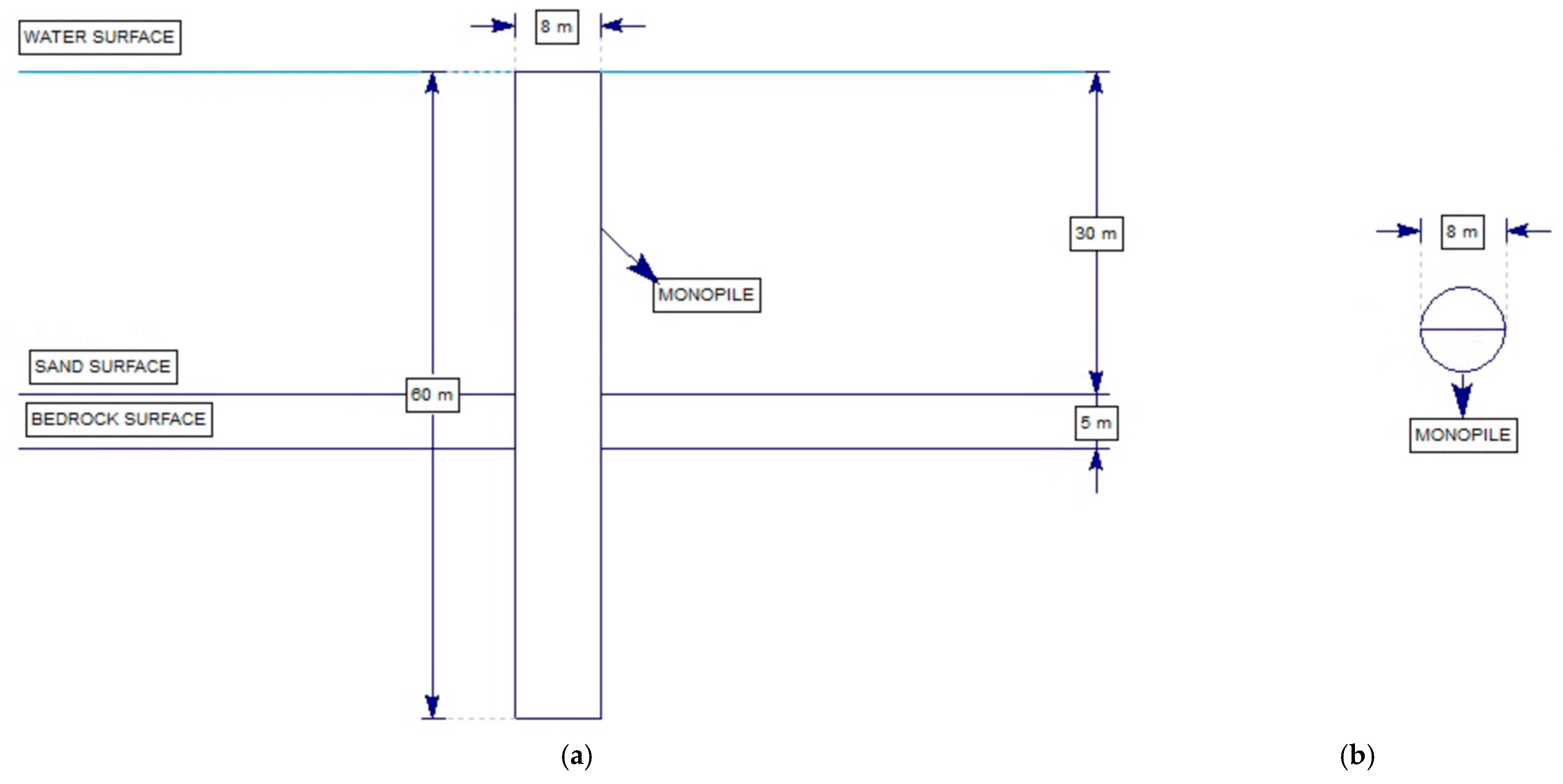
A loose, 5 m layer of sand with a unit weight of 20 kN/m3 and a friction angle of 30° was considered overlying the bedrock, since erosion of the material over time is likely to have led to sediment buildup along the seabed.
Since bedrock is shallow, there may be some concern about the successful driving of monopiles. The bedrock at the site is vuggy, and while drilling may be required before pile implementation, the overall benefits of a well-researched, implemented and studied system like monopile foundations outweigh the associated higher costs. Industry experts are investigating systems to make monopile driving into bedrock easier [
19], and there will likely be new strategies and technologies for driving monopiles into bedrock by the time the preliminary design and permitting of an offshore wind farm in Lake Huron are completed. Still, this can be seen as a major constraint. While implementing offshore wind farms for the first time in the Great Lakes would ideally involve the prevailing foundation design system, other options may be investigated in future studies. For the sake of this analysis, monopiles will be assessed in bedrock for other concerns like deflection, settlement, and distortion.
The required depth to the seabed for offshore wind turbines varies by foundation type. While monopile-supported turbines are generally only sufficient at depths of 30–40 m, foundations with suction-based anchoring systems can reasonably reach depths of 70+ m [
4]. Industry research shows the prevalence of pile-based foundations, likely due to their ease from both an economic and constructability standpoint. As such, monopile foundations are a favorable design for the early implementation of offshore wind turbines in the Lake Huron area.
As a first attempt at offshore wind farming in Lake Huron, a simple and familiar system is likely to have the most success. The simplicity of monopile foundations means that they can be implemented at shallow lake levels, minimizing construction costs and hurdles. While offshore wind farms possess a strong potential for the Great Lakes area power supply, their gradual implementation (beginning with simplistic and non-strenuous designs) is ideal.
Realistically, an inaugural wind farm in Lake Huron will not rival the scale of offshore wind farming operations in the North Sea or other geographies with advanced wind farming infrastructure. Cultural differences in the reception of offshore wind farming aside, conservative budget and constructability factors will impact the magnitude of a Great Lakes offshore wind farm. Since monopile foundations have been established as a feasible foundation system, given their widespread popularity in offshore wind farming (and early development as the foundation system for the first offshore wind farm), costs will be relatively low, and construction will be moderately fast.
Minimizing the distance from the shoreline to major operations is ideal for ease of wind farm maintenance. Because monopile foundations are also generally better-suited to shallower depths [
4], a depth to the seabed of around 30 to 40 m would be ideal for the wind farm location.
Figure 2 [
20] shows the bathymetry of Lake Huron, which is effectively the depth to the seabed from the standard water level.
The wind speed above the selected geography should also be considered. Kinetic wind energy output from a wind turbine is an exponential function of the wind speed, and the optimal wind farm location will host high wind speeds near the surface. Wind speeds in Lake Huron are highest near the Harrisville Basin, reaching 9.75 m/s at 160 m above the lake surface level [
21].
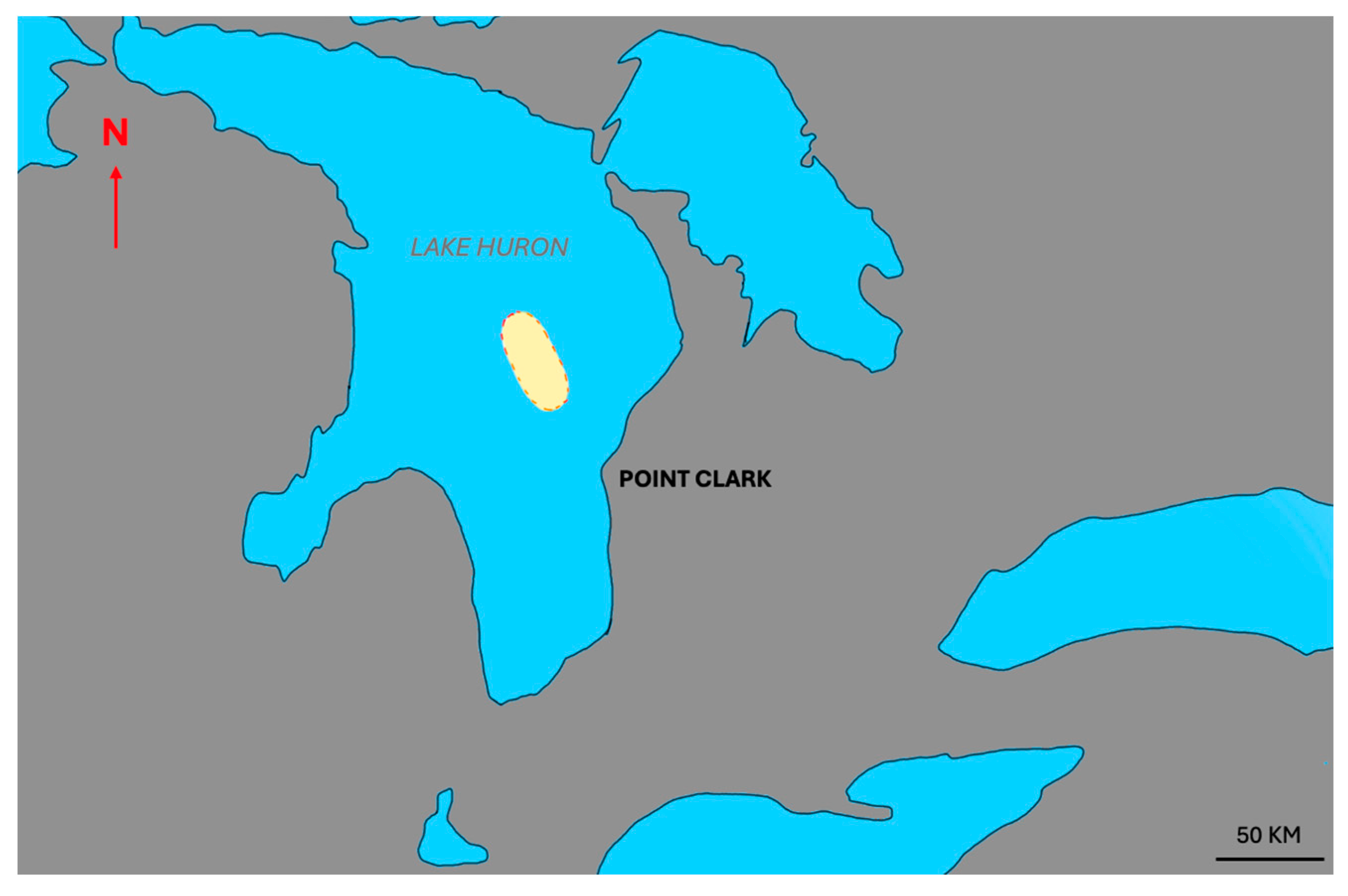
When considering lake bathymetry and wind speeds, a practical area for an offshore wind farm in Lake Huron is off the eastern coast of the lake in southwestern Ontario, approximately 40 km northwest of Point Clark, Ontario. Here, the depth below the lake level averages near 30 m [
20] and wind speeds exceed 9.75 m/s [
21].
Figure 3 highlights the identified location of the study for an offshore wind farm in Lake Huron.
3. Model Development
RSPile was used for model development for laterally loaded piles. The main parameter to take from the soil is the reaction modulus. It is defined as the resistance from the soil at a point along the depth of the pile divided by the horizontal deflection of the pile at that point. RSPile defines this reaction modulus (E
py) using the secant of the p–y curve [
22].
Equations (1)–(4) are the governing differential equations for the implementation of the p–y method [
22].
where:
y = lateral deflection of the pile;
= bending stiffness of pile;
= axial load on pile head;
= soil reaction modulus based on
= distributed load down some length of the pile;
= shear in the pile;
= bending moment of the pile;
= slope of the curve defined by the axis of the pile [
23].
The recommended curve for strong rock was developed based on field tests on instrumented drilled shafts in vuggy limestone [
22].
Figure 4 shows the p–y curve in the manual [
23].
On sand below water, the p–y curve must consider the friction angle and soil unit weight, and for the soil unit weight, a k
py input is also required, which defines the initial straight-line portion of the p–y curve. RSPile provides recommended K
py values for submerged sand of various densities based on the analysis of full-scale experiments with instrumented piles [
22]. RSPile calculates the soil resistance, p
k, and pile deflection, y
k, from p
m, p
u, y
m, and y
u [
22].
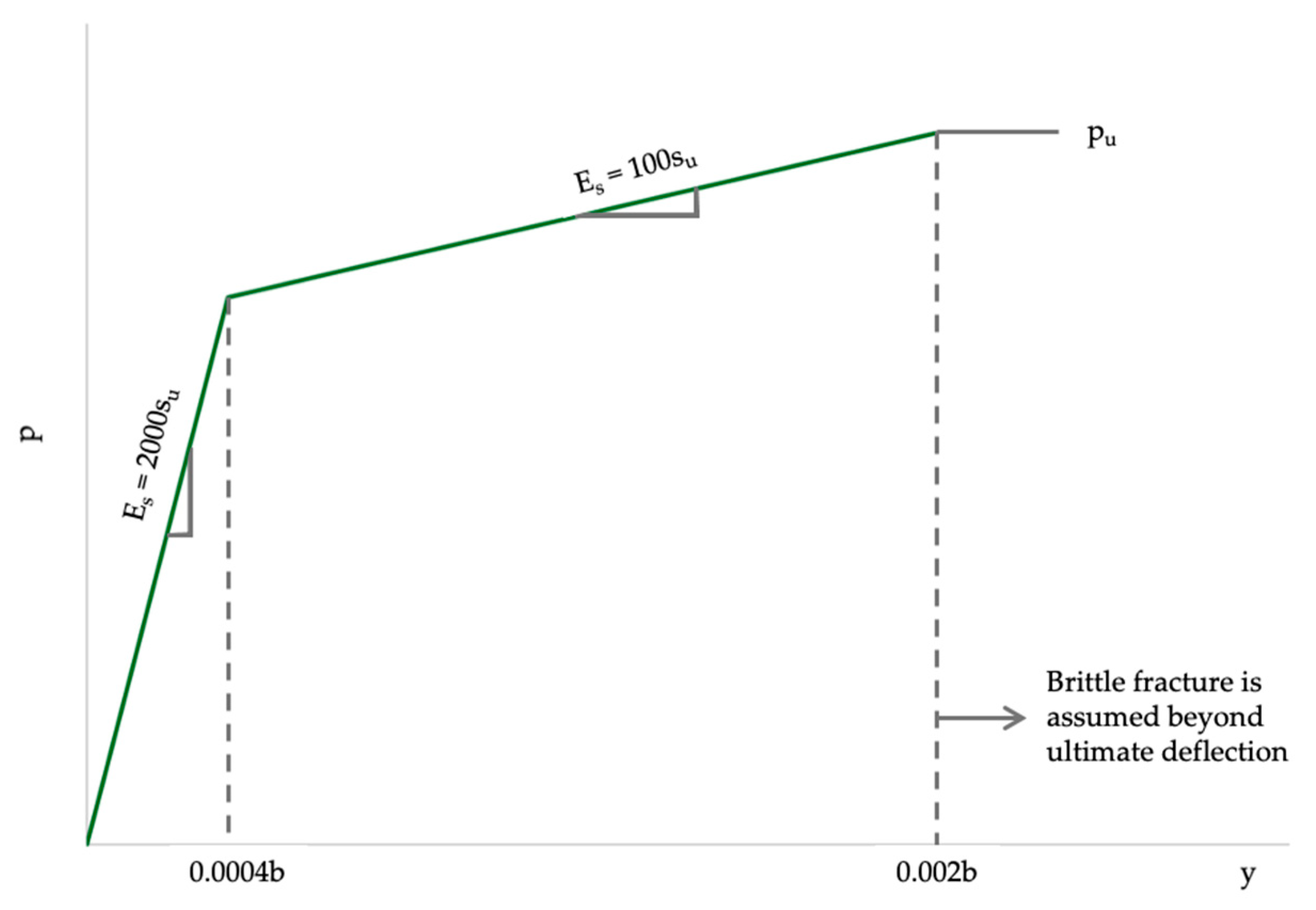
Figure 5 shows the p–y curve for sand [
22].
For the sand, the soil resistance, p
k, and pile deflection, p
y, are calculated from p
m, p
u, y
m, and y
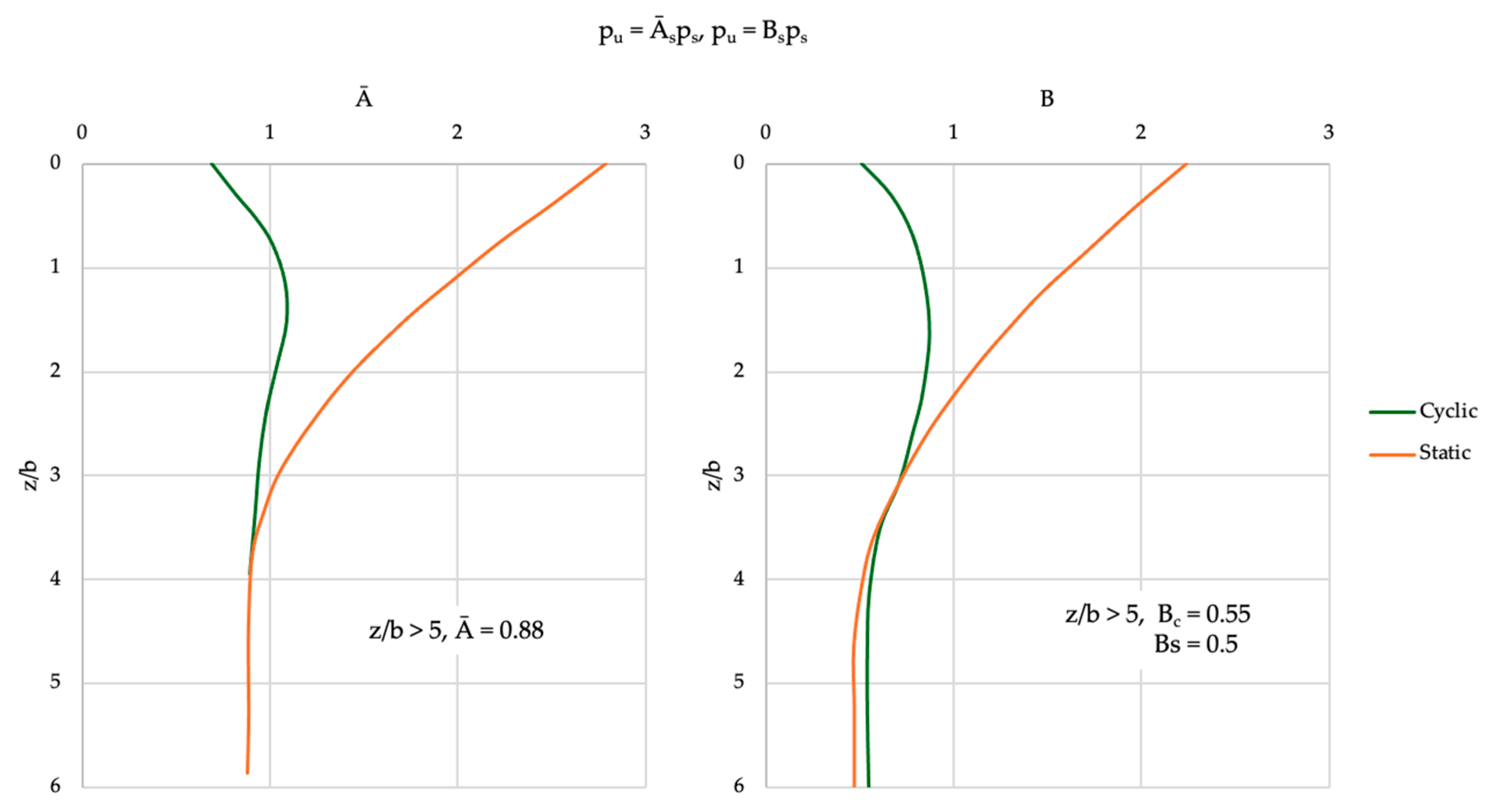
u. p
u and p
m are calculated using the smaller value given by p
s from Equations (5) and (6), and multiplied by coefficients A and B in
Figure 6 [
23].
RSPile involves finite element analysis. The RS3 finite element beam engine is employed in RSPile [
22]. The piles are formulated as line components [
22]. The beams are formulated on the assumption of Timoshenko beams, which considers shear stresses on their cross-sectional area [
22].
In this research, a virtual three-dimensional model of a sample monopile foundation was completed in Rocscience RSPile. The model assessed the axial, rotation, and beam shear forces, the beam moment, and the soil reaction force along all axes.
The monopile foundation design was based on industry standards and major existing offshore wind operations. Most modern monopile foundations are 8 to 10 m in diameter [
24]. An 8 m diameter with 0.1 m wall thickness will be assumed for the steel pipes. For the steel, a Young’s Modulus of 2.2 × 10
7 psi will be retained, as it is the default input in RSPile.
Two cases were modeled: one reflecting average wave conditions and one reflecting an extreme storm event. The average case intends to preliminarily assess the impacts of typical wave activity on monopile foundations, while the extreme storm event case intends to identify extreme cases that may serve as a basis for limit state modeling. Recent data from the US National Oceanic and Atmospheric Administration [
25] estimates average wave heights of around 3 m, and a high wave height of around 7 m was assumed for an extreme storm event. Since the consequence of failure is high with offshore wind farming, the rigorous modeling and assessment of rare conditions are important. While some empirical relations exist to relate wave velocity and shear forces, this preliminary modeling will assume reasonable forces based on previous case studies of large waves and resultant shear forces. A mathematical analysis by Zhang and Patterson [
26] conducted hydrodynamic load analysis to determine the inline force of 3 m high, 60 m long and 7 m high, 90 m long waves on offshore wind platforms. The research bases flow conditions off Virginia Beach, which closely resemble the wave conditions observed in Lake Huron in both wave height and length. The resultant average forces were 1275 kN and 3400 kN, respectively. The average wave shear force estimate adopted was 1300 kN, and the extreme storm event wave shear force estimate adopted was 3500 kN.
For both cases, a rotational stiffness of 1.0 × 10
9 kNm/rad was adopted in alignment with the Rocscience RSPile offshore infrastructure tutorial [
27] and is reflective of the high rotational stiffness of competent steel in bedrock. Wind turbine weights vary by capacity, but a relatively standard 2.0 MW turbine weighs around 400 tons between the blades, nacelle, and tower [
28]. A conservative load of 4000 kN was assumed to simulate the weight of the turbine above the foundation. In alignment with industry standards [
24], an embedment of 30 m was assumed.
Figure 7 shows a schematic of the configuration modeled in RSPile. Lateral analysis was conducted to assess shear wave forces acting normal to the monopile foundation. The model output was a series of plots for each test and graphical depictions of each test on the pile.
For the finite element analysis, RSPile discretized the model into 400 line elements and calculated the displacement, moment, shear force, rotation, and soil reaction force at each node.
Figure 8 shows the meshing applied to the monopile.
Table 1 summarizes the geology of the model, and
Table 2 and
Table 3 outline the geomechanical parameters used for each stratigraphic layer.
Table 4 summarizes the pile section properties. The total length of a pile foundation is 30 m exposed plus 30 m of embedment, resulting in a 60 m long pile.
5. Discussion
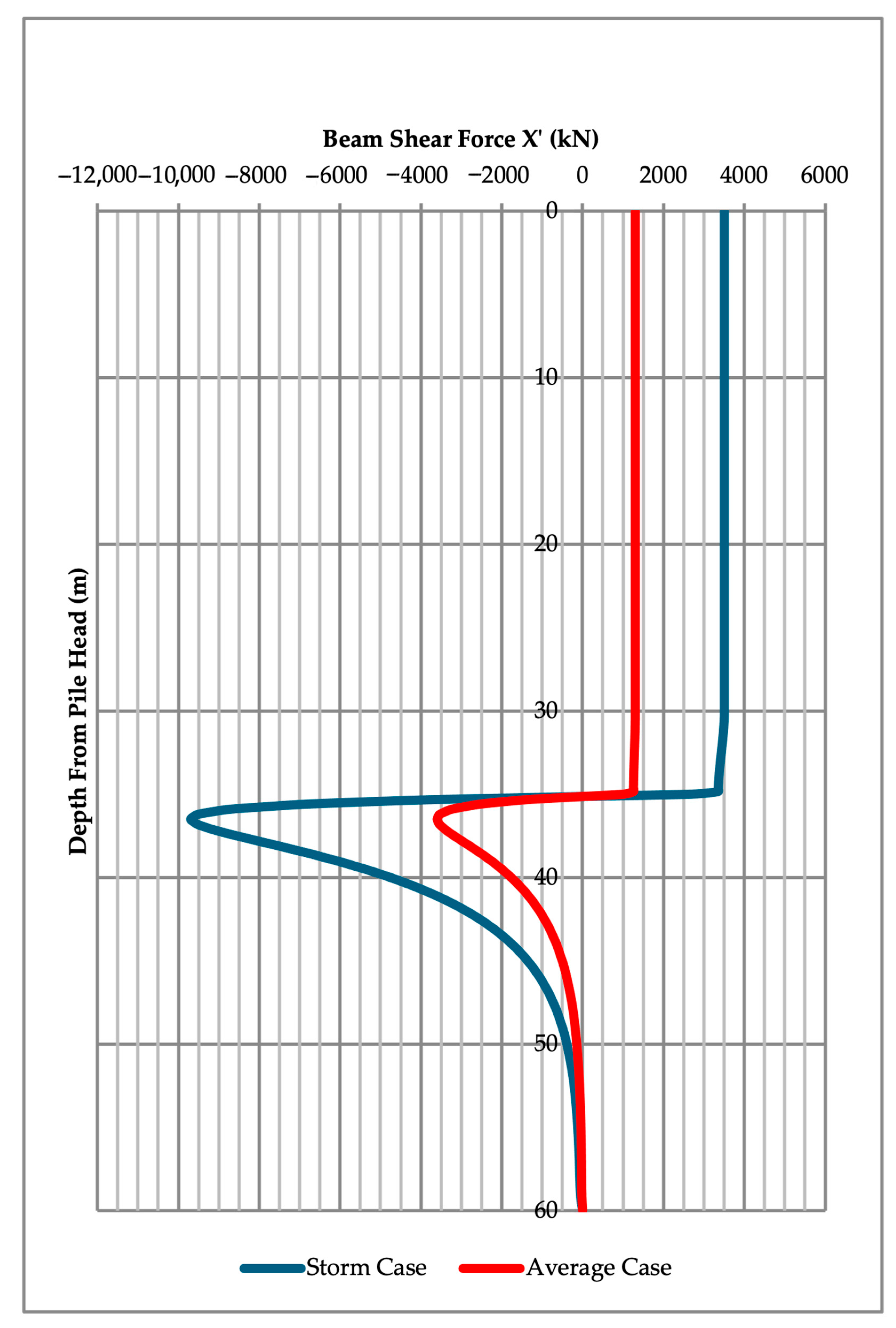
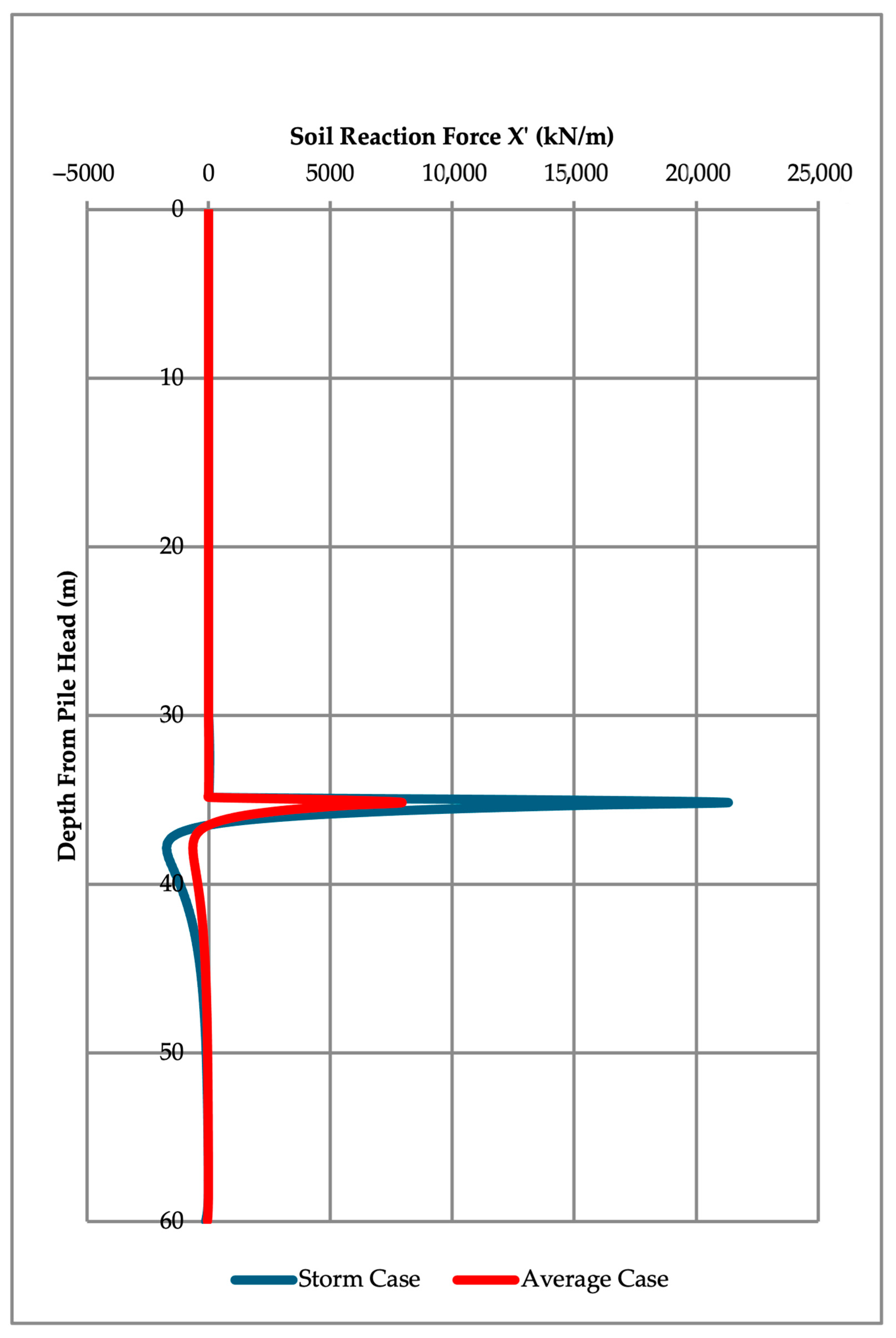
In the lateral pile displacement analysis, the maximum displacement observed in the average case is approximately 1.7 cm at the top of the monopile. The maximum displacement observed in the storm case is approximately 4.6 cm at the top of the monopile. In the beam moment analysis, the maximum beam moment observed in the average case is approximately 25,200 kN/m at the top of the monopile. The maximum beam moment observed in the storm case is approximately 67,800 kN/m at the top of the monopile. In the beam shear analysis, the maximum beam shear force observed in the average case is approximately 3600 kN, 36 m below the top of the monopile. The maximum beam shear force observed in the storm case is approximately 9700 kN, 36 m below the top of the monopile. In the rotation analysis, the maximum rotation observed in the average case is approximately 0.0006 rad, 20 m below the top of the monopile. The maximum rotation observed in the storm case is approximately 0.0016 rad, 20 m below the top of the monopile. In the soil reaction force analysis, the maximum soil reaction force observed in the average case is approximately 7900 kN/m, 35 m below the top of the monopile. The maximum soil reaction force observed in the storm case is approximately 21,300 kN/m, 35 m below the top of the monopile.
The results are generally consistent with expectations for displacement and bending moments. Deflection, bending, shear force, and rotation are all significantly greater in the extreme weather case. While the maximum lateral displacement for the average case is only around 1.7 cm, the lateral displacement in the extreme storm event almost reaches 4.6 cm. The 4.6 cm deflection is an approximately 0.0008% vertical deviation, which is relatively insignificant and will likely not be consequential in the competent geologic material supporting the foundation.
RSPile quantifies the impact of the water-induced shear forces along the foundation. These data are relevant to understanding the moment and how the foundation may experience rotation, but erosion and impacts on the visible structure as a result of shearing should also be considered. The chemical composition of the water will impact the degradation of the monopile material over time.
RSPile calculates the axial rotation of the monopile. In the extreme storm case, the maximum projected axial rotation is slightly over 0.0016 radians and is experienced at a depth of around 20 m, about 10 m above the seabed. At the seabed, a rotation of approximately 0.0012 radians is observed. The DNV industry standard indicates that the maximum allowable accumulated rotation at the seabed under the serviceability limit state (SLS) is 0.25° over the lifetime of the structure [
29], which is equal to approximately 0.004 radians. This characteristic force analysis satisfies the serviceability limit state.
Soil stiffness is independent of the shear force from waves acting on the monopile. Since the seabed is made of decently competent material, stiffness is high for the entire embedded depth of the pile. The soil reaction force, however, is not consistent between the two cases. In both cases, the reaction force is greatest at the loose sand–bedrock interface, but the maximum force in the average case is just over 8000 kN/m, while the maximum force in the extreme weather event is over 20,000 kN/m.
No vertical (z-axis) displacement is observed, as the foundation is fixed.
While the profile values vary based on wave loading, depths corresponding to peaks and minimum values for each analysis are consistent. Maximum displacement will occur at the top of the pile, maximum rotation will occur towards the bottom of the exposed section of the monopile, and maximum beam shear force will be endured around the interface between the sand and bedrock.
6. Limitations and Recommendations
This research considers wave forces as point loads as a preliminary analysis. This research is a simplification that aims to serve as an initial assessment of the structural impacts of wave loading. This research does not aim to comprehensively assess the impacts of dynamic wave cycles on monopile foundations, such as varying periods or velocities. Future detailed research may use different analyses to assess wave loading along foundations.
This research considers a single characteristic service load for serviceability limit state analysis. Future analysis should be conducted to consider cumulative effects for comprehensive SLS testing.
This research comprised a preliminary numerical analysis. Future assessments may involve experimental research to validate the results of this numerical analysis. Experimental verification is an important component in the development and design of an offshore wind farm. Other software programs may also be considered to implement different parameters and variables in numerical analysis. RSPile does not conduct slip or discontinuity modeling. More comprehensive geologic analysis is recommended to thoroughly characterize seabed conditions.
This research assumed a small-scale offshore wind farm for initial implementation in the Great Lakes area. Further research should be conducted to understand the feasibility of large-scale wind turbines in the area of study.
There are many other factors not considered in the scope of this study that will impact the feasibility of an offshore wind farm in Lake Huron. The development of karst formations can lead to instability, and prominent joint sets form weak planes in the bedrock. While the material is generally decently competent, rock mass characteristics cannot be neglected in detailed design for construction. Future studies may seek to quantify karst development impacts on fixed foundations and consider the potential of floating foundations as an alternative. Physical testing of site-specific vuggy limestone to conduct a driveability assessment is recommended to ensure safe pile driving in the identified region.
Ice loading is a relevant consideration in Lake Huron. Between 1973 and 2002, the area of study averaged 30 days of ice cover greater than or equal to 50% [
5]. Ice ridges and ice sheet collisions pose threats to monopile structures and impact other Great Lakes operations like hydropower generation and marine travel [
5]. Further research should characterize ice conditions in the area of study, and consider ice loading impacts on the platform of the monopile foundation. Material impacts of ice accumulation on offshore turbine platforms could also be investigated to develop a more comprehensive understanding of offshore wind turbine foundations in Lake Huron.
There are standard considerations with offshore wind farms, like maintenance, migratory disruptions, and other obstructions to naval transportation. An environmental assessment should be conducted on the area to ensure that environmental impacts are minimal and any potential negatives do not outweigh the benefits of additional power to the growing population of Eastern Ontario.
The nature of offshore wind farms means that they are heavily governed by the climate and weather conditions. The growing threat of climate change must be considered in long-term wind farm design and should be assessed and quantified through the hydraulic projections or climate forecasts. Storm magnitudes and frequency will likely increase with climate change, and the modeled extreme storm event may change.
The Lake Huron area has previously endured extreme weather events. Waterspouts, which are swirls of air and water that visually resemble tornadoes, have been spotted over Lake Huron [
30] and logically pose a threat to offshore infrastructure. Understanding the implications of these threats and how they may be exacerbated by climate change will prove critical to the successful design of an offshore wind farm with a design life of 30+ years.
There may be other climate-related factors, like changes in the temperature or pH of the lake water, which could impact the chemical composition or behavior of the monopile. Further chemical investigation would be beneficial to optimize the material design of an offshore wind turbine foundation for Lake Huron.


