Article

Production Reliability Technology Based on Vacuum Infusion Process Convergence to Design Strengthen Boat Safety

1
Design Innovation Sharing Center, Kaywon University of Art & Design, Uiwang 16038, Republic of Korea
2
Emsolution Co., Ltd., Suwon 16571, Republic of Korea
3
Department of Electronic Engineering, Semyung University, Jecheon 27136, Republic of Korea
*
Author to whom correspondence should be addressed.
Processes 2025, 13(7), 2025; https://doi.org/10.3390/pr13072025
Submission received: 27 January 2025 / Revised: 6 March 2025 / Accepted: 23 June 2025 / Published: 26 June 2025
(This article belongs to the Section AI-Enabled Process Engineering)

Abstract

In this paper, we develop technology to improve the stability and quality of boat equipment manufacturing through vacuum injection process fusion to increase the safety of boats. Safe mold design and fabrication are carried out to determine the resin flow rate and water flow rate of a boat, and the performance of vacuum maintenance work is guaranteed through the tensile and compressive strength of the manufactured hull and deck. When manufacturing the boat air mechanism (Aerostat), the adhesion between equipment materials and the deformation of the joints are very important factors for safety. Due to the nature of equipment manufacturing, process fusion to minimize manual process minimizes deformation after manufacturing through accurate manufacturing ratio. Accordingly, it is possible to accurately control the mixing ratio of resin and hardener as optimal conditions for boat drying and securing safety, and to convert optimal information into a database by analyzing working conditions over time such as resin flow rate and flow rate, thereby improving durability and quality. Through this, it is expected that production efficiency and safety design will be improved by enabling efficient production process management with a small number of personnel.

1. Introduction

With the revitalization of the global marine tourism industry, the water leisure system is expanding the use of boats for charity, scuba diving, lifesaving, and fishing on mother ships. Consumer patterns are diversifying, especially as the market expands from inland leisure boats to marine sports and leisure equipment. In particular, the high-speed sliding posture of small boats is greatly affected by the weight, buoyancy, and speed of the hull, depending on various marine activities such as high-speed police boats, marine safety structures, and recreational boats [1,2]. To this end, it appears in the form of burps and sinks in the process of balancing forces with dynamic hydrodynamics, and the resistance changes significantly as the port posture changes [3,4]. Figure 1 shows the status of various active boats, such as the Coast Guard and divers, on board.
Since underwater boats are often produced by hand, it is necessary to utilize a standardized production system for safety [5]. Therefore, it is possible to manufacture safe boats by integrating the vacuum injection technology require for underwater attachments, and the uniform mixing ratio of resin and epoxy in the production process [6]. Figure 2 shows the production flow of the boat manufacturing process.
Due to the nature of the boat operation, various types of small-scale production are carried out, and all processes are carried out manually, which determines the product quality according to the operator’s work efficiency and skill level [7]. In particular, depending on the operator’s manufacturing experience, the paint applied manually by mixing resin and hardener affects the operator’s health. Therefore, it is difficult to systematically manage quality and actively cope with defects. In addition, in boat production, which produces various types of small quantities, the optimal work arrangement for each workshop is essential, which affects not only the production efficiency but also the boat performance. Therefore, it is necessary to develop a process automation system that integrates the production process with the vacuum infusion method to improve the productivity of the hull mold [8,9,10].
In this paper, we develop vacuum infusion injection automation technology and process fusion technology to improve the stability and quality of the boat. The flow rate potential flow algorithm can be used to determine the flowability that occurs in the hull. Through these calculations, the hull of the boat is estimated using the estimated form of additional buoyancy and hull weight. The vacuum infusion method is used to inject the mixture of standardized resin and hardener into the hull mold. If the mixture is adsorbed into the hull along the mold in a short time, an evenly distributed increase in strength can be expected and deformation problem can be minimized. The developed system accurately controls the mixing ratio condition of resin and hardener and maintains optimal drying conditions. In order to secure the strength of the boat, the quality, including durability, is improved by analyzing information by model and optimization information on working conditions such as resin flow rate and resin flow chart over time.

2. Vacuum Infusion Method and Hull Design

For a high-speed boat to be safe, the streamlined design of the waterfront contacts and the balanced injection of the mixture according to the internal mold of the hull must ensure a constant balance of the hull’s left and right weight. When driving at high speed, the left–right imbalance mechanism is linked to a direct accident in the event of a scratch or collision caused by an underwater obstacle [11].

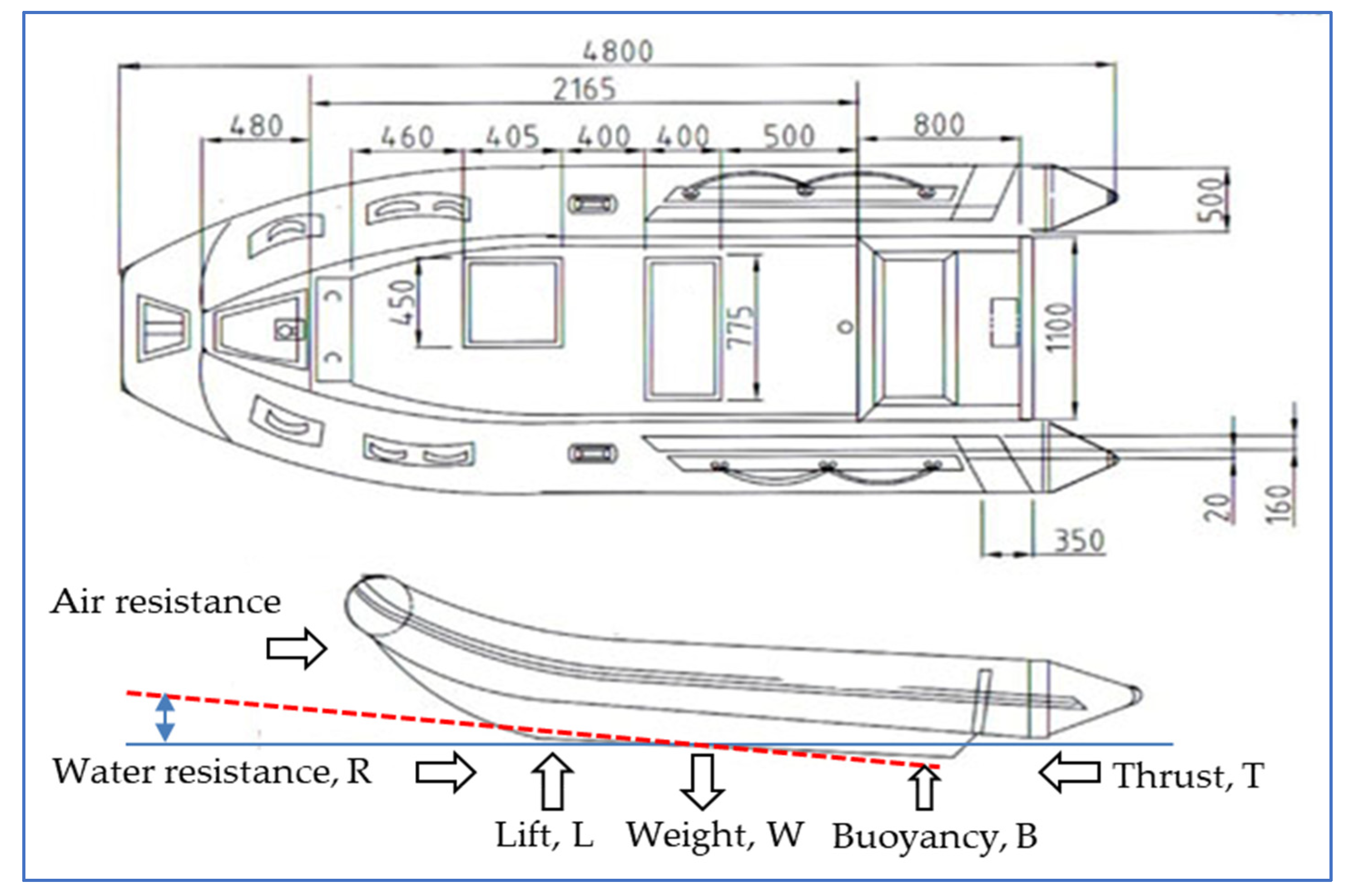
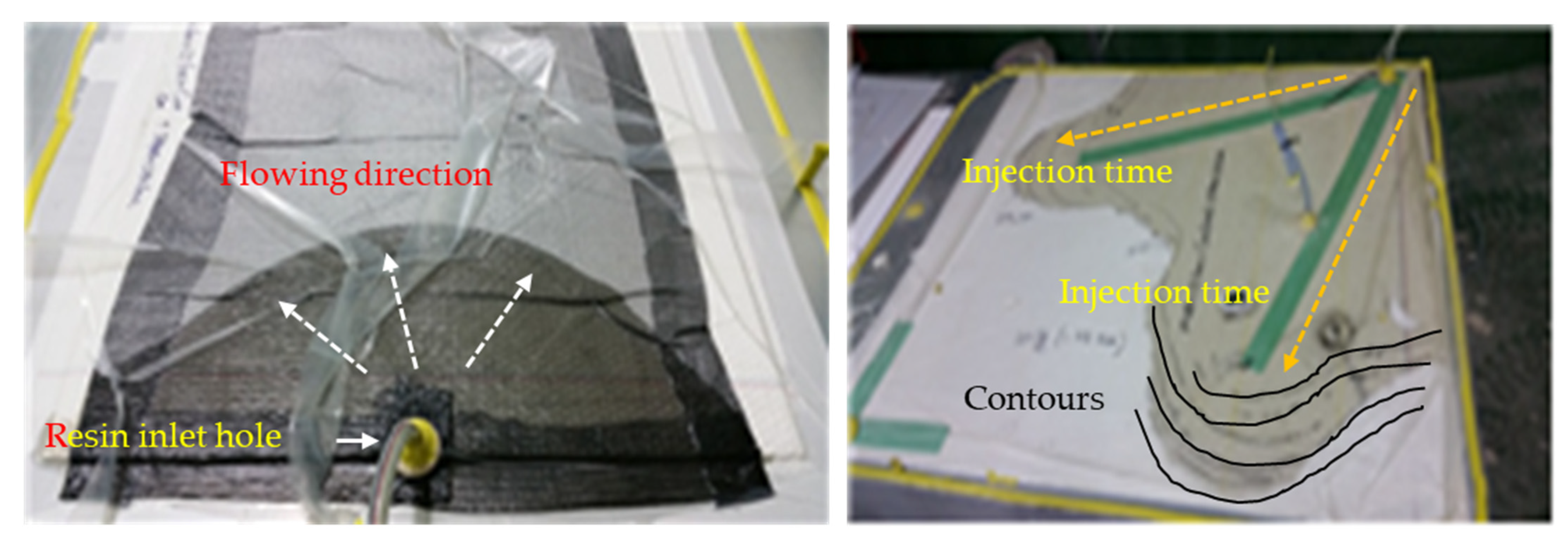
2.1. Analysis of 3D Liquidity of Boats

The key to the development of embedded mold design and molding technology is securing durability through grid reinforcement at the back of the mold. Automation coupling with coupling devices, maintenance of high gloss through vinyl ester gel coating, and the optimization of the boat design based on a 3D flow analysis all play an important role in the standardization and stable production of the system by reducing multi-tasking processes [12,13,14,15]. Figure 3 shows design examples of the total length, total width, tube thickness 500 m/m, compartment water 4 ea, loading load 1150 kg, eight people on board, propulsion engine 50–70 HP, and weight 185 kg.
During the suspension, the static buoyancy force (B) and the dynamic force, the flotation force (L), are in equilibrium with the hull weight, and in this process, the thrust force (T) by the thruster and the moment by the resistance (R) of the hull addition are added to determine the suspension posture. These forces and moments have an equilibrium relationship with the forward direction, the vertical direction, and the moment as shown in the following Equations (1)–(3).
R = T ( 1 t ) cos θ ,
W = B + L + T ( 1 t ) sin θ ,
W · L C G + B · L C B + L · L C L + T ( 1 t ) cos θ · L C T = 0 .
Here, t is the thrust reduction coefficient, and LCG′, LCB′, LCL′, and LCT′ are the distance between the force and the center of the moment, the θ has a trim angle. In the case of a high-speed runway, most of the weight of the hull is attributed to the flotation force. It is supported, and the hull weight, buoyancy, and flotation force are each centered in the port position. In the process of equilibrium with, it appears in the form of trim and flotation.

2.2. Air Boat Mold Design and Implementation

The key to the design and molding of the built-in extended mold of the boat is to secure durability through the reinforcement of the lattice at the back of the mold. The manufacture of boat equipment is based on automatic bonding using a coupling device and 3D flow analysis through vinyl ester gel coating, and design optimization plays an important role in standardizing and stabilizing the production of the system by reducing multiple work processes [16]. Figure 4 shows the equilibrium and weight-centered 3D flow analysis of the boat. The force moment balance equation for flow analysis is as follows.
In Figure 4, the blue outline shows the flow rate effect and underwater contact according to the fluid line to the side of the boat, and the numbers 5, 6, 7, 9 show the change according to the fluid line on the front. Equation (4) represents the change in the center of gravity position according to the change in the wired line on the side and front, and Equation (5) represents the change in distance from the center.
M p = F b ( M r + M i + M t + M p ) ,
X p = 1 M p [ F b X b M r X r + M i X i + M t X t + M m X m ] .
In Equation (4), M p   is the overall center of gravity of the ship, M r ,   M i ,   M t ,   and M p show the center of gravity variables transformed by the positions r, i, t, and p from the lower hull to the upper body. In Equation (5), X p represents the distance from the center of gravity that changes from the lower body to the upper body. Based on Equations (4) and (5), the force and moment balance equation and center of gravity are designed for 3D flow analysis [6,13].

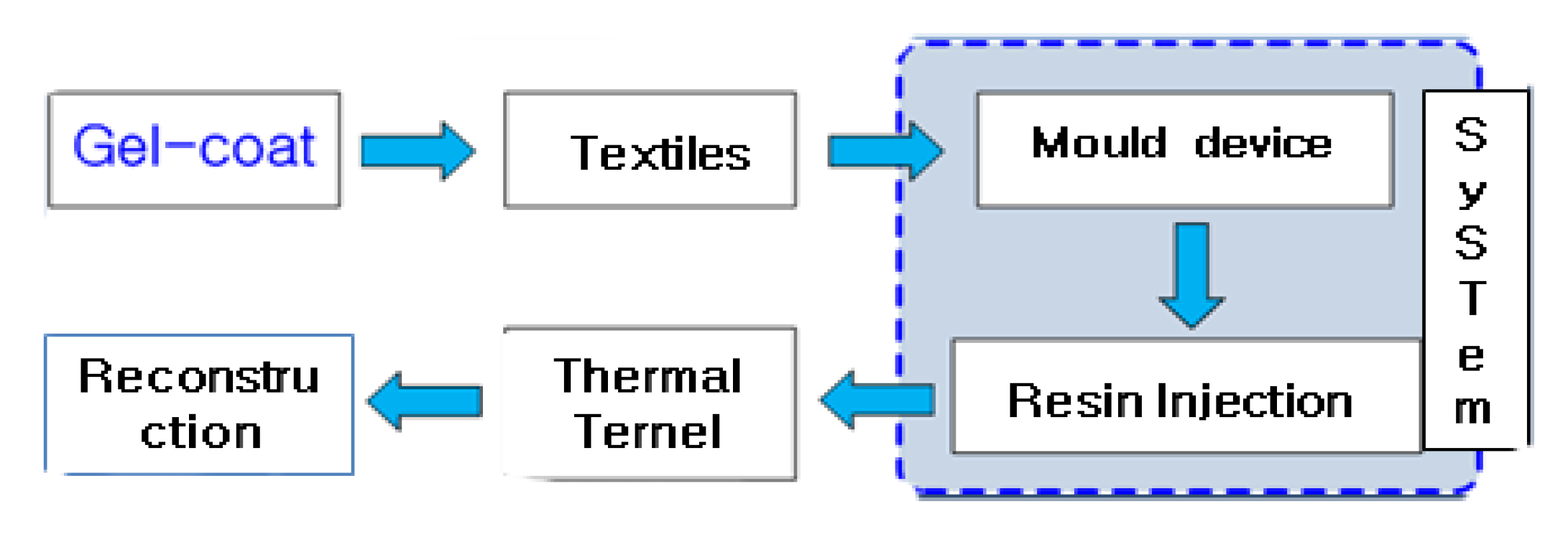
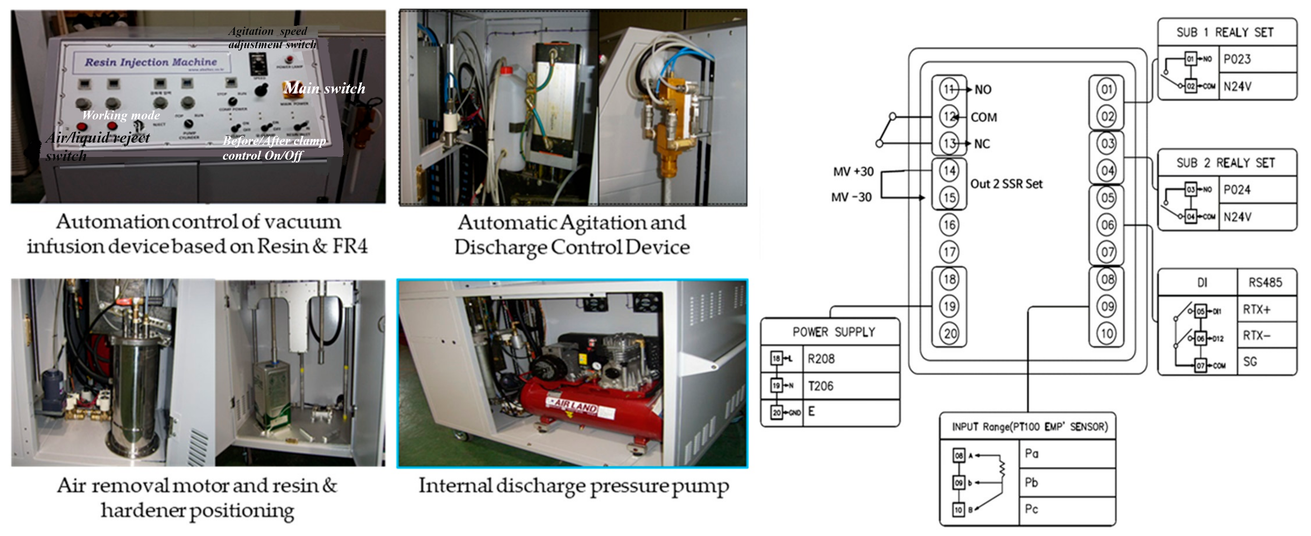
2.3. Vacuum Infusion Process Convergence Automation System

The development of automation technology for vacuum infusion process fusion automation has the function of automatically adjusting the mixing ratio of the resin and curing agent and automatically adjusting the discharge amount of the mixed resin and curing agent [16,17,18,19]. Figure 5 is a converged process of mold device and resin injection vacuum infusion process.
Figure 6 shows a system diagram that combines the vacuum infusion method and the production process by reflecting information on working conditions such as resin flow rate and flow chart, based on Figure 5. This vacuum facility resin injector aims to support the efficient production process even with a small number of people in the work process [20,21].
The development of the vacuum resin injector in Figure 6 and the system operation method that fuses the fiber lamination process enable a combination of RTM and injection that can perform the desired hourly discharge and mixture adjustment function [19,22]. Through this fusion process, a method for minimizing industrial accidents is demonstrated through experiments. At this time, Equation (6) Q, which is a method of mixing the curing agent, is a variable equation according to a mixing ratio of 0.5~4%, and Equation (7) ξ represents the impregnation rate.
Q = k A η P 1 P 2 L ,
ξ = f a b r i c   p e r m e a b i l i t y R e s i n   v i s c o s i t y × f l o w   d i s t a n c e .
Here, Q represents the resin flow ratio, fabric permeability, flow longitudinal section, viscosity, silver length, and pressure difference. Figure 7 shows the programmable logic control (PLC) of the backcom infusion system, and the control unit based on Figure 6. When power is input, it is controlled by each relay through the SSR output. At this time, RS485 manages data in parallel with a PC as necessary, and each relay part performs the function of mixing a resin material, and it is connected to a nozzle and used for molding.
By improving the process of mold design and manufacturing process, it is possible to standardize and optimize the design process through CAE/CAD design. And by identifying quality problems that appear during the manufacturing process, quality and productivity can be improved through the usefulness of the verified data [6,23]. In addition, the vacuum injection automation unit consists of an instrument panel, a stirrer and discharge control unit, an air removal motor, a resin hardener position correction, and an internal discharge pressure pump.

3. Manufacturing Convergence of Air Instrument and Boat Floor Molding

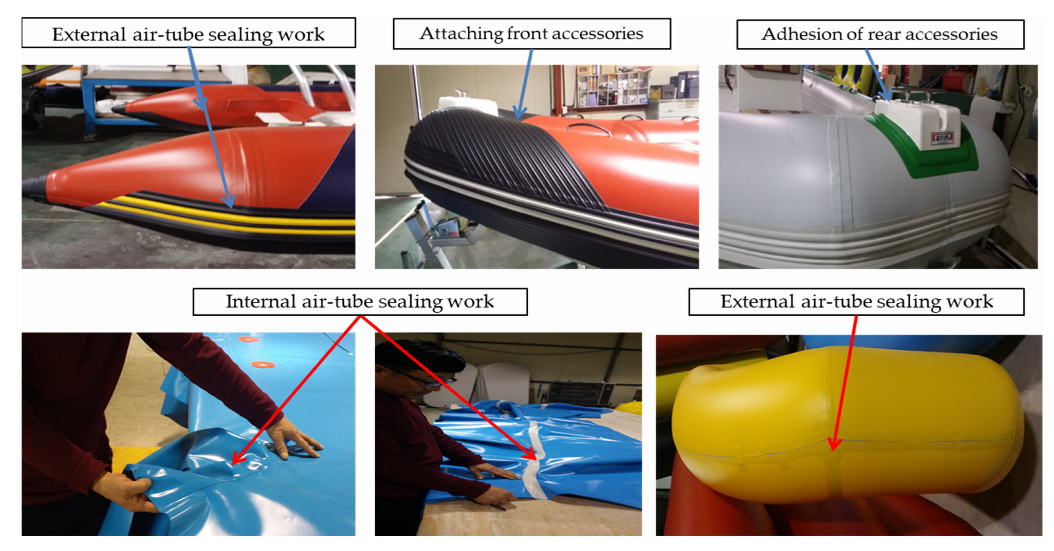
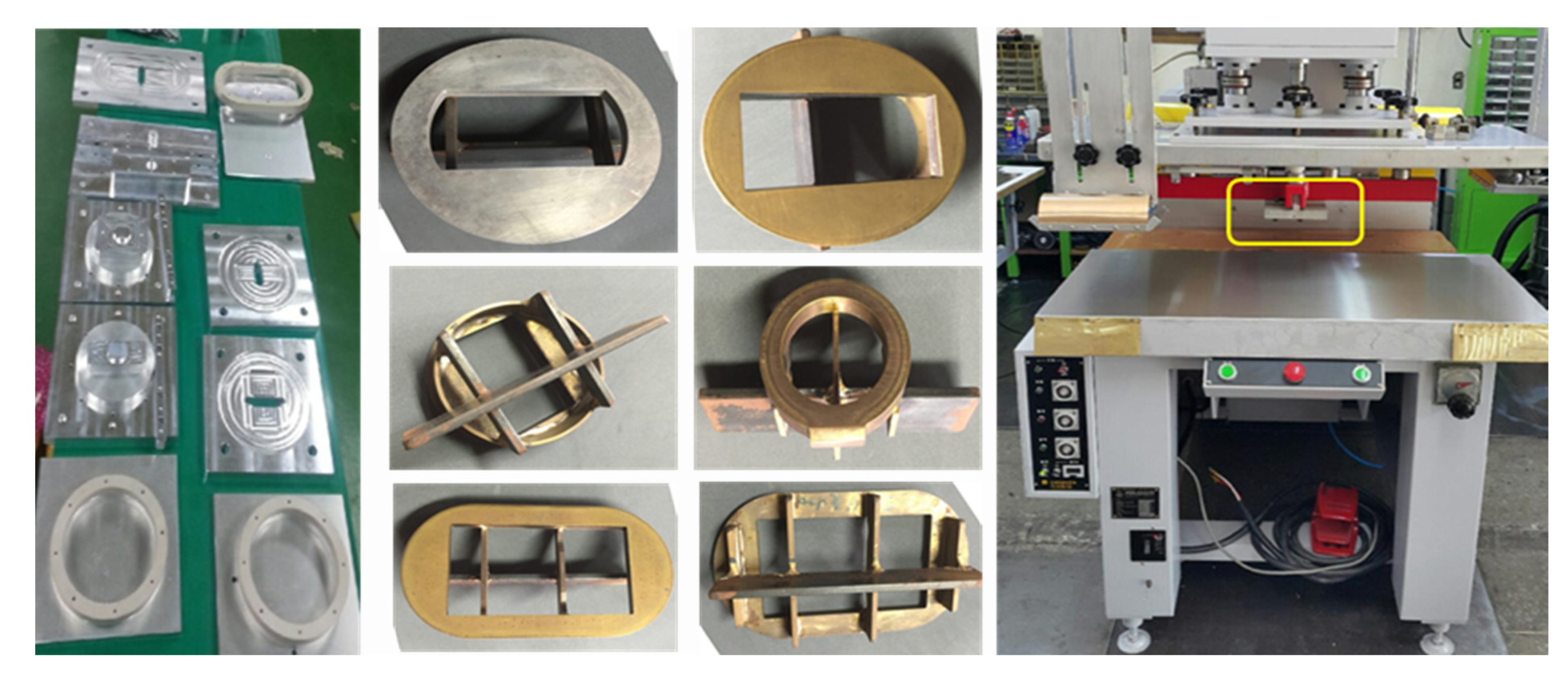
3.1. Air Instrument Implementation Technology

Since most of the processes are carried out manually when manufacturing the small boats in Figure 1, work efficiency and product quality are determined by the operator’s skill and experience. Therefore, if a defect occurs after the boat is completed, it is very difficult to actively cope with the defect correction [2,6,24]. Figure 8 shows manual processes such as air tubing and attaching accessories.
Table 1 shows the main facilities, daily working hours, and weight used for each unit operation.
In the main process in Table 1, improper posture and repetitive work cause fatigue and risks to the worker’s muscles. In particular, according to the worker’s production experience, there are risks depending on the worker’s skill level for each process, so systematic quality control is required. When various types of boats are produced on a small scale, production efficiency is linked to increased production costs. Therefore, a burden appears on the musculoskeletal system due to the manual work of accessories and wide joints according to the efficient work arrangement at each workplace. Table 2 shows the work checklist that burdens the musculoskeletal system.
According to the investigation of working conditions following the manual production of accessories and width joints, mold accessories that are repeated for more than 4 h a day during diaphragm manufacturing and repetitive work using the arms, elbows, and waist due to manual width joints, are closely related to the safety and production quality of workers. In addition, air tube leaks and defects can be fatal to productivity degradation. Table 3 shows improvements in the problems of this process. Currently, both width joints and beauty tapping processes of air tubes are performed manually, resulting in drops, breakages, or leaks. Accordingly, standardization and speed of work should be increased, and adhesions that do not fall off once attached should be maintained. Mechanization and automation are needed to identify the location of air tube accessories and attach them at once to minimize the human impact from the smell of adhesion and to accurately integrate accessories and molds. In particular, it is necessary to develop a fusion process that can increase productivity and reduce costs, since the amount of adhesion increases as production increases [25,26]. Therefore, if an air tube leak or defect occurs in Figure 8, the reliability of the boat decreases, which can have fatal consequences for safety. Table 3 suggests a way to increase the reliability and safety of the boat from these process problems.

3.2. Manufacturing Convergence of Boat Floor Molding

The molding is constructed with consideration of the variable that changes the center of gravity in the process of converting the entire center of gravity of the ship and the lower hull to the upper body [9,10,11]. At this time, the force and moment balance and center of gravity for 3D flow analysis are designed according to the center of gravity and the distance that changes from the lower body to the upper body, as shown in Equation (2). Figure 9 shows the manufacturing process of the boat floor molding based on the flow analysis.
It is important to develop specimens in order to manufacture small parts of boats. In particular, various types of specimens are data-based depending on the boat part. Figure 10 shows various specimen cases and a hot-sealing system. Hot-sealing with excellent adhesive performance is manufactured and used in the width joint or taping process of air-tube to prevent damage or leakage [6,27]. In particular, it is necessary to maintain a high degree of adhesion, check the exact location of air-tube accessories, and minimize human body impact due to harmful odors generated during bonding. In addition, as bonding work increases, peeling prevention plays an important role in the production efficiency, reliability, and safety of boats.

4. Experimental Results

Figure 11 is a sample of five samples, (a) hand-crafted specimen, and (b) specimens by vacuum infusion device. Pieces made by manual and bequem infusion methods can have a ratio of tensile and compressive strength. Despite the specimens being the same size, the weight of the specimen made of bequem infusion is about 48% lighter on average than that of the specimen made by hand, and the amount of resin used is smaller.
By comparing manual and vacuum injection tensile strength tests according to the certification of the Korea Institute of Construction and Living Environment (KICLE), a national accredited certification body, product quality can be improved through the automation of process automation technology.
The introduction of the database automatically adjusts the precise mixing ratio of resin and curing agent, the discharge amount of resin and curing agent mixture using sensors and drivers and guarantees the performance of vacuum maintenance work through tensile strength and compressive strength of hull and deck manufactured according to the mixing ratio of resin and curing agent [9,28]. Figure 12 shows the process of specimen production and weight-centered analysis during vacuum infusion work for database construction and performance analysis of specimens.
Figure 13 tests the strength of the hull manufactured using the vacuum injection method. It shows the performance evaluation test of the process unit through the vacuum film test.
Table 4 shows comparison values for the thickness and weight of specimens manufactured by manual and vacuum infusion methods shown in Figure 10 and Figure 11.
The slight difference between thickness and weight in Table 4 means that the resin content is constant. Therefore, comparing hull, deck weight, and resin consumption through the infusion method can be reduced by more than 40% compared to manual labor. In addition to the weight reduction in the hull relative to manual labor on the entire boat, vacuum infusion methods can expect a reduction in more than 50% resin. As a result, the total weight reduction in the boat can also be expected to improve fuel efficiency.
Table 5 compares the tensile and compressive strength of vacuum infusion and hand-made composite materials. A database of physical properties was established based on the test and certification of the nationally accredited agency (Korea Institute for Construction and Environmental Testing). Here, the tensile strength of the specimen produced by the Becum infusion method is only 30% thick, but the tensile strength is superior to that of the specimen made manually.
In Table 5, it can be seen that in the case of specimens having the same thickness, the compressive strength is also much improved when using the vacuum infusion method. In addition, analysis conditions for analyzing the thickness, weight, and resin flow rate according to the mat lamination and resin type were presented in the DB. When the number of stacks was the same, both the thickness and weight of the vacuum infusion were smaller than those of the manual case, which means that the proportion of the resin absorbed by the products made by the vacuum infusion is small.
Table 6 shows the database example for analyzing thickness, weight, and resin flow rate (min/cm) according to the mat lamination and resin type. As confirmed, when the number of stacks was the same, both the thickness and weight of the vacuum infusion were smaller than those of the manual operation, which means that the proportion of the resin absorbed by the products in the vacuum infusion is small.
Table 7 compares the results of changes in thickness, weight, and flow rate of products manufactured according to conditions, and it can be confirmed that the vacuum infusion method has advantages such as thickness and weight reduction effect, reduction in working time, and uniformity of molding production. Here, ⤓ and ⤒ account for the amount of decrease and increase, respectively
Safety concerns are an important factor because boat production, through the small-scale production of various varieties, is mostly performed by hand. Vacuum injection molded boats show an average of about 1.5 times superiority in terms of strength, repulsion, and bending compared to other stacking methods [26,27,28]. Therefore, the results of the research so far are as follows.
First, vacuum-molded boats are about 50% more powerful than laminated boats. Second, they block the possibility of weak areas by removing air that may occur in the gaps between each composite material during the lamination process. Vacuum-molded boats are about 30% lighter than regular boats, are safe to float on the water, and can move faster with the same force. Therefore, they are very useful because they can load more equipment and materials. Third, composite materials are more fire-resistant. The reason why FRP vessels are vulnerable to fire is because of the PVC included in the lamination, and vacuum molding can increase the proportion of glass fibers due to the nature of the method. Fourth, they have several advantages because of their high compressive strength between materials and excellent insulation properties.

5. Conclusions

In this study, process convergence was presented based on the vacuum infusion injection system and the performance was compared with manual work through boat design and manufacturing. In particular, the database was established through process convergence during the manufacturing process to differentiate the samples that can build the safety and reliability of the boat.
Through the three-dimensional flow analysis of force and moment, the boat was designed in consideration of the variables that change in the process of converting balance, center of gravity, and overall center of gravity from the lower body to the upper body. At this time, it shows the process of manufacturing a boat floor molded article based on the flow analysis according to the center of gravity and distance that changes from the lower body to the upper body. The tensile strength of the vacuum infusion injection method and the handmade composite material and the compressive strength were compared through the specimen manufacturing, and it was found that the tensile strength of the specimen manufactured by the vacuum infusion injection method was only about 30% thicker than that of the handmade specimen, but the tensile strength was more than 50%. In addition, with the effect of reducing thickness and weight, the working time is shortened, and the possibility of uniformly manufacturing the molded article can be confirmed.
This study can ensure the safety and reliability of boats due to the revitalization of the leisure industry, and it can prevent safety accidents that can occur as the center of unevenly designed ships changes during the process of high speed. In addition, an injection method was proposed to minimize the damage that could occur due to underwater rocks or collisions.

Author Contributions

Methodology, Supervision and conceptualization, project administration, visualization and design, J.-H.Y.; formal analysis, investigation and synthesis, H.-M.P.; validation and resources, software and methodology, writing—original draft, writing—review and editing, D.-H.Y. All authors have read and agreed to the published version of the manuscript.

Funding

This research received no external funding.

Data Availability Statement

The original contributions presented in this study are included in the article. Further inquiries can be directed to the corresponding author.

Acknowledgments

This research is a research project conducted with the support of the Korea Maritime Fisheries Science and Technology Promotion Agency (Project No. RS-2025-16322969) with the financial resources of the Ministry of Oceans and Fisheries of the Republic of Korea.

Conflicts of Interest

Authors Jong-Hwa Yoon, Hoon-Min Park, Dal-Hwan Yoon declare that the research was conducted in the absence of any commercial or financial relationships that could be construed as a potential conflict of interest. The company had no role in the design of the study; in the collection, analyses, or interpretation of data; in the writing of the manuscript, or in the decision to publish the results.

References

  1. Puls, J.; Fassbender, F.R. Method and Device for Detecting the Risk of a Person Drowning in Water. Patent Application No. WO2008055593A1, 15 May 2008. [Google Scholar]
  2. Oh, D.K.; Lee, K.W.; Lee, C.W. Basic Design of 40ft Class Pleasure Boat based on Digital Mock-up. J. Korean Soc. Mar. Environ. 2011, 17, 283–289. [Google Scholar] [CrossRef]
  3. Korean Society for Research and Research. A Study on the Status of Leisure Sports Industry. J. Korean Soc. Res. Res. 2023, 24, 33–79. [Google Scholar] [CrossRef]
  4. Available online: https://www.sports.re.kr/front/board/bs/boardList.do?board_seq=72&menu_seq=862 (accessed on 25 January 2025).
  5. Lee, S.W.; Kim, S.G.; Lee, J.H.; Hong, J.W.; Lee, Y.J.; Schwarzbach, H. A Study on Marine Tourism Policies to Upgrade the Marine and Pleasure Boat Industry of Korea; Korea Maritime Fisheries Development Institute: Busan, Republic of Korea, 2008. [Google Scholar]
  6. Shen, R.; Liu, T.; Liu, H.; Zou, X.; Gong, Y.; Guo, H. An Enhanced Vacuum-Assisted Resin Transfer Molding Process and Its Pressure Effect on Resin Infusion Behavior and Composite Material Performance. Polymers 2024, 16, 1386. [Google Scholar] [CrossRef]
  7. Yoon, D.H.; Kim, S.H.; Min, H.G. Development of Boat Aerostat for the Safety Strengthen based on the Manufacture Convergence. Korean J. Saf. Cult. 2020, 9, 25–32. [Google Scholar]
  8. Lee, D.K.; Jeong, Y.K.; Shin, J.G. Development of a Factory Layout Design System using Leisure-Boat Building Process. J. Soc. Nav. Archit. Korea 2013, 50, 14–24. [Google Scholar] [CrossRef]
  9. Choi, S.S. A Study on Hull Form Development of Polyethylene Boat. J. Korea Acad.-Ind. Coop. Soc. 2013, 14, 4726–4732. [Google Scholar]
  10. Khalaquzzaman, M.; Lee, S.J.; Hossen, M.M. Reliability Assessment of NPP Safety Class Equipment Considering the Manufacturing Quality Assurance Process. J. Nucl. Eng. 2023, 4, 421–435. [Google Scholar] [CrossRef]
  11. Jeong, U.C.; Kwon, S.Y.; Choi, J.H.; Kim, D.J.; Hong, K.S. Study of Hull Form Development and Resistance Performance of Catamaran-type High Speed Fishing Leisure Boat. J. Ocean Eng. Technol. 2013, 27, 1–6. [Google Scholar] [CrossRef]
  12. Kang, N.S.; Yoon, H.K. A Study for the Conceptual Design of a Small Leisure Boat Handling Simulator. J. Korea Soc. Simul. 2013, 22, 99–107. [Google Scholar] [CrossRef]
  13. Jaskowska, K.; Daily, J.; Budi, M.; Jordan, A.; Habicht, S. Port Security and Emergency Response Using Autonomous Systems: Virginia Pilot Program; CNA: Arlington, VA, USA, 2024. [Google Scholar]
  14. Yoon, J.H.; Yoon, D.H. Implementation of a GAS Injection Type Prefabricated Lifting Device for Underwater Rescue Based on Location Tracking. Adv. Sci. Technol. Eng. Syst. J. 2023, 8, 78–86. [Google Scholar] [CrossRef]
  15. Oh, G.H.; Yoo, J.H. Numerical Prediction of Running Attitude and Resistance of Planing Craft. J. Soc. Nav. Archit. Korea 2013, 50, 95–103. [Google Scholar] [CrossRef]
  16. Lin, J. Resin Molding Apparatus, Resin Molding Method and Resin Container. Patent No. KR101059936B1, 26 August 2011. [Google Scholar]
  17. Gokai, U. Laminate Modeling Device and Method. Patent Application No. PCT/JP2010/058649, 2 December 2010. [Google Scholar]
  18. Available online: https://www.sciencedirect.com/topics/materials-science/vacuum-infusion (accessed on 25 January 2025).
  19. Yoon, D.H.; Zhao, X.; Lee, C.H. Vacuum Infusion System for Manufacture Process Convergence and Automation of Boat. J. IKEEE 2018, 22, 274–280. [Google Scholar]
  20. An, S.; Kim, J.-S.; Roh, H.D.; Kim, W.-D.; Lee, J.; Um, M.-K. Effect of Peel Ply on Resin Flow during Vacuum Infusion. Materials 2023, 16, 4421. [Google Scholar] [CrossRef]
  21. Osipov, E.V.; Bugembe, D.; Ponikarov, S.I.; Ponikarov, A.S. Comprehensive Modeling of Vacuum Systems Using Process Simulation Software. ChemEngineering 2024, 8, 31. [Google Scholar] [CrossRef]
  22. Available online: https://alliedfibreglass.co.za/advantages-and-disadvantages-of-vacuum-infusion (accessed on 25 January 2025).
  23. Grisin, B.; Carosella, S.; Middendorf, P. Vacuum Chamber Infusion for Fiber-Reinforced Composites. Polymers 2024, 16, 2763. [Google Scholar] [CrossRef]
  24. Atake, H. Process and Apparatus for Effecting Injection-Molded in Foil Decoration. Patent No. KR100350582B1, 28 August 2002. [Google Scholar]
  25. Schagatay, E.; Aman, P.A. Repeated freediving—An efficient and safe method to rescue subjects trapped in cars underwater. Saf. Sci. 2019, 118, 752–756. [Google Scholar] [CrossRef]
  26. Yoon, D.-H.; Lee, J.-H. Boat Aerostat Production Apparatus and Method for Safety Strengthen Based on Manufacture Convergence. Patent No. 1020200137878, 22 October 2020. [Google Scholar]
  27. Bonfitto, A.; Amati, N. Mechanical Construction and Propulsion Analysis of a Rescue Underwater Robot in the case of Drowning Persons. Appl. Sci. 2018, 8, 693. [Google Scholar] [CrossRef]
  28. Korean Society for Research and Research Science and Technology. System Assessment and Validation for Emergency Responders (SAVER); U.S. Department of Homeland Security: Washington, DC, USA, 2021.
Figure 1. Boarding status of various active boats.
Processes 13 02025 g001
Figure 2. Production flow of boat.
Processes 13 02025 g002
Figure 3. Force diagram in running boat condition.
Processes 13 02025 g003
Figure 4. Equilibrium and weight-centered 3D flow analysis of the boat.
Processes 13 02025 g004
Figure 5. Process convergence flow diagram of vacuum infusion.
Processes 13 02025 g005
Figure 6. Layout of the vacuum infusion wiring diagram.
Processes 13 02025 g006
Figure 7. PLC algorithm of the automated interlocking circuit control unit.
Processes 13 02025 g007
Figure 8. Examples of manual processes such as air tubing and accessories.
Processes 13 02025 g008
Figure 9. Manufacturing process of floor molding.
Processes 13 02025 g009
Figure 10. Various specimen cases and a hot-sealing system.
Processes 13 02025 g010
Figure 11. Sample of five samples. (a) Hand-crafted specimen; (b) Specimens by infusion method.
Processes 13 02025 g011
Figure 12. Weight-centered analysis during vacuum infusion work.
Processes 13 02025 g012
Figure 13. Performance evaluation for hull manufactured and vacuum film test.
Processes 13 02025 g013
Table 1. Unit action details.
Process NameUnit WorkMajor FacilitiesTime/DayUnit Weight
1Tailoring workDrawing a fabric patternHand cutting machineMore than 4 h20 Kg
Bottom drawing foundation-
2Making and working with accessoriesMaking Accessory MembraneManual operationMore than 4 h3 Kg
Fabric adhesion3 Kg
3Width jointFabric piecxe adhesionManual operationMore than 4 h3 Kg
4Addition widthFabric cylindrical bondingDrier, sharp knife, ScissorsMore than 4 h5 Kg
Press to trim the adhesive area-
5Make-up tapeMake-up tape gluingManual operationMore than 4 h5 Kg
Trim the adhesive area-
6Bottom adhesionBoat post adhesionCutter, KnifeMore than 4 h5 Kg
Boat bottom adhesion-
7Accesory adhesionRubbing and Bottom adhesionManual operationMore than 4 h5 Kg
Adhesion of accessories-
8PackagingBoat-folding boxBending, Packaging, BoxingMore than 4 h25 Kg
Place movement after bending25 Kg
Table 2. Task check that is a burden on the musculoskeletal system.
SortationExposure Time/DayBody PartsWorking Posture ContentWeight/Exposue Frequency
Work 1More than 4 hHand, wrist, arm, shoulderData inputFrequency
Work 2More than 2 hWrist, elbow, shoulderRepeat the same action
Work 3More than 2 hArm, shoulderTask in which the elbow is heard by the body
Work 4More than 2 hNeck, waistBending or twisting without changing posture
Work 5More than 2 hKnee, waistSquatting knees
Work 6More than 2 hFingerFinger-grabbing workCarrying more than 1 kg
Catch more than 2 kg
Work 7More than 2 hHandAct of lifting or catching an objectLift and hold objects greater than 4.5 kg
Work 8More than 2 hWaistWork of carrying things25 Kg/day at least 10 times
Table 3. Proposed method for reliability and safety of the boat.
No.Analysis ContentsImprovments
1Prediction of boat position through 2D flow analysisPrediction of boat posture by performing optimized flow analysis through 3D design
2Rely on the operator’s skill by hand during the production of Air-TubeStandardized automation process from experiential fabrication in tube fabrication
3Boat performance based on the angle of the mold and operator’s experience in designing the moldSecure the safety and reliability of the boat through the development of the proposed construction method
4Production yield problems and boat performance depend on manual work and affect safety and reliability when making moldsContribute to improved production yield, improved boat performance and stability through the development of convergence processes and automation of production lines
5Insufficient production quality controlPC-based database and monitoring with daily, weekly, and monthly resource management
Table 4. Comparison values for the thickness and weight of specimens.
SortationSample 1Sample 2Sample 3Sample 4Sample 5Average
Manual Process
01
Thickness (mm)119.29.5101110.1
Weight (g)11.5129.6111010.7
Manual Process
02
Thickness (mm)10.8129.21010.510.5
Weight (g)10.912.19.610.210.610.6
Vacuum infusion
01
Thickness (mm)66.2666.36.1
Weight (g)5.8665.86.15.9
Vacuum infusion
02
Thickness (mm)65.65.865.95.6
Weight (g)5.95.65.765.95.8
Table 5. Comparisons of the thick, tensile, and compressive strength.
SortationSample 1Sample 2Sample 3Sample 4Sample 5Average
ManualThickness (mm)6.76.86.66.76.76.7
Strengthen powerAve. 18.46 k g / m m 2   (181 MPa)
Depression powerAve. 20.40   k g / m m 2 (200 MPa)
Vacuum infusionThickness (mm)2.42.22.32.32.32.3
Strengthen powerAve. 27.44   k g / m m 2 (269 MPa)
Depression powerTemp. value (Thickness 6.7 mm)—Ave. 32.68   k g / m m 2
Real value (Thickness 2.3 mm)—Ave. 11.22   k g / m m 2
Table 6. Database example for analyzing thickness, weight, and resin flow rate (min/cm).
NoStacking MethodResinTempered Glass FiberNumber of Stacks and OrderThickness (mm)Weight (cm/g)Flow Rate ( m 3 / h ) Operation Mash
01ManualG-713BTM450, ROVING570M. M. Rx2
(six sheets)
4.95.7--
02FH-123NHL4.95.9--
03UV-R14.95.6--
04Infusion-01G-713BT2.632.50.43Part
Distribution
05FH-123NHL2.612.30.42
06UV-R12.62.10.46
07Infusion-02G-713BTM450, L T600, DB400, COER, DBL600M, LT, DB, CO, DBL
(five sheets)
6.15.940.27
08FH-123NHL6.05.960.3
09UV-R15.85.650.31
10G-713BT6.160.7Entire
Distribution
11FH-123NHL6.155.90.75
12UV-R165.80.78
Table 7. Comparison of the results of changes in thickness, weight, and flow rate of products.
NoTermsManualVacuumNote
1Resin weight160 kg80 kg50% (⤓)
2Glass fiber80 kg60 kg25% (⤓)
3Ship weight240 kg140 kg42% (⤓)
4Manufacture10820% (⤓)
5Intensity181 MPa269 MPa49% (⤒)
6Pressure strength200 MPa320 MPa60% (⤒)
7Ship edge effectivenessMinimize the friction area between ship and water for the sharpened ship edge part
8Ship out partno bending the line and surface
9Speed upAbout 15%
10Fuel efficiency10%
11SafetySafety sense for 7 estimated terms
Disclaimer/Publisher’s Note: The statements, opinions and data contained in all publications are solely those of the individual author(s) and contributor(s) and not of MDPI and/or the editor(s). MDPI and/or the editor(s) disclaim responsibility for any injury to people or property resulting from any ideas, methods, instructions or products referred to in the content.

