1. Introduction
For decades, boron neutron capture therapy (BNCT) has been considered an innovative type of radiotherapy that uses neutron irradiation to destroy cancer cells [
1]. However, traditional BNCT may not be adopted in hospitals since it should be installed at sites near the research reactor. Accelerator-based BNCT (AB-BNCT) systems have thus attracted much attention from researchers around the world [
2], as it is feasible to install these systems in hospitals for the treatment of more patients. The main parts of an AB-BNCT system includes intense ion sources, accelerator tubes, transport systems for intense beams, beam diagnostics and control systems, the neutron source (i.e., neutron production reactions), the appropriate coolant channel or thermal management system, etc. Beryllium (Be) is usually adopted as the target material in an AB-BNCT system for producing a secondary neutron. Due to the thermal and mechanical loading from the impingement of high-intensity proton beams from the accelerator, the Be target should sustain its integrity during the long-term operation of an AB-BNCT system. Therefore, it is crucial to conduct investigations to determine the appropriate thermal management for the design of an AB-BNCT system. A thermal management design should reduce temperature increases in the Be target to prevent the material from melting and maintain uniform temperature distribution to prevent excess mechanical loading from thermal shock [
3].
Our review of the literature reveals that little research has been conducted on thermal management for AB-BNCT systems. The University of Tsukuba developed an AB-BNCT facility [
3] using Be as the neutron target material. This Be target system was designed using Monte Carlo estimation, and heat removal analysis was performed using ANSYS. Ammugan et al. [
4] investigated the thermal shock response of various Be targets, which was induced by high-energy and high-intensity proton beams at CERN’s HiRadMat facility. Carpenter [
5] discussed the motivation for using gallium to cool targets for compact accelerator-based neutron sources. Analytical calculations were performed to obtain the temperature of the target and the drops in pressure across the cooling channel. He also recommended that numerical thermal–hydraulic analysis be conducted when designing the coolant channel. Hu et al. [
6] performed a CFD heat transfer simulation in a rotating target system with a Gaussian beam and a uniform beam. According to the simulation results, the equilibrium temperatures of the Li target with the Gaussian beam are 102, 144, and 142 °C. These values are lower than the melting point of Li. They also reported that the maximum temperature of the target and cyclic thermal stress could be reduced by increasing the rotating speed.
A single-phase convection mechanism is traditionally designed for heat removal for AB-BNCT systems. Refrigeration equipment and a high-capacity pump are needed to obtain cooling water at a lower inlet temperature and a higher flowrate, which can provide adequate heat removal in these systems. However, these additional sets of equipment would also increase construction and operation costs for AB-BNCT systems. With the advantage of greater heat removal, the boiling heat transfer mechanism may lower the peak temperature, as well as lead to more uniform distribution in the wall temperature, which reduces thermal degradation for the target for long-term operation. Therefore, we investigate the feasibility of applying boiling heat transfer to the thermal management for AB-BNCT systems in this work by way of CFD simulations. The simulation domain in the present work only consists of the coolant channel and Be target. The CFD boiling model has been assessed against the experimental data from previous works [
7,
8], which includes a two-fluid boiling model for the water and vapor phases with interfacial exchange models and a wall heat flux portioning model (RPI model) [
9]. With the validated results, this CFD boiling model can be used with confidence to assist in designing thermal management for AB-BNCT systems.
3. Results and Discussion
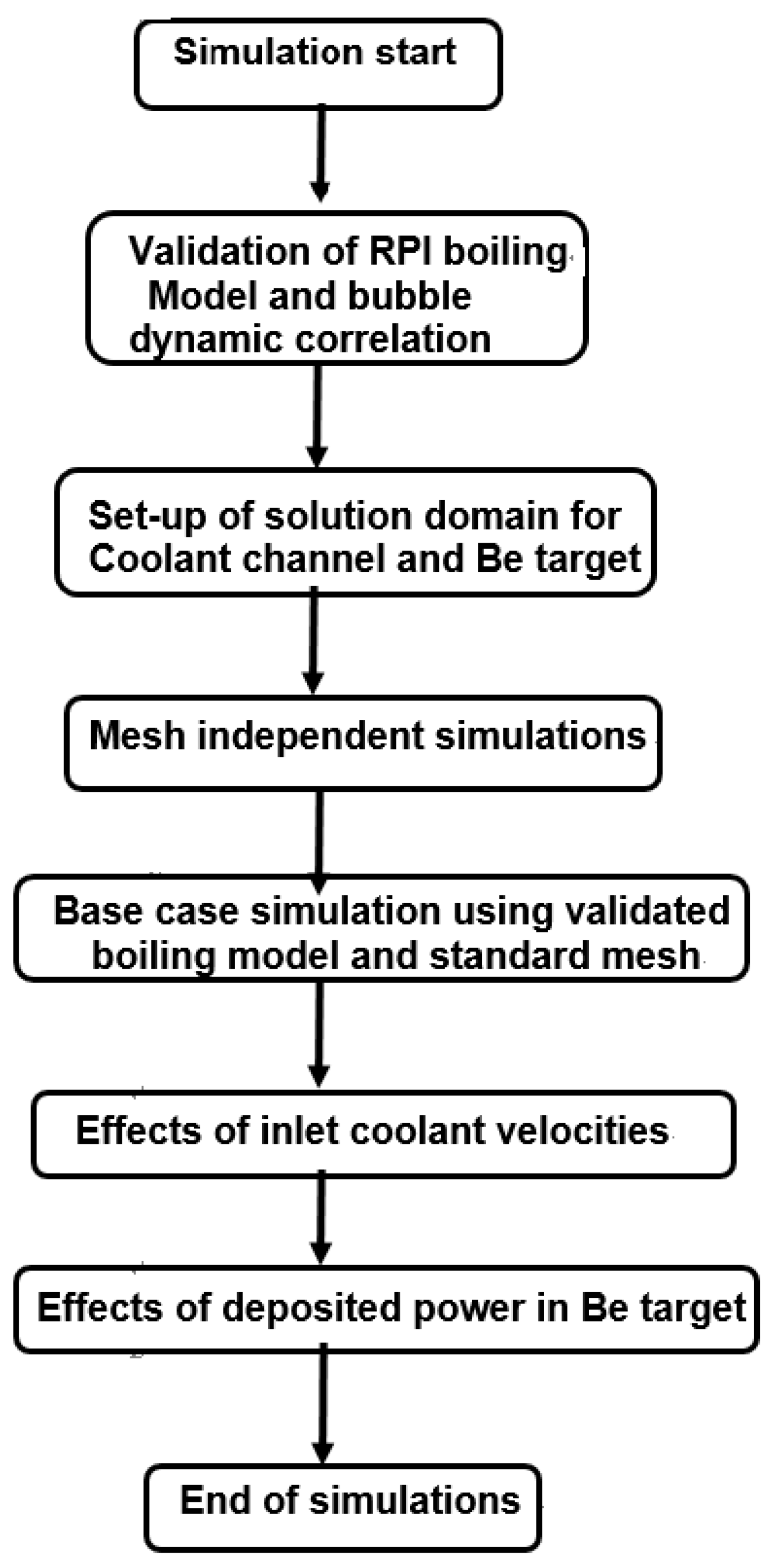
As described above, this study investigates the feasibility of thermal management through the boiling heat transfer mechanism for the Be target of an AB-BNCT system by way of CFD simulations. This CFD model includes the conservation equations of mass, momentum, and energy for both the water and vapor phases, the SKE turbulence model, the RPI wall boiling model, interfacial transfer models, and bubble dynamics models. A flow chart of the present simulation work is shown in
Figure 1.
Two benchmark cases [
7,
8] are used to validate the CFD boiling model proposed in the present work.
Figure 2 shows the simulation layouts for these two validated cases. The corresponding simulation conditions are indicated in
Table 2. The mass flux (
Gin) and the temperature (
Tin) are set as the inlet boundary conditions. The pressure (
Pout) is set at the outlet of the pipe. The axisymmetric boundary condition is applied along the pipe axis so that the 2D plane can be used to simulate the 3D pipe. Constant heat flux is applied on the heating wall. Structured rectangular mesh models with dimensions of 14 × 200 and 14 × 150, respectively, are set for these two cases.
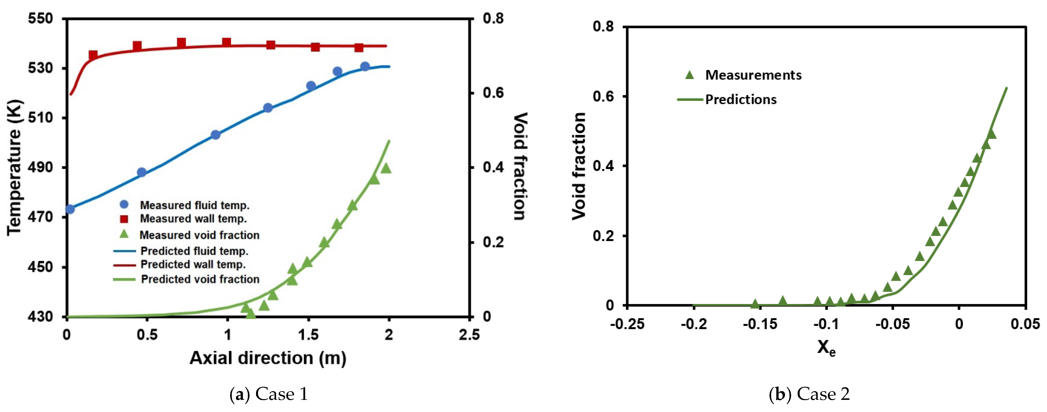
Figure 3a displays a comparison of wall temperature, average fluid temperature, and average void fraction along the axial direction of the heat wall between the measurements (dots) [
7] and predictions (lines). The good agreement shown in this comparison reveals that the CFD boiling model proposed in this paper can reproduce the wall/fluid temperature distributions from the experimental data [
7]. A comparison of these results with those of Zhang et al. [
8] are presented in
Figure 3b, which shows the average void fraction (
α) versus the thermal equilibrium quality (
Xe). Observation of this figure shows that the relationship of
α vs.
Xe predicted from the present boiling model corresponds well with the measured data. These agreement results confirm that the present CFD boiling model can be confidently applied to simulations of boiling heat removal for the Be target of an AB-BNCT system.
For the AB-BNCT system designed by Heron Neutron Medical Corp, the high-energy and high-intensity protons emitted from the accelerator would impinge on the Be target. The
9Be (p, n) reaction is exothermic and can thus deposit more heat in the target. A thermal management system should be designed to efficiently remove this high energy generation so as to withstand the thermal and mechanical loadings for the Be target during long-term operation. In the present work, the simulation domain for the thermal management of the AB-BNCT system only includes the coolant channel and Be target.
Figure 4a shows the solution domain for the AB-BNCT system simulated in the present work. The corresponding mesh models are also illustrated in plot (b). As shown in
Figure 4a, a simple coolant channel with a rectangular cross-section of 8 cm (W) × 1 cm (H) and a length of 18 cm (L) is attached to the round Be target with a diameter of 7 cm and a thickness of 5.5 mm. The target heat source, created by the
9Be (p, n) reaction, is about 30 kW, as estimated by the staff of Heron Neutron Medical Corp. Based on this Be target with a cross-section of 3.847 × 10
−3 m
2, the average heat flux would reach approximately 7.8 MW/m
2. The coolant channel employing the boiling heat transfer mechanism is designed in this work to remove this heat source. The inlet conditions of the cooling water are set as follows: an inlet velocity of 3.6 m/s (i.e., mass flowrate = 2.87 kg/s, corresponding Re = 5.15 × 10
5), a pressure of 4 atm, and a temperature of 300 K (i.e., Δ
Tsub ~117 K). These coolant conditions for the AB-BNCT system of Heron Corp. are set based on the CHF data [
22]; the critical heat flux (CHF) is larger than 10 MW/m
2 under the present flow conditions. Therefore, CHF would not occur under the preset coolant conditions, implying that the present CFD boiling model can be applied in this nucleate boiling region.
Figure 4b displays the typical mesh distributions. The present mesh model is essentially composed of structured (hexahedral) grids. There are 476 and 1134 grids on the cross-sections (X-Z plane) of the Be target and coolant channel, respectively. Seven grids are applied across the Be target thickness (Y-direction). In addition, heat transfer occurs mainly in the radial direction (Y-direction), and the depth of the coolant channel is much less than its width and length. Sensitivity calculations are conducted using various grid numbers in the Y-direction. The numbers of grids normal to the wall (Y-direction) are 28, 42 (typical mesh shown in
Figure 4b), and 56, respectively, since the y+ values for these three grids are located within the range of 30 to 80.
The mesh-independent calculation results are shown in
Figure 5, which compares the predicted results for maximum target temperature, maximum target heat flux, and average outlet temperature under a variable number of radial grids (along the Y-direction in the coolant channel). These parameters are selected since these are what AB-BNCT system designers are typically concerned with. Detailed observation of this figure reveals that the maximum target temperature, the maximum target heat flux, and the average outlet temperature would reach saturated values as the grid number along the Y-direction in the coolant channel increases from 42 to 56. According to the mesh uncertainty estimation from the
ASME V&V 20-2009 [
23], the values of the fine Grid Convergence Index (GCI) for the maximum target temperature and the maximum target heat flux obtained from these three mesh models are 0.27% and 0.22%, respectively. The corresponding mesh errors of these two parameters from the fine mesh (56 grids in the Y-direction) are approximately 0.23% and 0.19%, which are estimated using a safety factor of 3 and an expansion factor of 1.15. The CFD-predicted results using the fine mesh are considered to be mesh-independent. Therefore, the results shown as follows are obtained using the fine mesh model. In addition, sensitivity calculations with different turbulence models, including the SKE and SST-Kω models, are also performed. The deviation for the peak temperature in the Be target obtained from these two turbulence models is less than 0.5%. Therefore, the SKE turbulence model is adopted in the following simulation works.
Figure 6 shows the calculated 2D contour of the void fraction on the cross-section taken vertically through the central axis of the coolant channel. The corresponding scales for this plot are indicated on the right side of this figure. It is clearly revealed in this figure that the higher void fraction (red) appears near the target wall, and the zero void fraction (blue) occupies most of the coolant channel. This result implies that the boiling characteristics in the coolant channel designed in this work correspond to subcooled nucleate boiling. Most of the bubbles are accumulated near the Be target surface, and the bubbles detaching from the wall condense in the subcooled liquid of the channel core.
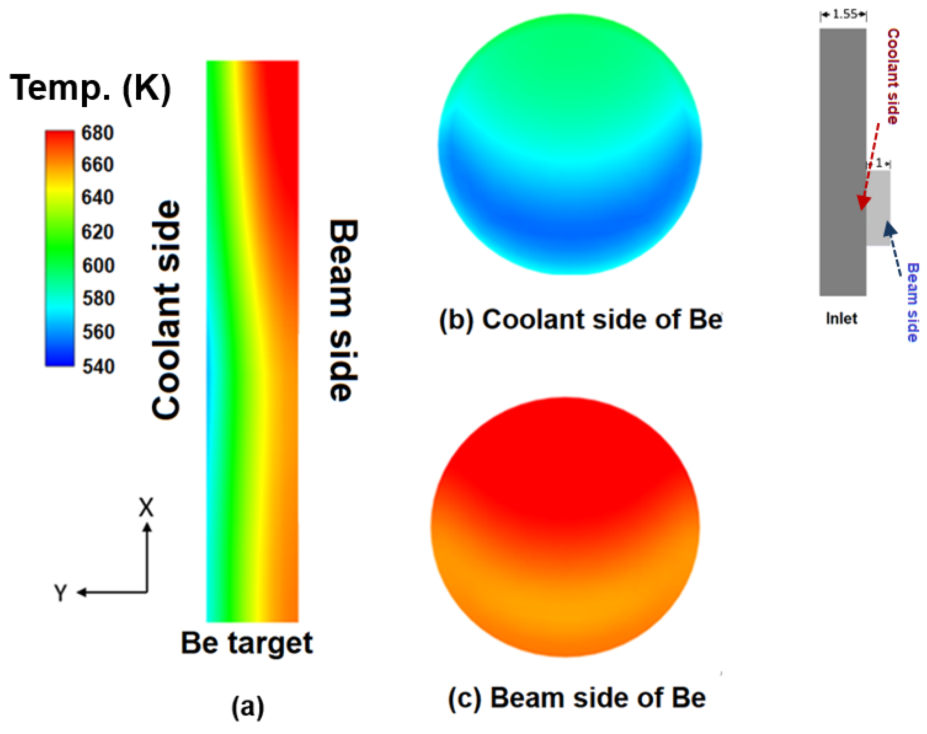
Figure 7 shows the calculated temperature distribution characteristics for the Be target of the AB-BNCT system. Plot (a) displays the temperature contours on the 2D plane taken through the axial central plane of the Be target. The lower temperature distribution is shown near the left side, closer to the coolant. The right side faces the proton beam, resulting in higher temperatures.
Figure 7b,c illustrate the 2D temperature contours on both sides of the Be target. The corresponding explanations for both sides of the Be target are presented in the right portion of this figure. A comparison of these two plots clearly shows that the temperature (ranging from 540 K to 580 K) at the cross-section near the coolant channel is clearly much lower than that (ranging 640 K to 680 K) at the surface facing the beam. In addition, a peak temperature of ~680 K occurs at the surface near to the beam side, and this value is much lower than the melting point (1560 K) [
24] of the Be target. This result confirms that the present thermal management design, using the coolant channel employing the boiling heat transfer mechanism and the preset flow conditions, can efficiently remove the heat (30 kW suggested by Heron Neutron Medical Corp.) deposited in the Be target. The Be target cannot be melted or degraded under this rated heat loading.
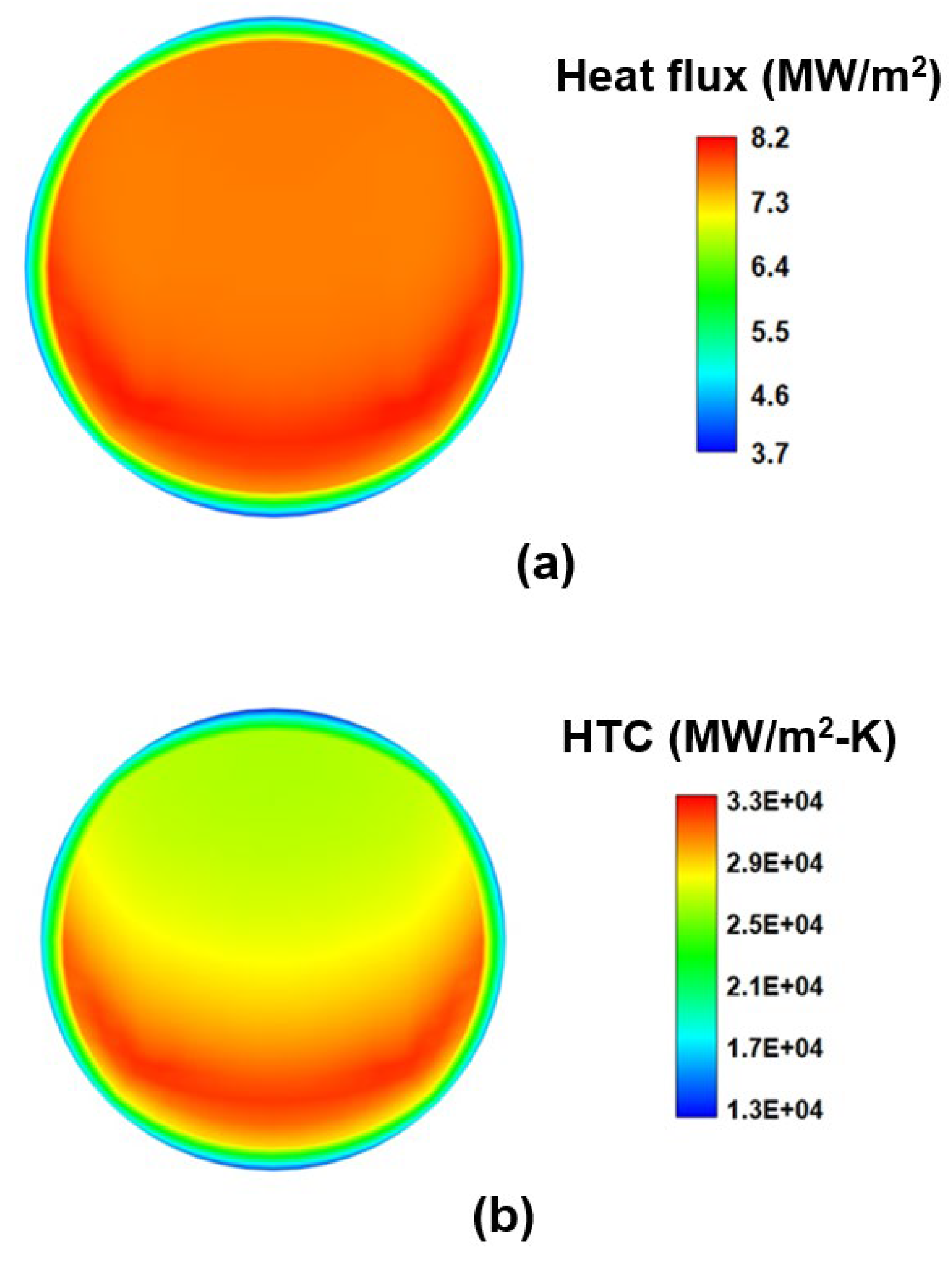
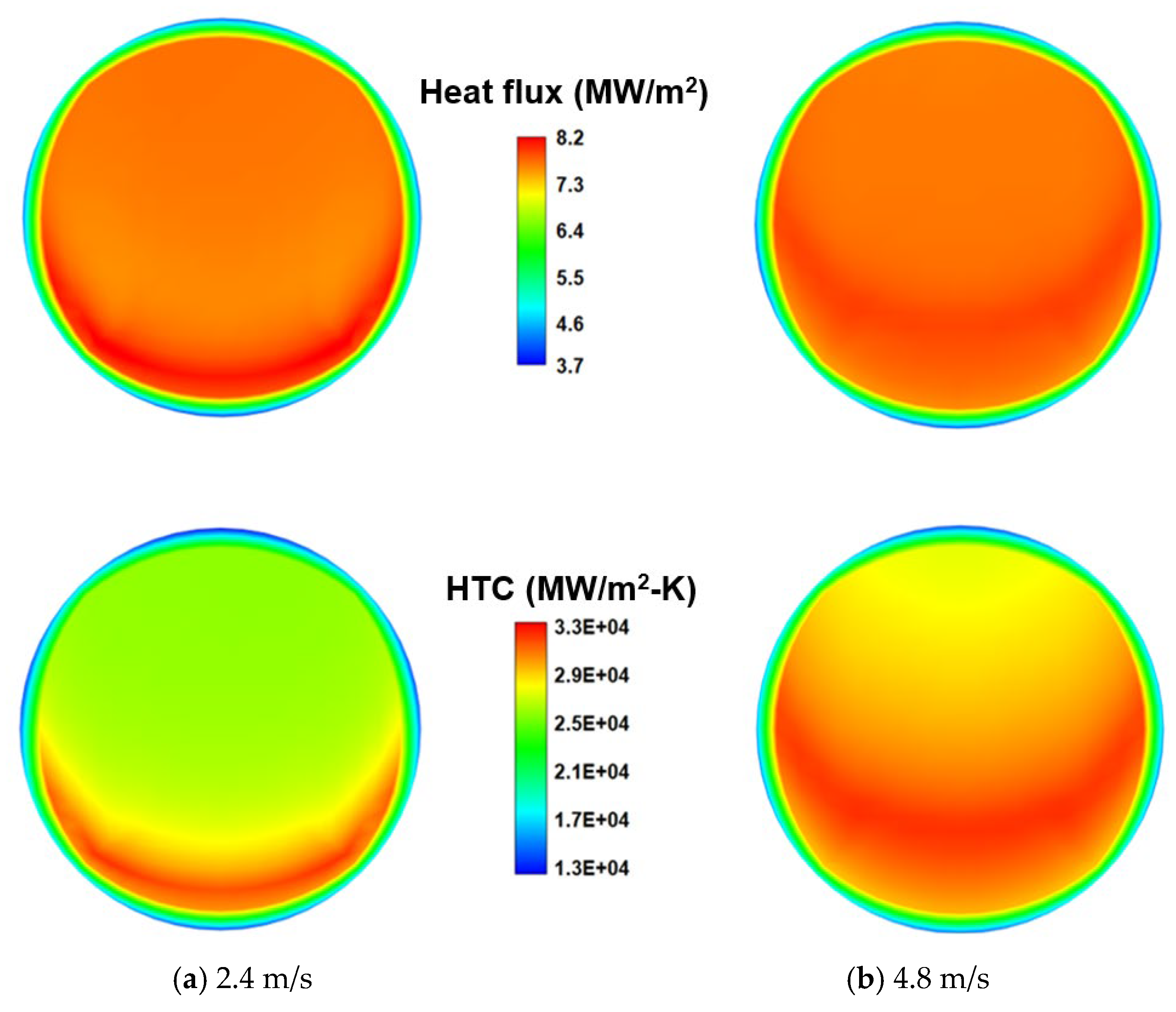
The contours of the calculated wall heat flux and the corresponding heat transfer coefficient (HTC) on the Be target surface facing the coolant are also shown in
Figure 8a,b, respectively. It can be clearly seen in
Figure 8a that the maximum heat flux is about 8.2 MW/m
2, which is much lower than the CHF value (>10 MW/m
2). The HTC of boiling water in the present simulation conditions can reach 2.5~3.3 × 10
4 W/m
2-s. In addition to the higher HTC and lower temperature of the Be target, the boiling heat transfer mechanism can also result in a more uniform heat flux (7~8 MW/m
2) on the target surface. These are the advantages of the boiling heat transfer mechanism applied to thermal management design for the AB-BNCT system.
The effect of the inlet coolant mass flowrate on the thermal management design for the AB-BNCT system is also considered in the present simulation work.
Figure 9 shows the calculated void fraction distributions on the cross-section taken through the central axis of the coolant channel under inlet coolant velocities of 2.4 m/s (Re = 3.43 × 10
5) and 4.8 m/s (Re = 6.86 × 10
5), respectively. The corresponding scales for both the plots can be referred to from the right portion of
Figure 6. The bubbles generated from the target surface are removed more efficiently downward as the inlet coolant velocity increases. The region occupied by the vapor then decreases with the increasing inlet velocity, as revealed when comparing
Figure 6 and
Figure 9. The effect of inlet velocity on the surface temperature distributions of the Be target surface facing the coolant side is shown in
Figure 10, and the corresponding effect on the HTC distributions is also indicated in
Figure 11. Observation of temperature distributions in
Figure 7b and the upper plots of
Figure 10 reveals that the lower-temperature region (blue) on the target surface near the coolant increases with increasing inlet velocity due to higher heat transfer. The higher-temperature region (red) on the surface near the beam (
Figure 7c and the lower plots of
Figure 10) decrease with the increase in the coolant velocity. The higher heat transfer due to the higher inlet velocity is also confirmed in a comparison of HTC for various inlet velocities, as shown when contrasting
Figure 8a with the lower plots in
Figure 11. The HTC region (red) increases as the inlet coolant velocity increases from 2.4 m/s to 4.8 m/s. This higher HTC for the higher inlet velocity results in the lower target temperature, as well as the more uniform heat flux distribution on the target surface. A detailed comparison of
Figure 8b and the upper plots in
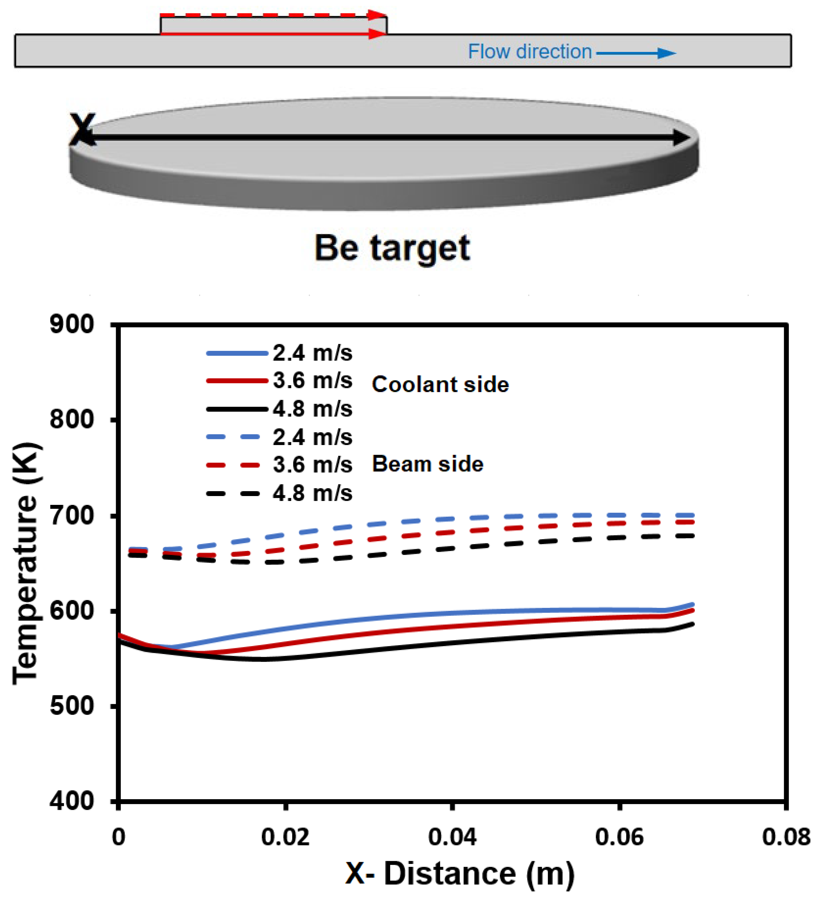
Figure 11 implies a more uniform distribution in surface heat flux for an inlet velocity of 4.8 m/s. However, more pumping power is needed to produce a larger flowrate of cooling water, which also increases the design and operational costs. These are the disadvantages of using a higher coolant flowrate for the thermal management of the AB-BNCT system. The temperature is usually higher in the central region of the Be target. Therefore, the temperature distributions along the central line on both sides of the target can be clearly demonstrated using the line curves (
Figure 12). The abscissa is the distance (x) along this central line, which is schematically illustrated in the upper portion of this figure. The dashed lines represent the temperature distributions on the surface near the beam side, and the solid lines are those on the surface near the coolant side (as indicated in the upper portion). As clearly seen in this figure, the maximum temperature in the target is much lower than the melting point (1560 K) of the Be target under various inlet velocities (mass flowrate), confirming the integrity of the Be target and the capability of the present thermal management design.
However, the deformation of the Be target is another matter of concern for the long-term operation of the AB-BNCT system under the conditions of high proton intensity and high energy deposition. The Be target is generally confined using a circumferential ring in order to fix its position. The expansion of Be in the x–z-direction (as shown in
Figure 3) due to thermal stress is prevented. Thus, the deformation of the Be target is limited to the y-direction (i.e., the vertical direction relative to the disk-shaped Be target). With the temperature distribution in the Be target obtained, its deformation can be evaluated using ANSYS [
20].
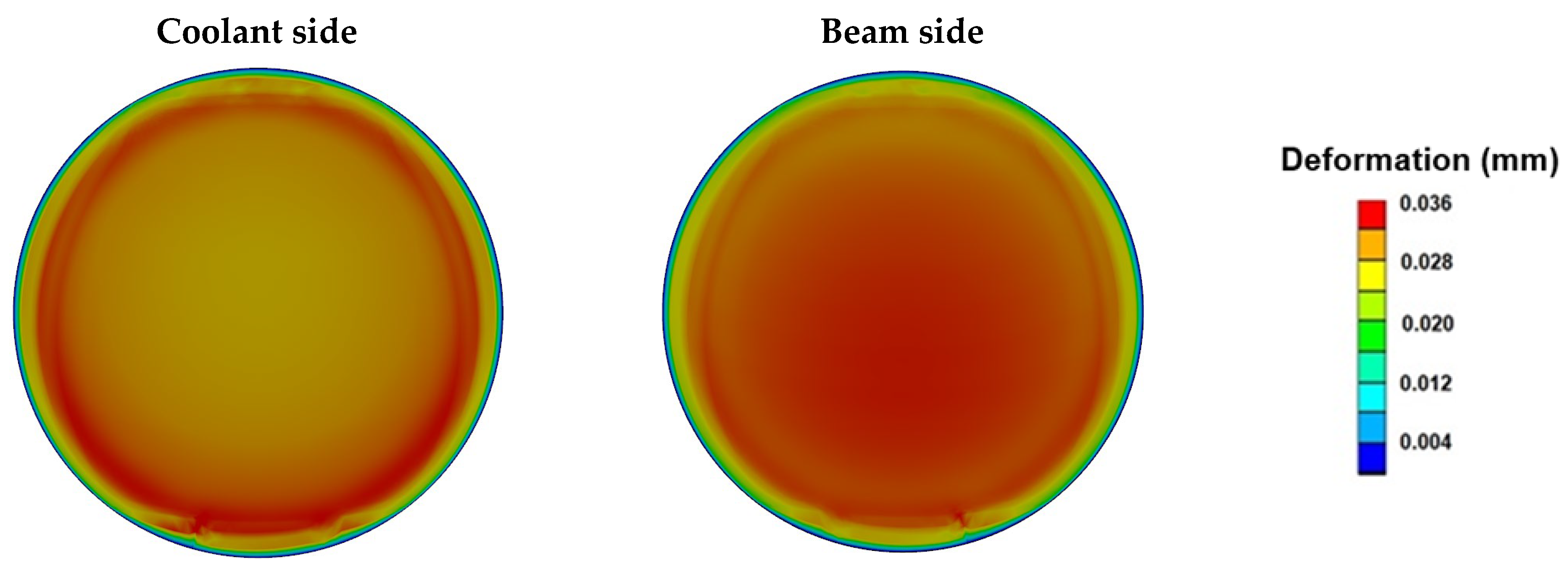
Figure 13 shows the deformation of the Be target on both sides under various values of inlet coolant velocity. This comparison clearly reveals that the target deformation is less severe as the inlet velocity increases (i.e., the heat transfer capability increases). The maximum values of deformation on the beam side of the target are predicted to be 37.64 μm, 36.01 μm, and 34.40 μm for inlet velocities of 2.4 m/s, 3.6 m/s, and 4.8 m/s, respectively. The small amount of thermal deformation for the various inlet coolant velocities also confirms the Be target’s integrity for the AB-BNCT system (30 kW) and the present thermal management design. With increasing beam intensities from the accelerator facility, more heat would be deposited into the Be target of the AB-BNCT system. Therefore, we investigated the effect of the power deposited in the Be target on the peak temperature, and the predicted result is shown in
Figure 14. It is clearly revealed in this figure that the peak temperature of the Be target increases with increasing power. The increasing trend is approximately linear. Through sensitivity calculations of power, the CFD boiling model proposed in this paper demonstrates that increasing neutron production efficiency (i.e., increasing amount of deposited power in the target) would not compromise the integrity of the Be target for reliable long-term operation of the AB-BNCT system. However, if the staff of Heron Neutron Medical Corp. want to obtain a much more powerful neutron source, system pressure must be elevated in order to increase the CHF and ensure that the deposited maximum heat flux is less than the CHF. In addition, under these near-CHF conditions, stable nucleate boiling cannot be maintained, making the present nucleate boiling model no longer applicable.
Thermal management through traditional single-phase convection is also simulated herein. An inlet velocity of 3.6 m/s and a pressure of 4 atm are set. However, a lower inlet temperature (283.15 K) is adopted in order to obtain higher convective heat transfer, resulting in the need for refrigeration equipment to obtain cooling water.
Figure 15 compares the predicted temperature distributions along the central line on both sides of the target between these two cooling mechanisms. The abscissa in this figure also represents the distance (x) along the central line, which is schematically illustrated in the upper portion of
Figure 12. It is clearly seen in this figure that the temperature distributions on both sides of the Be target when employing thermal management through boiling heat transfer are much lower than those using single-phase convection cooling. The corresponding deformation of the Be target under the single-phase cooling mechanism is presented in
Figure 16. The maximum value of deformation is 53.7 μm for single-phase cooling with an inlet velocity of 3.6 m/s, which is much higher than that for boiling heat transfer cooling under the same inlet velocity. A comparison of
Figure 13 and
Figure 16 reveals that deformation of the target when employing thermal management through the boiling heat transfer is much smaller than that using single-phase cooling under the same inlet flowrate. This is one of the main advantages of boiling heat transfer applied in the thermal management of the AB-BNCT system. In order to clearly compare the simulation results of key parameter values under various operating conditions,
Table 3 summarizes these sensitivity calculation results.
