Article

Dynamic Energy Absorption Performance of Titanium Slag Reinforced Concrete: An Experimental and Numerical Simulation-Based Study

1
Key Laboratory of Deep Underground Science and Engineering (Ministry of Education), College of Architecture and Environment, Sichuan University, Chengdu 610065, China
2
China 19th Met Grp Co., Ltd., Chengdu 610031, China
*
Author to whom correspondence should be addressed.
Processes 2025, 13(6), 1877; https://doi.org/10.3390/pr13061877
Submission received: 18 May 2025 / Revised: 4 June 2025 / Accepted: 11 June 2025 / Published: 13 June 2025
(This article belongs to the Section Materials Processes)

Abstract

With growing demands for improved blast resistance in concrete protective structures, developing new concrete materials that combine high toughness, impact resistance, and efficient energy dissipation is essential. This study replaces conventional aggregates with titanium slag and prepares three specimen groups: pure cement mortar (control), cement mortar with large titanium slag particles, and an optimized mix with titanium slag aggregates. Using Split Hopkinson Pressure Bar (SHPB) tests and AUTODYN finite difference simulations, stress-wave absorption and attenuation performance were systematically investigated. Results show that, under identical impact loading rates, the large-particle titanium slag group increased energy absorption by 23.5% compared with the control, while the optimized mix improved by 19.2%. Both groups maintained stable absorption efficiencies across different loading rates. Numerical simulations reveal that the porous titanium slag model attenuated stress waves by approximately 67.9% after passing through three slag layers, significantly higher than the 51.4% attenuation in the non-porous model. This improvement is attributed to multiple wave reflections and interferences caused by a two-order-magnitude difference in the elastic modulus between the slag and air interfaces, creating ring-shaped stress concentrations that disrupt wave propagation and dissipate impact energy. This research provides experimental support and mechanistic insights for titanium slag application in novel blast-resistant concrete.

1. Introduction

In the context of the rapid iteration of military technology, a pronounced contradiction has emerged between the greatly enhanced destructive effectiveness of modern weapons and the safety-protection requirements of special engineering structures [1,2]. As core bearers of both national strategic security and civilian livelihoods, special engineering facilities—such as energy storage hubs, underground transportation networks, and the containment shells of nuclear installations—possess dual attributes of societal operational support and military strategic value, and their safety and stability not only underpin the effective execution of national strategic deployments but also constitute a critical barrier safeguarding the lives and property of the populace [3,4,5]. Against this backdrop, concrete has become the principal material for the protective systems of these special structures due to its moldability, durability, and cost-effectiveness, and its mechanical performance directly determines a facility’s survivability under extreme loading conditions. However, conventional concrete exhibits inherent limitations when resisting blast loads—its energy-absorption mechanisms are weak, it cannot effectively attenuate the kinetic energy generated by explosions, and its capacity for stress-wave mitigation is limited—rendering it prone to large-scale layer-splitting failures that lead to systemic functional collapse or even catastrophic structural failure [6,7]. Therefore, it is crucial to develop new blast-resistant concrete with efficient energy-dissipation mechanisms.
Under the action of explosive impact stress waves, the damage modes of concrete structures in the mid-to-far field are dominated by layer-splitting and spalling failures. The issue of spalling can be alleviated to some extent by increasing the thickness of the protective layer [8,9]; however, fundamentally enhancing the blast resistance of concrete structures requires a thorough investigation of stress-wave propagation characteristics. Conventional concrete exhibits a relatively dense microstructure, causing stress waves generated by explosions to propagate with almost no attenuation, resulting in low energy dissipation [10,11]. When the compressive shock wave produced by an explosion reaches a free surface of the concrete, it is reflected as a tensile wave, which superimposes with the incident stress wave to create a combined tensile stress field [12,13]. Because the tensile strength of concrete is far lower than its compressive strength, this combined tensile stress induces transverse, parallel cracking in regions of stress concentration within the structure [14,15,16]. Moreover, the near-lossless propagation of stress waves leads to the continual accumulation of internal stresses, with new layered cracks forming persistently and causing a precipitous decline in the load-bearing capacity of the concrete. As the stress waves continue to propagate and stresses accumulate, the supporting capacity of various parts of the structure is compromised, ultimately precipitating large-scale collapse [17,18].
Based on the aforementioned failure mechanisms, research on blast-resistant concrete materials is of critical importance and currently focuses on two main technological pathways. The first involves lightweight concrete systems, typically represented by foamed concrete, which utilize foaming agents or gas-producing chemical reactions to generate numerous uniformly distributed air voids within the cement paste, creating a unique, high-porosity structure. By leveraging the scattering and refraction effects of stress waves in porous media, such materials effectively reduce stress wave peak values and minimize energy transmission [19,20]. However, these materials generally exhibit lower compressive strength compared with conventional concrete and are unsuitable for use as primary load-bearing structural elements. In practice, they are often applied as protective overlay layers on existing structures, which increases fabrication and installation costs. Moreover, in scenarios with limited structural thickness, the reflection coefficient of the stress waves increases, intensifying stress concentration effects and exacerbating local damage [21,22,23]. The second approach involves incorporating steel fiber-reinforced aggregates into cement-based materials to produce ultra-high-performance concrete (UHPC). These aggregates suppress crack initiation and propagation through a bridging effect, significantly enhancing the fracture toughness and tensile strength of the concrete [24,25,26,27]. Nevertheless, the addition of steel fibers not only raises material costs and carbon emissions during production but also leads to interfacial failure under high-temperature conditions due to the mismatch in thermal expansion coefficients between the metal and cementitious matrices, resulting in decreased dynamic compressive strength and an imbalance between the static and dynamic mechanical properties [28,29]. Both technological pathways do not fundamentally alter the traditional cement-based concrete system, but rather, enhance blast resistance by optimizing the material structure or adding reinforcing components. Although they can partially achieve stress-wave absorption and attenuation, thereby reducing blast-induced structural damage, they inevitably cause systemic performance deviations that hinder the coordinated optimization of strength, economic efficiency, and environmental adaptability. Therefore, this study starts from the intrinsic component system of concrete to explore new strategies for targeted performance enhancement.
The original constituent system of concrete comprises cement, sand, water, coarse and fine aggregates, and admixtures, among which the physical and chemical properties of the aggregates play a key role in the overall performance of the material. Replacing traditional coarse and fine aggregates in concrete with porous materials of higher mechanical strength can not only ensure the static strength of concrete but also construct a porous structure that facilitates stress-wave scattering and energy dissipation, thereby providing new material design concepts and technical pathways for improving the performance of blast-resistant concrete. In this context, high-titanium slag, a byproduct of high-temperature ilmenite smelting, has attracted widespread attention for its dynamic mechanical regulation mechanism in cement-based materials. Existing studies have shown that the mechanical strength of titanium slag exceeds that of conventional natural aggregates and that it possesses stable chemical properties, making it suitable for use as a construction material in concrete production [30,31]. During the concrete forming and hardening process, the porous structure of titanium slag increases its contact area with the cement paste and enhances the filling volume. Benefiting from its secondary hydration reaction, a high-strength and high-density paste–slag interfacial structure can be formed, thereby improving the mechanical properties of the concrete. This effect and mechanism have been verified and analyzed through scanning electron microscopy (SEM) [32,33,34]. It has been noted that titanium slag exhibits a high specific surface area and porosity; as stress waves propagate through porous materials, the pore interfaces cause reflection and refraction, which attenuate and dissipate the peak values and energy of the stress waves, thus reducing the large-scale structural damage caused by cumulative propagation [35,36]. However, the effects and mechanisms of stress-wave attenuation when titanium slag is incorporated as an aggregate in concrete remain insufficiently studied and theoretically analyzed.
Building on this foundation, this study systematically investigated the performance and mechanisms of titanium slag when used to replace conventional concrete aggregates in cement-based materials in various forms. Split Hopkinson Pressure Bar (SHPB) tests confirmed that the incorporation of titanium slag effectively absorbs stress-wave energy and attenuates stress peaks. Additionally, quantitative analysis demonstrated that concrete specimens with different forms of titanium slag incorporation maintain stable energy absorption efficiency under dynamic filtering effects. Further, two-dimensional numerical modeling using AUTODYN simulated the stress-wave propagation within the titanium slag concrete, enabling the determination of attenuation ratios for various stress wave parameters. The core mechanism of stress-wave attenuation by titanium slag was identified as the presence of residual air within its porous structure, which, due to a significant difference in elastic modulus between the air and slag, causes extensive reflection and dissipation of stress waves during material interface transmission. This research validates a novel blast-resistant concrete design concept based on titanium slag aggregates, confirming that their incorporation endows concrete with stable and effective energy absorption under dynamic filtering. It provides experimental evidence and theoretical support for engineering applications and offers preliminary insights for further optimization of material properties and mechanism studies.

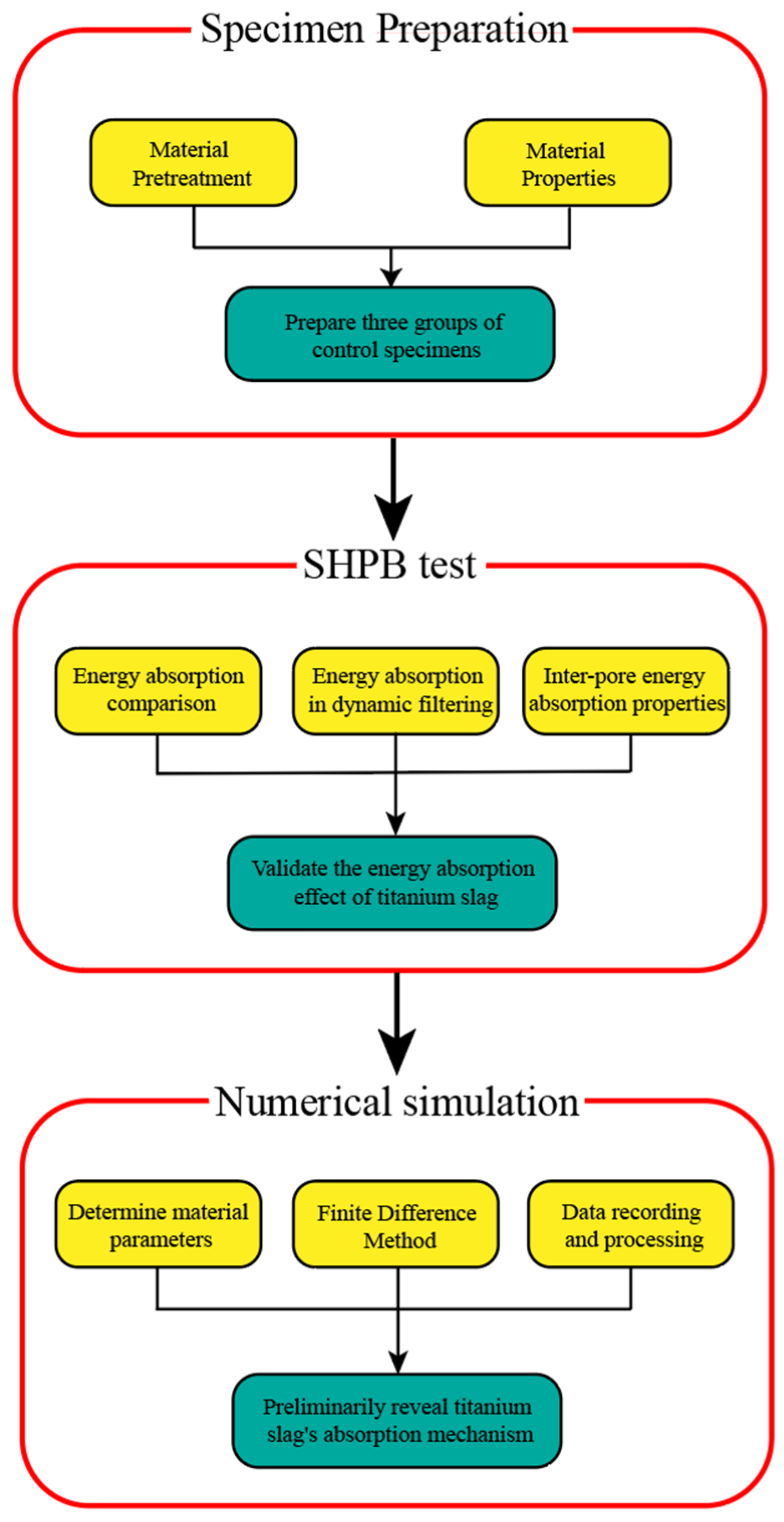
2. Materials and Methods
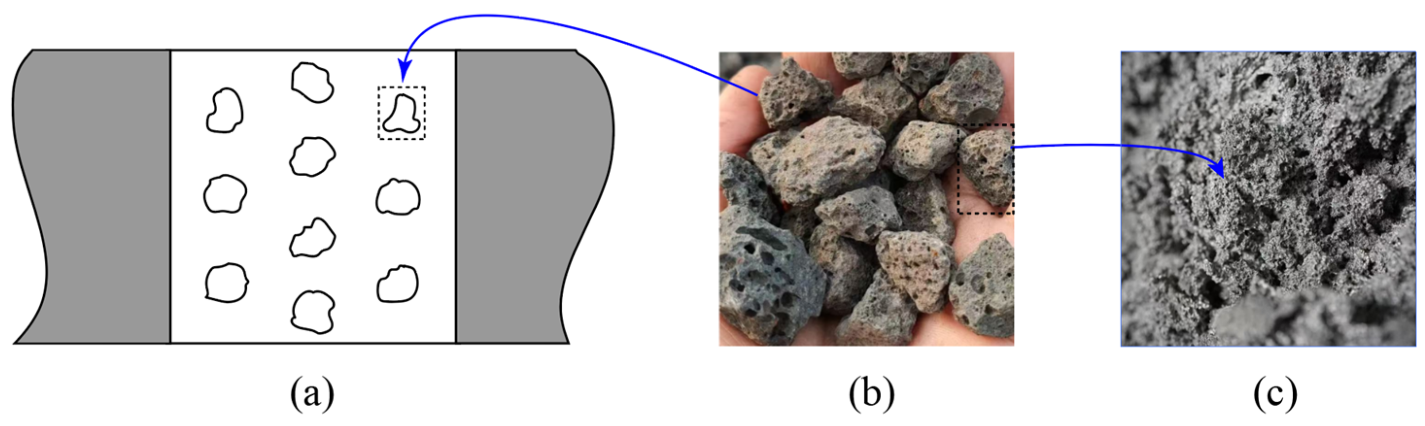
The overall research methodology of this study is illustrated in Figure 1. Titanium slag raw materials were first subjected to manual crushing, screening, and other pretreatment procedures. Based on designed mix proportions, three groups of comparative specimens were prepared: a control group consisting of pure cement mortar, an experimental group incorporating large titanium slag particles, and another group with uniformly distributed titanium slag sand. Using a Split Hopkinson Pressure Bar (SHPB) apparatus, impact tests under identical loading rates were conducted on all three groups. By comparing the results, the enhancement in stress-wave attenuation and energy dissipation due to the incorporation of titanium slag was evaluated. The loading rate was further increased to investigate the energy absorption behavior of titanium slag concrete under dynamic filtering effects. In addition, the energy dissipation characteristics between adjacent slag pore structures were analyzed to further validate the energy-absorbing effect. Numerical simulations were performed using AUTODYN (ANASYS-19.2, Canonsburg, PA, USA), in which a two-dimensional simplified model was constructed based on the experimental parameters. Through processing and analyzing the simulation results, the core mechanism of stress-wave attenuation in titanium slag concrete was preliminarily revealed.

2.1. Materials

2.1.1. Concrete Mix Proportion

In this study, the concrete mix proportions were strictly controlled. Based on existing research on mix design for high-titanium slag concrete, the final mix proportions were determined as shown in Table 1, and specimens from all three groups were prepared following an identical procedure. The CM group consisted of pure cement mortar without any slag and served as the control group to evaluate the improvement in energy absorption resulting from the incorporation of titanium slag. The TC group represented specimens in which large, uncrushed titanium slag particles were added to the cement mortar. These coarse particles retain the inherent high-porosity structure of the slag, allowing for an assessment of the role of pore structure in enhancing energy dissipation in concrete. The TO group represented the optimized mix design, in which titanium slag was incorporated in the form of both coarse and fine crushed aggregates. This approach preserves part of the slag’s porous structure and reflects a practical incorporation method suitable for engineering applications.
The particle size distributions of the titanium slag used in the TC and TO groups were analyzed. The TC group utilized uncrushed large-particle slag with a size range of 30–53 mm and an average of approximately 46 mm. The uniformity coefficient (Cu) was 1.37 and the curvature coefficient (Cc) was 1.02, indicating a relatively narrow and well-graded distribution within the range. In the TO group, the titanium slag sand was manually sieved into fine (5–10 mm) and coarse (10–20 mm) aggregates. The calculated Cu and Cc were 1.58 and 1.19, respectively, also reflecting a concentrated and uniform particle size distribution. Both groups exhibited consistent gradations within defined ranges, with no abnormal dispersion, effectively minimizing the influence of particle size variability on the test results.

2.1.2. Specimen Preparation Process

Figure 2 illustrates the process of specimen preparation and the experimental procedure. The materials used in the experiment are shown in Figure 2a. The cement was P·O42.5R ordinary Portland cement (Shanshui Company, Tainan City, Taiwan); the sand was natural river sand with a particle size range of 0.2 mm to 0.5 mm. To improve the performance of the slurry, a polycarboxylate-based water reducer (Niji Company, Kowloon, Hong Kong) was incorporated, which enhanced the fluidity of the cement mortar. The water used was ordinary tap water. The titanium slag for the experiment was a byproduct of the titanium iron ore smelting process from Pangang Steel Group, which was manually crushed and then sieved into fine aggregates (5 mm to 10 mm) and coarse aggregates (10 mm to 20 mm).
To prevent the blockage of titanium slag aggregates, the raw materials were weighed according to the mix design ratio during the preparation stage and classified into dry and wet materials in advance (Figure 2b). A drum-type mixer (Figure 2c) was selected for mixing. The materials were added in batches: first, the dry materials, composed of cement, sand, and coarse and fine aggregates, were placed into the mixer, followed by dry mixing for 20 s to ensure uniform dispersion of the aggregates. Then, the wet materials, consisting of water and a water-reducing agent, were slowly added, and the mixture was stirred for 100 s to achieve thorough blending. Afterward, the mixture was scooped into molds, and the upper surface was leveled with a metal trowel. The molds were then placed on a vibrating table and vibrated until the mixture no longer collapsed. The specimens were then transferred to a room-temperature environment for several days to allow for solidification and shaping (Figure 2d). Once the surface of the specimens no longer exudes moisture, this indicates the specimen has solidified and formed. At this point, the specimens were demolded using an air gun and transferred to a constant-humidity curing chamber for 28 days of curing. After the curing period, the specimens were removed (Figure 2e). The cured specimens were uniformly polished to ensure that both the incident and transmitted surfaces are flat (Figure 2f). Strain gauges were affixed to the front and rear ends of the concrete specimens, and they were cured with 502 adhesive and plastic film, ready for use in experiments.
Figure 3 illustrates the spatial distribution and morphology of the embedded titanium slag particles in the TC group specimens. Each specimen in the TC group contains three uniformly arranged layers of titanium slag, with each layer consisting of three to four particles (Figure 3a). These titanium slag particles exhibit a distinctive porous structure, characterized by numerous irregularly shaped pores (Figure 3b). A close-up view reveals that the surface of the particles is rough and uneven, with small pores of varying sizes distributed irregularly, further increasing the specific surface area of the structure (Figure 3c).
To gain a more detailed understanding of the physical properties of titanium slag, the water saturation method was employed to determine its porosity using Equation (1). The titanium slag samples were first oven-dried and weighed to obtain their dry mass ( W d r y ). The volume of each sample was then measured using the water displacement method. After fully immersing the samples in water and allowing them to reach saturation, their saturated mass ( W s a t ) was recorded. The porosity was calculated by dividing the difference between the saturated and dry weights by the product of water density and slag volume. Multiple tests showed that the porosity of titanium slag ranged from 37.9% to 44%, with an average value of 41.2%. The density of the titanium slag was calculated by dividing the dry mass by its volume, yielding a value of 2739 k g / m 3 . To ensure the reliability of the data, multiple titanium slag samples were measured, and the average values were used. The physical properties obtained from different samples were highly consistent, with no significant individual variation, indicating that these properties can be considered uniform across all specimens.
ϕ = W s a t W d r y ρ w a t e r × V ,
To investigate the energy absorption characteristics between adjacent pore structures of titanium slag, additional strain gauges were arranged along a vertical line on both the front and rear ends of the TC group specimens, as illustrated in Figure 4. The two strain gauges were positioned on the same vertical axis, with an approximate spacing of 80 mm. The strain gauge at the front end recorded the initial stress wave transmitted from the incident bar to the specimen, while the gauge at the rear end captured the stress wave after attenuation through the three internal layers of titanium slag. By comparing and analyzing the peak values of the stress signals from the front and rear gauges, the dissipation behavior of stress waves between adjacent titanium slag pore structures can be identified.
Due to the use of a 100 mm diameter bar in the Split Hopkinson Pressure Bar (SHPB) device for the Hopkinson bar test, plastic molds with an identical radius (Φ100 mm × 100 mm) were selected to ensure a tight fit between the specimen and the bars of the device, preventing any scattering of the stress waves during propagation. A layer of release agent was applied to the inner surface of the mold, and a cloth was used to wipe it evenly to form a smooth oil film, ensuring easy demolding.

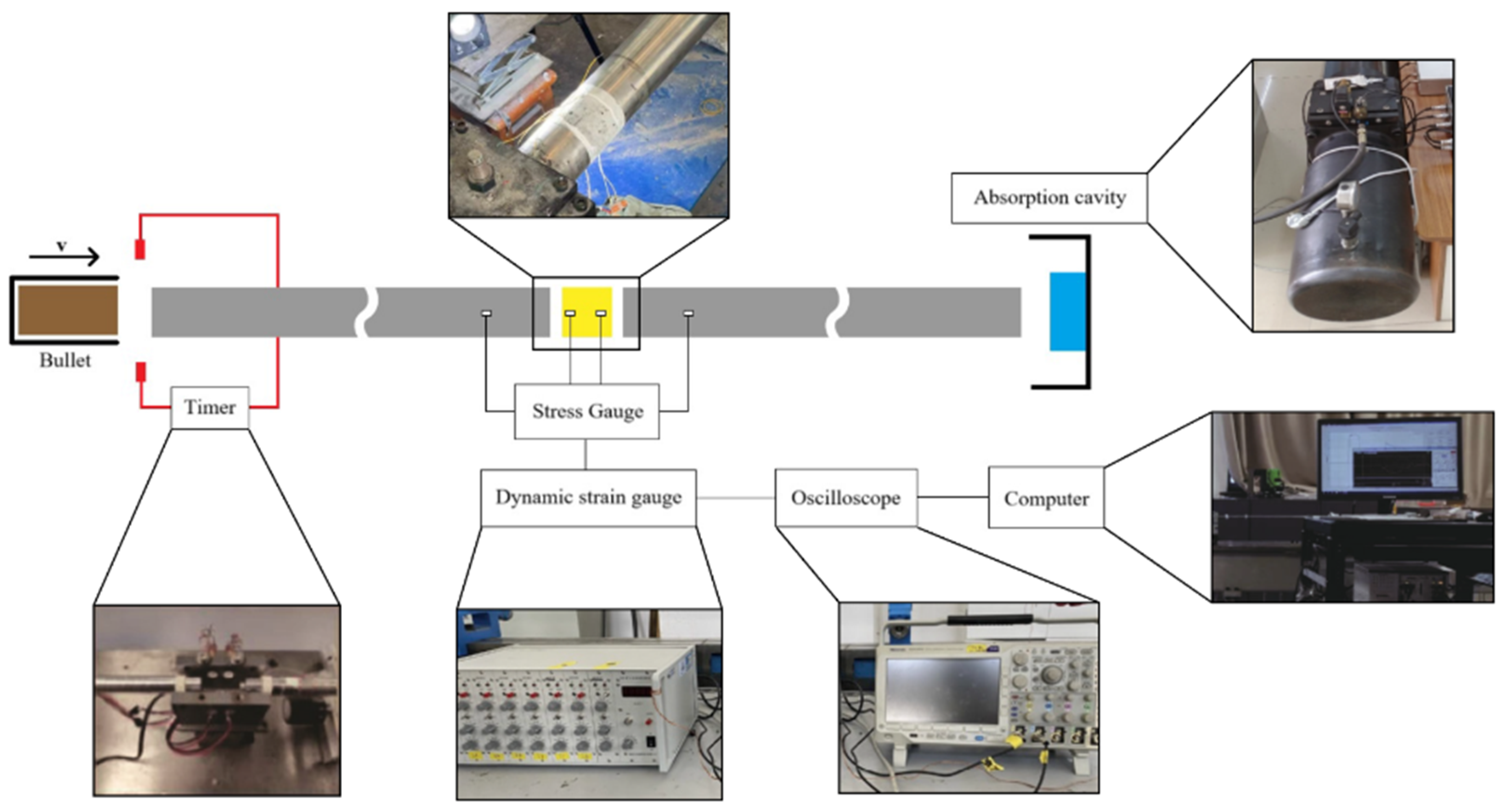
2.1.3. Experimental Apparatus

The SHPB (Split Hopkinson Pressure Bar) apparatus used in the experiment is shown in Figure 5. The system consists of several key components, including the launching device, timer, incident bar, transmission bar, dynamic strain gauges, oscilloscope, computer data processing system, and energy absorption unit. The primary specifications of the apparatus are as follows: Both the incident and transmission bars are made of steel, with a diameter of 100 mm, an elastic modulus of 216 GPa, and a density of 7860 kg/m3. The stress wave propagation velocity between the two bars is 5242 m/s. By adjusting the pressure valve of the gas-driven system, the striker (bullet) can be launched at different velocities to achieve impact tests under various loading rates. When the striker impacts the incident bar, a stress wave is generated and transmitted through the incident bar to the specimen. Part of the stress wave is reflected, forming a reflected wave. After passing through the specimen, the remaining stress wave continues into the transmission bar, generating a transmitted wave. The energy absorption unit at the end prevents the reflected wave from rebounding and interfering with the measurements. Voltage signals from strain gauges installed on both the pressure bars and the specimen are collected and processed through a computer-based data acquisition system.
During an explosion, the strain rate near the detonation point can reach as high as 10 3   S 1 to 10 4   S 1 , often resulting in severe damage to nearby structures. As the stress wave propagates through the structure, it gradually transforms into an elastic wave, and the strain rate attenuates significantly in the far-field region, typically reducing to several tens of S 1 or even lower. In this study, a strain rate range of 10 to 15 S 1 was selected to evaluate the improved stress-wave attenuation and energy absorption performance of titanium slag concrete. This range was intended to simulate the dynamic response of concrete subjected to far-field blast loading conditions.

2.2. Methods

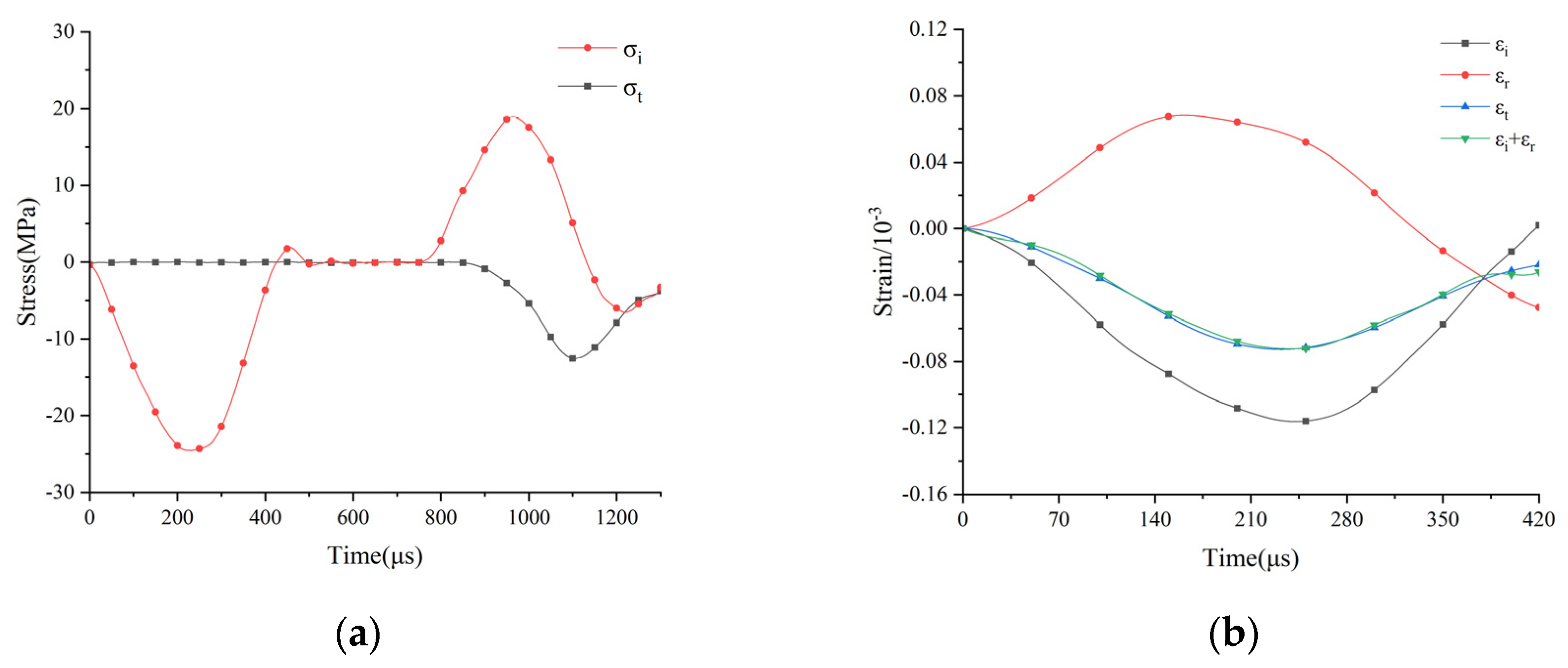
2.2.1. Data Preprocessing

Strain gauges were placed on the incident bar, transmission bar, front end, and rear end of the specimen to collect waveform signal data. The signals collected by the strain gauges are voltage signals. The strain signal can be obtained using Equation (2) below, where U(t) represents the raw voltage signal collected by the strain gauge, V is the bridge voltage, and K is the sensitivity coefficient.
ε t = U ( t ) V K ,
σ t = E ε ( t ) ,
The stress–strain linear constitutive relationship (3) is then used, where E is the elastic modulus of the two bars of the SHPB device, to obtain the stress–time relationship diagram. Figure 6 shows the preliminary data processing and verification. The stress data is smoothed to obtain an example waveform of the concrete specimen during the impact test (Figure 6a). According to the standards for the validity of stress-wave testing data in the “Rock Dynamics Testing Code” (GB/T 50266-2013) [37], stress balance needs to be verified. Based on the three-wave balance theory, the stress wave signal is separated, and the peaks of the incident wave ( σ i ), reflection wave ( σ r ), and transmission wave ( σ t ) are aligned. The superposition waveform of the incident and reflection waves is constructed. The degree of overlap between the sum of the incident and reflection waves and the transmission wave is used to determine if the data satisfies the stress balance (Figure 6b). Similarly, data from each specimen is processed, and it is found that the transmission wave closely matches the superimposed waveform, proving that the test data is valid.
Based on the experimental strain data, the strain rates were calculated using Equation (4). The results show that the strain rate for the TC group ranged from 9.86 to 15.06 S 1 , while that for the TO group ranged from 10.17 to 14.12 S 1 . Within this strain rate range, the specimens remained in the elastic stage, corresponding to the dynamic filtering effect region of the material.
ϵ ˙ t = c L { ϵ o t + ϵ i t + ϵ r t } ,

2.2.2. Energy and Energy Absorption Ratio Calculation

As the carrier of energy, the stress wave is transmitted from the impact device to the incident bar during the initial stage of the impact loading. It then enters the specimen through the bar–specimen interface. During this process, due to the differing material properties at both ends of the interface, part of the incident wave is not effectively transmitted to the specimen, but instead, propagates in the opposite direction within the incident bar as a reflected wave. The remaining energy is absorbed and dissipated within the specimen, and then, transmitted to the transmission bar in the form of a transmitted wave. To quantitatively analyze the dynamic response performance of each specimen to the stress wave, the incident energy, reflected energy, and transmitted energy can be calculated based on the strain signals generated on the incident and transmission bars during the stress wave transmission process, according to Equation (5). The energy absorption rate is then obtained through Equation (6). Here, E represents the elastic modulus of the two bars in the SHPB device, c represents the wave velocity, which can be converted using the elastic modulus and density of the two bars, and A represents the cross-sectional area of the incident and transmission bars of the Φ100 mm SHPB device.
W I t = E A c 0 τ ε I 2 ( t ) d t W R t = E A c 0 τ ε R 2 ( t ) d t W T t = E A c 0 τ ε T 2 ( t ) d t ,
η = W I W R W T W I × 100 % ,

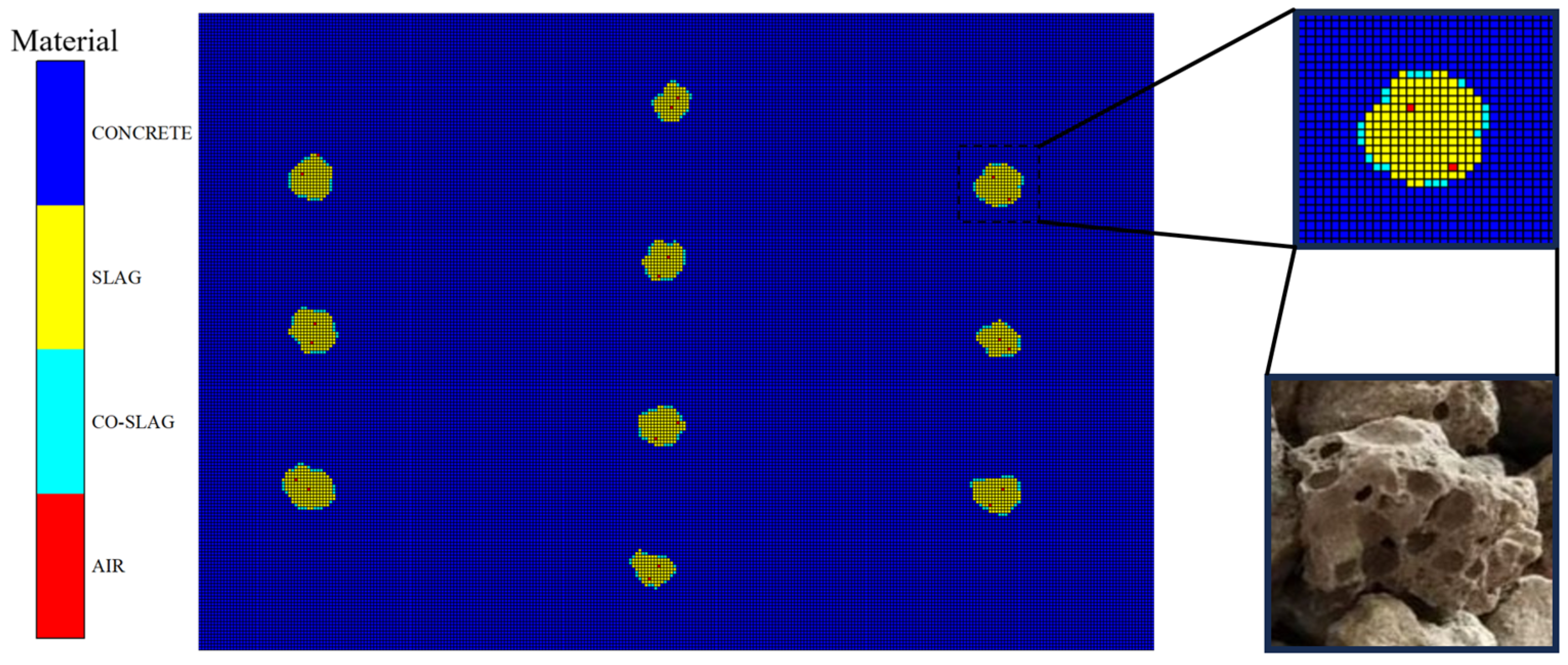
2.2.3. Model Establishment

The numerical simulation was conducted to evaluate the validity of the experimental results and to investigate the mechanism by which titanium slag absorbs and attenuates stress waves. To more intuitively illustrate the propagation of stress waves within the specimen, AUTODYN was employed for numerical simulation. Its explicit dynamic algorithm offers excellent computational stability, and its precise time-step control allows for accurately capturing the model’s transient response characteristics. Additionally, Gaussian points can be configured within the model to collect data from various locations. These features facilitate the investigation of the stress-wave attenuation process and mechanisms in titanium slag concrete, while also providing data support for subsequent quantitative analysis. Based on the internal structure of the TC group, a numerical model incorporating large titanium slag particles was constructed. The model retained the high-porosity structure of the titanium slag and included three uniformly distributed layers of slag particles to analyze the dissipation mechanism of stress waves in a porous medium.
When concrete structures are subjected to explosive impacts, the structure near the detonation point experiences instantaneous high-intensity loads and undergoes catastrophic failure. As the structure in this region is damaged, it absorbs a significant amount of energy, causing a sharp attenuation of the stress wave amplitude. However, as the stress wave propagates further, the degree of material damage gradually decreases, and the attenuation effect weakens significantly. In the medium- and far-field regions, the propagation of the stress wave can be approximated as a non-dissipative elastic wave, where the nonlinear behavior of the concrete can be neglected during this stage [38]. Based on this characteristic, when exploring the mechanism by which titanium slag absorbs stress waves within concrete, the concrete structure can be treated as a linear elastic model, and the explosive stress wave can be approximated as a triangular wave. This wave is converted into boundary conditions and applied to the sides of the model, with a peak value of 15,000 MPa and a total duration of 0.3 ms.
The specimen is simplified into a two-dimensional plane model. After dividing the mesh, different materials are filled in groups to outline the shape of the slag. To simulate the air void structure within the titanium slag, individual mesh cells are assigned inside the slag as “air chambers.” Similarly, the SHPB model is equivalently simplified, with the incident bar and launch device simplified to dynamic stress boundary conditions applied at the left end of the specimen. The transmission bar structure is eliminated, and a transmission boundary is set at the right end of the specimen. The maximum element size of the model is 1.0 mm, with a total of 60,000 elements. The model is shown in Figure 7.
Due to the incorporation of titanium slag, its unique rough and porous surface forms a stronger interface with the cement paste at the point of contact. The strength of this interface is higher than that of the paste and titanium slag, and thus, a new material category needs to be defined [39,40]. Additionally, the titanium slag contains small air chambers that require separate selection of the predefined mesh to model these air chambers. The model is shown in the figure. The materials within the specimen are categorized into cement paste, titanium slag, paste–slag interface, and air. The material equations of state are all linear elastic models, and the specific parameters are provided in Table 2.

3. Results

3.1. SHPB Impact Test Results

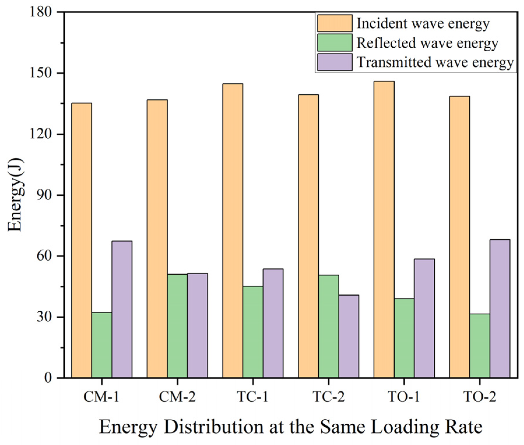
3.1.1. Impact Energy Absorption Characteristics of Titanium Slag Concrete

Impact tests with similar loading rates were conducted on the three groups of specimens to compare their energy absorption performance. The strain gauge signals were processed using Equations (1) and (2), confirming that the loading rates of the three groups were comparable. Based on Equation (3), the incident energy, reflected energy, and transmitted energy were calculated. The corresponding energy data is presented in Figure 8, which shows that the incident energies of all specimens are approximately equal. The energy absorption rate and the peak stress of the incident wave, calculated using Equation (4), are summarized in Table 3. The results reveal that concrete specimens incorporating titanium slag exhibit superior energy absorption performance. Specifically, the TC group achieved an energy absorption rate of 0.3166, representing an approximate 23.05% increase over the average absorption rate of the control group composed of pure cement mortar (CM), indicating that the addition of titanium slag effectively enhances the material’s energy absorption capacity. Likewise, the TO group specimens, in which titanium slag was incorporated as both coarse and fine aggregate, demonstrated an approximately 19.26% increase in average energy absorption rate, further confirming their excellent energy dissipation characteristics. These findings suggest that the inclusion of titanium slag contributes to improved energy dissipation under impact loading by enhancing the attenuation of stress waves, thereby improving the impact resistance of the concrete. This highlights its promising potential for engineering applications.

3.1.2. Dynamic Filtering Effect on Titanium Coarse Concrete Energy Absorption

Figure 9 illustrates the energy absorption performance of concrete specimens containing titanium slag particles under higher impact loading rates. By gradually increasing the air pressure in the impact apparatus, the loading rate applied to the specimens increased progressively, with the calculated incident energy exhibiting a corresponding stepwise increase. The energy absorption rates of the TC group specimens under these conditions, calculated using Equation (4), are presented in Table 4. Despite the increase in loading rate, the energy absorption rates remained stable within the range of 0.3102 to 0.3281, with a coefficient of variation of only 1.91%. To verify the reliability of the energy absorption rate data for the TC group specimens, the Chauvenet’s criterion was applied. The ratio of the deviation of the suspected data to the standard error was calculated as 1.26, which is less than the confidence coefficient t = 1.65. Therefore, it can be concluded that there are no outliers in this data set. No significant correlation between energy absorption rate and loading rate was observed, indicating that the incorporation of titanium slag allows the concrete specimens to maintain stable energy absorption performance under the dynamic filtering effect, demonstrating good adaptability to varying loading rates.

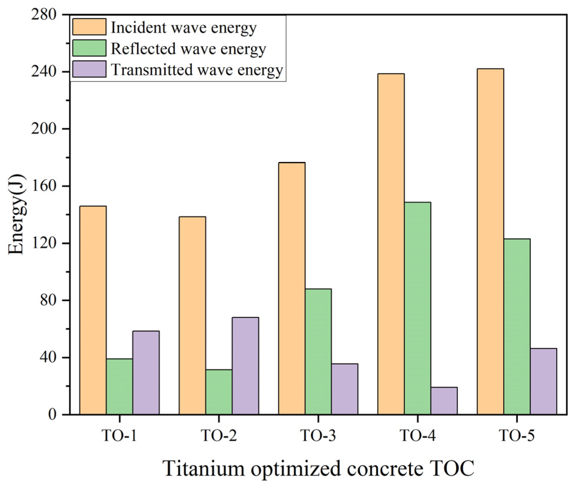
3.1.3. Energy Absorption of Titanium-Optimized Concrete Under Different Loading Rates

This further verifies the energy-absorption performance of titanium slag-optimized concrete under different loading rates. The energy absorption performance of titanium slag aggregate concrete was evaluated under higher loading rates by similarly increasing the air pressure of the impact apparatus. Under these testing conditions, the energy distribution of each component was calculated using the same method, as shown in Figure 10, and the corresponding energy absorption rates for the concrete are presented in Table 5. The energy absorption rates of the TO group specimens ranged from 0.2815 to 0.3322, with a coefficient of variation of 5.94%. Similarly, the TO group data was verified using Chauvenet’s criterion. The ratio of the deviation of the suspected data to the standard error was 1.649, which is slightly less than the confidence coefficient t = 1.65. Therefore, the fluctuations in the energy absorption rate of this group are considered to be within the normal range, with no outliers present. Overall, the absorption rates remained stable and showed no significant correlation with the loading rate, indicating that the concrete exhibited good adaptability under the dynamic filtering effect.
An analysis of variance (ANOVA) was performed on the energy absorption rates of the CM, TC, and TO groups. The F-value between the CM and TC groups was 117.4, indicating a significant difference in energy absorption performance between the two. The F-value between the CM and TO groups was 7.8, also suggesting a notable difference in their energy absorption behavior. These results verify that the incorporation of titanium-bearing slag significantly alters the energy absorption capacity of concrete. Additionally, t-tests were conducted on the three groups. The t-value between the CM and TC groups was 12.1, indicating a statistically significant difference at the 99.99% confidence level. The t-value between the CM and TO groups was 4.2, which also denotes a significant difference at the 99% confidence level. These results further demonstrate that the inclusion of titanium-bearing slag leads to considerable changes in the energy absorption performance of concrete.

3.1.4. Energy Absorption Characteristics Between Adjacent Slag Pores

During the impact testing process, in order to clarify the energy absorption characteristics between adjacent titanium slag hierarchical structures, additional strain gauges were installed on the front and rear ends of the specimen in addition to those placed on the incident and transmission bars. The front and rear strain gauges were aligned along the same vertical axis, with a spacing of approximately 80 mm, to investigate the attenuation behavior of the stress waves during their propagation within the specimen. The collected data was processed using Equations (1) and (2), and the typical dynamic response curves are shown in Figure 11. Compared with the rear-end strain gauge, the front-end gauge detected the stress wave earlier and recorded a higher strain amplitude. In contrast, the strain signal captured by the rear-end gauge—after passing through the titanium slag concrete—exhibited a significantly reduced peak value. This result indicates that the porous structure of the titanium slag effectively attenuates the peak stress of the wave, thereby providing a protective effect for the structural material.
The data were quantitatively analyzed to determine the peak attenuation of the stress wave after propagating approximately 80 mm within the specimen. Using Equations (3) and (4), the energy absorption rate of the specimen with respect to the stress wave was calculated and is presented in Table 6.

3.2. Numerical Simulation Results

3.2.1. Finite Difference Simulation of Titanium Slag Concrete

The stress amplitude of the stress wave at different moments inside the specimen is shown in Figure 12. At t = 0.3112 ms (Figure 12a), when the loading is completed, the stress wave presents a typical triangular waveform with a peak value of 15 MPa. At t = 0.3963 ms (Figure 12b), the stress wave enters the titanium slag aggregate and begins to affect the internal “air chamber” structure. Due to the two-order-magnitude difference in elastic modulus between the slag and air, stress waves at the slag–air interface undergo reflection and transmission, forming a stress concentration zone where the reflected and transmitted waves intersect. This leads to individual stress concentration units and low-stress gaps. At t = 0.4717 ms (Figure 12c), the stress wave peaks pass through the titanium slag aggregate. Due to the cancellation effect of the reflected wave, a stress void appears around the air chamber structure, and the stress amplitude surrounding it is much lower than the peak of the stress wave. At t = 0.6118 ms, the stress wave has completely passed through the first layer of titanium slag, forming a distinct stress attenuation zone behind the air chamber (Figure 12d). Subsequently, a portion of the reflected wave still exhibits residual oscillations, diffusing in the opposite direction of the incident wave (Figure 12e). Finally, after propagating through three layers of titanium slag, the peak of the stress wave is significantly reduced, and the waveform shows obvious dispersive characteristics (Figure 12f). The attenuation of the stress wave is closely related to the air chamber structure within the titanium slag, as shown by the results of the numerical simulation.
Five Gaussian points were placed before and after each titanium slag layer, with a total of four columns. This arrangement was used to detect the gradual attenuation of the stress wave as it propagated through the specimen. The layout of the Gaussian points is shown in Figure 13.
Since the stress wave propagates in the x-direction, representative x-stress and x-velocity data was collected. The data from the five Gaussian points in each column were averaged to serve as the representative values. As shown in Figure 14a, the peak value of x-velocity data gradually attenuates after passing through the titanium slag layers. The attenuation in the first two layers is around 35%, while the attenuation in the third layer is 24.2%. Compared with the initial data collected from the first column of Gaussian points, the x-velocity in the last column is reduced to only 32.1%. The attenuation pattern of x-stress is similar, with a 35% reduction in the first two layers and a 23.1% reduction in the third layer, resulting in a final residual stress of 32.9% in that direction (Figure 14b). The attenuation patterns of velocity and stress are highly consistent, indicating that the stress wave is effectively dissipated within the specimen, achieving excellent attenuation results.

3.2.2. Finite Difference Simulation of Titanium Slag Concrete Without Air Voids

To verify that the titanium slag’s ability to absorb and attenuate stress waves primarily relies on the air chambers, we employed a control variable method by removing the air chamber structure and filling the air units with titanium slag material. The evolution of the stress wave within the specimen was recalculated, as shown in Figure 15. Compared with the two-order-magnitude difference in elastic modulus between the paste and air, the elastic modulus between the paste and titanium slag, as well as the interface, fluctuates by only about 11%, resulting in a significant reduction in the amplitude of the reflected wave. At t = 0.4806 ms, when the stress wave begins to contact the first layer of titanium slag, no effective stress concentration zone is formed at the material interface (Figure 15a). Additionally, due to the similar elastic modulus of the materials, the transmission rate of the stress wave is increased, and no distinct stress attenuation zone is formed behind the titanium slag. After passing through the first layer of titanium slag, the attenuation effect is not significant (Figure 15b); meanwhile, the attenuation effect of the stress wave is less pronounced after passing through the model (Figure 15c). This confirms that the residual air within the porous structure of the titanium slag provides an interface with a large elastic modulus difference, which is the key factor enabling it to attenuate and absorb stress waves.
The model without the air chamber structure used the same Gaussian point array layout, and recorded x-stress and x-velocity data. The results show that the peak values of the data also decrease progressively, but the attenuation is smaller than that in the model with the air chamber structure (Figure 16). Specifically, the x-velocity experiences an attenuation of 28.4% after the first layer of titanium slag, 21.1% after the second layer, and only 14.0% after the third layer. The final velocity peak retains 48.6% of the initial value from the first layer (Figure 16a). For x-stress, the attenuation after the first layer of titanium slag is 28%, 20.8% after the second layer, and 13.6% after the third layer. The final stress peak still retains 49.2% (Figure 16b). Compared with the model with the air chamber structure, the attenuation in this control group is reduced by approximately 16%, resulting in a 24.29% decrease in attenuation efficiency, which verifies that the air chamber structure in titanium slag plays an important role in the attenuation of stress waves.

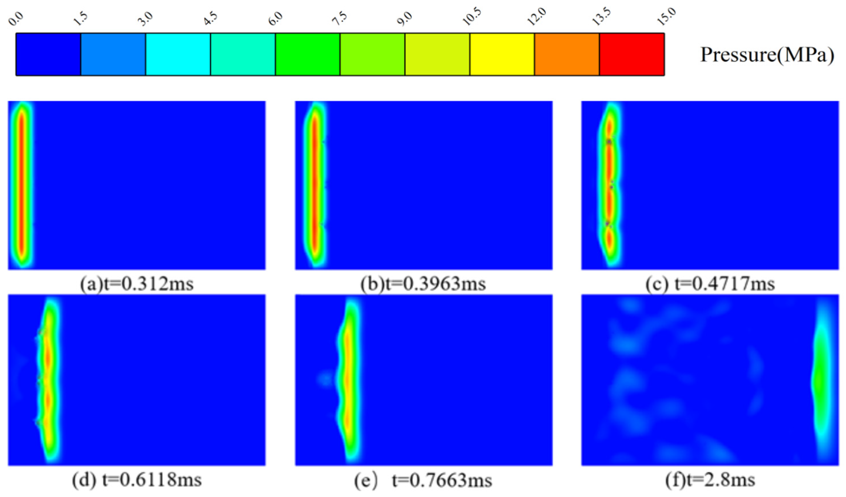
3.2.3. FDM Simulation of Single Slag Particle Response

By reducing the AUTODYN calculation time step, we focused on the entire process of interaction between a single titanium slag particle and the stress wave (Figure 17a). This allowed us to observe more clearly that when the stress wave propagates and contacts the air chamber structure (Figure 17b), a significant portion of the stress wave is reflected. These reflected waves overlap with the original stress wave, forming a ring-shaped stress concentration zone around the slag particles, which then begins to spread outward. Subsequently, when the air chamber structure enters the peak region of the stress wave (Figure 17c), the surrounding stress value can reach 22 MPa, which is nearly half of the original peak stress. Meanwhile, due to the expansion of the stress concentration zone, the original stress waveform is disturbed, and localized waveform distortion occurs. After the stress wave passes through the air chamber structure (Figure 17d), there are still some residual reflected waves around the air chamber. These secondary waves not only disturb and scatter the original stress wave, but also dissipate some of the stress wave’s energy.
To record the amplitude variation in the stress wave as it interacts with the slag layer and to verify the mechanism by which titanium slag particles attenuate the stress wave, a Gaussian point array was arranged before and after the slag, as shown in Figure 18.
The x-direction stress and x-velocity data for the Gaussian points on the front side (Points 1, 2, 3) and the rear side (Points 4, 5, 6) of the titanium slag were compared. In the figure, the solid lines represent the Gaussian points on the front side of the titanium slag (Points 1, 2, 3), while the dashed lines represent the Gaussian points on the rear side of the titanium slag (Points 4, 5, 6). A larger velocity peak is observed on the front side of the titanium slag, while the velocity peaks on the rear side are effectively reduced by the slag layer (Figure 19a). After the primary stress wave passes, velocity oscillations are still detected by the Gaussian points, and these fluctuations are due to waveform disturbances caused by secondary waves propagating in the reverse direction. Figure 19b shows the stress–time curves along the x-direction. Compared with the front side of the titanium slag, the stress values experienced by the Gaussian points on the rear side are effectively reduced, demonstrating the role of the titanium slag in attenuating the stress wave and protecting the structure. Similar oscillations are also detected by the Gaussian points.

4. Discussion

There has been considerable progress in the study of porous materials for wave absorption, as their low density, high specific surface area, and cellular structure significantly enhance the ability to absorb various types of waves [41,42,43,44,45]. Numerous studies have also investigated the improvement in the energy absorption performance of concrete through the incorporation of porous materials [46,47]. Han et al. [48] utilized the low impedance characteristic of the synthetic material expandable polystyrene (EPS) by incorporating it into a cement matrix as a lightweight aggregate. Given that EPS consists largely of air and has low density, EPSC specimens with varying densities were prepared by adjusting the dosage, and their impact energy absorption capacities were systematically validated. Wang et al. [49] introduced aluminum powder into cement paste, leveraging the chemical reaction between aluminum powder, calcium hydroxide, and water to generate hydrogen gas, thereby creating a cellular structure within the specimens. These specimens were then autoclaved to produce autoclaved aerated concrete (AAC), with varying densities controlled by different aluminum powder contents, and the energy absorption efficiency under different incident energy levels was evaluated. Zhang et al. [50] replaced conventional fine aggregate with coral sand—ground from natural coral agglomerates—to prepare coral aggregate seawater concrete (CASC). The coral sand exhibited a porosity of 48.3%, significantly higher than traditional fine aggregates. Additionally, polypropylene fibers were added to enhance specimen toughness, and the energy dissipation characteristics of the composite under different incident energies were examined. Ma et al. [19] added a high-efficiency foaming agent, capable of expanding approximately 30 times, into cement paste. The agent generated fine foams with a density of only 35 kg/m3. By adjusting the ratio of foaming agent to cement paste, foam concrete specimens of different densities were fabricated, and their energy absorption behaviors under various strain rates were investigated. Feng et al. [51,52] employed 27.5% industrial hydrogen peroxide as a chemical foaming agent, which decomposed naturally to form uniformly distributed pores within the specimens. These pores were subsequently fixed through gelation, and foam concretes of varying densities were prepared by adjusting the mix proportions. Similarly, Ma et al. [53] used coral as coarse aggregate and coral sand as fine aggregate to produce CASC, and conducted Split Hopkinson Pressure Bar tests to determine the energy absorption ratio under different incident energy gradients. In this study, titanium slag—a byproduct of perovskite smelting from Panzhihua Iron and Steel Company—was used as aggregate in two forms: large particles and a combination of coarse and fine aggregates mixed into cement paste to fabricate test specimens. As an artificial industrial byproduct, titanium slag exhibits stable chemical properties and excellent mechanical performance, making it an ideal material for construction applications. Its porous structure provides high porosity, contributing to the enhancement of the energy absorption performance of concrete [54,55]. The energy absorption ratios obtained from selected studies were compiled and are presented in Figure 20. As shown in Figure 20, the EPS concrete (EPSC) prepared by Han et al. [48] exhibits a generally consistent energy absorption ratio under the dynamic filtering effect, demonstrating good adaptability. However, its energy absorption performance falls short of expectations, failing to effectively attenuate and absorb the incident wave energy. The autoclaved aerated concrete (AAC) developed by Wang et al. [49] shows a relatively high energy absorption ratio under low incident energy, but this ratio decreases significantly with increasing incident wave energy. The coral aggregate seawater concrete (CASC) studied by Zhang et al. [50] demonstrates a high level of energy absorption and maintains stability under the dynamic filtering effect. The foamed concrete fabricated by Feng et al. [51,52] performs poorly in terms of energy absorption under low incident energy, and its absorption performance exhibits considerable instability under the dynamic filtering effect. Similarly, the CASC prepared by Ma et al. [53] shows a wide fluctuation in energy absorption performance under the same conditions. In contrast, the concrete specimens containing titanium slag developed in this study exhibit a relatively high energy absorption ratio and good adaptability to varying levels of incident energy.
The existing principles for preparing porous concrete materials can be broadly categorized into two types. The first involves generating a large number of uniformly distributed air voids within the cement paste, a process that can be achieved using foaming agents or gas-producing chemical reactions followed by gelation fixation and autoclave curing to form a solid concrete matrix [56,57,58]. The second method involves incorporating porous materials directly into the cement paste, treating the paste as a binder, whereby the high porosity of the aggregate contributes to increasing the overall porosity of the concrete. Porous materials used as aggregates come from diverse sources, including human-made porous materials such as slag and expandable polystyrene (EPS) [59,60,61,62] as well as natural porous materials like discarded oyster shells and shale [63,64,65]. Foam concrete produced by the void-generation method generally exhibits a decrease in compressive strength as the foam density decreases, and its compressive strength is typically lower than that of conventional concrete. Therefore, fibers are often added to enhance its mechanical properties [21,66]. Under impact loading, if the strain rate is low, the cellular structure of the foam concrete collapses, leading to irreversible volumetric compaction along the stress wave propagation direction. During the densification process of the foam structure, energy is absorbed through plastic deformation, and splitting cracks are formed [47,67]. If the strain rate induced by the load is high, diagonal shear failure may occur, forming inclined cracks that penetrate the specimen along its diagonal. At sufficiently high strain rates, the specimen undergoes complete failure, disintegrating in a brittle manner into fragments and dust. For porous concrete made by incorporating porous aggregates, certain aggregates—due to their porous structure—can enhance the hydration reaction with the cement paste and form a composite structure with porous morphology, thereby improving the overall strength of the concrete. Consequently, this type of concrete can be used as a primary structural material in construction facilities [39]. When subjected to high-impact loads, microcracks initially form on the loaded surface and then propagate into the cement paste regions segmented by the aggregates. The porous structure guides the crack paths such that most cracks deflect along the edges of the aggregates and form intersections within the paste blocks, while only a few cracks pass through the aggregates themselves. Ultimately, the intersecting cracks cause the specimen to disintegrate into fragments of sizes comparable to the aggregates [68,69].
Due to the relatively limited static mechanical performance of foam concrete, it is often employed as a sacrificial cladding layer rather than as a primary structural component in building structures requiring blast and explosion resistance. When subjected to explosive or other impact loads, the sacrificial layer is severely damaged and absorbs a substantial amount of energy, thereby protecting the integrity of the internal structure [70]. The implementation of layered foam concrete structures can effectively isolate non-sacrificial structural elements from blast effects, significantly enhancing the blast resistance of the protected structure compared with unprotected configurations. Upon failure of the sacrificial layer, the peak value of the explosion-induced stress wave is markedly reduced, thereby mitigating damage to the internal components [71,72,73]. Additionally, the pronounced acoustic impedance gradient between the sacrificial layer and the protected structure results in greater energy reflection at the interfacial boundaries during blast wave transmission across layers. This further intensifies the damage to the sacrificial layer while concurrently reducing the energy transmitted to the protected structure [74,75]. Benefiting from its excellent deformability, foam concrete is also applied in engineering fields that require accommodation of large deformations, such as tunnel support systems and railway subgrades, where it can absorb considerable deformation without failure. This helps alleviate stress concentrations within the structure, thereby ensuring its long-term operational stability [76,77]. Concrete incorporating porous aggregates demonstrates static strength comparable to that of conventional concrete and is suitable for use in load-bearing structural elements. Furthermore, its mechanical strength remains stable over the service time, indicating excellent durability [78,79]. Owing to its dual functions of energy absorption and load-bearing capacity, porous aggregate concrete can fulfill structural performance requirements while offering effective energy dissipation, making it suitable for applications in safety-critical and impact-resistant engineering scenarios such as underground protective structures and transportation infrastructure [80,81,82]. Additionally, this type of concrete exhibits superior freeze–thaw and corrosion resistance compared with conventional concrete, making it particularly well suited for deployment in cold regions and coastal areas where high resistance to environmental degradation is required. Such properties contribute to significantly extending the service life of building structures [83,84]. Taking titanium-bearing slag concrete as an example, compared with ordinary slag, titanium-bearing slag contains higher levels of chloride salts, which can accelerate clinker hydration in the early stages, thereby enhancing early strength [85]. Due to its low reactivity and slower response, the amount of silicate involved in hydration is limited, which helps suppress the formation of alkali–silica gel. This gel tends to swell upon water absorption, leading to cracking and structural degradation [86,87]. Furthermore, the accelerated early hydration contributes to a denser pore structure, effectively blocking the ingress of external moisture, chlorides, and sulfates. This delay in steel corrosion and other deterioration processes improves the long-term durability of the concrete [88]. Compared with traditional aggregates, which require mining, crushing, screening, and transportation, the use of titanium slag avoids the mining phase and its associated procedures such as site selection and government approvals. Natural aggregates are typically obtained through river excavation or mountain blasting, which not only damages the environment but also incurs taxes like the Resource Tax and Environmental Protection Tax—up to CNY 15 per ton according to the Resource Tax Law of the People’s Republic of China. Additionally, extraction requires large machinery, leading to further energy and maintenance costs. In contrast, titanium slag is an industrial solid waste that accumulates in large quantities at disposal sites. It involves no mining costs and is often available at minimal or no charge. However, long-term stockpiling incurs land use and management expenses. Recycling titanium slag thus provides a more economical and environmentally friendly alternative. In some regions, such as Panzhihua in Sichuan Province, its utilization is further supported by local policy incentives.

5. Conclusions

This study investigated the positive effect of incorporating titanium slag as an aggregate on the energy absorption and attenuation performance of concrete under stress-wave impact. Three groups of specimens with varying amounts and forms of titanium slag incorporation were prepared and subjected to impact testing using a Split Hopkinson Pressure Bar (SHPB) apparatus. The experimental results were validated, and the mechanism of titanium slag’s influence was analyzed through AUTODYN numerical simulations. The main conclusions are as follows:
Under the same impact loading rate, concrete containing titanium slag particles (TC group) exhibited a 23.05% increase in the energy absorption rate compared with the ordinary cement mortar (CM group), while the optimized mix design with titanium slag aggregate concrete (TO group) showed a 19.26% increase. Multiple tests conducted at elevated loading rates revealed coefficients of variation in energy absorption of only 1.91% for the TC group and 5.94% for the TO group, demonstrating excellent adaptability to varying loading rates.
The peak stress of the stress wave attenuated by 14.3% after propagating laterally 80 mm within the TC group specimen. Assuming elastic wave propagation, the corresponding stress wave energy attenuation was calculated to be 26.53%, which aligns well with the SHPB test data considering the actual specimen dimensions. This indicates that the incorporation of titanium slag effectively reduces the peak stress of the stress wave, a trend also confirmed by finite difference numerical simulations.
A numerical model of the TC group specimen was constructed and simulated. Gaussian points were placed before and after the titanium slag layer, showing a stepwise attenuation of stress and particle velocity along the stress wave propagation direction, with residual variables remaining at approximately 32.5% of their initial values. When the air units were removed from the model using a controlled variable approach, the attenuation efficiency decreased by approximately 24.29%.
The core mechanism by which titanium slag attenuates stress waves lies in the residual air trapped within its porous structure. Due to the significant difference in elastic modulus between air and slag, a substantial portion of the stress wave is reflected at the material interfaces. The superposition of reflected and incident waves generates stress concentration zones and, following the air units, forms stress attenuation bands that effectively dissipate and weaken the stress waves.
This study has demonstrated that the incorporation of titanium slag can effectively enhance the performance of concrete in terms of stress-wave absorption and energy dissipation. A preliminary analysis of its underlying mechanisms was also conducted through numerical simulation. However, the experimental scope regarding the replacement ratios of titanium slag was relatively limited, which constrains a comprehensive understanding of its energy-absorbing behavior. Moreover, the study lacks microscopic characterization of the titanium slag, such as scans of its morphology, and thus lacks experimental evidence to reveal its reinforcement mechanisms at the microstructural level. Future research will focus on expanding the range of titanium slag replacement ratios and systematically evaluating its influence on the dynamic performance of concrete. In addition, advanced microstructural characterization techniques such as scanning electron microscopy (SEM) will be employed to investigate the relationship between pore structure and mechanical behavior. The dynamic response under different loading rates will also be considered to provide more comprehensive theoretical support and data foundation for the engineering application of titanium slag in blast-resistant concrete.

Author Contributions

Conceptualization, W.G. and M.W.; methodology, S.W., Y.L. and M.W.; software, S.W. and H.S.; validation, H.L., H.S., X.Z., Y.L. and W.G.; formal analysis, H.L., Y.L. and M.W.; investigation, S.W., H.L., X.Z., Y.L. and W.G.; resources, M.W. and W.G.; data curation, H.S. and Y.L.; writing—original draft preparation, S.W.; writing—review and editing, W.G.; visualization, S.W.; supervision, M.W. and W.G.; project administration, W.G.; funding acquisition, M.W. All authors have read and agreed to the published version of the manuscript.

Funding

This research was funded by the National Natural Science Foundation of China (12272247). Supported by Sichuan Communication Surveying & Design Institute Co., Ltd. (No. 232023001).

Data Availability Statement

Due to the need for confidentiality in part of this study, the test data and numerical simulation model cannot be made public.

Conflicts of Interest

Author Yuqin Luo was employed by the company China 19th Met Grp Co., Ltd. The remaining authors declare that the research was conducted in the absence of any commercial or financial relationships that could be construed as a potential conflict of interest.

References

  1. Shu, Y.; Wang, G.; Lu, W.; Chen, M.; Yan, P.; Wang, Y. Stability Assessment Method of Damaged Concrete Gravity Dams Subjected to Penetration Explosion. Eng. Struct. 2022, 267, 114683. [Google Scholar] [CrossRef]
  2. Gao, Z.; Wang, Z.; Chen, Y.; Li, S.; Li, L.; Chen, L.; Huang, C.; Yang, Q. Study on the Damage Effect of 12.7 Mm Armour Piercing Incendiary Projectile Penetrating Aramid Reinforced Concrete Slab. Comput. Struct. 2025, 312, 107706. [Google Scholar] [CrossRef]
  3. Shu, Y.; Wang, G.; Lu, W.; Chen, M.; Lv, L.; Chen, Y. Damage Characteristics and Failure Modes of Concrete Gravity Dams Subjected to Penetration and Explosion. Eng. Fail. Anal. 2022, 134, 106030. [Google Scholar] [CrossRef]
  4. Anas, S.M.; Alam, M.; Umair, M. Reinforced Cement Concrete (RCC) Shelter and Prediction of Its Blast Loads Capacity. Mater. Today Proc. 2023, 74, 547–568. [Google Scholar] [CrossRef]
  5. Huang, X.; Yue, Y.; Zhu, B.; Chen, Y. Failure Analysis of Underground Concrete Silo under Near-Field Soil Explosion. Tunn. Undergr. Space Technol. 2024, 147, 105696. [Google Scholar] [CrossRef]
  6. Zhao, C.; Wang, Q.; Lu, X.; Wang, J. Numerical Study on Dynamic Behaviors of NRC Slabs in Containment Dome Subjected to Close-in Blast Loading. Thin-Walled Struct. 2019, 135, 269–284. [Google Scholar] [CrossRef]
  7. Liu, J.; Wei, J.; Li, J.; Su, Y.; Wu, C. A Comprehensive Review of Ultra-High Performance Concrete (UHPC) Behaviour under Blast Loads. Cem. Concr. Compos. 2024, 148, 105449. [Google Scholar] [CrossRef]
  8. Li, J.; Wu, C.; Hao, H.; Liu, Z. Post-Blast Capacity of Ultra-High Performance Concrete Columns. Eng. Struct. 2017, 134, 289–302. [Google Scholar] [CrossRef]
  9. Yan, J.; Liu, Y.; Yan, J.; Yan, Z.; Xu, Y.; Gao, C.; Huang, F. Collapse of Concrete Target Subjected to Embedded Explosion of Shelled Explosive. Eng. Fail. Anal. 2024, 161, 108298. [Google Scholar] [CrossRef]
  10. Gao, C.; Kong, X.; Fang, Q. Experimental and Numerical Investigation on the Attenuation of Blast Waves in Concrete Induced by Cylindrical Charge Explosion. Int. J. Impact Eng. 2023, 174, 104491. [Google Scholar] [CrossRef]
  11. Li, X.; Miao, T.; Liu, T.; Chen, R.; Yu, A. Acoustic Emission Evaluation and Localization Correction of Concrete Damage Considering Stress Levels. Case Stud. Constr. Mater. 2025, 22, e04281. [Google Scholar] [CrossRef]
  12. Foglar, M.; Hajek, R.; Fladr, J.; Pachman, J.; Stoller, J. Full-Scale Experimental Testing of the Blast Resistance of HPFRC and UHPFRC Bridge Decks. Constr. Build. Mater. 2017, 145, 588–601. [Google Scholar] [CrossRef]
  13. Wang, G.; Shu, Y.; Lu, W.; Chen, M.; Pan, X.; Lu, A. Damage Prediction of Concrete Gravity Dams Subjected to Penetration Explosion. Eng. Fail. Anal. 2023, 143, 106855. [Google Scholar] [CrossRef]
  14. Li, J.; Wu, C.; Hao, H. Investigation of Ultra-High Performance Concrete Slab and Normal Strength Concrete Slab under Contact Explosion. Eng. Struct. 2015, 102, 395–408. [Google Scholar] [CrossRef]
  15. Zhu, W.; Yang, C.; Yin, T.; Jia, J.; Yu, J.; Song, J. Blast Resistant Performance and Damage Mechanism of Steel Reinforced Concrete Beams under Contact Explosion. Eng. Struct. 2024, 315, 118472. [Google Scholar] [CrossRef]
  16. Kang, G.; Zhang, Y.; Xie, X.; Gu, W. Investigation of Blasting Effects and Mechanisms on Concrete Frustums under Side-Contact Explosions. Def. Technol. 2025, S2214914725000807. [Google Scholar] [CrossRef]
  17. Gao, Z.; Chen, Y.; Wang, Z.; Li, S.; Wei, W.; Huang, C. Study on the Failure Effect of Aramid Reinforced Concrete Slab under Localized Blast Loading. Structures 2024, 63, 106292. [Google Scholar] [CrossRef]
  18. Wang, J.; Xu, Y.; Wang, S.; Zhang, W.; Ji, X.; Zhang, B. Effect of High-Strength Rebar and Ultra-High-Performance Concrete on Blast Resistance of Slabs under Contact Explosion Loads. Int. J. Impact Eng. 2025, 198, 105230. [Google Scholar] [CrossRef]
  19. Ma, K.; Ren, F.; Huang, H.; Yang, X.; Zhang, F. Experimental Investigation on the Dynamic Mechanical Properties and Energy Absorption Mechanism of Foam Concrete. Constr. Build. Mater. 2022, 342, 127927. [Google Scholar] [CrossRef]
  20. Liu, X.; Huang, F.; Zheng, A. Investigation of Foam Concrete’s Mechanical Properties and Multi-Scale Damage Evolution Characteristics under Uniaxial Loading. Constr. Build. Mater. 2024, 430, 136503. [Google Scholar] [CrossRef]
  21. Ramamurthy, K.; Kunhanandan Nambiar, E.K.; Indu Siva Ranjani, G. A Classification of Studies on Properties of Foam Concrete. Cem. Concr. Compos. 2009, 31, 388–396. [Google Scholar] [CrossRef]
  22. Yang, Y.; Kong, X.; Fang, Q. Non-Dimensional Analysis on Blast Wave Propagation in Foam Concrete: Minimum Thickness to Avoid Stress Enhancement. Def. Technol. 2023, 36, 30–46. [Google Scholar] [CrossRef]
  23. Falliano, D.; De Domenico, D.; Ricciardi, G.; Gugliandolo, E. Experimental Investigation on the Compressive Strength of Foamed Concrete: Effect of Curing Conditions, Cement Type, Foaming Agent and Dry Density. Constr. Build. Mater. 2018, 165, 735–749. [Google Scholar] [CrossRef]
  24. Das, N.; Nanthagopalan, P. State-of-the-Art Review on Ultra High Performance Concrete—Ballistic and Blast Perspective. Cem. Concr. Compos. 2022, 127, 104383. [Google Scholar] [CrossRef]
  25. Richardson, A.; Coventry, K.; Lamb, T.; Mackenzie, D. The Addition of Synthetic Fibres to Concrete to Improve Impact/Ballistic Toughness. Constr. Build. Mater. 2016, 121, 612–621. [Google Scholar] [CrossRef]
  26. Xu, J.; Wu, C.; Xiang, H.; Su, Y.; Li, Z.-X.; Fang, Q.; Hao, H.; Liu, Z.; Zhang, Y.; Li, J. Behaviour of Ultra High Performance Fibre Reinforced Concrete Columns Subjected to Blast Loading. Eng. Struct. 2016, 118, 97–107. [Google Scholar] [CrossRef]
  27. Yi, N.-H.; Kim, J.-H.J.; Han, T.-S.; Cho, Y.-G.; Lee, J.H. Blast-Resistant Characteristics of Ultra-High Strength Concrete and Reactive Powder Concrete. Constr. Build. Mater. 2012, 28, 694–707. [Google Scholar] [CrossRef]
  28. Li, H.; Chen, W.; Hao, H. Performance of Reinforced Concrete Slabs Subjected to Simultaneous Fire and Blast Loads. Eng. Struct. 2024, 311, 118133. [Google Scholar] [CrossRef]
  29. Zheng, R.; Gao, G.; Yu, Z.; Wang, B.; Zhou, A.; Song, Q.; Bao, J. Dynamic Mechanical Properties of Fiber-Reinforced Lightweight Aggregate Concrete Exposed to High Temperature. J. Build. Eng. 2025, 103, 112161. [Google Scholar] [CrossRef]
  30. Huang, S.; Wang, K.; Wang, H.; Lv, L.; Zhang, T.; Tang, W.; Zou, Z.; Tang, S. Comprehensive Utilization of Titanium-Bearing Blast Furnace Slag by H2SO4 Roasting and Stepwise Precipitation. Chin. J. Chem. Eng. 2025, 80, 24–37. [Google Scholar] [CrossRef]
  31. Wang, W.; Li, X.; Shen, J.; Zhu, H.; Wang, J. Feasibility of High Titanium Heavy Slag Used as Aggregates for Asphalt Mixtures. J. Clean. Prod. 2023, 411, 137332. [Google Scholar] [CrossRef]
  32. Venkataramu, V.; Reddy, B.V.V. Properties of Concrete with Processed Granulated Blast-Furnace Slag as Fine Aggregate. Proc. Inst. Civ. Eng. Constr. Mater. 2024, 178, 1–16. [Google Scholar] [CrossRef]
  33. Xiaoying, L.; Jun, L.; Zhongyuan, L.; Li, H.; Jiakun, C. Preparation and Properties of Reactive Powder Concrete by Using Titanium Slag Aggregates. Constr. Build. Mater. 2020, 234, 117342. [Google Scholar] [CrossRef]
  34. Wang, J.; Li, J.; Lu, Z.; Hou, L.; Li, X.; Zhang, C.; Li, R.; Deng, Y.; Zheng, X. Hydration and Performances of Ordinary Portland Cement Containing Metakaolin and Titanium Slag. Constr. Build. Mater. 2024, 415, 135056. [Google Scholar] [CrossRef]
  35. Liu, G.; Zhang, C.; Zhang, S.; Guo, C.; Liu, S.; Li, M.; Wu, Y. Effect and Mechanism of Calcination on Improving the Hydration Activity of Titanium Extraction Slag. Constr. Build. Mater. 2024, 447, 138144. [Google Scholar] [CrossRef]
  36. Zhu, S.; Hu, J.; Zhang, C.; Li, S.; An, N. Study on Optimization and Mechanism of Mechanical Activation Process of Titanium-Bearing Blast Furnace Slag. J. Mater. Res. Technol. 2022, 19, 3130–3144. [Google Scholar] [CrossRef]
  37. GB/T 50266-2013; Standard for Test Methods of Engineering Rock Mass. Ministry of Housing and Urban-Rural Development of the People’s Republic of China: Beijing, China, 2013. (In Chinese)
  38. Fan, L.F.; Wong, L.N.Y.; Ma, G.W. Experimental Investigation and Modeling of Viscoelastic Behavior of Concrete. Constr. Build. Mater. 2013, 48, 814–821. [Google Scholar] [CrossRef]
  39. Zhang, J.; Wang, M.; Sun, J. Mechanical Behavior and Fracture Mechanisms of High-Strength Concrete Incorporating Porous Titanium Slag Aggregate. J. Mater. Res. Technol. 2025, 36, 6075–6087. [Google Scholar] [CrossRef]
  40. Cibelli, A.; Ferrara, L.; Di Luzio, G. A Combined Numerical and Experimental Study on the Mechanical Aging of High Slag Content High Performance Concrete. J. Build. Eng. 2024, 98, 111294. [Google Scholar] [CrossRef]
  41. Baoyi, L.; Yuping, D.; Yuefang, Z.; Shunhua, L. Electromagnetic Wave Absorption Properties of Cement-Based Composites Filled with Porous Materials. Mater. Des. 2011, 32, 3017–3020. [Google Scholar] [CrossRef]
  42. Xie, S.; Ji, Z.; Yang, Y.; Hou, G.; Wang, J. Electromagnetic Wave Absorption Enhancement of Carbon Black/Gypsum Based Composites Filled with Expanded Perlite. Compos. Part B Eng. 2016, 106, 10–19. [Google Scholar] [CrossRef]
  43. Saleem, M.H.; Abdul-Hamead, A.A.; Othman, F.M. Effect of Furnace Slag on the Electromagnetic Shielding Properties of Fiber Reinforced Concrete. Mater. Today Proc. 2022, 52, 582–587. [Google Scholar] [CrossRef]
  44. Si, T.; Xie, S.; Ji, Z.; Ma, C.; Wu, Z.; Wu, J.; Wang, J. Synergistic Effects of Carbon Black and Steel Fibers on Electromagnetic Wave Shielding and Mechanical Properties of Graphite/Cement Composites. J. Build. Eng. 2022, 45, 103561. [Google Scholar] [CrossRef]
  45. Zhou, C.; Yuan, M.; Di, X.; Qiu, S.; Liang, M.; Luo, Y.; Zou, H. Tunable 1T-Phase MoS2/CNT Reinforced Carbon Foams for Enhanced Low-Frequency Electromagnetic Wave Absorption. Chem. Eng. J. 2025, 512, 162574. [Google Scholar] [CrossRef]
  46. Lu, S.; Xu, J.-Y.; Bai, E.-L.; Luo, X. Effect of Particles with Different Mechanical Properties on the Energy Dissipation Properties of Concrete. Constr. Build. Mater. 2017, 144, 502–515. [Google Scholar] [CrossRef]
  47. Nian, W.; Subramaniam, K.V.L.; Andreopoulos, Y. Experimental Investigation on Blast Response of Cellular Concrete. Int. J. Impact Eng. 2016, 96, 105–115. [Google Scholar] [CrossRef]
  48. Han, J.; Fan, H. Dynamic Properties of Low-Density Expandable Polystyrene Concrete Materials. Def. Technol. 2025, 43, 94–108. [Google Scholar] [CrossRef]
  49. Wang, B.; Chen, Y.; Fan, H.; Jin, F. Investigation of Low-Velocity Impact Behaviors of Foamed Concrete Material. Compos. Part B Eng. 2019, 162, 491–499. [Google Scholar] [CrossRef]
  50. Zhang, H.; Zheng, S.; Li, X.; Pan, L.; Cao, Z.; Shuai, B.; Shen, C.; Zhao, Z. Impact Splitting Tensile Properties and Microstructural Analysis of Polypropylene Fiber Reinforced Coral Seawater Concrete. Constr. Build. Mater. 2025, 471, 140747. [Google Scholar] [CrossRef]
  51. Feng, S.; Zhou, Y.; Wang, Y.; Lei, M. Experimental Research on the Dynamic Mechanical Properties and Damage Characteristics of Lightweight Foamed Concrete under Impact Loading. Int. J. Impact Eng. 2020, 140, 103558. [Google Scholar] [CrossRef]
  52. Feng, S.; Zhou, Y.; Li, Q.M. Damage Behavior and Energy Absorption Characteristics of Foamed Concrete under Dynamic Load. Constr. Build. Mater. 2022, 357, 129340. [Google Scholar] [CrossRef]
  53. Ma, H.; Yue, C.; Yu, H.; Mei, Q.; Chen, L.; Zhang, J.; Zhang, Y.; Jiang, X. Experimental Study and Numerical Simulation of Impact Compression Mechanical Properties of High Strength Coral Aggregate Seawater Concrete. Int. J. Impact Eng. 2020, 137, 103466. [Google Scholar] [CrossRef]
  54. Otoo, S.L.; Shi, Z.; Li, Q.; Wu, Y.; Lai, G.; Amu-Darko, J.N.O.; Deng, C.; Li, S.; Chen, W. Utilization of Titanium Slag in Cement Grout for Gamma Radiation Shielding: Hydration, Microstructure, Mechanical Properties and Gamma-Ray Attenuation Performance. Constr. Build. Mater. 2023, 402, 133031. [Google Scholar] [CrossRef]
  55. Zhang, S.; Yang, H.; Xu, G.; Cui, G. Review on Utilization of Ti-Bearing Blast Furnace Slag from the Past Decade: Whole-Component Utilization and Ti Component Recovery. Chem. Eng. J. 2025, 514, 163115. [Google Scholar] [CrossRef]
  56. Narayanan, N.; Ramamurthy, K. Microstructural Investigations on Aerated Concrete. Cem. Concr. Res. 2000, 30, 457–464. [Google Scholar] [CrossRef]
  57. Panesar, D.K. Cellular Concrete Properties and the Effect of Synthetic and Protein Foaming Agents. Constr. Build. Mater. 2013, 44, 575–584. [Google Scholar] [CrossRef]
  58. Lei, M.; Liu, Z.; Wang, F. Review of Lightweight Cellular Concrete: Towards Low-Carbon, High-Performance and Sustainable Development. Constr. Build. Mater. 2024, 429, 136324. [Google Scholar] [CrossRef]
  59. Chen, C.; Chen, X. Experimental Study of Fracture Damage Characteristics in Steel Slag Porous Concrete Based on Acoustic Emission Technique. Constr. Build. Mater. 2024, 456, 139127. [Google Scholar] [CrossRef]
  60. Lang, L.; Duan, H.; Chen, B. Properties of Pervious Concrete Made from Steel Slag and Magnesium Phosphate Cement. Constr. Build. Mater. 2019, 209, 95–104. [Google Scholar] [CrossRef]
  61. Zhang, L.; Huang, M.; Yang, F.; Zhang, W. A Novel Hydrophilic Modification Method of EPS Particles: Conception Design and Performances in Concrete. Cem. Concr. Compos. 2023, 142, 105199. [Google Scholar] [CrossRef]
  62. Zhu, Y.; Rong, Z.; Jiang, Q.; Shi, J. Influence Mechanisms of Porous Aggregate Morphology, Maximum Size and Optimized Gradation on Ultra-High Performance Concrete with Ferrochrome Slag. Cem. Concr. Compos. 2025, 157, 105890. [Google Scholar] [CrossRef]
  63. Kong, J.; Cong, G.; Ni, S.; Sun, J.; Guo, C.; Chen, M.; Quan, H. Recycling of Waste Oyster Shell and Recycled Aggregate in the Porous Ecological Concrete Used for Artificial Reefs. Constr. Build. Mater. 2022, 323, 126447. [Google Scholar] [CrossRef]
  64. Kuo, W.-T.; Wang, H.-Y.; Shu, C.-Y.; Su, D.-S. Engineering Properties of Controlled Low-Strength Materials Containing Waste Oyster Shells. Constr. Build. Mater. 2013, 46, 128–133. [Google Scholar] [CrossRef]
  65. Zhang, X.; Lu, J.; Poon, C. Enhanced Performance and Sustainability of Foam Concrete Through Shale Aggregate Integration. Constr. Build. Mater. 2025, 479, 141442. [Google Scholar] [CrossRef]
  66. Narayanan, N.; Ramamurthy, K. Structure and Properties of Aerated Concrete: A Review. Cem. Concr. Compos. 2000, 22, 321–329. [Google Scholar] [CrossRef]
  67. Zhou, H.; Wang, Y.; Wang, X.; Zhao, Z.; Ma, G. Energy Absorption of Graded Foam Subjected to Blast: A Theoretical Approach. Mater. Des. 2015, 84, 351–358. [Google Scholar] [CrossRef]
  68. Agar Ozbek, A.S.; Pedersen, R.R.; Weerheijm, J.; Van Breugel, K. Mesoscopic Modeling of the Impact Behavior and Fragmentation of Porous Concrete. Cem. Concr. Compos. 2019, 102, 116–133. [Google Scholar] [CrossRef]
  69. Agar Ozbek, A.S.; Weerheijm, J.; Schlangen, E.; Van Breugel, K. Dynamic Behavior of Porous Concretes under Drop Weight Impact Testing. Cem. Concr. Compos. 2013, 39, 1–11. [Google Scholar] [CrossRef]
  70. Chica, L.; Alzate, A. Cellular Concrete Review: New Trends for Application in Construction. Constr. Build. Mater. 2019, 200, 637–647. [Google Scholar] [CrossRef]
  71. Ma, G.W.; Ye, Z.Q. Analysis of Foam Claddings for Blast Alleviation. Int. J. Impact Eng. 2007, 34, 60–70. [Google Scholar] [CrossRef]
  72. Guruprasad, S.; Mukherjee, A. Layered Sacrificial Claddings under Blast Loading Part I—Analytical Studies. Int. J. Impact Eng. 2000, 24, 957–973. [Google Scholar] [CrossRef]
  73. Guruprasad, S.; Mukherjee, A. Layered Sacrificial Claddings under Blast Loading Part II—Experimental Studies. Int. J. Impact Eng. 2000, 24, 975–984. [Google Scholar] [CrossRef]
  74. Zhou, H.; Ren, H.; Yi, Z.; Wu, X.; Nie, X.; Zhang, H. Anti-Blast Performance of Multilayer Protective Structure with Different Sacrificial Claddings. Eng. Fail. Anal. 2025, 171, 109336. [Google Scholar] [CrossRef]
  75. Kostopoulos, V.; Kalimeris, G.D.; Giannaros, E. Blast Protection of Steel Reinforced Concrete Structures Using Composite Foam-Core Sacrificial Cladding. Compos. Sci. Technol. 2022, 230, 109330. [Google Scholar] [CrossRef]
  76. Wu, K.; Shao, Z.; Qin, S. A Solution for Squeezing Deformation Control in Tunnels Using Foamed Concrete: A Review. Constr. Build. Mater. 2020, 257, 119539. [Google Scholar] [CrossRef]
  77. Tan, X.; Chen, W.; Liu, H.; Chan, A.H.C.; Tian, H.; Meng, X.; Wang, F.; Deng, X. A Combined Supporting System Based on Foamed Concrete and U-Shaped Steel for Underground Coal Mine Roadways Undergoing Large Deformations. Tunn. Undergr. Space Technol. 2017, 68, 196–210. [Google Scholar] [CrossRef]
  78. Oren, O.H.; Gholampour, A.; Gencel, O.; Ozbakkaloglu, T. Physical and Mechanical Properties of Foam Concretes Containing Granulated Blast Furnace Slag as Fine Aggregate. Constr. Build. Mater. 2020, 238, 117774. [Google Scholar] [CrossRef]
  79. Shettima, A.U.; Hussin, M.W.; Ahmad, Y.; Mirza, J. Evaluation of Iron Ore Tailings as Replacement for Fine Aggregate in Concrete. Constr. Build. Mater. 2016, 120, 72–79. [Google Scholar] [CrossRef]
  80. Zelić, J. Properties of Concrete Pavements Prepared with Ferrochromium Slag as Concrete Aggregate. Cem. Concr. Res. 2005, 35, 2340–2349. [Google Scholar] [CrossRef]
  81. Wong, T.L.X.; Mohd Hasan, M.R.; Peng, L.C. Recent Development, Utilization, Treatment and Performance of Solid Wastes Additives in Asphaltic Concrete Worldwide: A Review. J. Traffic Transp. Eng. Engl. Ed. 2022, 9, 693–724. [Google Scholar] [CrossRef]
  82. Li, Q.; Ding, H.; Rahman, A.; He, D. Evaluation of Basic Oxygen Furnace (BOF) Material into Slag-Based Asphalt Concrete to Be Used in Railway Substructure. Constr. Build. Mater. 2016, 115, 593–601. [Google Scholar] [CrossRef]
  83. Pang, B.; Zhou, Z.; Cheng, X.; Du, P.; Xu, H. ITZ Properties of Concrete with Carbonated Steel Slag Aggregate in Salty Freeze-Thaw Environment. Constr. Build. Mater. 2016, 114, 162–171. [Google Scholar] [CrossRef]
  84. Prasittisopin, L.; Termkhajornkit, P.; Kim, Y.H. Review of Concrete with Expanded Polystyrene (EPS): Performance and Environmental Aspects. J. Clean. Prod. 2022, 366, 132919. [Google Scholar] [CrossRef]
  85. Shang, D.; Wang, M.; Xia, Z.; Hu, S.; Wang, F. Incorporation Mechanism of Titanium in Portland Cement Clinker and Its Effects on Hydration Properties. Constr. Build. Mater. 2017, 146, 344–349. [Google Scholar] [CrossRef]
  86. Liu, G.; Li, M.; Zhang, S.; Zhang, Z.; Wu, Y. Strengthening Effect and Mechanism of Titanium Extraction Slag on the Mechanical Property of Calcium Aluminate Cement. Ceram. Int. 2023, 49, 30326–30334. [Google Scholar] [CrossRef]
  87. Zhou, L.; Peng, T.; Sun, H.; Wang, S. Thermodynamics Analysis and Experiments on Ti-Bearing Blast Furnace Slag Leaching Enhanced by Sulfuric Acid Roasting. RSC Adv. 2022, 12, 34990–35001. [Google Scholar] [CrossRef]
  88. Yan, G.; Hu, J.; Chen, M.; Ma, Y.; Huang, H.; Zhang, Z.; Wei, J.; Shi, C.; Yu, Q. Performance Evaluation of Reinforced Slag-Fly Ash-Ceramic Waste Powders Ternary Geopolymer Concrete under Chloride Ingress Environment. Constr. Build. Mater. 2025, 478, 141447. [Google Scholar] [CrossRef]
Figure 1. Experimental procedure flowchart.
Processes 13 01877 g001
Figure 2. Schematic diagram of the specimen preparation.
Processes 13 01877 g002
Figure 3. Distribution and morphology of titanium slag. (a) Distribution map of slag in the TC group. (b) Schematic diagram of pore distribution in titanium slag. (c) Microstructure of titanium slag.
Processes 13 01877 g003
Figure 4. Schematic diagram of strain gauge arrangement.
Processes 13 01877 g004
Figure 5. SHPB test device.
Processes 13 01877 g005
Figure 6. Data preprocessing and validation. (a) The original waveform of the stress wave collected in the SHPB test. (b) Waveform diagram of stress wave balance correction.
Processes 13 01877 g006
Figure 7. Finite difference numerical simulation model.
Processes 13 01877 g007
Figure 8. Energy distribution at the same loading rate.
Processes 13 01877 g008
Figure 9. Energy distribution of titanium coarse concrete at higher loading rates.
Processes 13 01877 g009
Figure 10. Energy distribution of titanium-optimized concrete at higher loading rates.
Processes 13 01877 g010
Figure 11. Typical dynamic response curves of front and rear ends.
Processes 13 01877 g011
Figure 12. Numerical simulation of stress wave propagation.
Processes 13 01877 g012
Figure 13. Gaussian point array layout.
Processes 13 01877 g013
Figure 14. Velocity and stress attenuation in the air chamber model. (a) The x-velocity waveform recorded at the gaussian point. (b) The x-stress waveform recorded at the gaussian point.
Processes 13 01877 g014
Figure 15. Stress wave propagation simulation in the no-air-chamber model.
Processes 13 01877 g015
Figure 16. Velocity and stress attenuation in the no-air-chamber model. (a) The x-velocity waveform recorded at the gaussian point. (b) The x-stress waveform recorded at the gaussian point.
Processes 13 01877 g016
Figure 17. Interaction process between the stress wave and titanium slag. (a) Titanium slag has not been exposed to stress waves. (b) Titanium slag begins to interact with the stress wave. (c) The peak value of the stress wave acting on the titanium slag. (d) The stress wave passes through the titanium slag.
Processes 13 01877 g017
Figure 18. Gaussian point positions around the titanium slag.
Processes 13 01877 g018
Figure 19. Comparison of velocity and stress before and after the titanium slag. (a) The x-velocity waveform recorded at the gaussian point. (b) The x-stress waveform recorded at the gaussian point.
Processes 13 01877 g019
Figure 20. Comparison of energy absorption ratios [48,49,50,51,52,53].
Processes 13 01877 g020
Table 1. The mix design of concrete specimens.
GroupMix Proportions (by Weight)
CMcement/sand/water/superplasticizer = 1:2.04:0.33:0.01
TCcement/sand/titanium slag/water/superplasticizer = 1:2.04:10 (pieces):0.33:0.01
TOcement/sand/coarse aggregate/fine aggregate/water/superplasticizer = 1:1.88:2.02:0.78:0.44:0.02
Table 2. Material physical parameters.
Material Name Density   ( k g / m 3 ) Bulk Modulus (GPa)Poisson’s Ratio
Cement Paste200021.430.15
Titanoslag273922.220.2
Paste–Titanoslag Interface250026.040.18
Air1.2040.000140.3
Table 3. Energy absorption rate at the same loading rate.
Specimen NumberPeak Stress (MPa)Energy Absorption Rate
CM-119.480.2637
CM-220.040.2509
TC-120.330.3177
TC-219.860.3155
TO-120.960.3322
TO-220.800.2815
Table 4. Energy absorption rate of titanium coarse concrete at higher loading rates.
Specimen NumberPeak Stress (MPa)Energy Absorption Rate
TC-120.330.3177
TC-219.860.3155
TC-324.520.3225
TC-426.990.3102
TC-531.030.3281
Table 5. Energy absorption rate of titanium-optimized concrete at different loading rates.
Specimen NumberPeak Stress (MPa)Energy Absorption Rate
TO-120.960.3322
TO-220.800.2815
TO-322.080.3002
TO-428.950.2972
TO-529.110.2861
Table 6. Energy absorption rate between adjacent slag pores.
Specimen NumberPeak Stress Attenuation RateEnergy Absorption Rate
TC-10.14320.2356
TC-20.14060.2021
TC-30.15430.2154
TC-40.14850.2213
TC-50.14720.2312
The data show that the stress wave is effectively attenuated after passing through the titanium slag pore structure. Considering size effects, this result is consistent with the SHPB experimental data.
Disclaimer/Publisher’s Note: The statements, opinions and data contained in all publications are solely those of the individual author(s) and contributor(s) and not of MDPI and/or the editor(s). MDPI and/or the editor(s) disclaim responsibility for any injury to people or property resulting from any ideas, methods, instructions or products referred to in the content.

