Review

Building Integrated Photovoltaic Systems: Characteristics and Power Management

by
Carlos Andrés Ramos-Paja
1,*,
Luz Adriana Trejos-Grisales
2 and
Sergio Ignacio Serna-Garcés
3
1
Facultad de Minas, Universidad Nacional de Colombia, Medellín 050041, Colombia
2
Escuela de Ingeniería Electromecánica, Facultad Seccional Duitama, Universidad Pedagógica y Tecnológica de Colombia, Duitama 150461, Colombia
3
Departamento de Electrónica y Telecomunicaciones, Instituto Tecnológico Metropolitano, Medellín 050013, Colombia
*
Author to whom correspondence should be addressed.
Processes 2025, 13(6), 1650; https://doi.org/10.3390/pr13061650 (registering DOI)
Submission received: 27 March 2025 / Revised: 18 April 2025 / Accepted: 13 May 2025 / Published: 24 May 2025

Abstract

:
Building Integrated Photovoltaic (BIPV) systems have emerged as an option to design Net Zero Energy Buildings (NZEB), thus helping to meet sustainable development goals. Based on an exhaustive review of papers, this work identifies characteristics and solutions to address power management issues in BIPV systems through three key approaches: (1) configurations of photovoltaic arrays, (2) MPPT methods, and (3) granularity level of the MPPT action. The analysis also highlights the advantages of deploying DC buses alongside conventional AC infrastructure to reduce conversion losses. This work also provides information concerning the trends in design and performance of BIPV systems, which is useful as a background for researchers and designers. In addition, the cross-coupling phenomena occurring in distributed MPPT solutions for BIPV systems is explained and evaluated in order to propose a mitigation strategy. These findings offer practical guidelines for developing more efficient BIPV systems that effectively support the transition to sustainable buildings and cities.

1. Introduction

The Sustainable Development Goals (SDGs), adopted by the UN in 2015 [1], aim to address the planet’s most pressing challenges, including climate change and environmental degradation. These goals seek to balance economic development, social inclusion, and environmental protection, ensuring a sustainable future for all.
The SDGs cover key areas, such as affordable and clean energy (SDG 7), and promote sustainable cities (SDG 11).
Governments, the private sector, civil society, and all citizens need to get involved to achieve these goals and reach equitable and sustainable global development. Therefore, the SDGs are essential to guide policies and actions to build a more just, resilient future in harmony with the planet.
One of the key initiatives in the framework of policies that promote the SDGs is Net Zero Energy Buildings (NZEBs) [2,3], as they contribute to several of these goals, especially those related to environmental sustainability, climate change, and the efficient use of resources. The concept behind NZEBs concerns buildings designed to produce as much energy as they consume, achieving a balance through a combination of energy efficiency and the use of renewable energy [4].
Efficiency is sought by reducing energy consumption through building design, such as improving thermal insulation to minimize heat or cooling losses, optimizing ventilation, and promoting energy-efficient lighting and devices. The inclusion of renewable energy sources is materialized with the incorporation of photovoltaic panels or wind turbines in existing buildings or new constructions, generating less dependence on conventional energy sources. The above measure results in a reduction of the carbon footprint and a decrease in the costs of the system, making it more sustainable.
It is here where BIPV (Building Integrated Photovoltaic) technology is of great relevance, to achieve the objectives of the NZEB. By integrating photovoltaic systems into the building envelope, BIPV systems contribute to generating the renewable energy needed to offset the low energy consumption of the NZEB building. In this way, solar energy is harnessed by integrating generation elements into the building design. The novelty of this technology is that it combines the photovoltaic power generation devices with the architectural elements of the building, such as the facade, the roof, or the windows [5]. Photovoltaic arrays replace traditional roofs, facades are converted into energy-efficient and aesthetically appealing envelopes, and windows are fitted with transparent solar cells that do not compromise the entry of natural light.
The advantages of BIPV systems are considered from different approaches. From the energy point of view, the technology allows the reduction of the losses associated with the transmission, as these fall substantially when electricity is generated on-site; the environmental impact is also significant, as the generation of photovoltaic solar energy is one of the cleanest and with lowest emissions of greenhouse gases. Moreover, the long life of the photovoltaic modules contributes to avoiding the deterioration of those panels immersed in the facades and roofs, maintaining the longevity of these structures; finally, from the aesthetic point of view, the BIPV elements offer multiple design and finishing options, which allows their harmonious integration with any architecture [6].
In summary, implementing BIPV systems represents a unique opportunity to integrate renewable energy generation into the design and operation of buildings, contributing significantly to environmental protection and the transition to a more sustainable energy model. However, to maximize its benefits, it is essential to carry out systematic processes that consider the energy aspects of buildings within a comprehensive sustainability framework.
First of all, to achieve effective integration, a detailed analysis of the building’s energy needs is required, considering factors such as orientation, geographic location, climate, and the intended use of the building. This systematic approach ensures that BIPV systems are optimally designed, maximizing their efficiency and minimizing environmental impact.
In addition, integrating BIPV systems must be accompanied by energy efficiency strategies in the design and construction of buildings. This includes the optimization of thermal insulation, natural ventilation, and the use of sustainable materials. Combining these measures with photovoltaic power generation allow a balance between energy demand and supply, reducing overall consumption and promoting energy self-sufficiency.
Another crucial aspect is the consideration of the entire life cycle of BIPV systems, from manufacturing to decommissioning. A systematic approach must ensure that the materials used are recyclable or reusable, minimizing waste and promoting the circular economy. It is also essential to assess the environmental impact of producing photovoltaic panels, making it possible to opt for technologies with a lower carbon footprint and greater durability.
Finally, implementing BIPV systems should be framed within policies and regulations that promote sustainability in the construction sector. This includes economic incentives, environmental certifications, and the promotion of research and development in advanced photovoltaic technologies.
Considering the aforementioned aspects, systematic processes for implementing BIPV systems, which consider the energy aspects of buildings within an environmental protection framework, are essential to fully exploit their potential. They contribute to climate change mitigation and foster the creation of more efficient, sustainable, and resilient buildings aligned with global sustainable development goals.

1.1. Motivation and Research Gap

This analysis and revision of BIPV aspects is a motivating and highly relevant task in the current context, where sustainability and energy efficiency are global priorities. In addition, it is worth considering the urban impact, economic development, and technological innovation brought by the massive implementation of this technology.
The integration of photovoltaic panels in buildings has a significant impact on the urban environment. BIPV systems can improve the aesthetics of cities while promoting sustainability. In addition, their implementation can serve as a visible example of commitment to renewable energy, raising community awareness and fostering a culture of sustainability. Moreover, adopting BIPV technologies can generate economic opportunities, from job creation in solar panel manufacturing and installation to long-term energy cost reductions. It can also highlight the potential of this technology to drive the green economy and foster innovation in the energy sector. But undoubtedly, the technological innovation underlying BIPV systems is the primary motivation for this work. BIPV technology is constantly evolving, with advances in materials, solar panel design and efficiency, and optimal power management. A revision of the latter topic allows us to explore innovations and trends and identify areas for improvement and future lines of research.
In this work, the focus was placed on elements that are of great relevance to BIPV system designers whose objective is focused on optimal power management:
  • The PV array circuit configuration.
  • Maximum Power Point Tracking (MPPT) algorithms.
  • Partial shading mitigation strategies concentrating on distributed and centralized architectures.
  • System bus selection, DC or AC.
  • Panel modeling for converter design and control purposes.
The analysis of these topics helps researchers and practitioners to develop more efficient and affordable BIPV solutions.
A review of the state-of-the-art of BIPV systems represents a significant contribution to building-integrated solar energy, especially in addressing limitations identified in previous works. While existing literature tends to focus on the surface application of photovoltaic panels on building elements, this work delves into key technical and operational aspects that define the performance and efficiency of BIPV systems. This allows for a more complete and detailed understanding of their operation, facilitating their optimization and adoption in real projects.
The main contributions of this paper are identifying and characterizing the essential elements present in most BIPV systems that allow designers to make the best decisions when implementing one of these systems.
This article discusses BIPV systems from an energy management perspective, emphasizing partial shading mitigation and performance optimization. The discussion is organized as follows: Section 2 examines the key factors affecting the efficiency of BIPV systems, focusing on strategies to minimize the impact of partial shading; Section 3 presents a critical analysis of MPPT methods in BIPV applications, where aspects such as type of converter, PV modeling, and building integration structure, among others, are considered; Section 4 is devoted to discussing the performance of distributed and centralized MPPT along with the importance of the converters and control algorithms, in addition to addressing the cross-coupling problem in distributed configurations and proposing solutions supported by simulated results; finally, Section 5 of the work closes the paper.

1.2. Critical Analysis of BIPV’s Reviews

This section critically analyzes recent publications classified as reviews of BIPV systems. Their strengths and differences concerning this work are highlighted.
A detailed technical review of multiple ESS (Energy Storage System) technologies with BIPV systems is presented in ref. [7]. It provides quantitative data on capacities and efficiencies and an economic perspective on the feasibility of their implementation in buildings. It also discusses how BIPV+ESS contributes to achieving net-zero energy buildings and considers regulatory issues and government incentives. The article does not directly address the issue of partial shading, as it does not specifically mention the effect on BIPV system panels, nor does it discuss mitigation strategies such as optimizers or special topologies. The focus is solely on storage, not photovoltaic generation per se. At the architectural level, distributed BIPV+ESS systems for grid-connected buildings are discussed. PHESSs (Pumped Hydro Energy Storage systems) and CAESSs (Compressed Air Energy Storage Systems) are large-scale centralized solutions. In contrast, FESSs (Flywheel Energy Storage Systems) and BESSs (Battery Energy Storage Systems) are described as more flexible distributed alternatives.
There is no systematic comparison of topologies, nor is there a discussion of inverter architectures (centralized vs. microinverters). Finally, very little attention is paid to intelligent control and management aspects.
The work done by ref. [8] has a rigorous statistical review that provides quantitative data on technologies, applications, and geographic distribution. In addition, it presents a practical approach where vital parameters such as WWR (Window-to-Wall Ratio) and tilt angle are identified for BIPV design. However, it has limitations in analyzing partial shading since, although it recognizes it as relevant, it does not provide an in-depth technical discussion. It does not explicitly address BIPV system topologies (centralized inverters, microinverters, series/parallel optimizers). Therefore, there is a lack of integration between technical aspects (shading, topologies) and statistical results.
In ref. [9] is reported a comprehensive and up-to-date review of advanced photovoltaic technologies for building integration. The article provides a detailed review of bifacial and semi-transparent cells (perovskite and organic), providing a comparative analysis of their designs, efficiencies, and technical challenges. It presents control strategies (model-based and data-driven) integrated with storage and HVAC systems for advanced energy management. Partial shading is addressed in the article at a low-to-medium level of detail, as it is indirectly mentioned when discussing boundary conditions for BSC (Bifacial Solar Cell) installation, where diffuse/ambient reflection affects backside performance. It does not discuss mitigation algorithms (advanced MPPT) or array topologies to minimize losses.
The treatment of centralized vs. distributed architecture is limited but relevant. Coordinated control in multi-building environments is discussed, suggesting distributed architectures. Integration with storage and HVAC implies hybrid systems. It does not compare inverter topologies (centralized vs. microinverters) nor evaluate distribution losses for different architectures. Due to their flexibility, organic/perovskite cells are often associated with distributed systems, but conventional bifacial systems (crystalline Si) are typically used in centralized configurations.
The paper published by ref. [10] is a holistic review of BIPV, with an emphasis on semi-transparent technologies and their energy–light duality; performance factors (WWR, irradiance) and their impact; architectural integration; and urban sustainability. Partial shading and system architecture (centralized/distributed) are not prominent topics, indicating a more general focus on applications and design than the specific technical aspects of shading configuration or mitigation.
The work reported in ref. [11] reviews the literature on introducing color into photovoltaic modules for aesthetic purposes and its effect on panel performance since a fraction of solar radiation in the visible spectrum is reflected from the surface to the user’s eyes. This work only reviews techniques to color the panels and minimize the drop in their efficiency; it does not consider solutions from the point of view of array topology, converter optimization, modification of the panel model for the control strategy, or MPPT algorithms adapted to the modified panel.
Ref. [12] offers a comprehensive review of BIPV systems with a multidisciplinary approach. Its main contributions include a holistic approach to energy aspects, as it analyzes four key dimensions (thermal, solar, optical, and electrical); provides a theoretical basis for understanding the integrated energy behavior of BIPV modules; highlights challenges in standardization and modeling; points out the importance of examining the balance between energy efficiency, power generation, aesthetics, and visual comfort; analyzes how architectural adaptations affect electrical performance; and critically reviews simulation tools for predicting BIPV performance. On the other hand, the article addresses partial shading with a medium level of technical detail. It identifies inhomogeneous shading as a key electrical design challenge complicating system performance prediction; this is mitigated by dividing the BIPV system into subsystems. The article does not delve into specific mitigation techniques (e.g., optimizers, array topologies) or analyze advanced Maximum Power Point Tracking (MPPT) algorithms.
Regarding centralized vs. distributed architecture, the article addresses this topic with little technical detail, except to mention that the suggestion of dividing into subsystems implies some consideration of distributed architectures. There is no explicit discussion of the advantages/disadvantages of centralized or distributed configurations. There is a complete absence of specific analysis of centralized inverters, microinverters, or optimizers. Finally, it also fails to compare system topologies or their impact on performance.
A technical review of design options for BIPV systems, both at the module and building envelope levels, is provided in ref. [13]. The manuscript considers the electrical parameters of the system and discusses options that would allow constructive integration. The technological approach focuses on the details at the module level (cells, materials, layers) with a comparative evaluation of such cells used in BIPV systems and with two innovative considerations: their use as architectural patterning elements and coloring techniques for their integration into the building. Additionally, an analysis of the market and its feasibility is presented. This work does not directly address partial shading and superficially mentions considerations to be taken into account for the design of the electrical system, referencing inverters without specifying topologies. While it emphasizes how the modules are connected to the building envelope, it does not compare centralized vs. distributed architectures or evaluate microinverters vs. centralized inverters.
A review of BIPV for tropical climates is made in ref. [14], emphasizing design factors, efficiency, and implementation policies. Partial shading is mentioned as a relevant variable but without in-depth analysis. System architecture (centralized/distributed) is not discussed, suggesting a focus more on applications than on technical configurations. In conclusion, the article prioritizes holistic recommendations (standards, training, thermal comfort) over specific technical details.
The revision reported in ref. [15] significantly contributes to BIPV systems by explicitly addressing the design of optimal electrical architectures for their integration into buildings. Its main contributions are the detailed technical comparison between AC (230 V) and DC (48 V, 380 V) buses, the evaluation of conversion and distribution losses, the sizing of bidirectional inverters, and the importance of storage implementation (BESS). The 380 V DC topology is identified as optimal. However, neither microinverters nor centralized inverters are explicitly discussed, and a comparison with hybrid AC/DC topologies is missing. The article does not directly address partial shading.
In ref. [16] are analyzed four commonly used electrical architectures in BIPV systems: string inverter, microinverter, series power optimizer, and parallel power optimizer. These architectures are evaluated based on the following criteria: monitoring, modularity, engineering effort, AC disturbance immunity, partial shading immunity, and reliability. The advantages and disadvantages of each architecture are presented descriptively, without the conclusions being supported by mathematical analysis or numerical simulations. No solutions to the problems identified are proposed, only what the references cited in the review state.
The work developed by ref. [17] reports an updated and structured review of BIPV-BIPV/T, with emphasis on efficiency, emerging materials, and simulation tools. It combines technical (performance) with an economic and political aspects. However, partial shading is mentioned as relevant but without technical depth, as it is identified as a critical factor affecting efficiency and energy generation, but no mitigation strategies are detailed. It addresses grid integration but does not differentiate between centralized/distributed systems.
The review proposed by ref. [18] has as its primary focus the transition of BIPV from niche to mainstream, emphasizing non-technical factors (economics, policies, social acceptance). It puts forward a long-term vision (towards 2050) based on energy-neutral regulations and standards. It has many technical limitations regarding partial shading since it only mentions the adaptation of technologies (thin-film vs. silicon) without going into depth. It omits discussion on electrical configuration (centralized/distributed architecture). This paper is more useful for political stakeholders and developers than engineers looking for technical details.

1.3. Synthesis of Contributions: Advances and Recommendations for BIPV Systems

This paper significantly contributes to the design, optimization, and management of Building Integrated Photovoltaic (BIPV) systems, focusing on three key areas: characterization of essential elements, Maximum Power Point Tracking (MPPT) strategies, and power conversion architectures.
First, critical components that influence the efficiency and viability of BIPV systems are identified and analyzed, such as PV array configuration, MPPT algorithms, partial shading mitigation strategies, system bus selection (DC or AC), and panel modeling for converter design. This analysis gives designers and researchers a structured framework for making technical decisions and balancing efficiency and cost.
Second, MPPT strategies applied to BIPV are thoroughly examined, and algorithms, converter topologies, panel models, and shading responses are compared. The synthesis of reported works derives from guidelines to select MPPT solutions adaptable to different architectural integrations, highlighting the importance of robust algorithms under dynamic conditions.
Finally, the paper delves into power architectures, contrasting centralized (CMPPT) and distributed (DMPPT) approaches. The advantages and disadvantages of each approach are discussed, along with recommendations for selecting converters, connection schemes, and control systems. In addition, the problem of cross-coupling in series DMPPT configurations is addressed, and a mitigation strategy supported by mathematical models and simulations is proposed.
These contributions consolidate knowledge scattered in the literature and offer practical tools to improve energy efficiency and reduce costs in BIPV systems. The study lays the groundwork for future research in architectural integration, energy management, and scalability of renewable solutions in urban environments.

2. Characteristics of BIPV Systems

This section details the main elements to be considered from the point of view of efficient management of the energy produced by a BIPV system. As mentioned above, it is key to take into account the following: (1) the configuration of the PV array, which influences the performance under partial shading; (2) the algorithms of Maximum Power Point Tracking (MPPT), essential to maximizing energy harvest; (3) the system architecture (distributed or centralized), which impacts flexibility and efficiency; (4) the convenience of implementing a DC bus next to the AC bus to reduce conversion losses; and (5) the panel model, which varies according to the adopted technology (e.g., crystalline silicon, thin-film), which is key for its integration into facades, roofs, or windows.

2.1. Panel Arrangement Within the Array

The spatial configuration of the PV panels influences their efficiency and power generation capacity. The panels’ orientation, tilt, distribution, and effect on system performance are critical. Factors such as solar irradiance and shadows cast by the environment must be considered. However, this paper focuses on the electrical connection of the array, that is, how the panels are interconnected to form the electrical circuit.
There are multiple electrical interconnections of panels, some of which are summarized in Table 1. In the Series (S) configuration, the panels are connected one after the other, forming a string so that the positive terminal of one panel is connected to the negative terminal of the other. This increases the total voltage of the array, which reduces Joule losses and simplifies the inverter design by enabling it to work with higher voltages. Its main disadvantages are the need to use panels of similar electrical characteristics and the fact that the failure of one panel significantly affects the array.
In the Parallel (P) configuration, the positive terminals of the panels are connected, as are the negative terminals. This connection increases the total current of the array since it is equal to the sum of the individual currents of each panel while the voltage remains equal to that of a single panel. Therefore, resistive losses are increased, requiring larger diameter wiring with a subsequent increase in costs; this structure is useful only for low voltage systems.
As the name implies, the mixed configuration combines Series and Parallel (SP) connections, i.e., strings are formed, and these strings are connected in parallel. The voltage is the sum of the string panel voltages, and the current is the sum of the string currents. S and P connections are advantageous in this configuration, where the array voltage and current can be adjusted as needed and the fault tolerance or partial shading is improved. On the other hand, the system is more complex in its electrical connection, requiring blocking and bypass diodes that generate heat and require dissipation and a control strategy that avoids imbalances between the strings.
The TCT (Total-Cross-Tied) electrical connection is a configuration used to improve system performance, especially in conditions of partial shading or imbalances between panels. This configuration features series, parallel, and mixed connections, seeking to maximize energy efficiency and minimize losses. The configuration connects panels in series to form strings, which increases the system voltage (Total). The panels are then interconnected with each other at intermediate points (not only at the ends). This allows a redistribution of the current between the strings (Cross). Finally, the interconnected strings are connected in parallel to sum the currents and obtain the desired output of the array. In other words, the TCT connection is a combination of series and parallel connections, but with additional interconnections (“cross-tied”) that allow balancing the current flow between the strings.
The high efficiency has to do with its interconnections since this configuration allows the current to be redistributed, minimizing the impact of partial shading; in addition, if the performance of one panel is low (due to dirt, degradation, or failure), the configuration allows other panels to partially compensate for this loss, which also makes it more robust. Finally, for efficiency purposes, the TCT connection helps the system operate closer to its Maximum Power Point (MPP), even in less-than-ideal conditions. Also, the flexibility of the TCT interconnection allows it to be adapted to different sizes and shapes of PV arrays, facilitating the implementation of complex or space-constrained physical layouts.
Among the disadvantages of the TCT configuration are its complexity, since the design is more elaborate and a more significant number of electrical connections are required; its cost, since it requires more cables, connectors, and perhaps additional devices such as bypass diodes; and its maintenance, since its complexity can make it challenging to diagnose and repair faults.
The highlight of the TCT configuration is that its characteristics make it extremely useful in installations where partial shading is frequent (e.g., in buildings), where there are dissimilar panels in electrical characteristics or age, or for projects demanding energy efficiency even in non-ideal conditions.
There are other electrical connection configurations, such as bridge-linked, star, and mesh, but due to their complexity or low usage they are not considered in this review.
Figure 1 shows the publications reviewed in this work, showing that 44% of the BIPV articles use the SP configuration, 36% use the S configuration, and 12% and 8% use the TCT and P configurations, respectively. In almost half of the publications, the authors of recent BIPV papers prefer the mixed configuration. Despite its disadvantages with partial shadowing, the string configuration is widely used to obtain the voltage necessary for subsequent conversion to AC. Despite the obvious advantages of the TCT configuration, the complexity and costs that may be associated with its implementation make it unpopular.

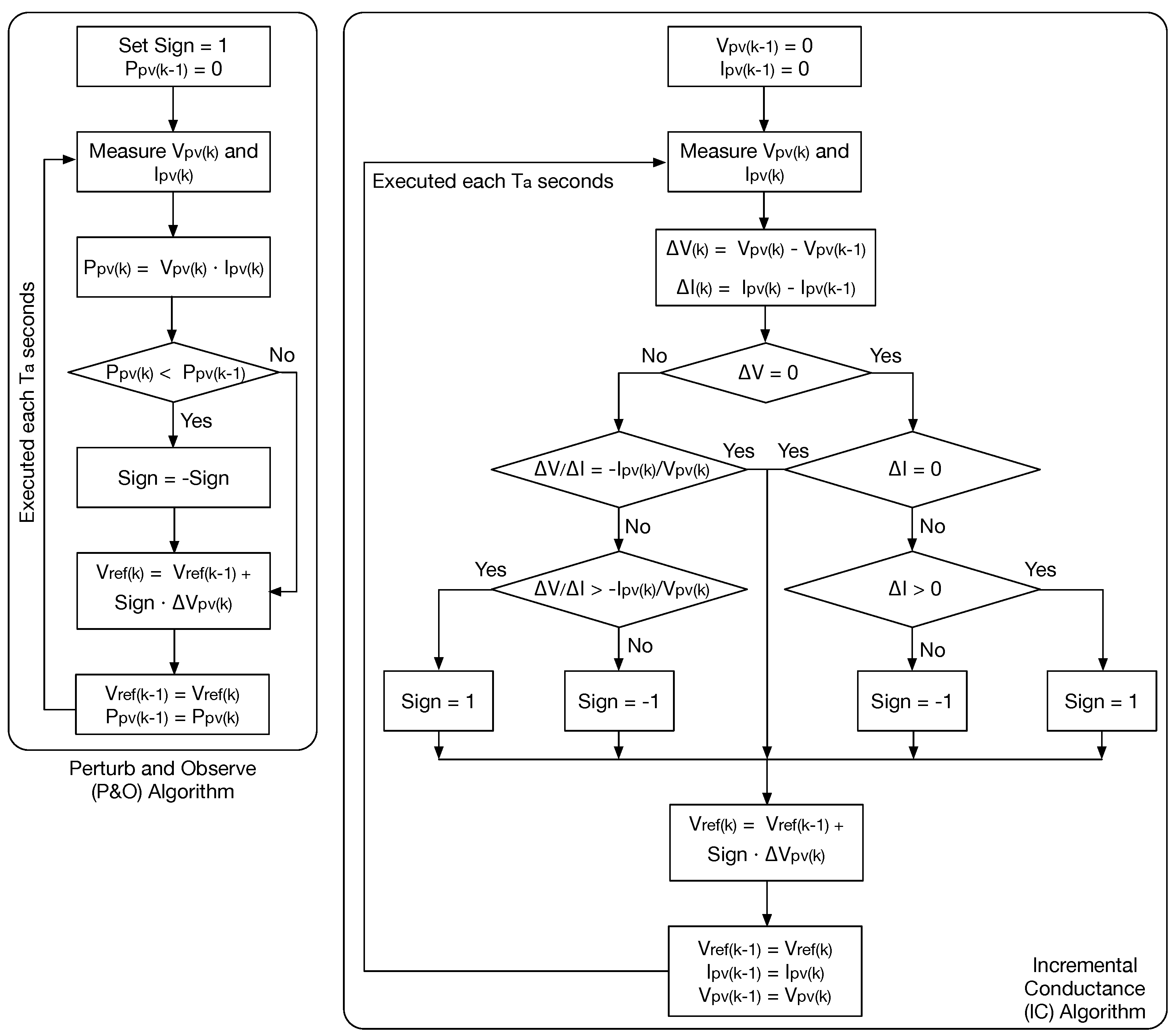
2.2. Maximum Power Point Tracking (MPPT) Algorithms

BIPV systems require algorithms to maximize the energy generated under varying irradiance and temperature conditions, adjusting the electrical load of the system for the panels to operate at their MPP.
Table 2 presents a comparative summary of different MPP tracking algorithms. The Perturb and Observe (P&O) algorithm perturbs the voltage of the array and observes the change in power; if it increases, the disturbance continues in the same direction, otherwise the direction of the disturbance is not reversed. The algorithm is straightforward to implement and has very little hardware, without the need for complex components or advanced processing. It performs well if the radiation and temperature conditions are stable and without partial shading. However, in the face of slow changes, it can quickly adjust the point of operation. In the same way, it has three significant disadvantages: stable conditions oscillate around MPP, reducing its efficiency; it can get caught in local maximums when there is partial shading; and it is not useful in environments with rapid irradiation and temperature variations.
The Incremental Conductance (IC) algorithm compares the instantaneous conductance of the array with the incremental conductance to determine the direction of voltage change. Compared with the P&O algorithm, this algorithm is more accurate in tracking the MPP, it can better handle partial shading power curves, and produces fewer oscillations around the MPP. However, it is more expensive to implement than P&O, requires more hardware and processing power, and is affected by noise in measurements.
Optimization algorithms perform a complete sweep of the power curve of the array to identify the global MPP, which is why they are effective in mixed configurations with complex shading. This allows them to function very well under dynamic and non-uniform conditions and adapt to different configurations of photovoltaic arrays. Their main disadvantages are the requirement of high computational power, the need for advanced hardware, and the high convergence time of some of their algorithms.
AI-based MPPT algorithms such as neural networks and fuzzy logic are accurate in determining MPP, even under dynamic conditions, highly efficient in managing power curves with multiple peaks, and, therefore, quite adaptable. Their main disadvantage is the performance dependency on the quantity and quality of the data used for training; moreover, they have high complexity and implementation costs.
Finally, hybrid algorithms combine the strengths of different approaches to improve accuracy and speed, but at the same time they inherit complexity and adjustment difficulties.
The choice of the MPPT algorithm depends on the PV system’s operating conditions, such as partial shading, environmental dynamics, and available resources. Simple algorithms such as P&O are suitable for basic applications, while advanced techniques such as AI, genetic algorithms, and hybrids are more effective in complex and dynamic environments. However, the latter require greater investment in hardware and software and more careful design.
Figure 2 lists the percentage values of the publications consulted in this review classified by the type of MPPT algorithm implemented in the BIPV system described. It can be seen that the simplicity and widespread use of the traditional P&O algorithm makes it the most widely implemented technique to extract the maximum power from a photovoltaic generator in BIPV systems. Optimization algorithms have also boomed in the search for MPP in photovoltaic systems, and multiple strategies have been explored that achieve excellent results in the face of changing conditions. However, with the rise of AI and the increase in computing power, algorithms based on fuzzy logic and neural networks are increasingly proposed to achieve the global MPP of the system. Finally, hybrid algorithms have always performed excellently, but the need to consider two different strategies does not encourage engineers to implement them widely.

2.3. Partial Shading Mitigation Strategies

Partial shading is a common challenge in photovoltaic systems, which occurs when a portion of a panel or array is obscured by shadows cast by nearby objects, such as trees, buildings, poles, clouds, or even accumulated dirt. This phenomenon significantly impacts the performance of photovoltaic systems, as it reduces the amount of sunlight that reaches the solar cells and thus decreases the production of electrical energy [52,53].
When a part of a panel is shaded, the shaded cells behave like loads, which can lead to hot spots and damage in the panel. In addition, partial shading affects the panel’s current voltage curve, reducing the maximum power that can be extracted. In systems with series-connected strings of panels, partial shading on a single panel can decrease the energy output of the entire string.
It is crucial to mitigate the effects of partial shading to maximize the efficiency and lifespan of PV systems. Various strategies can be implemented to achieve this, as described in Table 3.
This paper evaluates partial shading mitigation strategies based on the MPP tracking system architecture, i.e., the DMPPT (Distributed MPPT) and CMPPT (Centralized MPPT) architectures. These are the main approaches used for energy management in photovoltaic systems, seeking to maximize energy extraction, but with differences in their implementation, complexity, costs, and applications.
The objective of the DMPPT and CMPPT architectures is the same: to maximize the extraction of electrical energy from PV panels by allowing them to operate at their Maximum Power Point (MPP), which translates into adaptation to variable irradiation and temperature conditions. Both architectures, for this, can use the same MPP tracking algorithms, i.e., P&O, IC, or other options. The search for the optimal point of operation helps to mitigate losses due to mismatches between panels, partial shading, and degradation of the modules.
However, there are multiple differences between the DMPPT and CMPPT architectures, which are summarized in Table 4. A key aspect is granularity, as the DMPPT architecture allocates one converter per panel, or small group of panels, to track the MPP independently, aiming for finer control and higher adaptability to partial shading, dirt, or degradation. This increases the system’s complexity since devices with higher computing capacity are required for control purposes, which increases costs due to additional hardware and maintenance requirements. However, it also brings other trade-offs: higher energy extraction and minimization of losses, simplicity of adaptation to new requirements since each panel (or group) is independent, and fast response to dynamic conditions.
On the other hand, the CMPPT architecture operates at the whole array level, i.e., a single converter for the entire PV system, which makes it challenging to manage mismatches between panels or partial shading. However, as the design is for a single converter, it is more straightforward, with less hardware and less maintenance, which makes it cheaper and simpler. The changes in the system are not simple since increasing the capacity of the photovoltaic generator requires one to redesign the converter for the new power level. In addition, it is slower to respond to dynamic changes in operating conditions, which decreases the energy extracted.
The CMPPT architecture is shown in Figure 3a. This kind of configuration is simple; with respect to the implementation of an MPPT strategy, in this configuration only the current and voltage of the array are required, which result in low cost applications. However, if the array operates in partial shading conditions, the Global Maximum Power Point (GMPP) may not be achieved by the MPPT strategy, as explained in ref. [22]. To overcome the issues of this configuration, DMPPT configurations are adopted to improve MPPT performance. Figure 3b shows the Differential Power Processing (DPP) configuration. This topology requires the converters to be bidirectional; in this context, flyback converters are commonly used for this applications. The aim of the configuration is to control the converters to process the minimum power possible, which reduces the ohmic losses to improve efficiency, but without providing any voltage boosting factor [23]. On the other hand, Figure 3c,d show the series and parallel DMPPT configurations, respectively. Those solutions have been used at the module level and sub-module level, as presented in ref. [22]. DMPPT architectures are useful to mitigate the effects of partial shading conditions since the power of each module can be optimized independently, which avoids the issues related to multiple peaks that exhibit power-voltage characteristic when the CMPPT strategy is applied.
In terms of energy extraction, the DMPPT configurations have the best performance, as reported in refs. [22,23]. In order to provide a numerical comparison between CMPPT and DMPPT systems, a PV array formed by three strings, each one with six series-connected PV modules, is considered. Such an SP PV array is connected to a boost converter to perform the MPPT action; this converter also increases the voltage to 200 V, which is needed to power a 110 VAC single-phase inverter. This analysis considers an irradiance and shading profile extracted from ref. [34], which corresponds to a long shading patter entering the PV array for a BIPV analysis. The irradiance/shading profiles of the PV sources are reported in Table 5, where the two first strings are gradually shaded, while the third one is uniformly irradiated.
The single CMPPT converter has a 97% efficiency, while the DMPPT system is formed by 18 small boost converters with 95% efficiency, where each converter maximizes the power produced by a single PV module. Both CMPPT and DMPPT systems were simulated in MATLAB (version 2024b) using the PV model reported in ref. [68], and Figure 4 shows the simulation results. The PV modules in the CMPPT structure produce 836.31 W, while in the DMPPT structure the same PV modules produce 1015.5 W, which is a 21.43% improvement in the power production. However, the power delivered to the DC-link is affected by the power converters, where the CMPPT and DMPPT systems deliver 811.8 W and 964.6 W, respectively; hence, the DMPPT solution provides 18.82% more energy to the inverter (DC-link).
Based on the previous analyses and simulations, the DMPPT architecture is appropriate for installations where partial shading is common, for example, buildings or installations with heterogeneous panels, which must be managed individually, or systems in highly changing irradiation or temperature environments. Instead, the CMPPT architecture is helpful in large solar plants with uniform operating conditions and homogeneous panels.

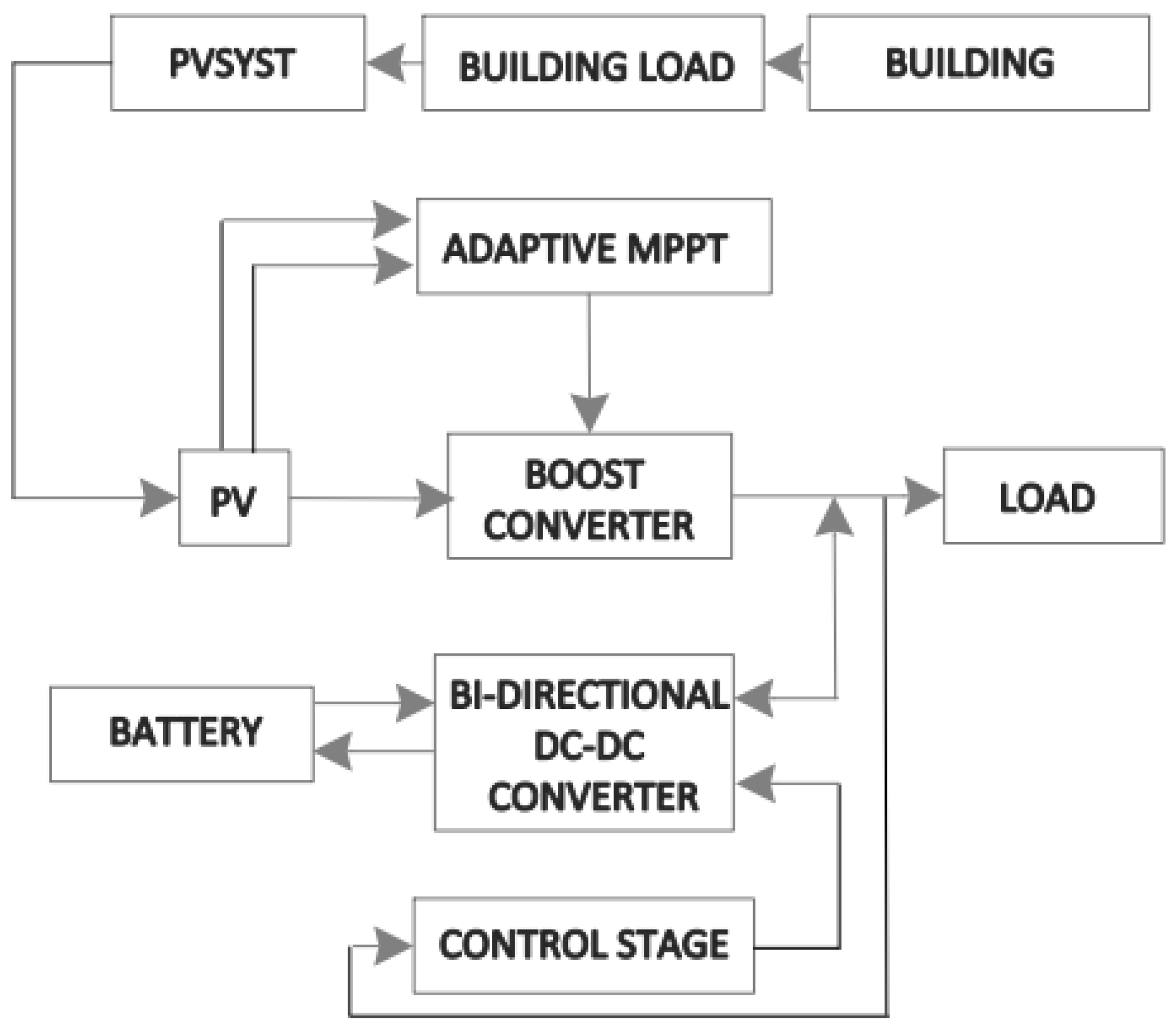
2.4. Voltage Bus Selection

The choice between a Direct Current (DC) or Alternating Current (AC) bus has essential implications for the BIPV system, as there are multiple factors to consider: energy efficiency, costs, compatibility with existing equipment, and local regulations.
In buildings with a high proportion of DC loads, such as LED luminaires, electronic devices, and battery storage systems, a DC bus can lower costs by avoiding multiple power conversions, as PV panels generate DC electricity. This avoids conversion to AC, eliminating the need for inverters, reducing losses, and reducing the number of devices, making the system more straightforward and at a lower cost. Additionally, the losses due to transmission in DC lines are lower than in AC lines since, in DC, they are only resistive, while in AC there are also capacitive and inductive losses. However, compatibility with existing installations and regulations are major obstacles to the implementation of these buses. Many pieces of industrial equipment and household appliances are designed for AC operation; moreover, regulations in most countries are geared towards AC systems. Thus, implementing the BIPV system with a DC bus necessarily requires inverters to meet AC loads and use existing infrastructures.
Some disadvantages of DC bus systems that become advantages of AC bus systems are as follows: compatibility with existing infrastructure, wide equipment availability, and regulations or standards. Their disadvantages lie in the losses associated with DC–AC conversion, the complexity and costs associated with the need for synchronization with the grid, more equipment and higher maintenance, and, finally, the lower efficiency when feeding DC loads since an additional AC–DC conversion would be required.
Not everything has been said regarding the selection of the bus for a BIPV system, since the trends in several countries are towards the increase of DC loads and the adoption of standards for this type of system, considering hybrid solutions that combine DC and AC buses: the first for luminaires, electronic devices and storage, the second for traditional loads.
Choosing between an AC or DC voltage bus in BIPV systems depends on the specific building characteristics, predominant loads, costs, and local regulations (see Table 6). While an AC bus is more compatible with existing infrastructure and current regulations, a DC bus offers higher energy efficiency, and it is more suitable for buildings with a high proportion of DC loads. Hybrid solutions and future trends towards DC electrification suggest that BIPV systems could evolve towards a higher adoption of DC buses, especially in modern, sustainable buildings.
BIPV systems with DC buses represent a promising solution for modern buildings, offering efficiency, flexibility, and compatibility with emerging technologies. In this article, only works with DC buses were analyzed.
However, hybrid AC–DC bus-based solutions require bidirectional inverters with advanced SPWM (Sinusoidal Pulse Width Modulation) features. These control strategies allow DC voltage regulation for various loads, independent active/reactive power control, high efficiency, and unity power factor operation [74,75,76]. In addition to enabling bidirectional power flow, these devices must have high performance with intermittent generation typical in BIPV systems. The architecture is generally centralized, allowing easy and efficient connection of renewable energy sources and the utility power grid [77]. There are multiple proposals in the literature for bidirectional inverters that can be useful as an interface between AC/DC buses, some of which have initially been used for plug-in electric vehicles. The trend is to minimize losses by eliminating stages, decreasing switches, implementing soft switching techniques, and defining multiple ports for different loads, AC–DC, and high or low voltage [78,79,80].
On the other hand, integrating bi-directional converters in BIPV systems to interface AC buses with DC buses is a great opportunity to incorporate the growing V2G technologies with electrical installations in buildings. However, its implementation requires addressing several key technical challenges [81,82]:
  • Standardization of DC buses: The lack of unified regulations for Direct Current (DC) distribution systems limits interoperability between BIPV, V2G, and smart grids. Future studies should propose regulatory and technical frameworks that facilitate safe and efficient integration.
  • Bidirectional inverter design: Electric vehicles require power converters with high dynamic responsiveness, low harmonic distortion, and bidirectional capability. Research into advanced inverter topologies, such as multilevel or Wide Band Gap (WBG) semiconductor-based structures, could improve performance and reliability.
  • Conversion and distribution efficiency: To maximize the economic viability of BIPV-V2G systems, ultra-high efficiency conversion devices and optimized distribution architectures that minimize losses are required, especially in environments with intermittent generation.
  • Availability in adverse conditions: It is crucial to develop energy management strategies that ensure the availability of charging stations, even during periods of low PV generation or reduced demand. Solutions such as hybrid storage (batteries + supercapacitors) or AI-based load prioritization schemes could be explored.

2.5. Electrical Models of Photovoltaic Panels

Not all panels are equally suitable for building integration. Different panel technologies have unique characteristics that are reflected in their electrical models. Table 7 summarizes the electrical models of photovoltaic panels classified by technology.
In general, electrical models are based on the behavior of a PN junction diode. Crystalline silicon technologies (monocrystalline and polycrystalline) are the most common and use one or two diode models, represented by transcendental equations relating the panel current to the photogenerated current, the reverse saturation current and the current representing the recombination losses at the PN junction. The two-diode model has a more faithful representation of the PV panel under low irradiance and high-temperature conditions, so it should be preferred in BIPV installations using crystalline silicon panel technology.
Because of their flexibility and low cost, amorphous Silicon (a-Si) and Copper-Indium-Gallium-Selenium (CIGS) thin-film (Thin-Film) panels are the most appropriate for installation in BIPV systems, as they can be easily fitted to facades, roofs, and windows. These panels use the model of one diode, but compared to crystalline silicon panels the model parameters must be adjusted to capture their unique properties.
In summary, the design of BIPV systems should prioritize solutions that maximize energy efficiency, architectural adaptability, and cost-effectiveness. To this end, a mixed configuration of the panel array, combining series and parallel connections, is recommended, as this improves partial shading tolerance and reduces power losses compared to purely series arrays. Regarding MPP tracking, it is crucial to employ advanced algorithms (such as enhanced P&O or artificial intelligence-based) that efficiently manage dynamic shading and gradual degradation of the panels. This ensures optimal performance over time, even in urban environments with varying obstructions. The DMPPT architecture is preferable to centralized systems, as it allows individualized control per panel or small groups, improving overall system efficiency under heterogeneous irradiance conditions. The joint implementation of DC and AC buses is advantageous since the DC bus reduces conversion losses in direct current loads (LED lighting, electronics), while the AC bus facilitates integration with the power grid and conventional equipment. Finally, the panel modeling must be adapted to the adopted technology (monocrystalline silicon, polycrystalline, thin-film, or transparent cells), considering its location (facades, roofs, or windows). For example, semi-transparent panels in windows require models that consider their light transmissivity, while modules in facades should be evaluated for their mechanical and thermal resistance.
In conclusion, a well-designed BIPV system must integrate these aspects to guarantee high efficiency, durability, and versatility, ensuring its technical and economic viability in NZEB-focused environments.

3. Maximum Power Point Tracking Methods in BIPV Applications

This section is devoted to describe the highlights of reported works found relevant to the Maximum Power Point Tracking (MPPT) strategies used in BIPV applications. The analysis of the selected papers was focused on features such as the MPPT algorithm, converter, PV model, PV structure (array, panel), type of integration in the building, and partial shading condition analysis. At the end of the section, a summary of the works discussed is presented along with some key findings to provide selection guidance in MPPT solutions for BIPV systems.
In ref. [46], an adaptive predictive control scheme based on an Adaptive Neuro-Fuzzy Inference System (ANFIS) is proposed for an Incremental Conductance (IC) MPPT strategy. Two solar panels, each 160 W, are used to evaluate the approach. The module orientation analysis was performed using PVsyst software (version 7). The solar PV panels are at a fixed tilt, i.e., facing south with a tilt angle of 130° and 0° azimuths (this description indicates the panels are installed on a wall). Figure 5 shows a block diagram of the proposed solution.
In this work, the authors assumed a switching frequency of 50 kHz, and the inductors and capacitors were ideal. As mentioned, the authors proposed an IC MPPT strategy. The error between the conductance and negative of IC is an input to the fuzzy logic controller. The fuzzy rule base with current and voltage input membership functions include L: low, M: medium, H: high, ML: medium-low, and MH: medium-high. The system included a battery charge stage formed by a bidirectional converter. Figure 6 shows the schematic of the battery charge controller.
As the figure shows, there are two PI controllers. One in an outer loop, which regulates the voltage output, while the one in the inner loop computes the duty cycle for the bidirectional converter based on the current error. The transfer function of the outer and inner loops of the bidirectional converter are given by (1) and (2).
G v i = 1 D 1 S L R 1 D S C + 2 R
G i d S = V o u t S C + 2 R S 2 L C + S L R + 1 D 2
The ANFIS strategy is based on the Takagi–Sugeno method. The authors used data obtained from radiation measurements and simulations. The work considered 209 data points to build the model during the training process and found 42 data points to validate the model. The system was implemented in Simulink/MATLAB (Version 2020a). The fuzzy logic controller and the ANFIS controller were compared. The fuzzy logic controller provides a duty cycle of approximately 0.687, whereas the ANFIS provides 0.684 with fluctuations. It is not discussed if those fluctuations cause any malfunction in the system. The authors concluded that the fuzzy logic controller provides more power at the output. However, it is not clear how the IC MPPT operates. According to the authors, it is observed that the FLC gives better efficiency than the ANFIS model (90% to 95%), but the ANFIS model is advantageous as it makes the hardware implementation simpler and reduces the complexity of the system by its autoupdate technique, which makes it more reliable for real-time applications. The aforementioned results were obtained through simulations. The authors performed experimental validation using a 320 W PV array, but there is no analysis concerning the results in the power obtained by using the proposed MPPT strategy. There are no details or discussions concerning if the model used for the PV panels was the one available in Simulink/MATLAB (version 2020a) or if another structure, such as a one or two diode model, was used. In the same way, the authors did not provide information on the effect of the controllers on BIPV applications.
In the work presented in ref. [22], the authors compared the application of a Perturb and Observe (P&O) MPPT algorithm at different levels for a BIPV system. In this way, the first level is the centralized MPPT, then MPPT at the module level, and finally MPPT at the sub-module level. The analyzed array was formed by six modules connected in series; each module with three sub modules. The irradiation profile under study considered partial shading. The analysis was carried out in Simulink/MATLAB. In the centralized MPPT application, the obtained power was different from the theoretical power by approximately 32.5%. In the module level MPPT application, the same irradiation profile was evaluated, achieving an improved performance in comparison with the centralized MPPT, which corresponds with an increase of 9%. This put into evidence the different behavior of the MPPT between the centralized version and the module version. In the third case, the MPPT application was evaluated in a similar way as the two latter cases, with the same irradiation profile. In summary, for the first simulation (central MPPT) 326.64 W and 65.55% tracking efficiency was achieved; the global MPP could not be tracked due to the multiple maximum locals in the P–V (Power vs. Voltage) curve. In the second simulation (module level MPPT), a value of 404.36 W for the power was obtained. At the sub-module level, the power is around 640 W, which corresponds to 96% more power than the central MPPT and 58% more power than the module-level MPPT. For the second simulation scenario, with the MPPT at the sub-module level, 30% more power can be obtained than the central MPPT and 18% more than the module level MPPT. From the results, it is evident that the sub-module level MPPT solution is more suitable for BIPV type systems. This study provides valuable information in terms of the behavior of the MPPT at different levels; it is clear that partial shading is an issue for BIPV systems. However, there is not a detailed discussion concerning the BIPV system characteristics as well as the PV model used for the analysis.
The authors in ref. [32] presented a comprehensive performance analysis among three different MPPT techniques—Perturb and Observe (P&O), Incremental Conductance (IC), and Fuzzy-Logic Control (FLC)—for BIPV systems in varying solar irradiation conditions but not partial shading. The double diode model is used for representing the BIPV module. The authors considered 270 W high performance crystalline glass to glass BIPV modules manufactured by Topsun Energy Limited. The BIPV modules can be applied to the facades, canopies, skylights, and windows of buildings. Figure 7 shows the proposed structure in this paper.
A non-isolated DC–DC boost converter was used in this work for MPPT algorithm applications. Equations (3) and (4) correspond to the design of the inductor and capacitor of the converter, where I r is the ripple current in the inductor, f is the switching frequency, and Δ V o u t is the output voltage ripple.
L = V i n × V o u t V i n I r × f × V o u t
C = I o u t × D f × Δ V o u t
The P&O and IC MPPT strategies proposed by the authors correspond to the widely used ones; changes were not proposed. The FLC MPPT proposed in this work is an architecture of basic type-1, which has as the main components knowledge-based rules and an inference engine, a fuzzification unit, and a defuzzification unit. The entire process is executed through the accumulation of all the procedures of fuzzification, rules evaluation, rule output accumulation, and finally defuzzification. In the fuzzification process, the input data are processed by converting the sharp values of the input parameters to a function of fuzzy membership. The authors proposed five linguistic variables, which are NL (negative-low), NH (negative-high), PL (positive-low), PH (positive-high), and ZE (zero); the input and output parameter limits are assigned. The membership functions have the widely known trapezoidal and triangular shapes; the method of center of area was used as the defuzzification method. The architecture of the FLC is presented in Figure 8. In this way, the input to the FLC is the error in the power at m, defined as E r r ( m ) time and a differential error, defined as Δ E r r , which corresponds to the difference between E r r ( m ) and E r r ( m 1 ) . The output corresponds to a modification in the duty cycle, defined as Δ D .
The analysis of the controllers was performed in MATLAB (version 2020a) with the fuzzy logic toolbox, but there was no information concerning if Simulink or another tool was employed for representing the PV panels and the converter. The BIPV system consisted of a 7 × 16 SP array with a maximum power output of 30.242 kW at 1000 W/m2, 24.314 kW at 800 W/m2, and 18.291 kW at 600 W/m2. The time period with the irradiation condition applied to the BIPV array for simulation are 0–0.5 s for 1000 W/m2, 0.5–1.0 s for 800 W/m2, 1.0–1.5 s for 600 W/m2, and 1.5–2.0 s for 1000 W/m2. The components of the non-isolated boost converter used in simulations are as follows: capacitance at BIPV array side is 25 μ F, boost converter inductance L is 5 mH, boost converter capacitance C is 1200 μ F, switching frequency f is 5 kHz, and load resistance R is 5.3 Ω . Table 8 summarize the simulation results.
The results showed that the FLC MPPT strategy is faster than the P&O and IC methods. For the simulation where the irradiance was 600 W/m2, the FLC MPPT took 0.02 s, which means 37.7% and 29.8% less time in comparison with P&O and IC, respectively. For the simulation where the irradiance was 800 W/m2, the FLC MPPT took 0.018 s, which means 37.5% and 33.3% less time in comparison with P&O and IC, respectively. Finally, for the simulation where the irradiance was 1000 W/m2, the FLC MPPT took 0.02 s, which means 46.5% and 40.8% less time in comparison with P&O and IC, respectively. The results put into evidence the similar behavior of the algorithms with respect to the power extracted from the array and the efficiency. However, the FLC had the best performance. In addition, the FLC method provided an improvement in the execution time. This work can be considered a good resource of information, but there is not a detailed discussion concerning BIPV characteristics and their influence in the performance of the controllers and MPPT strategies.
In ref. [42], the authors proposed an MPPT algorithm called the Three-Stage Variable Step Size (3SVSS) method. The method is described as follows: In stage 1, the output voltage of the module is controlled to 75% of the open-circuit voltage without detecting the voltage and current of the module. The following two stages, when approaching the maximum power point, are a determination of the disturbing direction and step size by comparing with smaller set values Δ V 1 and Δ V 2 ; hence, the step sizes are smaller than one of the traditional two-stage variable step-size control strategies. In the analysis, the authors considered thin-film PV modules modeled through the one-diode model. A flowchart of the method is shown in Figure 9.
On the other hand, based on the traditional Double Closed-Loop (DCL) controllers in CCM and DCM, the work introduced a CCM/DCM hybrid control strategy where correction factors were defined. Based on the fact that, when the irradiance decreases dramatically or the load increases abruptly, the boost converter operates in DCM, and different state-space average models and transfer functions define controller behavior, the authors proposed the following: when the converter is working in CCM, the correction factor is 1, and it has no effect on the system; when the converter is working in DCM, the correction factor can compensate for the output of the CCM feedback. The validation of the proposed methodology was made through simulations in MATLAB and experimental tests. Both validation platforms considered two cases: fixed irradiance of 1000 W/m2 and drastic changes decreasing 200 W/m2 every 0.5 s until 2 s. Then, increasing 200 W/m2 every 0.5 s until 3.5 s. Partial shading conditions were not considered. In simulations, the parameters of First Solar FS-4112 thin-film modules were used; however, the authors did not give information concerning the amount of modules used, though they mention a series connection. PV modules were modeled by using the one-diode model. Comparative simulation was carried out to compare the performance of the proposed method with traditional methods: P&O, Two-Stage Variable Step Size (2SVSS) method, and DCL control method. The simulation results show that the proposed control strategy caused less power loss than the other three methods and it works at a higher efficiency under low irradiance. The CCM/DCM hybrid control method could deliver more power from thin-film modules under such conditions. The experimental setup considered a PV1000 pv simulator to emulate real modules using the same parameters of the modules in the simulation. The same two cases for the irradiance were used in the experimental validation. The control algorithm was implemented in the TMS320F28335. The results were consistent with the simulation results, which validates the proposed methodology. However, there is not a detailed analysis of the differences in the performance of the MPPT strategy and the controller with respect to the simulation performance. In the same way, the authors concluded that the proposed method works at a higher efficiency under low irradiance, but the work did not present an analysis of the losses to calculate the efficiency. In the context of the BIPV systems, the authors did not investigate how the presented analysis pointed to the particular behavior or operational characteristics of BIPV systems. However, from the simulation results the authors affirmed that the proposed method was the only method that could deliver the theoretical maximum power, which is considered particularly important for BIPV applications, since the mounting angles of thin-film BIPV modules are likely perpendicular, with large deviation from the optimal elevation angle.
The authors in ref. [29] proposed the design of an MPPT strategy with a DC–DC boost converter for a PV array formed by Perovskite Solar Cells (PSCs). The authors proposed using the P&O algorithm along with a Sample and Hold (S&H) stage with a fast acquisition time, which reduces sample time and power annulment period. The low droop rate of the S&H helps to prevent the PV operating point from straying from the MPP during the sampling period. Two cases studies were considered, one under natural light and another under artificial illumination using an SP array of 4 × 2 PSC. The experimental results validated the effectiveness of the strategy proposed by the authors for both natural light and artificial illumination conditions. However, a detailed analysis of the results was not presented, nor was information concerning the irradiance pattern. In the same way, the authors did not give details on the benefits of the proposed solution and the BIPV concept considering the use of PSC. On the other hand, in ref. [86], the authors presented a study case of a bus stop shelter form by a structure with PSC to evaluate its potential performance and the use of this type of cell technology in BIPV applications. The system includes a P&O-based MPPT strategy and a charge controllers to supply the load. The MPPT proposed strategy is made through a boost converter. Validation was performed by using simulations executed in Simulink/MATLAB. The structure under study considers the integration of perovskite PV modules on the roof and all the sides of the bus stop shelter. The MPPT control was applied in each array for each side and the roof of the structure, which can be considered as an MPPT-distributed architecture. The load of the PV system is mainly electronic, including lighting and a battery pack, which feed the load in the night. The analysis did not consider partial shading or drastic changes in the irradiance. The simulation results showed that the MPPT control is effective, but there is no deep analysis of its performance, efficiency, or other aspect. The authors did not present comments concerning the aspects related to BIPV for replying or escalating the solution to other structures. Neither of the works [29,86] provide significant information concerning the modeling of PSCs oriented to BIPV applications.
The work presented in ref. [33] studied the design of a Buck-Boost Single Stage Microinverter (BBSM) for BIPV applications. The authors proposed a topology based on four semiconductor switch controlled devices, two uncontrolled devices (diodes), two inductors, and a C-type filter. The authors presented an exhaustive analysis of the modes of operation of the buck-boost converter to obtain the mathematical model. From the model they proposed a set of design equations for the inductors and the C filter. In this work, a P&O MPPT technique was implemented. The validation of the work was performed in Simulink/MATLAB; the PV module used was a thin-film module, which has been used for BIPV applications; its parameters were adopted from a commercial datasheet. The model of the PV module is the model provided by Simulink. The validation considered changes in irradiance, but partial shading conditions were not included in the analysis. Experimental validation was also performed by using a PV simulator and an electronic load. Both simulations and experimental tests confirmed the good performance of the BBSM in terms of efficiency reaching values of 96.4% in the experimental validation, and current total harmonic distortion, which was around 5%. In addition, from the results, the leakage current was considered negligible. In general, the authors focused the analysis on the performance of the buck-boost single stage microinverter; the authors gave the following conclusions on the BBSM application in BIPV systems: (i) light in weight, which is a desirable characteristic in BIPV systems; (ii) the topology is more efficient and has less passive elements than other topologies; and (iii) the topology reduces leakage current, which reduces EMI and harmonic distortion influence.
The approach presented in ref. [43] proposed a novel MPPT scheme for curved/bent thin-film flexible PV modules, which is a combination of direct and indirect methods. This MPPT scheme relies on the threshold solar angle (determined from the analysis of the experimental data) for the given conditions and concludes on the existence of single or multiple power peak regimes. Based on this information, the MPPT control is transferred to the conventional MPPT scheme (P&O method is used in this work) or the Scanning Window Technique (SWT). The SWT is composed of two stages:
  • In the first stage, the proposed model considers the dependence on solar irradiation, module temperature, and curve angle and provides the position and width of a scanning window in which the global maximum can be found.
  • In the second stage, the global maximum is tracked within the scanning window by using the P&O method.
The authors proposed a method for modeling thin-film curved PV modules based on experimental data obtained at different hours of the day and at different angle positions of the module. The information put into evidence that the dependence of flexible PV module parameters on irradiance, temperature, and angle is nonlinear and highly complex. Therefore, the data fitting for the proposed models of various flexible module parameters is carried out by using nonlinear regression analysis with the Levenberg–Marquardt (L–M) method, which represents the true behavior of curved panels for a range of conditions. The set of equations provided by the analysis for modeling the flexible PV module is given in Equations (5)–(14).
V o c T = V o c T 1 γ × Δ T
Δ T = T T 1
In (5), γ = d V o c / d T and T is the localized module temperature, while T 1 is the reference temperature.
I s c G , θ c = A θ C × G + B θ C + C × l n T
G is the localized solar irradiation, I s c (predicted) is the PV module current under no-load conditions, A θ C is a coefficient that depends on θ C , and B θ C shows the dependence of I s c on θ C . C is the coefficient of temperature dependence of I s c , which is independent of curve angle. In the following equations, A θ C and B θ C are defined. α 1 , α 2 , β 1 , and β 2 are the regression coefficients.
A θ C = α 1 × θ C + β 1
B θ C = α 2 × θ C + β 2
The authors also proposed to express the dependence of the Fill Factor (FF) on the irradiation as well as the curve angle from regression analysis, where f 1 , f 2 , f 3 , f 4 , and f 5 are the regression coefficients.
F F G , θ C = f 1 f 2 × θ C f 3 × G + f 4 × θ C 2 + f 5 × θ C × G
Based on an analysis performed on the FF behavior, the multiplication factors V f a c t o r and I f a c t o r are defined. These factors depend on the irradiation, temperature, and curve angle, as per the following relations:
V f a c t o r = F F G , θ C k
I f a c t o r = F F G , θ C ( 1 k )
Considering the previous equations, the authors proposed two more expressions for calculating the MPP voltage and current:
V M P = V o c T × V f a c t o r
I M P = I s c G , θ C × I f a c t o r
The concept of scanning window was derived from the fact that the MPP occurs at different percentages of open-circuit voltages for a specific module technology. In this way, the V f a c t o r is one of the key parameters to determine the scanning window for power optimization from the flexible PV module. The MPPT scheme proposed in this method uses solar irradiation, Estimation Solar Angle (ESA), and the curve angle (which must be known before the installation) as input parameters. After evaluating the threshold conditions, the algorithm decides whether to adopt a scanning window strategy or a conventional MPPT strategy. A lookup table provides threshold solar angle values for various curve angles. Then, the scanning window technique is applied as follows:
  • The mean value of the scanning window width, and hence its position, is calculated for the given conditions of irradiation and curve angles.
  • The information obtained in the previous step serves as the starting point for the scanning of the power–voltage curve and takes the operating point close to the global MPP (with no other peaks expected). The MPPT control is now transferred to the P&O scheme.
The algorithm was validated through experiments for various irradiation and curve angle conditions. The first scenario was for a 22 °C curve angle at 380 W/m2 and 40 °C temperature. The results showed the proposed method achieves the MPP, while a common P&O method did not reach the maximum. A second scenario in which the irradiance was 500 W/m2 was tested; in the same way, the proposed method achieved better performance in comparison with a common P&O algorithm. For all cases, the tracking efficiency of the proposed technique is 99.7%; however, there is no detailed procedure for the efficiency analysis. The authors did not provide information concerning the dataset of the PV module. The comparison with the common P&O was made for the power achieved; there is no analysis concerning other aspects of the algorithm’s performance. Finally, there is no discussion on the impact of the proposed solution in BIPV applications. Nevertheless, this work could be considered as the base for the analysis of other surfaces that can be found in BIPV applications.
The work presented in ref. [50] proposed a maximum power point tracking technique that can detect failures by detecting the combined impedances of the solar cell array using switching ripples that are measured using just one voltage and current sensor. The authors considered as a study structure 10 PV modules connected in parallel and attached to the windows of a building. Solar modules were installed on the west-, south-, and east-facing sides of the building, which means the ten PV modules surround one floor of the building and are connected to a DC–DC converter to perform the MPPT control.
The proposed control method estimates the maximum power point by calculating the electromotive force E and the combined internal impedance R i n of the solar cell from the solar cell voltage V p v and the current I p v , including switching ripple. The authors proposed the following equations:
R i n = V p v A C I p v A C
E = R i n × I p v + V p v
The methodology for the MPPT strategy is based on the fact that the maximum power point of the solar cell is achieved when the combined internal impedance R i n of the equivalent circuit and the voltage of the main circuit are equal. Therefore, the measured value of the solar cell voltage V p v is half the electromotive force E. The duty cycle is then adjusted to maintain stable operations at the maximum power point; the authors provided information concerning the change in the duty cycle if the application uses a boost or a buck converter. The flowchart of the proposed approach is presented in Figure 10.
The proposed solution was implemented in MATLAB (version 2020a). The operation conditions consider 1000 W/m2 and the use of a boost converter. The work did not include partial shading conditions. The simulation results show that the proposed MPPT technique responds to the changes provoked by the simulated failure in one of the PV panels, which changes the operating conditions in the array. Experimental tests were also performed in which the proposed solution also showed the expected results. There is no discussion on the efficiency of the proposed MPPT strategy, nor an analysis concerning the aspects related to BIPV systems in which this solution could be applied.
From the works reviewed and discussed in this section (see Table 9), the following comments are extracted:
  • The most used MPPT strategy is the P&O, which is a trend also evident in conventional PV systems. However, strategies based on FLC are also a good option for BIPV applications, as shown in refs. [32,46].
  • The works presented in refs. [29,32,86] integrate PV modules in facades and proposed the use of P&O algorithms, achieving good performances according to the authors. However, validations are not clear concerning the behavior of the MPPT algorithm under partial shading conditions, which could be a very common issue for facades. It would be useful to go deeper into the study of the potential PV generation in facades by using the information of those works as background.
  • On the other hand, the works in refs. [22,31] considered partial shading conditions in their analysis and proposed P&O techniques to mitigate the effect of shadowing.
  • Another aspect identified in this section was the use of the boost converter in all reviewed papers, which is also very common for conventional PV systems.
  • Concerning the PV module or cell modeling, there was no detailed information. However, most of reviewed works used the one-diode model. Two of the works discussed in this section use the double-diode model, which is suitable for low irradiance levels. Such a condition is very likely in BIPV systems that include facades or other structure elements installed perpendicularly to the ground. In this way, it would be useful to perform a comparison of the analysis proposed in refs. [31,32] using the one-diode model or other models to evaluate the effect of the low irradiation levels and the performance of the MPPT strategies proposed in those works.
  • The work reported in ref. [43] presents an interesting approach for modeling curved PV modules used in roofs. The proposed method can be useful to analyze similar structures that could be present in buildings. In the same was, the proposed methodology can be used for modeling other types of PV module technologies, such as bifacial panels and PV windows.
  • The approaches presented in refs. [29,86] proposed the use of perovskite solar cells as a suitable options for PV elements to apply to facades. However, the authors did not discuss details concerning the model of the PV cell, which could be very helpful in order to analyze the impact in the design of the MPPT strategy but also in the study of the partial shading condition impact on PV generation.

4. Granularity Level of the MPPT Action

Concerning the particular application in BIPV systems, several solutions have been focused on both CMPPT and DMPPT approaches. However, it is difficult to find clear guidelines for selecting power converters and connection architectures for BIPV systems. Therefore, Section 4.1 and Section 4.2 discuss the most recent papers dealing with CMPPT and DMPPT solutions in BIPV applications, respectively, identifying the advantages and disadvantages. Then, Section 4.3 synthesizes the connection types, power converters, control systems, and MPPT algorithms found in those CMPPT and DMPPT solutions, providing critical analyses of the solutions. Finally, Section 4.4 discusses the cross-coupling problem generated by DMPPT series connections, using equations and simulations to evaluate the classical solutions reported in the literature, and also proposes a mitigation strategy.

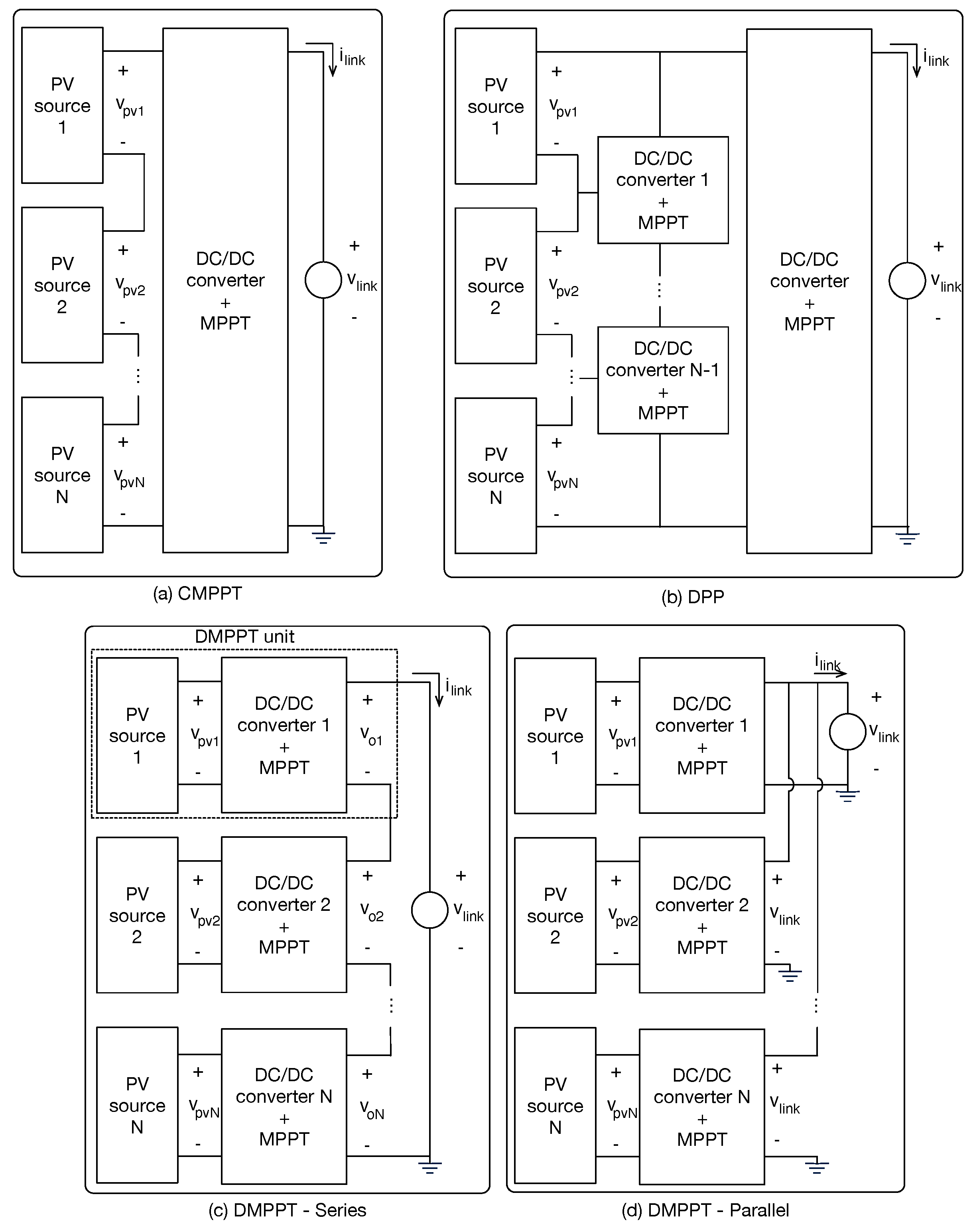
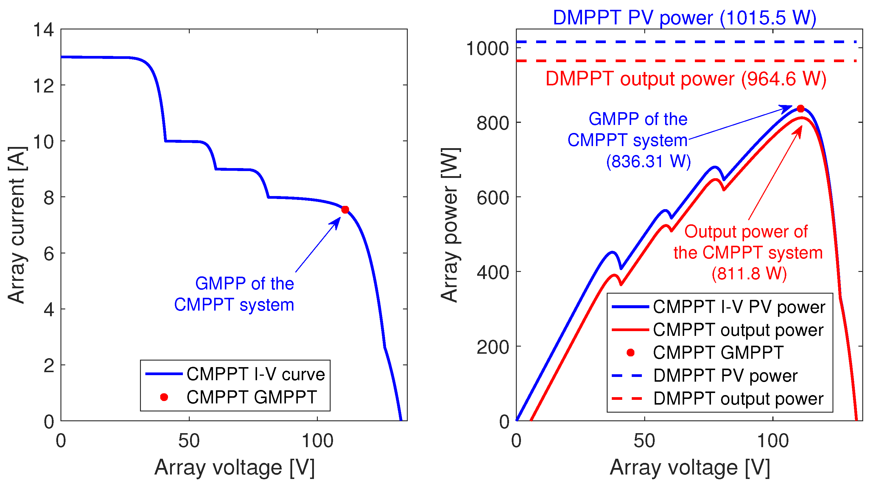
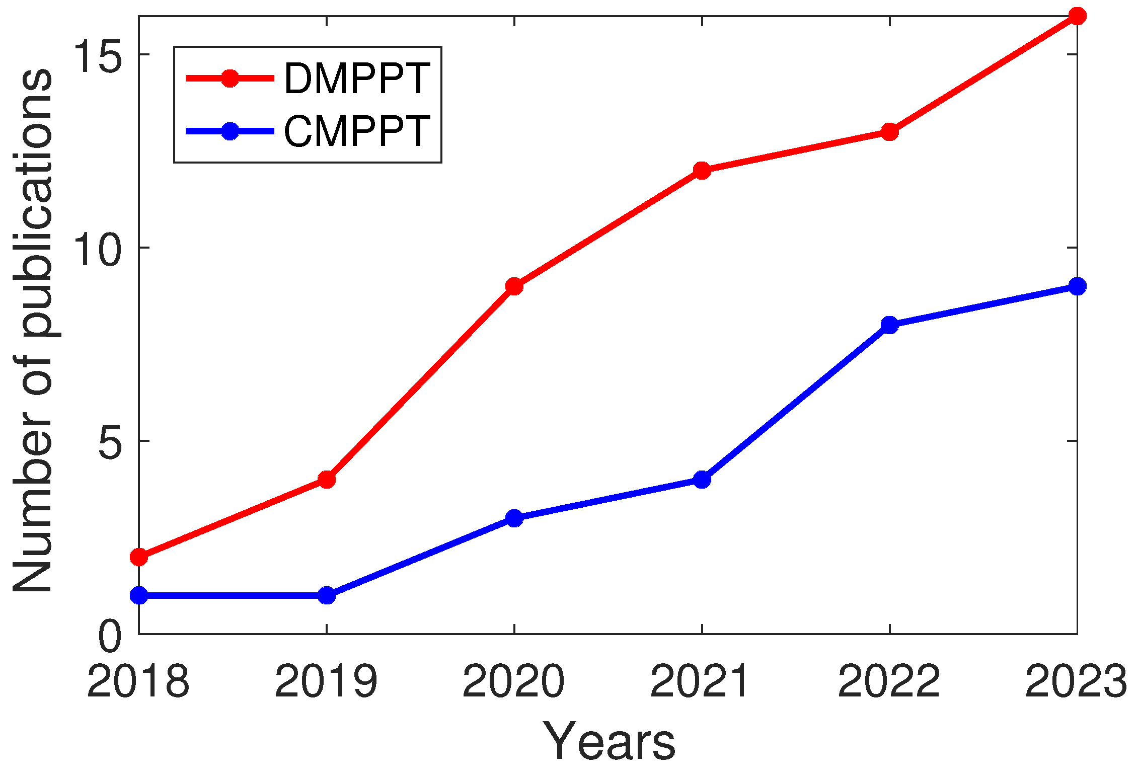
4.1. CMPPT Solutions for BIPV Systems

The work reported in ref. [64] proposes a centralized solution based on a boost converter, which is regulated using a Perturb and Observe (P&O) algorithm to optimize the power production. This is a common approach since both the boost converter and the P&O algorithm are well known and require a simple implementation. However, the lack of a high-frequency controller makes the PV system susceptible to errors in the MPPT action due to perturbations generated in the DC-link. In fact, this solution considers a grid-connected system; hence, the DC-link capacitance must be large to avoid the 120 Hz voltage oscillation, thus producing reliability problems.
A similar structure is reported in ref. [65], which analyzes different power converters to form the first-stage of single-phase PV inverters. The first solutions reported in this review are focused on CMPPT systems, where the boost converter is the first one suggested to perform the MPPT action, but the authors point out the disadvantages of this topology: the low voltage-conversion ratio achievable in real applications due to power losses, and the lack of isolation. Therefore, the Dual Active Bridge (DAB) topology is proposed as the MPPT stage for CMPPT inverters, which uses a high-frequency transformer to increase the voltage-conversion ratio and introduce galvanic isolation. The main disadvantages of the DAB converter are the large number of elements required, the complexity in the MOSFET drivers, and the complexity in the control design. In fact, to achieve a high efficiency, it is required to drive both bridges at 50% duty cycles, while the phase-shift between both bridges define the power flow, which is not a trivial task. Along this line, this paper is mainly focused on the control strategies for the grid-connection, while the high-frequency controller for the first stage is not discussed.
The mitigation of partial shading effects in BIPV systems is discussed in ref. [87], which uses a boost converter to perform the MPPT action of a centralized system. This work is focused on a Reserve Generation Algorithm (RGA), which is used to reduce the impact of partial shading conditions on the AC grid. The boost converter is selected due to the simplicity of the topology, and a PI voltage controller is designed, using the root-locus method, to reject DC-link perturbations, thus ensuring the correct tracking of the MPPT reference. Most attention is devoted to RGA, which deloads the PV array to provide a frequency support function, thus requiring one to operate the PV array below the MPP power without scanning the whole PV curve. In addition, a strategy to detect the partial-shading condition is proposed, which can also be used to trigger diagnostic algorithms. Finally, the main drawback of this solution concerns the linearity of the high-frequency control system, which does not ensure the same performance under all the operation conditions.
Complex power stages for BIPV systems have clearly recognizable stages based on classical converters. In this way, the high-gain non-isolated three-port converter reported in ref. [37] uses a boost converter to interface the PV array and apply the Incremental Conductance (IC) MPPT algorithm. A second converter, which behaves as a boost converter with a voltage multiplier, regulates the DC-link voltage, and an inverter delivers the PV power to the grid or AC load. The MPPT converter does not have a high-frequency controller; hence, the MPPT action can be affected by perturbations from the second converter. However, the second (DC-link) converter is controlled using a PI structure to avoid DC-link damages, but such a liner controller is unable to provide a consistent performance under all operation conditions. In conclusion, the high-gain is achieved by connecting in cascade several converters, which could be difficult to control depending on the power levels of the PV system and can also affect the overall efficiency.
The integration of lithium-ion battery storage systems in BIPV applications is analyzed in ref. [88]. This solution uses a DC microgrid with a 400 V DC-link to transfer energy between the BIPV source, the batteries, and the AC grid. The authors selected a boost converter to interface the PV array due to its simplicity, including a high-frequency PI controller to mitigate the effect of DC-link perturbations in the MPPT action. However, as in the previous cases, such a linear controller provides different performances depending on the operation point and power level. Finally, the MPPT algorithm is not discussed, but from the simulations it could be concluded that a traditional P&O algorithm was adopted. A similar work was published one year later in ref. [89], adopting the same boost converter and PI controller to regulate the PV source. As in the previous case, the design procedure of the PI controller is not discussed; instead, more attention is devoted to the DC-link and inverter control. An improvement provided in this new paper concerns the effect of parasitic elements on the DC-link stability, which is needed to ensure the correct operation of the BIPV installation.
Another complex converter, designed as a cascade structure for high voltage elevation, is reported in ref. [90]. It was designed to interface a PV source with a 400 V DC-link in a DC microgrid, which considers both DC loads and a grid-connected inverter. The stage applying the MPPT action is a boost converter, but no information is provided about the MPPT algorithm or high-frequency controller. The main focus of the paper is the second DC stage, which is based on voltage multipliers and switched sections aimed to increase the voltage and regulate the DC-link. This DC-link regulation could have problems if the PV power production is higher than the load consumption; therefore, one of two options must be implemented: the MPPT algorithm must include a deload function similar to ref. [87] to avoid an excessive power injection into the DC-link, or the inverter and DC load have a priority disconnection function when the PV power production is low. Finally, this microgrid shows the advantages of the boost converter simplicity in terms of implementation and MPPT control.
A different approach was adopted in ref. [91] to design a high-frequency grid-connected microinverter for BIPV applications. This solution focused on replacing the classical boost topology, used as the MPPT driver, by a flyback-based solution, which provides galvanic isolation and higher voltage-conversion ratio due to the high-frequency transformer present in the flyback topology. However, no analysis of the MPPT algorithm or high-frequency controller is given; instead, the paper analyzes practical considerations for the converter design. This solution is an interesting approach since the flyback converter allows one to feed DC-links with voltages lower, equal, or higher than the PV voltage, thus providing higher flexibility to traditional CMPPT systems based on boost converters. Finally, the galvanic isolation also provides a more robust and reliable solution.
Another modification to the classical boost-based system is reported in ref. [92], where the classical boost converter is replaced by an interleaved boost converter with three branches, which performs the MPPT action. Then, a cascade, phase-shifted, full-bridge converter (similar to the DAB topology) is used to step-up the PV voltage to the DC-link voltage. The interleaved topology splits the PV current between the three branches, thus reducing the power losses; moreover, it provides additional reliability since, at a branch failure, the remaining two branches could support the MPPT action. However, the paper does not discuss the MPPT algorithm or high-frequency controller; instead, the paper is focused on practical implementation aspects such as switching oscillations, component selection, and efficiency verification.

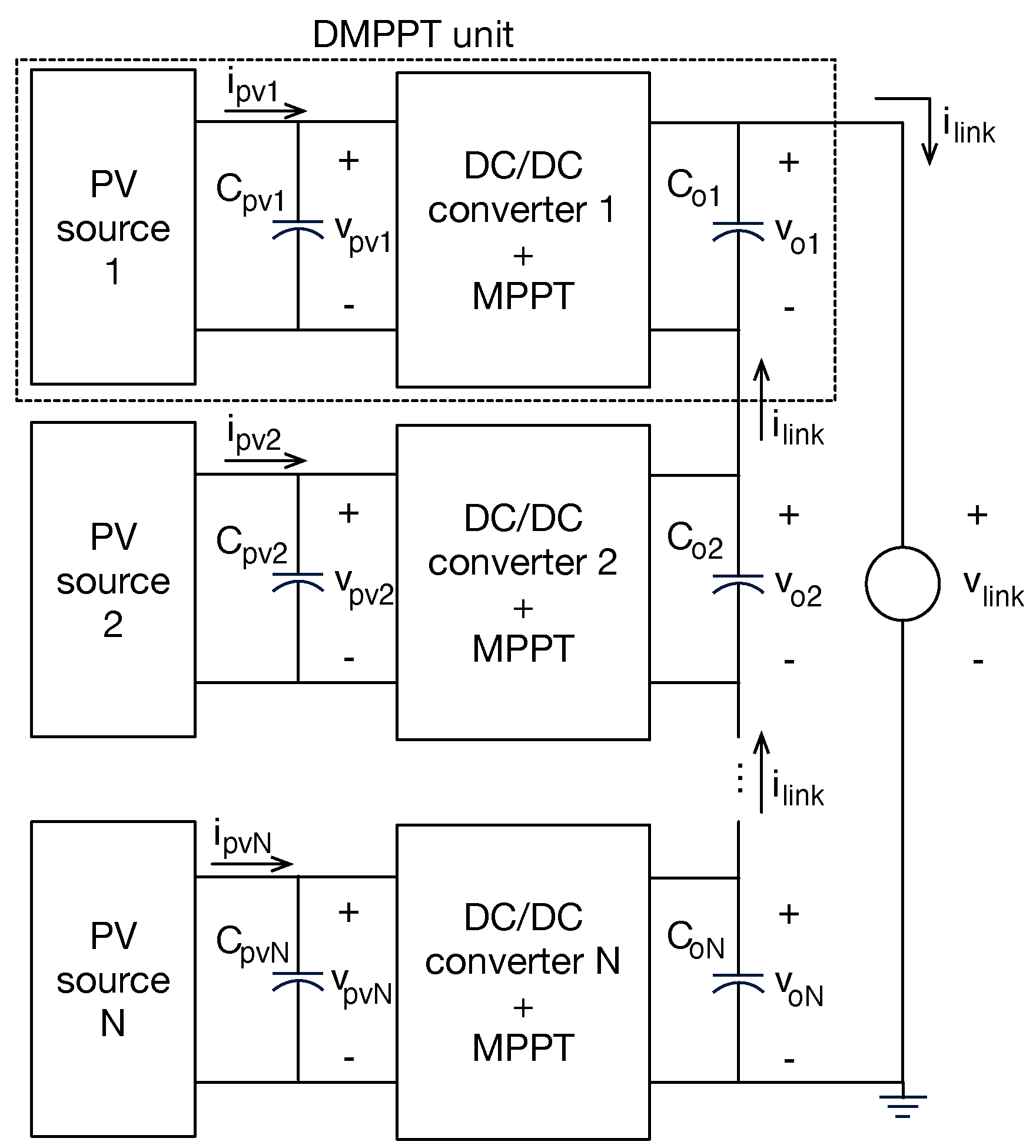
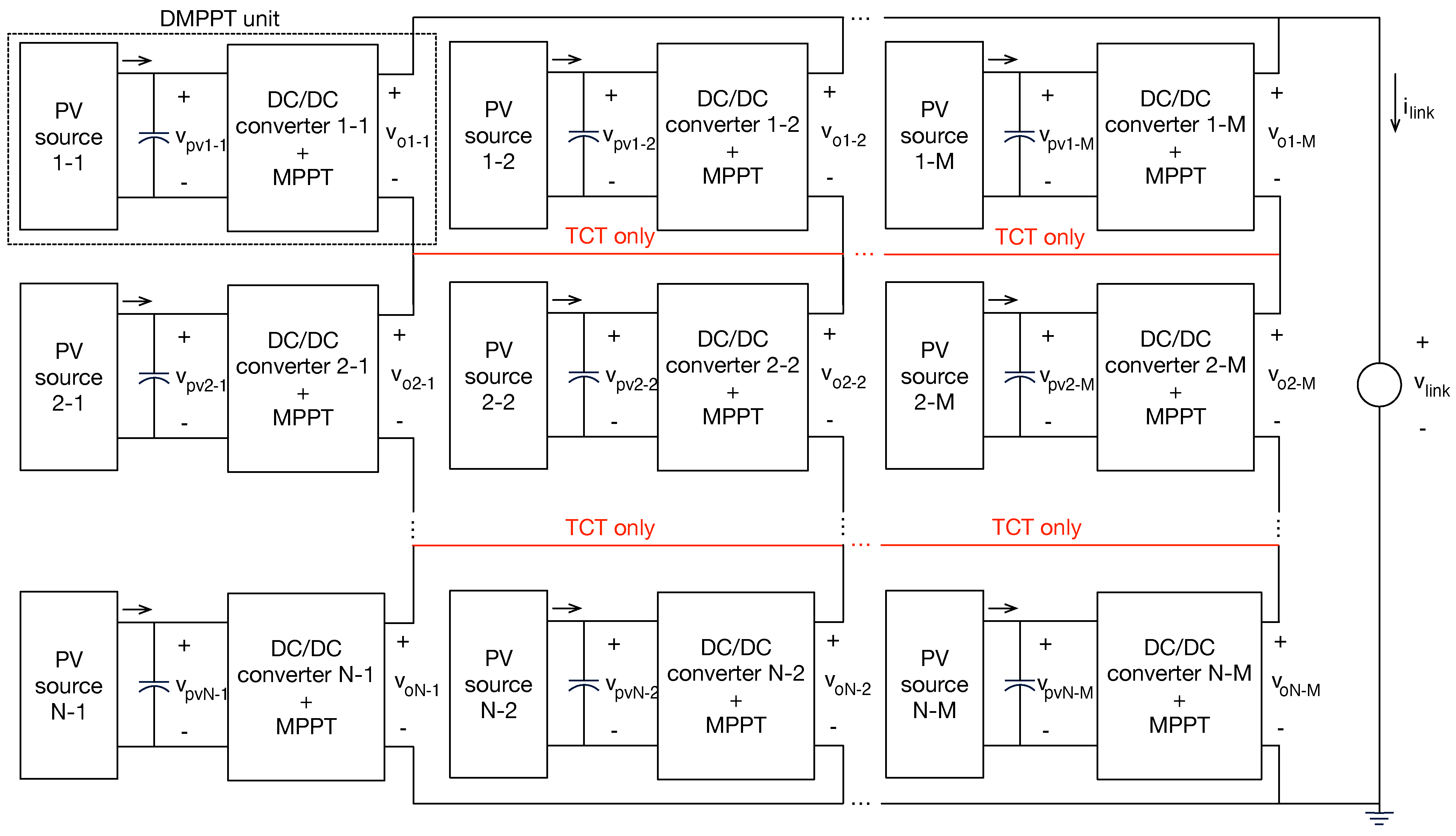
4.2. DMPPT Solutions for BIPV Systems

One of the first DMPPT solutions for BIPV systems was reported in [36], which is focused on designing smart PV modules for low-power PV generators, i.e., small number of cells connected in series. This solution adopts the classical DMPPT series-connection, in which the output terminals of the DMPPT converter are connected in series, thus providing an additional boosting factor. Since the series-connection of the smart PV modules distributes the total output voltage among all the DC/DC converters, a flyback-based converter is used to interface the PV source, thus enabling an output voltage higher than, equal to, or lower than the MPP voltage. This is a flexible approach, but it also introduces additional implementation complexity in comparison with the classical boost solution. Moreover, each smart PV module requires three control stages: an inner current PI controller, an outer PI (PV) voltage controller, and an MPPT (P&O) loop. Unfortunately, the design of those control systems is not discussed.
The review of single-phase grid-connected solar inverters, published in ref. [65], also discusses DMPPT solutions. In this case, the boost converter is also considered as the first option for imposing the MPPT action, since it is simple to implement, drive, and control. Then, following the discussion of ref. [36], the flyback converter is selected as the second option, which provides isolation and a flexible voltage conversion ratio. Since both solutions are focused on microinverters, no series-connection of DMPPT modules is considered, which removes one of the advantages of the flyback solution over the boost converter. In any case, the flexibility of adjusting the voltage-conversion ratio with the transformer turn-ratio enables the flyback converter to reach higher DC-link voltages at the expense of higher complexity and cost. Finally, the controller analysis is mainly focused on the inverter stage, but a high-frequency controller is required in the DC side to mitigate the 120 Hz oscillations present at the DC-link due to the grid-connection.
Two complementary works were focused on analyzing the effects of the output connection in DMPPT BIPV systems. The first one, reported in ref. [34], analyzes the cross-coupling effects between DMPPT modules when the output terminals of the DC/DC converters are connected in a Total-Cross-Tied (TCT) configuration. The second one, reported in ref. [31], analyzes the same problem for a series configuration of the output terminals of the converters. Both works are based on boost converters; thus, the DMPPT module is formed by the PV module, a boost converter, and a P&O algorithm for each module. The first work [34] was conducted to demonstrate the higher power production of DMPPT systems over CMPPT solutions; this work also shows the advantages of connecting the converters’ output terminals in TCT configuration over classical series and parallel options: the series-connection could impose low output voltages to the DC/DC converters with lower power production (caused by partial shading), thus making it difficult (or preventing) to reach the MPP condition of the PV modules. However, such a series-connection produces a boosting factor, hence reaching the DC-link voltage with a small voltage-conversion ratio for each DMPPT converter. Instead, the parallel connection of the DMPPT converter’s outputs requires a high voltage-conversion ratio because each converter must support the complete DC-link voltage, thus introducing high stress. Instead, the TCT connection provides a balance in the power generation by collecting some shaded DMPPT modules into rows, thus reducing the difference between the rows’ currents. Despite such results, the authors focused the second work [31] on the series-connection of DMPPT converters, including experimental validations. The most interesting part of this work concerns the mathematical expressions used to describe the cross-coupling effects, thus clarifying the phenomenon. Another interesting result concerns the verification of the second quadrant operation of PV modules even under DMPPT conditions: the partially shaded DMPPT sections could have the boost converter with low output voltage (lower than the PV voltage), which imposes a duty cycle equal to zero; under this condition the internal body-diode of the MOSFET is forward biassed, hence imposing a negative voltage to the PV module, forcing it to consume power and producing accelerated aging. In conclusion, the topics analyzed in refs. [31,34] are extremely important for DMPPT systems in BIPV applications due to the high probability of deep partial shading. Therefore, those topics are further discussed in Section 4.4 using simulations and mathematical analyses.
The integration of PV pantile roof tiles into buildings is explored in ref. [30], where a compact power stage is designed. Such a power converter is based on the boost topology, achieving efficiencies near to 95%. The integrated power stage also includes control and MPPT stages implemented in an ATtiny microcontroller, but no details about the control system structure or MPPT algorithm are given. In any case, from the system schematic it is concluded that the control system is based on a proportional gain, and the MPPT algorithm must be a P&O implementation. Another architectural integration is discussed in ref. [29], which is based on perovskite PV cells installed in the curved surfaces of BIPV applications. This paper suggests the adoption of a boost converter and a P&O algorithm to maximize the power production of each DMPPT section; this is particularly important for curve surfaces since each PV section is exposed to different irradiance values, thus producing a large partial-shading condition in the whole PV array. However, the paper does not discuss any high-frequency controller or the output connection of each DMPPT converter.
The work reported in ref. [66] presents an intermediate solution between CMPPT and DMPPT. This approach divides the complete PV array into strings, and each string is optimized by a semi-DMPPT microinverter. This work discusses the adoption of flyback-based MPPT converters in commercial PV microinverters and proposes a Quasi-Z-source series-resonant DC–DC converter to achieve a better dynamic range. However, no analysis of such a converter is provided, and the control system is not discussed. Instead, the MPPT solution is discussed in detail, which performs a voltage sweep to detect the Global MPP (GMPP) region, and a Local MPPT (LMPPT) algorithm to optimize the power production. This approach is needed since the semi-DMPPT strings suffer from the activation of bypass diodes in each string, hence a GMPPT algorithm is needed to avoid the operation at a Local MPP (LMPP), thus reducing the power losses caused by the partial-shading conditions in comparison with CMPPT systems.
A revision of common failures present in DMPPT systems for rooftop and BIPV installations is provided in ref. [93]. This paper also proposes a fault-tolerant DMPPT unit, formed by a non-inverting buck-boost converter and failure detection algorithms. In particular, this solution is able to support switch and sensor failures in the DMPPT unit, also providing a failure indicator for scheduling a maintenance routine. This solution adopts the buck-boost topology due to the flexibility provided in terms of voltage-conversion ratio: since the buck-boost topology is able to support output voltages higher than, equal to, or lower than the PV voltage, this solution enables one to connect any number of DMPPT modules in a string (series-connection), achieving the MPP of each module, thus avoiding the cross-coupling problems discussed in refs. [31,34] for DMPPT systems based on boost converters. Finally, the paper is mainly focused on failure mitigation; hence, no discussion is performed regarding the MPPT algorithm or the high-frequency controller, but the solution is flexible enough to support any control and MPPT approaches.
A particular BIPV integration, at the facade level, is discussed in ref. [39]. This solution describes a power electronics scheme to implement a DMPPT PV system with grid-connection, where the PV modules are thin-film technologies that can be customized to provide transparency and facade integration, but due to the building structure deep partial shading is always present. The paper considers boost converters interfacing each PV module, but the output terminals of those converters are connected in parallel to a DC-link. This strategy avoids the cross-coupling problems discussed in refs. [31,34] but requires a large voltage-conversion ratio in each boost converter, which could introduce higher stress to the semiconductors and passive elements. Moreover, due to the absence of cross-coupling problems, each boost converter is regulated using an IC MPPT algorithm with no high-frequency controller. The main problem of this approach is the possible interference of DC-link perturbations into the MPPT action, or the need of installing a large DC-link capacitor to ensure a low-voltage oscillation in the DC-link voltage.
The reliability of DC/DC converters for BIPV applications is discussed in ref. [94], where the failure rate of switches, capacitors, drivers, and other components is analyzed. This study provides useful guidelines for selecting components and designing the converters to reduce the failure rate of BIPV applications. This paper illustrates the reliability analyses with a BIPV example, which considers an Isolated-Interleaved Boost Converter (IIBC) to introduce galvanic isolation and simplify the driver since the switches are connected to the ground. The IIBC has the same driving simplicity in comparison with the boost and flyback converters, and it is simpler in comparison with the drivers needed for the buck-boost options (both inverting and non-inverting). In comparison with the boost option, the IIBC has a higher voltage-conversion ratio and galvanic isolation, but the flyback converter could provide the same characteristics. However, the IIBC has a redundant structure because the converter could keep interfacing the PV source with a failure in a single branch. Therefore, it is an interesting option for reliable BIPV installations. Finally, the paper does not discusses a high-frequency controller or the MPPT algorithm, which are needed to perform a DMPPT operation. Taking into account the interleaved structure and high-frequency transformer used in the IIBC, the control complexity is higher in comparison with the classical DMPPT approaches based on boost, flyback, or buck-boost topologies.
The work reported in ref. [95] is also focused on analyzing the IIBC and boost converters, but in this case the comparison is contextualized in facade BIPV applications where solar cells are inserted into the building envelope. This work also analyzes the effect of the bus voltage in the converter selection and efficiency, which is useful to improve DMPPT installations for BIPV systems. The structures discussed in the paper have a parallel output convection for the DMPPT converters, which constraints the converters’ voltage-conversion ratio to boosting factors; therefore, some of the paper’s conclusions are difficult to extend to the series and TCT output connections discussed in refs. [31,34]. In any case, the detailed analysis presented for both IIBC and boost converters could be useful for both components and topology selection, complementing the guidelines given in ref. [94]. Unfortunately, since the work is concentrated on the topology analysis, no discussion is performed in terms of the MPPT algorithm or high-frequency controller.
The reliability of BIPV systems is also addressed in ref. [33], but in this case the DMPPT architecture is implemented using microinverters. The solution proposed in this paper is focused on a single-phase and Buck-Boost Single Stage Microinverter (BBSM), which is designed to provide high reliability by optimizing the number of active and passive elements. This solution is applicable to building AC distribution networks; hence, it is not useful for BIPV DC microgrids such as light-to-light installations based on LEDs. However, the use of PV microgrids is a useful practice to introduce BIPV solutions using the existing AC network. The paper discusses the microinverter topology, presenting the operation modes and analyzing both the switching sequence and the power losses, thus providing useful guides for practical implementations. Similar to the solutions discussed before, no analysis of the control system is given, which could introduce problems when perturbations occur in the building AC network. Finally, the microinverter uses the classical P&O MPPT algorithm.
A different type of DMPPT for BIPV systems, named Differential Power Processing (DPP), is discussed in ref. [67]. In such an approach, the difference in the current of the PV modules, due to partial shading, is distributed to avoid the activation of bypass diodes. The classical DPP systems require almost the same switches in comparison with other DMPPT approaches, but no voltage-conversion ratio is provided; thus, a central converter is needed to adjust the overall voltage of the PV string. This solution is useful to mitigate partial shading effects without changing the original PV inverter, since the original MPPT controller optimizes the DPP voltage without any modification. The solution proposed in this paper aims to reduce the total number of switches by using an LLC-resonant voltage-multiplier inverter with multiple inputs, which equalizes the voltages of the modules in the DPP string, contrasting the performance with a flyback solution. The authors claim that no control or MPPT algorithm is needed since the voltages at the PV modules are set to the same value, which is selected equal to the average MPP voltage for different irradiance values. However, such an approach has two problems: first, the PV power of all the modules is not maximized since no operation at the MPPs is ensured; second, any perturbation on the DC-link could be transferred to the PV modules, thus degrading the power extraction.
A review of partial-shading mitigation solutions for grid-connected PV systems is provided in ref. [20], where a section of such a revision is focused on BIPV applications. This work is a useful entry point for partial-shading mitigation studies, since it provides a detailed background on the partial-shading phenomenon, the PV array configurations tested for reducing the power degradation, the topologies for DMPPT (series, parallel, DPP), and some power converters for DMPPT implementations. This paper also provides simulations to compare the performance of array reconfiguration and DMPPT at the module level, but no comparison is given for the different types of DMPPT connections or power stages. In particular, the boost and flyback converters are analyzed due to their wide use in several commercial solutions, but no particular analyses are given for BIPV systems. Similarly, several MPPT solutions are described, but there is no analysis on the specific characteristics needed for BIPV applications.
Another work focused on thin-film BIPV systems is reported in ref. [42], which proposes a DMPPT unit based on a boost converter, a cascade control system, and an MPPT algorithm. The paper presents a model for thin-film PV sources, which is used to analyze the behavior of the MPPT algorithm needed to improve the tracking speed. Then, the power stage is modeled, which considerers the operation of the boost converter in both Continuous Conduction Mode (CCM) and Discontinuous Conduction Mode (DCM), which is useful for the low short-circuit conditions present in thin-film PV modules. The proposed MPPT algorithm is very similar to the classical P&O solution, but it provides a variable step-size to speed up the tracking of the optimal operation condition. The most useful part of such an analysis is the study of the PV voltage dynamics in both CCM and DCM, which is used to design the sampling period of the MPPT algorithm to ensure stability. Finally, a high-frequency cascade control system is designed, which also includes a correction factor for DCM operation. The main limitation of this control system concerns the adoption of a resistive model for the load, which is a particular case in BIPV systems (a fixed-impedance load); instead, a more realistic approach could have a Thevenin model since grid-connected inverters and battery chargers (from DC microgrids) always regulate the DC-link voltage, with some unavoidable perturbations.
A hybrid approach for DMPPT solutions in BIPV systems was designed in ref. [96], where the power processing uses distributed power converters equal to traditional DMPPT, but the MPPT action is centralized in a single processing unit equal to traditional CMPPT. This hybrid approach is intended to reduce the size and complexity of each DMPPT unit, since the processing algorithms are executed in a central computing unit, which also enables remote monitoring for diagnosis purposes. The communication between the DMPPT units and the processing machine is performed with XBee 900 MHz RF modules (Digi International, Hopkinsn, MN, USA), which avoids the need of cables and provides placement flexibility. Each DMPPT unit is formed by a classical boost converter and both electrical (current and voltage) and environmental (irradiance and temperature) sensors. Such information is transferred to the central computing machine, which implements a Sliding-Mode Controller (SMC) to regulate the PV voltage of each DMPPT unit. Moreover, the central processing unit uses polynomial expressions to estimate both the maximum power P m p p and MPP current I m p p of each module from the irradiance and temperature measurements, which is used to estimate the reference for the SMC as V r e f = P m p p / I m p p . This MPPT approach is fast, but it only works on PV modules previously parameterized, which requires several off-line experimental tests. Similarly, after an extended operation time, the aging of the PV modules changes the MPP locations; therefore, to ensure the maximum power extraction, the modules must be parameterized again to correct both polynomial equations. Finally, both the DMPPT model and experiments consider a resistive load, which is a particular condition not common in BIPV systems, since DC-link voltage regulation is present in DC microgrids and grid-connection.

4.3. Synthesis and Discussion of the BIPV Approaches

The previous revision of CMPPT and DMPPT solutions in BIPV applications shows a clear interest in designing new solutions to reduce the impact of partial shading conditions. Figure 11 shows the cumulative number of papers of CMPPT and DMPPT solutions published between 2018 and 2023, where a higher increment in DMPPT publications over CMPPT publications is observed. This is expected since, under partial shading, DMPPT solutions are able to extract higher energy in comparison with CMPPT options due to the possibility to set each PV module to its individual MPP condition. However, under low mismatching conditions (near uniform irradiance) CMPPT solutions could be more efficient. In addition, DMPPT solutions are more complex, since they require more elements and cross-coupling between DMPPT units could prevent the operation at the MPP condition. Therefore, the selection of CMPPT or DMPPT solutions highly depends on the amount of mismatching present in the PV array.
Table 10 summarizes the CMPPT and DMPPT solutions discussed in this section, describing the adopted power converter, control system, and MPPT algorithm. Moreover, the DMPPT solutions are classified into different sub-types to provide an easier selection depending on the particular application. From the data in Table 10, it can be seen that 64% of the solutions are DMPPT, while 36% are CMPPT; in addition, Figure 11 shows a higher interest for DMPPT applications in recent years. From those DMPPT solutions, 25% have series connection of the converters’ outputs, which provides a boosting factor that reduces the voltage-conversion ratio required for each DMPPT converter. The parallel connection of DMPPT outputs is the second DMPPT sub-type with more uses (18.8%), since this connection avoids the detrimental cross-coupling effects discussed in refs. [31,34] that prevent the operation at the global MPP condition. Moreover, it is easier to implement due to the existence of a common ground for all DMPPT units (power stage, drivers, and sensors). However, the parallel sub-type requires a high voltage-conversion ratio for each DMPPT converter, which introduces high stress to the elements and increases the system costs. Instead, only 6.3% of the DMPPT solutions have a TCT connection of the converters’ output, which could reduce the detrimental cross-coupling effects (as the parallel connection) and provides a boosting factor (as the serial connection). Therefore, the TCT sub-type must be further investigated. The next sub-type of DMPPT solutions are microinverters (12.5%), which could be based on single- or double-stage topologies. The ones based on double-stage systems require an MPPT converter, a DC-link, and a grid-connected inverter, while the single-stage ones have a more complex converter in charge of both actions. In any case, the components of the microinverters must be able to support higher voltages and are only useful for BIPV applications with AC buses. The string semi-DMPPT has also been used in 12.5% of the DMPPT solutions, where the PV array is divided into PV strings to distribute the MPPT action. This is an intermediate DMPPT/CMPPT solution, since bypass diodes are activated as in CMPPT solutions; hence, dynamic reconfiguration is a suitable option to mitigate the partial shading effects, but there is no interaction between PV strings as in DMPPT solutions. Finally, the converters’ output are connected in parallel to a common DC-link, which could interact with DC-loads (such as LEDs) or grid-connected inverters. The DPP approach was used in 6.3% of the DMPPT solutions, which uses converters with less power requirements since only the power difference among PV modules is processed. Therefore, the power stages are cheaper and easier to implement. However, DPP systems do not provide any boosting factor and require a central MPPT converter to achieve the MPP condition in all the modules. Hence, similar to the string semi-DMPPT, DPP could interact with DC-loads or grid-connected inverters. Finally, Table 10 has a particular DMPPT sub-type named general, with 18.8% of the cases. The solutions in this category do not provide detailed information to determine the exact DMPPT sub-type and are solutions intended for any DMPPT connection. However, as discussed before, the type of connection could affect the MPPT capability of the DMPPT unit; hence, those general solutions must be analyzed in detail for the particular connection scheme used in the DMPPT installation.
The second step in designing BIPV power systems consist of selecting the power converter that performs the MPPT action on the PV modules. The data in Table 10 show that 56.7% of the solutions use the classical boost converter (Figure 12) to execute the MPP tracking, and such a high rate of selection occurs in both CMPPT and DMPPT types. The main advantages of the boost converters for BIPV applications are its simplicity and low cost, grounded driver, and acceptable voltage-conversion ratio. Moreover, due to the small size, it can be integrated into the back of the PV modules, thus saving space. The boost converter is ideal for CMPPT since it provides a boosting factor usable to reach the DC-link voltage, but in DMPPT-series solutions the output voltage could suffer cross-coupling effects, thus preventing the extraction of the maximum available power. Finally, the boost converter does not provide any galvanic isolation.
The second most used converter in the reviewed BIPV solutions is the flyback topology (16.7%) depicted in Figure 13, which provides two main advantages over the boost converter: first, it provides galvanic isolation, thus ensuring a higher level of protection; and second, it provides a more flexible voltage-conversion ratio. This flexibility in the input–output voltage relation is usable for both CMPPT and DMPPT approaches. In CMPPT applications, the turn-ratio (n) of the flyback transformer can be adjusted to provide a high output voltage without saturating the duty-cycle, which is needed to ensure high-precision on the voltage control and MPPT action. However, the high turn-ratio of the transformer also reduces the converter efficiency; hence, a trade-off must be accomplished. Such a high voltage-conversion ratio is also useful in DMPPT applications with parallel output connection (parallel sub-type), microinverter sub-type, and string semi-DMPPT sub-type since a high DC-link voltage is usually needed. However, DMPPT applications with a series output connection (series sub-type) and a high number of modules could require a converter’s output voltage to be lower (or equal) to the PV voltage; hence, the turn-ratio of the transformer can be set to 1, enabling the flyback converter to reach the MPP condition since it behaves like a buck-boost topology.
The converter third option (10%) is the interleaved boost converters, which provide the same advantages of the boost converter with additional redundancy that improves the overall system reliability; this is the case of the interleaved boost converter with three branches depicted in Figure 14. Moreover, some of the interleaved topologies could increase efficiency; others could increase the voltage-conversion ratio and provide galvanic isolation, which is the case of the isolated-interleaved boost converter depicted in Figure 15. However, the increment in the converter complexity and cost is, at least, doubled with respect to the classical boost converter (proportional to the number of branches); hence, its adoption must be clearly justified with cost/effectiveness analyses. The interleaved boost topologies could also provide a ripple cancellation feature for the PV side, which reduces the input capacitance of the converter, but this requires more complex control systems. From Table 10, it can be seen that interleaved boost converters are used in both CMPPT and DMPPT applications, but they are mostly adopted in DMPPT systems to improve reliability and efficiency; however, their higher size (location problem) and cost (viability problem) must be analyzed.
The fourth converter option (3.3%) in Table 10 is the Dual-Active Bridge (DAB) converter depicted in Figure 16, which provides several advantages for CMPPT systems. First, the high-frequency transformer allows one to reach high voltage-conversion ratios without saturating the control signal; second, the converter provides galvanic isolation; third, a proper implementation could provide high efficiency. However, it also has some drawbacks: it is a large and complex converter requiring a high-frequency transformer; both bridges must be controlled with duty cycles equal to 0.5 to ensure null average current in the transformer (high efficiency), and the power flow is defined with the phase-shift between both bridge activation signals, thus introducing a high control complexity. Therefore, the adoption of the DAB converter must be justified, mainly, by the requirement of galvanic isolation or high voltage-conversion ratios.
Table 10 shows that buck-boost converters (Figure 17 depicts a non-inverting buck-boost topology) are exclusively used in DMPPT systems (with 3.3%), which is expected since CMPPT systems require a voltage-conversion ratio higher than one; thus, the boost converter is a better option since it provides a higher efficiency. Instead, the cross-coupling problem of DMPPT systems, which could impose output voltages in the DMPPT converter lower than the MPP voltage, can produce high power losses; such a problem could be solved by adopting buck-boost converters. However, the low efficiency of the buck-boost converter, in comparison with the boost option, makes critical the analysis of the cross-coupling condition before adopting buck-boost topologies over boost ones in DMPPT applications. In BIPV applications, this topic has only be discussed in refs. [31,34] for boost converters, and no analysis has been found for buck-boost or flyback topologies, including the impact of the converter efficiency. Therefore, to provide a more complete framework, Section 4.4 provides a detailed analysis of the cross-coupling phenomenon, analyzing the performance of boost, buck-boost, and flyback converters under such a condition.
Finally, other complex converters (10% of Table 10) have been proposed to address specific conditions, but no particular advantages over the previous five topologies are observed. In any case, the adoption of such additional converters could be supported by component availability or size constraints, but in the papers those analyzes are not given.
Concerning the high-frequency controllers for BIPV systems, Table 10 shows that 69.2% of the solutions do not consider any control system different from the MPPT algorithm, which makes those solutions susceptible to be affect by load perturbations. For example, 67% of the CMPPT solutions do not consider any PV voltage controller; hence, a grid-connection produces a voltage oscillation at double the grid frequency, which must be damped by a large DC-link capacitor, otherwise such an oscillation could interfere with the MPPT operation, thus avoiding the maximum power extraction. Similarly, 75% of the DMPPT solutions do not consider any PV voltage controller, which makes those solutions prone to be affected by load perturbations (e.g., grid-connection of the whole DMPPT system) or the operation of other converters in the DMPPT structure. In DMPPT with Series or TCT output connections, the change in the PV power of one module also changes the output voltage of that converter, which produces a chain reaction affecting the output voltages of all the series-connected converters, thus perturbing the operation point of all the DMPPT units. Therefore, the lack of PV voltage controllers ensures that multiple perturbations affect all the DC/DC converters, which reduces the overall power production.
A small number of the BIPV solutions in Table 10 (30.8%) have recognized the need of regulating the PV voltage. The CMPPT solutions considering a high-frequency voltage controller (only 33%) exclusively adopt PI voltage topologies, which are simple to implement but only ensure the desired performance for a particular operation condition (design irradiance); for other operation conditions, the settling-time and overshoot of the PV voltage are different. In any case, it is possible to design such a PI controller to ensure the system stability by selecting the worst-case condition, which usually corresponds to the highest irradiance obtained in the location. The DMPPT solutions that consider a voltage controller (only 25%) have more options: one solution adopts a Proportional (P) controller, which also ensures the desired performance at a single operation condition, but it is very simple to implement; in fact, it was implemented in a digital processing platform using only the resources available in the microprocessor performing the MPPT action. Another two solutions use cascade voltage-current loops regulated with PI controllers, where the inner current loop regulates an inductor (or magnetizing) current, and the voltage loop regulates the PV voltage by acting on the current loop reference. This structure is used in DMPPT boost and flyback topologies to ensure stability since the current loop behaves as a current source; hence, the voltage controller is easily regulated with a PI controller, and the PV voltage behaves as a first-order system, thus providing a smother waveform in comparison with single P or PI voltage controllers. However, the current-voltage cascade structure requires an additional current sensor, which introduces complexity and additional costs. Therefore, adopting such a cascade structure is justified in DMPPT systems with permanent perturbations, like Series and TCT DMPPT applications; instead, for parallel DMPPT installations the single P or PI voltage controllers could be enough. The last type of control systems used in DMPPT applications is a Sliding-Mode Controller (SMC) regulating the PV voltage. This type of controllers is widely adopted in classical PV systems, but its use is very limited in BIPV applications. The main reason for this limited use is the requirement of nonlinear analyses to reach a useful sliding-surface that guarantees global stability. Moreover, some implementations of SMC can be done with PWM circuits, while others require a hysteresis comparator, which introduces additional complexity. However, the SMC is the only technique listed in Table 10 that can ensure the same performance (and global stability) to the DMPPT system; hence, it is worthy of study for more BIPV cases. Finally, this control system revision shows that there is an opportunity in designing new control systems, taking into account the particular characteristics of BIPV systems, with the aim of guaranteeing global stability and a consistent performance in all operation conditions.
The last BIPV characteristic reported in Table 10 is the MPPT algorithm. Taking into account the importance of the MPPT action in PV systems, it is remarkable that 40% of the BIPV solutions reported in Table 10 do not discuss any MPPT algorithm (marked as N/A in the table). This is caused by the focus of each paper, which in some cases is the power converter, the control system, or the application case; hence, no attention is devoted to the MPPT algorithm. For the other 60% of cases, more than half of the solutions adopt the Perturb and Observe (P&O) algorithm, which is a simple hill-climbing solution aimed at detecting the perturbation direction that increases the produced power. The wide adoption of this P&O solution resides in its simplicity and cheap implementation, which could reach high MPPT efficiency in uniform conditions if the perturbation period and amplitude are correctly selected. However, it is not reliable for partial-shading conditions. Therefore, it is used with more frequency in DMPPT applications, where each DMPPT unit has a single maximum power point, thus requiring a single P&O unit dedicated to each PV module. The next MPPT solution is Incremental Conductance (IC), which is used in 15.4% of the solutions. The IC algorithm tracks the conditions where the magnitude of the instantaneous conductance (I/V) is equal to the magnitude of the incremental conductance (dI/dV), but with the opposite sign, since such a condition corresponds to the peak value of the power vs. voltage curve. The main problem of the IC solution is the noise amplification in the derivative used to calculate the incremental conductance; hence, current and voltage filters must be added to avoid a wrong operation. Moreover, the IC is also unreliable in partial-shading conditions, so it is efficient only in DMPPT implementations. Figure 18 shows the flowcharts for the digital implementations of the P&O and IC algorithms, where Δ V p v ( k ) is the change introduced on the voltage reference in each cycle of the algorithms, and T a is the algorithms period; the correct selection of both parameters is essential to maximize the power extraction from the PV source.
The Reserve Generation Algorithm (RGA) is designed to deload a CMPPT system in order to avoid large changes in the active power when irradiance changes occur, which is needed to provide frequency support to the grid. This is complemented with a strategy to detect partial-shading conditions, which triggers the RGA to increase or decrease the power generated by the PV array. This is a very particular application case; hence, the usability of the RGA in general BIPV systems is very limited. Another solution is focused on string semi-DMPPT, where bypass diodes could become active, so a voltage sweep is performed to the PV array to detect the location of the Global Maximum Power Point (GMPP), then a local MPPT algorithm (which could be a P&O or IC) is used to fine-tune the PV voltage to reach the GMPP. The main drawback of this type of solution is the energy losses occurring during the sweep action and the complexity in detecting the optimal frequency to perform such a sweep. The next MPPT algorithm reported in Table 10 is the three-stage variable step, which is similar to the P&O algorithm in which a variable perturbation size is used to speed-up the tracking of the MPP. Moreover, this solution provides design equations to calculate the optimal perturbation size, which is needed to ensure the global stability of the BIPV system. However, this solution is also susceptible to be trapped in a local MPP; hence, it is only efficient for DMPPT installations. The final MPPT solution is based on polynomial expressions used to predict the MPP power and current; hence, it is not a tracking algorithm, instead it is an estimation algorithm. It requires one to pre-calculate both polynomial expressions using experimental (or datasheet) data, which is time consuming, and the resulting equations are valid only for the parameterized modules. Moreover, in operation it needs to measure both irradiance and temperature, thus increasing the system costs and size. The main drawback of this approach is caused by the modules aging, because the MPP conditions of the modules change, thus making the polynomial equations less accurate, which reduces the power production since the PV system operates far from the real MPP condition. In any case, this approach also has some advantages: first, it is very fast because no tracking is performed; thus, there are no dynamic losses as occurs in both P&O and IC solutions; and second, the irradiance, temperature, and power production data could be used for the diagnosis of the module health. In addition, since this solution is based on polynomial expressions for single modules, it is only usable for DMPPT installations. Finally, it is observed that more efforts are needed to design MPPT algorithms with global MPP detection for the array in CMPPT solutions, and multivariable algorithms could be designed to improve the speed of DMPPT solutions in reaching the global MPP of the whole system.

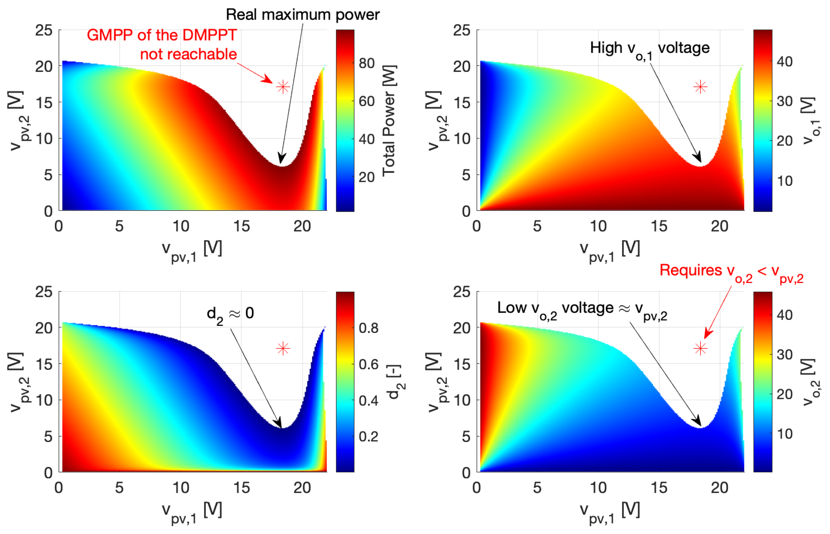
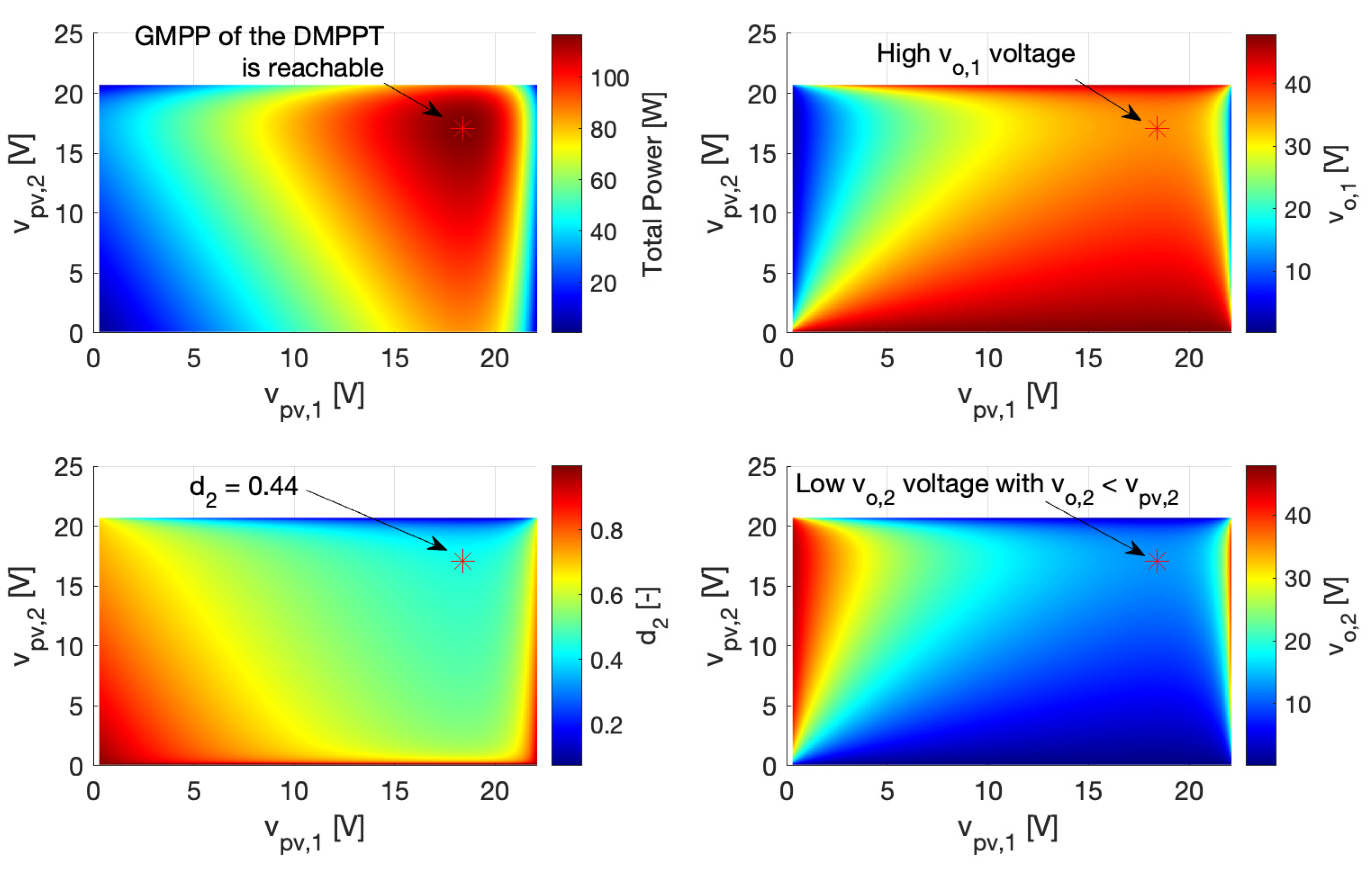
4.4. Discussion of the Cross-Coupling Problem in DMPPT Solutions

The cross-coupling problem occurs in DMPPT systems sharing the DC-link voltage, which are mainly Series and TCT sub-types. Figure 19 shows the structure of a DMPPT with series connection at the converters’ outputs (Series sub-type), where all the DMPPT units share the DC-link voltage v l i n k and have the same output current i l i n k .
The voltage sharing condition in the DMPPT system of Figure 19 is analyzed as follows. The total power delivered to the DC-link, named P l i n k , is equal to the sum of the power delivered by each DMPPT unit ( P o j = v p v j · i p v j , with j = 1 , 2 , N ), as reported in (17), and using the voltage Kirchhoff law in the output capacitors, the DC-link voltage is the sum of the output capacitor voltages, as given in (18).
P l i n k = j = 1 N P o j
v l i n k = j = 1 N v o j
From Figure 19, it can be seen that both DC-link and DMPPT units have the same current i l i n k , so the balance in the delivered power is the same one observed at the output voltages. Therefore, the output voltage v o k in the k t h DMPPT unit depends on the delivered power P o k , the overall power of the system, and the overall DC-link voltage, as follows:
v o k = v l i n k · P o k j = 1 N P o j
The previous expression leads to defining the cross-coupling conditions:
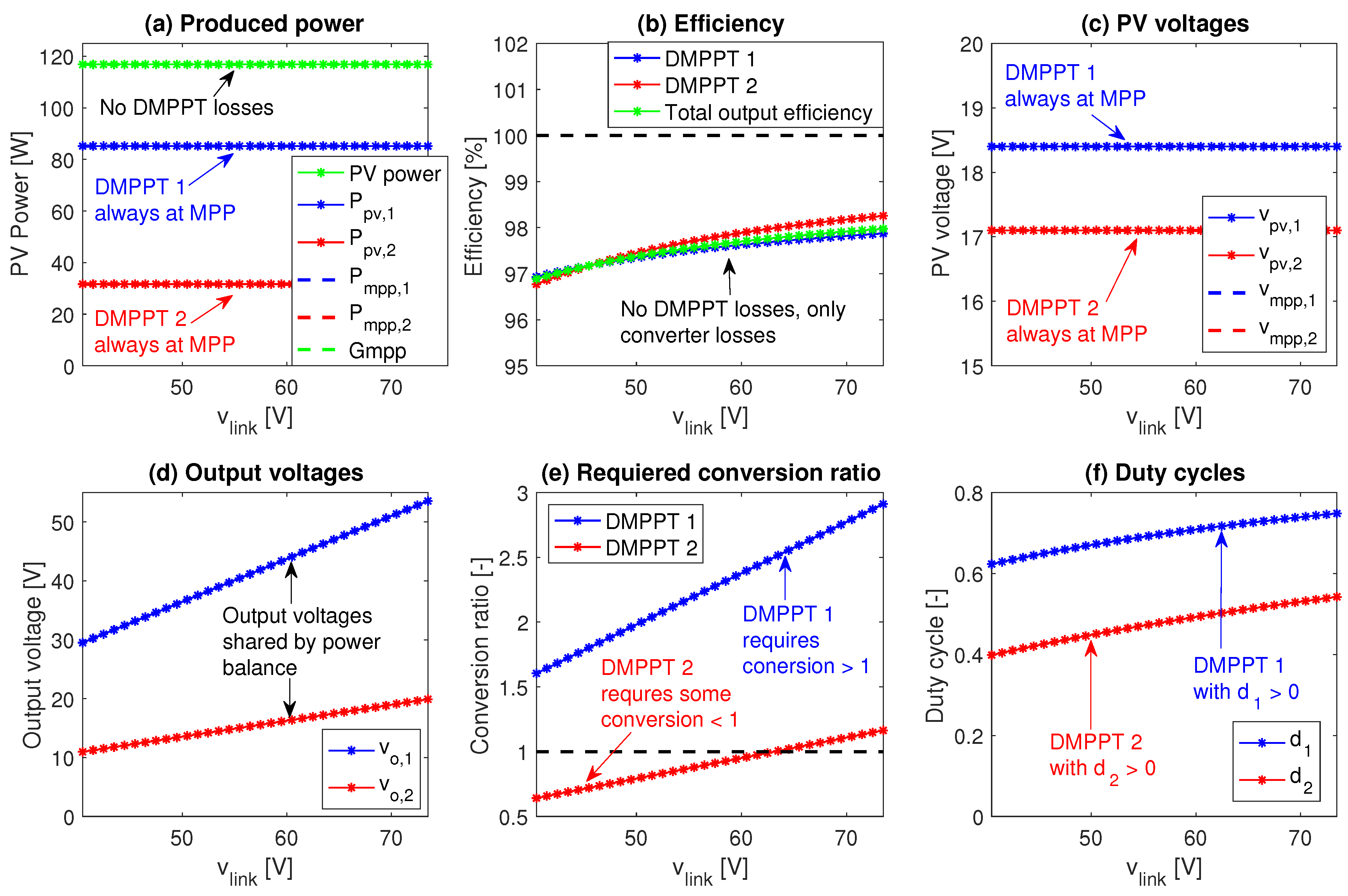
  • The output voltage of a DMPPT unit depends on the power balance between all the DMPPT units; hence, it could be changed by irradiance perturbations on the other DMPPT units.
  • Depending on the power balance between all the DMPPT units, a partially-shaded DMPPT unit could have an output voltage lower than the PV voltage.
The analysis of this cross-coupling problem in BIPV systems was discussed in refs. [31,34], only considering boost-based DMPPT units, but the impact of the converter’s efficiency is missed. Moreover, DMPPT units based on buck-boost or flyback converters must also be analyzed, since those topologies can support output voltages equal to or lower than the PV voltage. Therefore, the following subsections analyze the behavior of boost and buck-boost/flyback DMPPT units when cross-coupling occurs, including the converters’ efficiency.

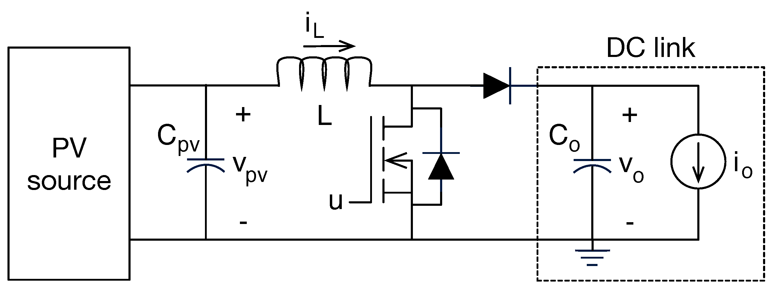
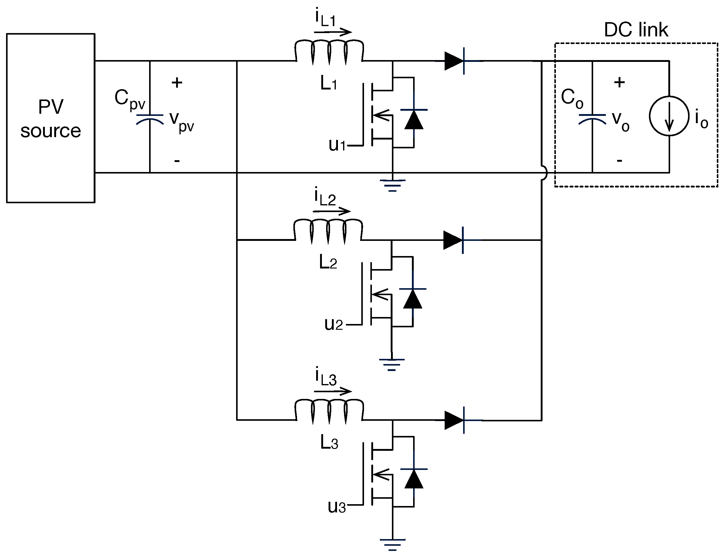
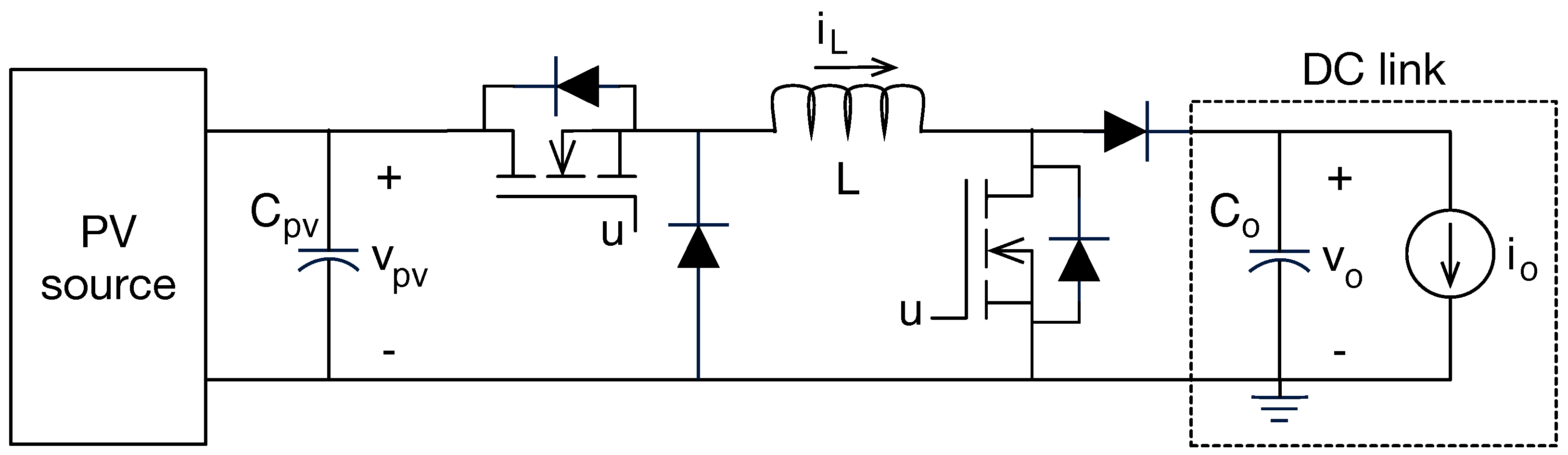
4.4.1. Boost-Based DMPPT Units

From Figure 12 it can be seen that the converter main losses can be lumped into a resistance R L in series with the inductor, which includes both the inductance and semiconductors losses. From the circuit analysis, the steady-state inductor current given in (20) can be obtained, which produces the power losses given in (21) and imposes the duty cycle given in (22) for a particular output voltage v o .
i L , b o o s t = i p v
P L , b o o s t = i p v 2 · R L
d b o o s t = v p v R L · i p v v o
The evaluation of the boost-based DMPPT unit under cross-coupling conditions is performed considering BP585 PV panels with the following STC parameters: short-circuit current i s c = 5 A, MPP power P m p p = 85 W, MPP voltage v m p p = 18 V, and MPP current i m p p = 4.72 A. Moreover, the converters are considered with inductors supporting up to 10 A and with an average series resistances of 40 m Ω (e.g., inductor PA4349.104ANLT, 100 μ H ), 12 A semiconductors with average on-resistances of 3.2 m Ω (e.g., MOSFET AOB290L), and including additional 1 m Ω losses in the input/output connectors. Those realistic conditions lead to lumped resistances R L = 47.4 m Ω for the numerical analyses. Those simulation parameters are summarized in Table 11. Finally, the previous expressions and the PV model reported in ref. [68] were used to simulate the DMPPT system in MATLAB (version 2024b).
The first simulation considers two boost-based DMPPT modules connected in series under partial-shading conditions, thus following the structure presented in Figure 19, where the first module is fully irradiated at 1000 W/m2, while the second one has a shade that reduces the effective irradiance to 400 W/m2. Moreover, the DC-link voltage is set to 48 V, which in uniform conditions requires the output voltages of both DMPPT modules to be 24 V, which is enough for the operation of the boost converters. However, applying Equation (19) shows that the output voltage of the second DMPPT unit for MPP operation ( v p v , 2 = 17.1 V) is v o , 2 = 13.7 V, which is not possible to reach with a boost converter since v p v , 2 v o , 2 is a physical constraint. Then, all possible operation points of this DMPPT system were simulated in MATLAB, and the results are reported in Figure 20. The top-left figure shows the total power achieved by the DMPPT system, where the real (achievable) maximum combined power is 97.47 W with v p v , 1 = 18 V and v p v , 2 = 5.9 V. The same figure shows the theoretical global DMPPT power ( G M P P = 116.83 W) calculated as the sum of P m p p in each module, which is not reachable since it requires v p v , 1 = 18 V and v p v , 2 = 17.1 V; therefore, this boost-based solution only extracts 83.4 % of the maximum available power.
The top-right side of Figure 20 shows the output voltage of the first DMPPT unit, which, at the real maximum power point, is v o , 1 = 42.1 V, thus supporting 87.7 % of the DC-link voltage. Similarly, the bottom-right side of the figure shows the output voltage of the second DMPPT unit, which, at the real maximum power point, is v o , 2 = 5.9 V. Such an output voltage requires the duty cycle d 2 depicted at the bottom-left of the figure, where, at the real maximum power point, is d 2 0 ; hence, no tracking in the second DMPPT unit is possible. In conclusion, for the partial-shading conditions and DC-link voltage of this first simulation, the series DMPPT solution based on boost converters is unable to extract the maximum possible power due to the cross-coupling problem, only reaching an MPP efficiency of 83.4 % . It must be pointed out that such an efficiency only takes into account the power produced by the PV modules, so the power losses in the DC/DC converters are not considered in this first analysis.
The next simulation was performed with the same PV conditions but changing the DC-link voltage, and also including the power losses in the boost converters. The simulation results are reported in Figure 21, where the DC-link voltage v l i n k is changed from 40 V to 74 V, while the partial-shading conditions remain constant. From Figure 21a, it is observed that the first DMPPT unit always operates at the MPP condition ( P p v , 1 = P m p p , 1 ), hence producing the maximum power. Instead, for DC-link voltages lower than 60 V the second DMPPT unit is not able to reach the MPP condition ( P p v , 2 < P m p p , 2 ), which prevents the complete DMPPT system from extracting the maximum available power ( P V p o w e r < G m p p ). For DC-link voltages higher than 60 V, both DMPPT units are able to reach the MPP condition; hence, the DMPPT system extracts the maximum power from the PV sources.
Figure 21b shows the output efficiency of the DMPPT units and system. For any DC-link voltage, DMPPT 1 has a constant efficiency of 98.8%, while DMPPT 2 suffers the cross-coupling losses for DC-link voltages lower than 60 V, where the efficiency drops significantly, thus reducing the overall efficiency to less than 75% in some cases. However, for DC-link voltages higher than 60 V the total output efficiency is near 99%, where no cross-coupling losses occur. Figure 21c clarifies that DMPPT 1 always reaches the MPP voltage, while DMPPT 2 must operate far from the MPP voltage when v l i n k < 60 V. Figure 21d shows the DC-link voltage distribution between the two DMPPT units, and Figure 21e reports the voltage-conversion ratios of both DMPPT units, where DMPPT 1 is always in boost mode (operating correctly), while DMPPT 2 is forced to operate at a unitary or lower (due to losses) conversion ratio, thus preventing the MPPT operation. Finally, Figure 21f reports the duty cycle of the DMPPT units, where v l i n k < 60 V saturates the DMPPT 2 duty cycle to d 2 = 0 , which prevents such a DMPPT unit from reaching the MPP condition.
The previous simulations show that the series connection of DMPPT units makes the system susceptible to cross-coupling losses, which in this example could reach 25 % for low DC-link voltages. Instead, for large DC-link voltages the cross-coupling losses are not present since the DMPPT units have enough output voltage to operate with practical duty cycles. However, with a larger number of series-connected DMPPT units, a partial shading of a single PV source could produce a very low output voltage, thus reaching the conditions for cross-coupling losses; hence, each particular system must be analyzed. This situation is illustrated in Section 4.4.3 with simulations of a large system formed by 18 DMPPT units.

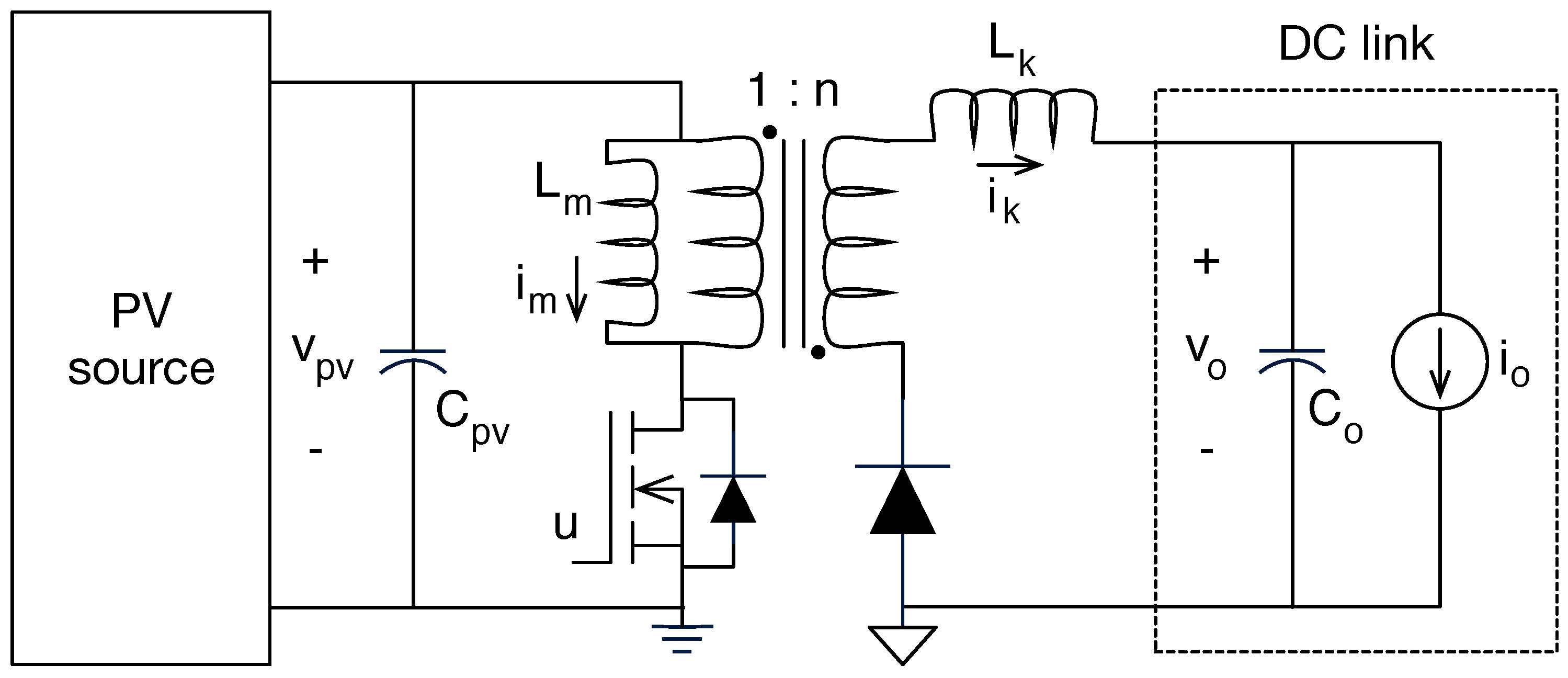
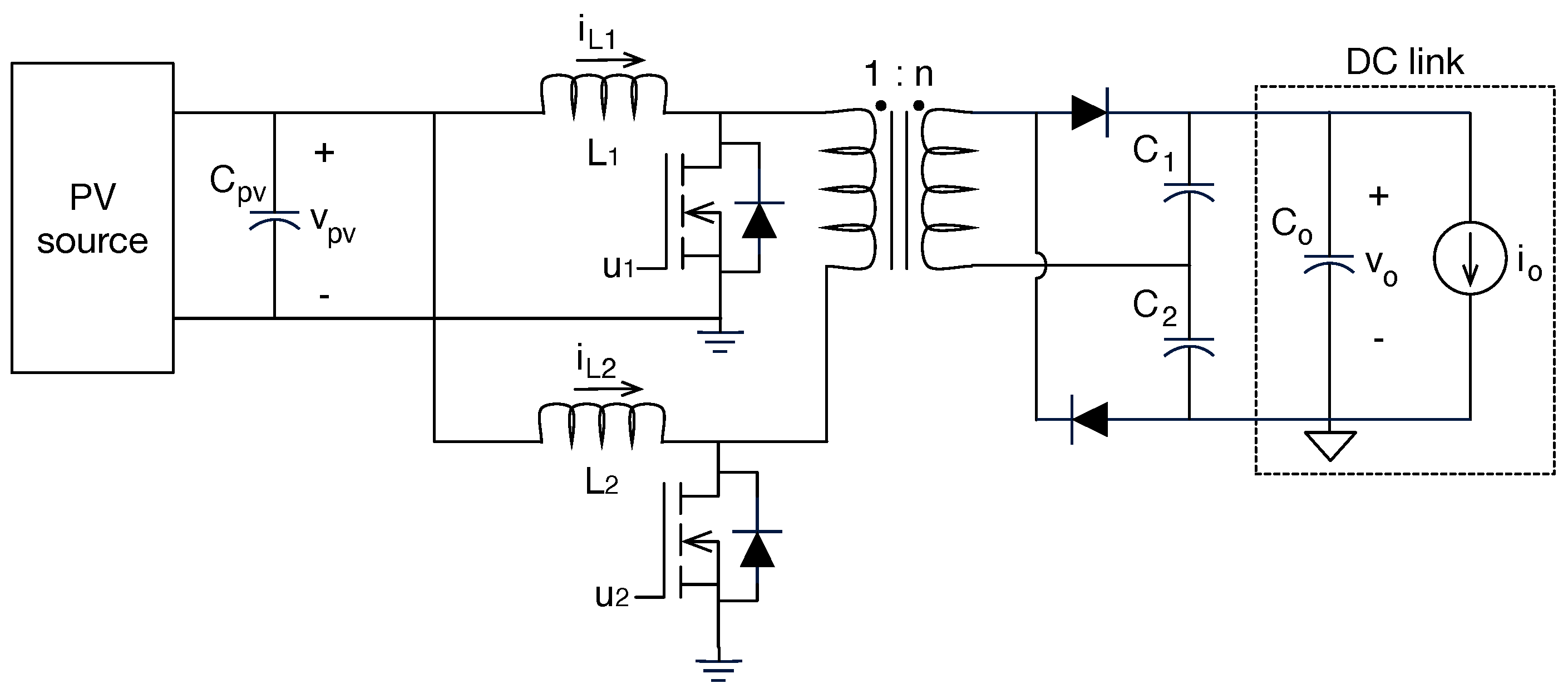
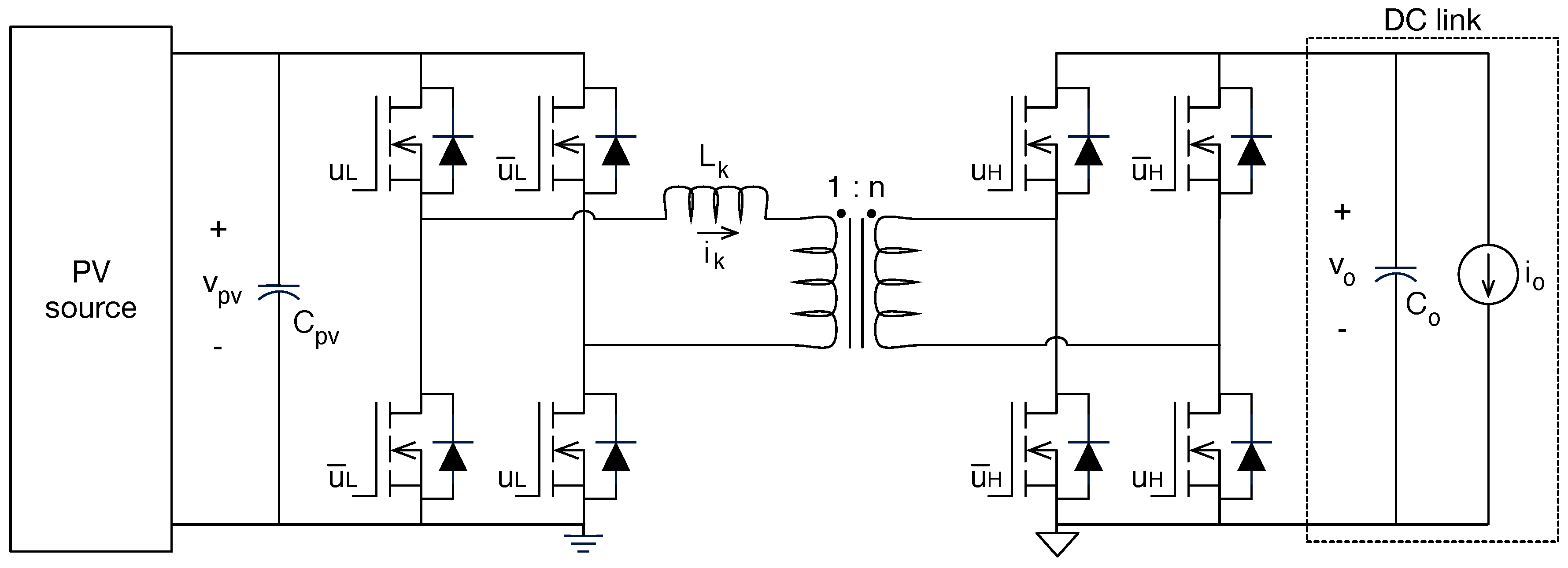
4.4.2. Buck-Boost and Flyback-Based DMPPT Units

The previous results show that the cross-coupling losses problem, at the PV side, can be avoided by using DMPPT units based on DC/DC converters with voltage-conversion ratios lower than one. Therefore, this subsection evaluates the same partial-shading conditions previously considered, but adopting buck-boost and flyback-based DMPPT units.
Assuming the same considerations made for the boost-based DMPPT unit, from the buck-boost circuit given in Figure 17, the steady-state inductor current given in (23) is calculated, which produces the power losses given in (24) and imposes the duty cycle given in (25) for a particular output voltage v o .
i L , b u c k / b o o s t = i p v d
P L , b u c k / b o o s t = i p v d 2 · R L
d b u c k / b o o s t = v o + v o 2 + 4 · R L · i p v · v p v + v o 2 · v p v + v o
Similarly, from the flyback circuit given in Figure 13, the following are obtained: the steady-state magnetizing current given in (26), the power losses given in (27), and the duty cycle given in (28).
i m , f l y b a c k = i p v d
P L , f l y b a c k = i p v d 2 · R L
d f l y b a c k = v o n + v o n 2 + 4 · R L · i p v · v p v + v o n 2 · v p v + v o n
To ensure a fair comparison, this new numerical analysis considers the same PV modules and lumped losses resistance R L used in the boost-based analysis, i.e., Table 11. From Equations (25) and (28), it can be seen that the duty cycle and power losses of the buck-boost-based DMPPT unit are equivalent to the flyback-based DMPPT unit with a unitary turn-ratio of the transformer ( n = 1 ). Moreover, the power losses in both DMPPT units is the same for n = 1 , while higher values of n produce a lower duty cycle, which also increases the power losses. Therefore, the numerical analysis for this subsection is performed using Equations (23)–(25).
The simulation of two buck-boost (flyback)-based DMPPT units connected in series, under the same partial-shading conditions of the previous simulations (1000 W/m2 and 400 W/m2), and with the same DC-link voltage (48 V), is performed in MATLAB (version 2024b) and reported in Figure 22. Since the PV modules have the same conditions considered in Figure 20, the output voltage of the second DMPPT unit for MPP operation ( v p v , 2 = 17.1 V) is v o , 2 = 13.7 V, which in this case is possible to reach with the buck-boost (flyback) converter. The top-left side of the figure confirms that the global MPP condition of the DMPPT system ( G M P P = 116.83 W) is reached; thus, the maximum power available in the PV sources is extracted. The top-right and bottom-right sides of the figure show the output voltages of both DMPPT units, which are in agreement with the theoretical values calculated with Equation (19), thus demonstrating the capability of buck-boost (flyback)-based DMPPT units to avoid cross-coupling losses. Finally, the bottom-left side of the figure confirms that the duty cycle of the second DMPPT unit is not saturated, which put into evidence its advantage over boost-based DMPPT units ( d 2 is saturated to zero in Figure 20).
Multiple simulations were carried out in MATLAB (version 2024b) for different DC-link voltages, and those results are reported in Figure 23. Figure 23a,c confirm that both DMPPT units operate at the MPP conditions for all DC-link voltages; thus, no cross-coupling losses are present in any value of the DC-link voltage. Figure 23b shows that the only losses affecting the DMPPT system performance are the converters’ losses, so no deviation from the MPP (at the PV sources side) occurs if the MPPT algorithms works correctly. Figure 23d shows that the output voltages are defined by the power balance; hence, voltage-conversion ratios lower than one are required for DMPPT 2, as observed in Figure 23e. However, due to the capability of the buck-boost (and flyback) converters to achieve those conditions, both DMPPT units achieve the required output voltages with the practical duty cycles reported in Figure 23f.
The results of the simulations reported in Figure 21 and Figure 23 show that the boost-based DMPPT systems can be affected by cross-coupling losses, while buck-boost (flyback)-based DMPPT systems do not have such a problem. However, at high DC-link voltages the boost-based DMPPT systems are not affected by cross-coupling conditions, so the converter selection must be carefully analyzed since boost-based DMMPT units have higher efficiency. The following subsection analyzes this topic with simulations of a large PV system.

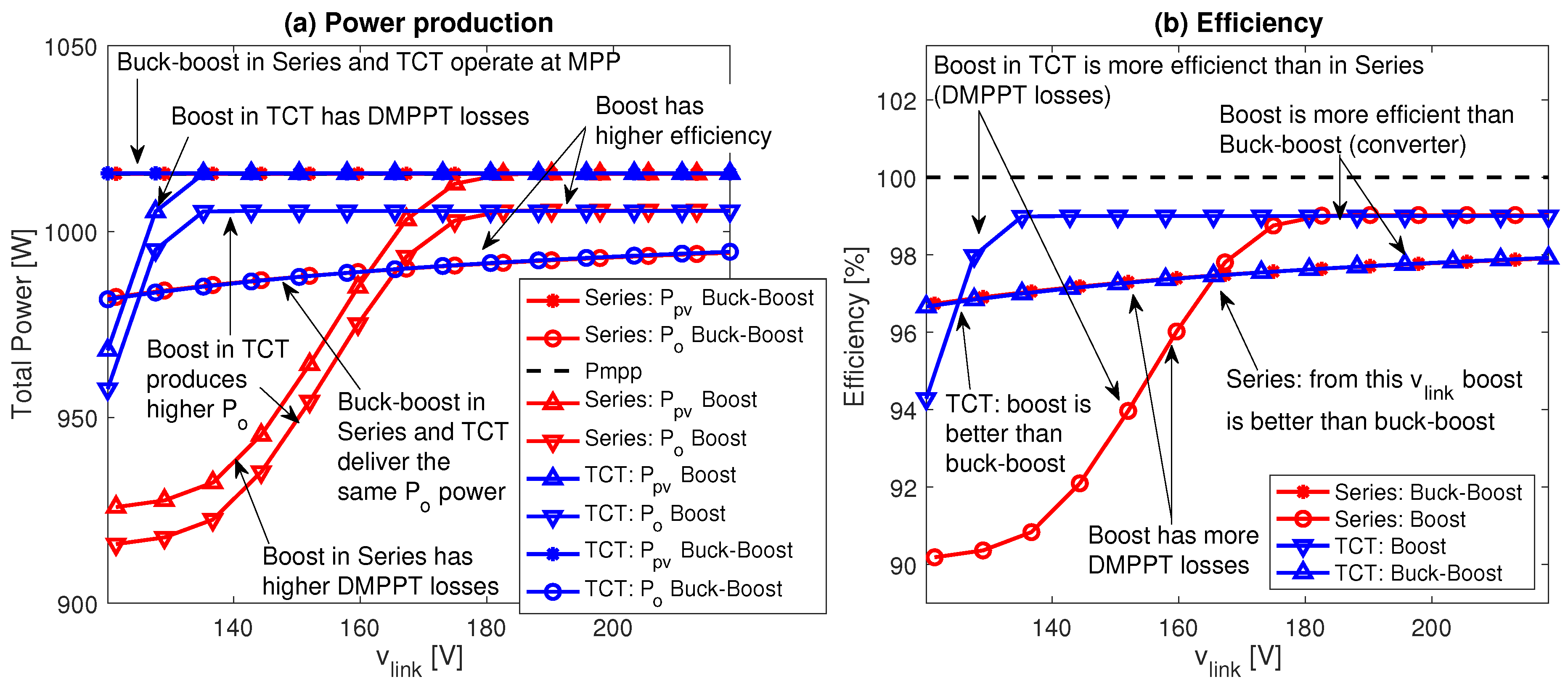
4.4.3. Comparison of Large DMPPT Systems with Series and TCT Connections

The cross-coupling losses for BIPV systems analyzed in refs. [31,34] only consider boost-based DMPPT units. In particular, the results reported in ref. [34] are focused on DMPPT systems with the TCT sub-type, while the results reported in ref. [31] are focused on the Series sub-type. Figure 24 shows the structure of large DMPPT systems with Series and TCT connections at the converter outputs. The main structure is formed by N series-connected DMPPT units, i.e., converters’ outputs connected in series, forming strings of DMPPT units. Then, M strings are connected in parallel to the DC-link, forming the DMPPT system. In the Series sub-type, the strings do not share any internal current; hence, those strings operate isolated from each other.
The TCT sub-type is obtained by connecting the negative terminals of all DMPPT units in a row, forming a grid, as depicted in Figure 24 (connections “TCT only”). Those new connections force the DMPPT units of a row to have the same output voltage, which also changes the DC-link voltage distribution between the rows. Equation (29) reports the DC-link voltage distribution in a ( N × M ) TCT-DMPPT system, where v o , k r o w is the output voltage imposed in the k-th row, which depends on the power balance between all the rows. The power P o , x r o w provided by the x-th row is the sum of the power delivered by the DMPPT units forming the row, which are connected in parallel. Therefore, changing a DMPPT system from Series sub-type to TCT sub-type also significantly changes the output voltages imposed on the converters, and the cross-coupling phenomenon could occur.
v o , k r o w = v l i n k · P o , k r o w j r o w = 1 N P o , j r o w where P o , x r o w = y = 1 M P o , x y
In order to provide a numerical comparison between both Series and TCT sub-types, the irradiance and shading profile reported in Table 5 are considered to carry out the MATLAB simulations for different DC-link voltages. The systems under test are formed by 18 DMPPT units ( N = 6 × M = 3 ) with both Series and TCT structures, and considering boost and buck-boost DMPPT units. Since the simulation of each DC-link condition requires 9 min, and 14 different DC-link voltages are evaluated for the boost and buck-boost DMPPT units in Series and TCT connections, the complete simulation requires 8 h and 24 min. Such a simulation time was significantly reduced by using the Parallel Toolbox (version 2024b) of MATLAB (version 2024b) running in a M4-Pro processor with 14 cores, requiring a final simulation time equal to 38 min and 20 s (13 times faster).
The results of this final simulation are presented in Figure 25, where the red traces report the performance of the Series sub-type, and the blue traces report the performance of the TCT sub-type. Figure 25a shows that Buck-boost DMPPT units are always able to reach the MPP conditions of the PV sources, thus no cross-coupling losses occur in series or TCT output connections. Similarly, the output power of the Buck-boost DMPPT units are almost the same in Series or TCT structures, hence the is no difference in selecting one sub-type or the another if Buck-boost (or flyback) DMPPT units are used.
Instead, the Boost DMPPT units have very different performance in Series and TCT sub-types: the series connection produces significant DMPPT losses (cross-coupling effect) for a large range of DC-link voltages ( v l i n k < 180 V), while the TCT connection only produces DMPPT losses for very low DC-link voltages ( v l i n k < 125 V). However, when the DMPPT losses are not present ( v l i n k > 180 V for Series and v l i n k > 125 V for TCT) the output power is the same.
It must be pointed out that both boost and buck-boost DMPPT units have the same lumped resistances, but the boost topology is more efficient due to the lower inductor current, this in comparison with the Buck-boost case. Such a condition is observed in the output powers of TCT and Series sub-types when the DMPPT losses are not present, since the DMPPT systems based on boost converters deliver higher power ( P o ) to the DC-link. However, when the DMPPT losses occur, the Buck-boost option could be more efficient: this is observed for DC-link voltages lower than 165 V in Series connection, where the boost-based system exhibit higher DMPPT losses, thus providing lower power ( P o ) to the DC-link in comparison with the buck-boost-based solution.
Figure 25b shows the output efficiency (output power/MPP power) of both Series and TCT sub-types with both converters. The results put into evidence that TCT-DMPPT systems based on boost converters have lower DMPPT losses in comparison with the Series sub-type (based on boost DMPPT units); however, TCT-DMPPT systems require a large number of DMPPT units, since at least two strings are needed. Therefore, small DMPPT systems are only configurable in Series sub-type. On the other hand, DMPPT systems based on buck-boost (or flyback) converters have the same efficiency, which is higher than boost-based systems with DMPPT losses, but lower than boost-based systems without DMPPT losses.
In conclusion, the selection of the DMPPT sub-type and converter must be based on particular analyses for each application, but the following general guidelines are applicable:
  • Series connection is unavoidable for small DMPPT systems if a boosting factor is needed.
  • For large DMPPT systems, the TCT connection is a viable option to be combined with boost converters.
  • For small DC-link voltages, it is better to adopt Series connection with buck-boost (or flyback) converters, since those topologies are not subjected to cross-coupling (DMPPT) losses.
  • Flyback DMPPT units are useful to introduce galvanic isolation, but increasing the turn-ratio of the transformer also reduces the system efficiency.

5. Conclusions

Building Integrated Photovoltaic (BIPV) systems is a key technology for developing Net Zero Energy Buildings (NZEBs) by integrating renewable generation directly into the architectural envelope. The comprehensive analysis carried out in this work has identified the critical factors that determine the energy efficiency of these systems.
The following fundamental technical recommendations for the optimal design of BIPV systems emerged from the systematic analysis reported in the paper:
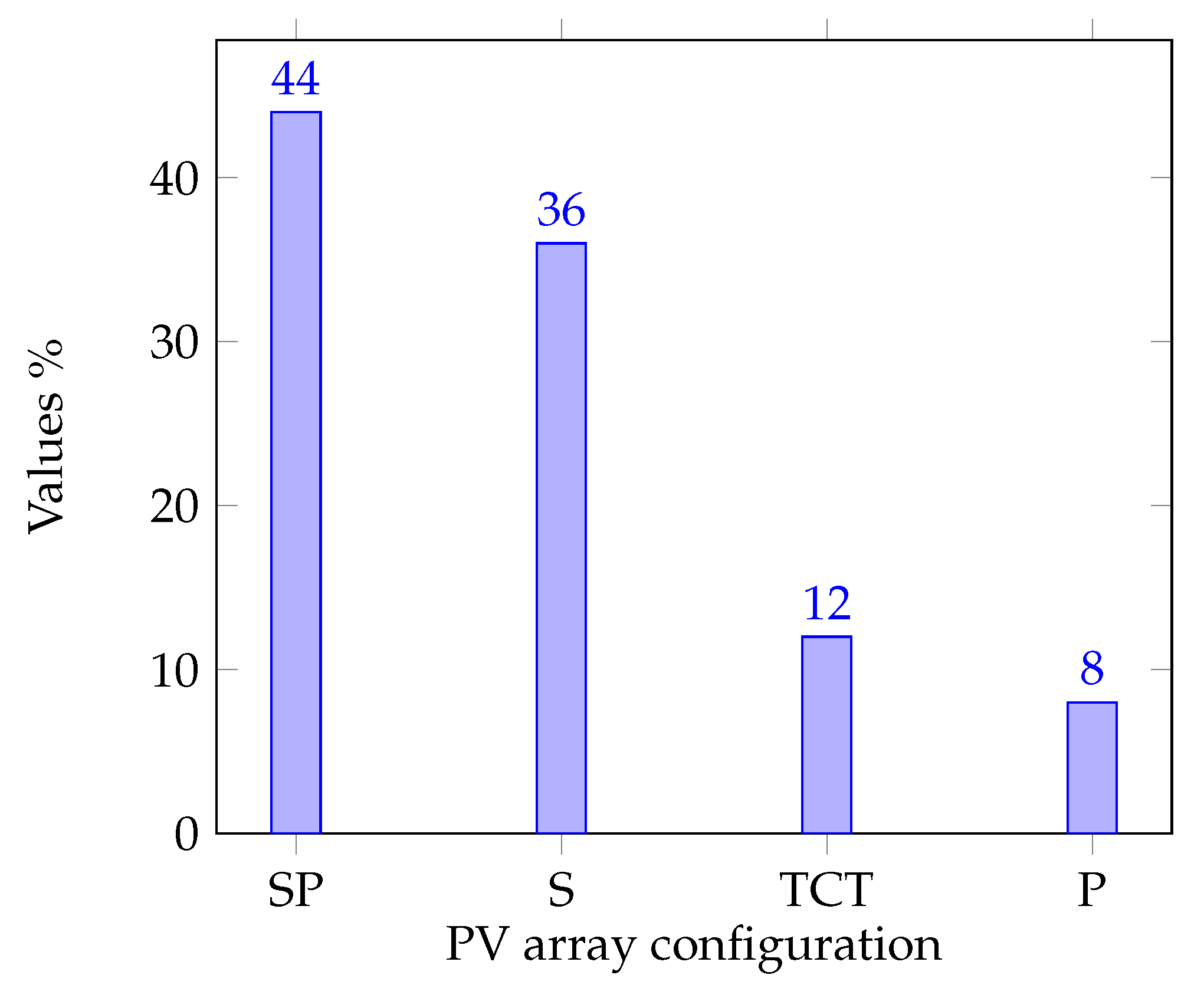
  • Mixed PV array configuration combines the advantages of series–parallel connections, improving resilience to partial shading.
  • MPPT algorithms should be selected considering their ability to handle both dynamic shading conditions and progressive degradation of the panels.
  • Distributed architecture (DMPPT) demonstrates superiority over centralized systems, particularly in urban environments with complex shading patterns.
  • Implementing a DC bus complementary to the conventional AC system optimizes energy efficiency by reducing conversion losses.
  • The panel’s electrical model selection (1 or 2 diodes) should correspond to the specific PV technology used in the architectural integration.
A relevant finding concerns cross-coupling in DMPPT systems with boost converters, whose mitigation, by changing the converter to, for example, a buck-boost, represents an opportunity to improve system efficiency further. The results presented provide a valuable framework for the development of future BIPV systems with higher efficiency that are better integrated into the sustainable built environment.
On the other hand, the rapid growth of the Electric Vehicle (EV) market presents a significant opportunity for future research focused on the integration of Vehicle-to-Grid (V2G) technology with Building Integrated Photovoltaic (BIPV) systems. This integration could optimize the use of renewable energy, improve grid stability, and reduce operating costs. In conclusion, the synergy between BIPV and V2G represents a promising field towards energy transition. Still, its success will depend on standardization, power electronics, and intelligent control advances. Future work must combine theoretical studies, technology development, and full-scale demonstrations to overcome these barriers.

Author Contributions

Conceptualization, all authors; methodology, all authors; software, C.A.R.-P.; validation, C.A.R.-P.; formal analysis, all authors; investigation, all authors; writing—original draft preparation, all authors; writing—review and editing, S.I.S.-G.; funding acquisition, C.A.R.-P. and L.A.T.-G. All authors have read and agreed to the published version of the manuscript.

Funding

This paper is part of the results of the research Project “Evaluación computacional de la factibilidad técnico-económica de la implementación de un sistema fotovoltaico integrado a edificios (BIPV) en el Instituto Tecnológico Metropolitano” code P24206 and Hermes code 62236, funded by Instituto Tecnológico Metropolitano and Universidad Nacional de Colombia.

Data Availability Statement

No new data were created or analyzed in this study.

Conflicts of Interest

The authors declare no conflicts of interest. The funders had no role in the design of the study; in the collection, analyses, or interpretation of data; in the writing of the manuscript; or in the decision to publish the results.

Abbreviations

The following abbreviations are used in this manuscript:
SDGSustainable Development Goals
NZEBNet Zero Energy Buildings
BIPVBuilding Integrated Photovoltaic
MPPMaximum Power Point
GMPPGlobal MPP
MPPTMPP Tracking
LMPPTLocal MPPT
DMPPTDistributed MPPT
CMPPTCentralized MPPT
ESSEnergy Storage Systems
PHESSPumped Hydro ESS
CAESSCompressed Air ESS
FESSFlywheel ESS
BESSBattery ESS
WWRWindow-to-Wall-Ratio
HVACHeating, Ventilation, and Air Conditioning
BSCBifacial Solar Cell
DPPDifferential Power Processing
DCDirect Current
ACAlternating Current
SSeries
PParallel
SPSeries–Parallel
TCTTotal-Cross-Tied
P&OPerturb and Observe
ICIncremental Conductance
AIArtificial Intelligence
PVPhotovoltaic
EVElectric Vehicle
V2GVehicle-to-Grid
WBGWide BandGap
ANFISAdaptive Neuro-Fuzzy Inference System
PIProportional Integral
FLCFuzzy Logic Controller
3SVSSThree-Stage Variable Step Size
2SVSSTwo-Stage Variable Step Size
DCLDouble Closed-Loop
CCMContinuous Conduction Mode
DCMDiscontinuous Conduction Mode
PSCPerovskite Solar Cell
S&HSample and Hold
BBSMBuck-Boost Single stage Microinverter
SWTScanning Window Technique
L-MLavenberg-Marquardt
FFFill Factor
ESAEstimation Solar Angle
DABDual Active Bridge
IIBCIsolated-Interleaved Boost Converter
RGAReserve Generation Algorithm
SMCSliding-Mode Controller

References

  1. Ross, J. (Ed.) The Sustainable Development Goals Report: Special Edition Towards a Rescue Plan for People and Planet; United Nations, Department of Economic and Social Affairs Statistics Division: New York, NY, USA, 2023. [Google Scholar]
  2. Ahmed, V.; Saboor, S.; Ahmed Alshamsi, H.; Ahmed Almarzooqi, F.; Abdalla Alketbi, M.; Ahmed Al Marei, F. Net-zero energy buildings and the sustainable development goals. In The Elgar Companion to the Built Environment and the Sustainable Development Goals; Opoku, A., Ed.; Edward Elgar Publishing: Cheltenham, UK, 2024; pp. 196–216. [Google Scholar] [CrossRef]
  3. Razzaq, I.; Amjad, M.; Qamar, A.; Asim, M.; Ishfaq, K.; Razzaq, A.; Mawra, K. Reduction in energy consumption and CO2 emissions by retrofitting an existing building to a net zero energy building for the implementation of SDGs 7 and 13. Front. Environ. Sci. 2023, 10, 1028793. [Google Scholar] [CrossRef]
  4. Scherz, M.; Passer, A.; Kreiner, H. Challenges in the achievement of a Net Zero Carbon Built Environment—A systemic approach to support the decision-aiding process in the design stage of buildings. IOP Conf. Ser. Earth Environ. Sci. 2020, 588, 032034. [Google Scholar] [CrossRef]
  5. Martín Chivelet, N.; Kapsis, C.; Frontini, F. (Eds.) Building-Integrated Photovoltaics: A Technical Guidebook; Routledge: New York, NY, USA, 2025. [Google Scholar]
  6. Awuku, S.A.; Bennadji, A.; Muhammad-Sukki, F.; Sellami, N. Myth or gold? The power of aesthetics in the adoption of building integrated photovoltaics (BIPVs). Energy Nexus 2021, 4, 100021. [Google Scholar] [CrossRef]
  7. Alshareef, R.S.; Maghrabie, H.M. Building-Integrated Photovoltaics with Energy Storage Systems—A Comprehensive Review. J. Energy Storage 2025, 116, 115916. [Google Scholar] [CrossRef]
  8. Chen, L.; Baghoolizadeh, M.; Basem, A.; Ali, S.H.; Ruhani, B.; Sultan, A.J.; Salahshour, S.; Alizadeh, A. A Comprehensive Review of a Building-Integrated Photovoltaic System (BIPV). Int. Commun. Heat Mass Transf. 2024, 159, 108056. [Google Scholar] [CrossRef]
  9. Belloni, E.; Bianchini, G.; Casini, M.; Faba, A.; Intravaia, M.; Laudani, A.; Lozito, G.M. An Overview on Building-Integrated Photovoltaics: Technological Solutions, Modeling, and Control. Energy Build. 2024, 324, 114867. [Google Scholar] [CrossRef]
  10. Constantinou, S.; Al-naemi, F.; Alrashidi, H.; Mallick, T.; Issa, W. A Review on Technological and Urban Sustainability Perspectives of Advanced Building-integrated Photovoltaics. Energy Sci. Eng. 2024, 12, 1265–1293. [Google Scholar] [CrossRef]
  11. Pelle, M.; Causone, F.; Maturi, L.; Moser, D. Opaque Coloured Building Integrated Photovoltaic (BIPV): A Review of Models and Simulation Frameworks for Performance Optimisation. Energies 2023, 16, 1991. [Google Scholar] [CrossRef]
  12. Martín-Chivelet, N.; Kapsis, K.; Wilson, H.R.; Delisle, V.; Yang, R.; Olivieri, L.; Polo, J.; Eisenlohr, J.; Ray, B.; Maturi, L.; et al. Building-Integrated Photovoltaic (BIPV) Products and Systems: A Review of Energy-Related Behavior. Energy Build. 2022, 262, 111998. [Google Scholar] [CrossRef]
  13. Kuhn, T.E.; Erban, C.; Heinrich, M.; Eisenlohr, J.; Ensslen, F.; Neuhaus, D.H. Review of Technological Design Options for Building Integrated Photovoltaics (BIPV). Energy Build. 2021, 231, 110381. [Google Scholar] [CrossRef]
  14. Abdullahi, M.M.; Mas’ud, A.A.; Mas’ud, I.A.; Ardila-Rey, J.A.; Muhammad-Sukki, F.; Karim, R.; Saudi, A.S.M.; Bani, N.A.; Wirba, A.V. A Review of Building Integrated Photovoltaic: Case Study of Tropical Climatic Regions. Int. J. Power Electron. Drive Syst. (IJPEDS) 2021, 12, 474. [Google Scholar] [CrossRef]
  15. Spiliotis, K.; Gonçalves, J.E.; Saelens, D.; Baert, K.; Driesen, J. Electrical System Architectures for Building-Integrated Photovoltaics: A Comparative Analysis Using a Modelling Framework in Modelica. Appl. Energy 2020, 261, 114247. [Google Scholar] [CrossRef]
  16. Ravyts, S.; Vecchia, M.D.; Broeck, G.V.D.; Driesen, J. Review on Building-Integrated Photovoltaics Electrical System Requirements and Module-Integrated Converter Recommendations. Energies 2020, 12, 1532. [Google Scholar] [CrossRef]
  17. Biyik, E.; Araz, M.; Hepbasli, A.; Shahrestani, M.; Yao, R.; Shao, L.; Essah, E.; Oliviera, A.C.; del Caño, T.; Rico, E.; et al. A Key Review of Building Integrated Photovoltaic (BIPV) Systems. Eng. Sci. Technol. Int. J. 2017, 20, 833–858. [Google Scholar] [CrossRef]
  18. Heinstein, P.; Ballif, C.; Perret-Aebi, L.-E. Building Integrated Photovoltaics (BIPV): Review, Potentials, Barriers and Myths. Green 2013, 3, 125–156. [Google Scholar] [CrossRef]
  19. Lee, K.H.; Song, Y.H. Analysis of Energy Reduction and Energy Self-Sufficiency Improvement Effects by Applying a Bidirectional Reflectance PV Array with Integrated External Shading at a School Building. Buildings 2023, 13, 2915. [Google Scholar] [CrossRef]
  20. Mehedi, I.; Salam, Z.; Ramli, M.; Chin, V.; Bassi, H.; Rawa, M.; Abdullah, M. Critical evaluation and review of partial shading mitigation methods for grid-connected PV system using hardware solutions: The module-level and array-level approaches. Renew. Sustain. Energy Rev. 2021, 146, 111138. [Google Scholar] [CrossRef]
  21. Al-Janahi, S.A.; Ellabban, O.; Al-Ghamdi, S.G. A Novel BIPV Reconfiguration Algorithm for Maximum Power Generation under Partial Shading. Energies 2020, 13, 4470. [Google Scholar] [CrossRef]
  22. Başoğlu, M.E. Analysis of The Performance Of The Distributed Maximum Power Point Tracking In Building Integrated Photovoltaic Systems. In Proceedings of the 2023 8th International Symposium on Electrical and Electronics Engineering (ISEEE), Galati, Romania, 26–28 October 2023; pp. 187–192. [Google Scholar] [CrossRef]
  23. Başoğlu, M.E. Comprehensive review on distributed maximum power point tracking: Submodule level and module level MPPT strategies. Sol. Energy 2022, 241, 85–108. [Google Scholar] [CrossRef]
  24. Kumar Yadav, V.; Yadav, R.; Singh, R.; Mishra, I.; Ganvir, I.; Manish. Reconfiguration of PV array through recursive addition approach for optimal power extraction under PSC. Energy Convers. Manag. 2023, 292, 117412. [Google Scholar] [CrossRef]
  25. Bonthagorla, P.K.; Mikkili, S. A Combined Adaptive Coefficient Particle Swarm Optimization MPPT approach and TT configured PV Array to Enhance Maximum Power under PSC. In Proceedings of the 2022 IEEE 1st Industrial Electronics Society Annual On-Line Conference (ONCON), Kharagpur, India, 9–11 December 2022; pp. 1–6. [Google Scholar] [CrossRef]
  26. Varma, G.H.K.; Barry, V.R.; Jain, R.K. A Total-Cross-Tied-Based Dynamic Photovoltaic Array Reconfiguration for Water Pumping System. IEEE Access 2022, 10, 4832–4843. [Google Scholar] [CrossRef]
  27. Appelbaum, J.; Aronescu, A.; Maor, T. Shading by Overhang PV Collectors. Appl. Sci. 2019, 9, 4280. [Google Scholar] [CrossRef]
  28. Yang, S.; Fiorito, F.; Sproul, A.; Prasad, D. Optimising Design Parameters of a Building-Integrated Photovoltaic Double-Skin Facade in Different Climate Zones in Australia. Buildings 2023, 13, 1096. [Google Scholar] [CrossRef]
  29. Olatunji, S.I.; Marzki, A.; Ng, A.; Ukeagbu, I.A. Perovskite PV MPPT Design for BIPV Application. In Proceedings of the 2023 IEEE 3rd International Conference in Power Engineering Applications (ICPEA), Putrajaya, Malaysia, 6–7 March 2023; pp. 323–327. [Google Scholar] [CrossRef]
  30. Zekorn, T.; Weihs, L.; Vohl, K.; Hanhart, M.; Rolff, L.; Wunderlich, R.; Heinen, S. Long Term Evaluation of a Pantile-based Maximum Power Point Tracking DC-DC Power Converter for Solar Roof Tiles. In Proceedings of the 2023 25th European Conference on Power Electronics and Applications (EPE’23 ECCE Europe), Aalborg, Denmark, 4–8 September 2023; pp. 1–8. [Google Scholar] [CrossRef]
  31. Pendem, S.R.; Mikkili, S. Assessment of Cross-coupling Effects in PV String-integrated-converters with P&O MPPT Algorithm Under Various Partial Shading Patterns. CSEE J. Power Energy Syst. 2022, 8, 1013–1028. [Google Scholar] [CrossRef]
  32. Sarkar, D.; Sahoo, R.K.; Kumar, A.; Sadhu, P.K. Comprehensive performance analysis of different MPPT algorithms for Building Integrated Photovoltaic system. In Proceedings of the 2021 IEEE Mysore Sub Section International Conference (MysuruCon), Hassan, India, 24–25 October 2021; pp. 1–6. [Google Scholar] [CrossRef]
  33. Mathew, D.; Farrag, M.E.; Naidu, R.C.; Muthu, R.K.; Sivaprakasam, A.; Somasundaram, P. Buck-Boost Single-Stage Microinverter for Building Integrated Photovoltaic Systems. Energies 2021, 14, 7854. [Google Scholar] [CrossRef]
  34. Pendem, S.R.; Mikkili, S.; Bonthagorla, P.K. PV Distributed-MPP Tracking: Total-Cross-Tied Configuration of String-Integrated-Converters to Extract the Maximum Power Under Various PSCs. IEEE Syst. J. 2020, 14, 1046–1057. [Google Scholar] [CrossRef]
  35. Wang, Y.H.; Liu, W.C.; Kuo, T.H. A 200W MPPT Boost Converter for BIPV Applications with Integrated Controller. In Proceedings of the 2014 International Symposium on Computer, Consumer and Control, Taichung, Taiwan, 10–12 June 2014; pp. 288–291. [Google Scholar] [CrossRef]
  36. Mazumdar, P.; Enjeti, P.N.; Balog, R.S. Analysis and Design of Smart PV Modules. IEEE J. Emerg. Sel. Top. Power Electron. 2014, 2, 451–459. [Google Scholar] [CrossRef]
  37. Elmakawi, A.; Bayındır, K. A High-Gain Non-Isolated Three-Port Converter for Building-Integrated PV Systems. Electronics 2022, 11, 387. [Google Scholar] [CrossRef]
  38. Kolhe, M.L.; Rasul, M. 3-Phase grid-connected building integrated photovoltaic system with reactive power control capability. Renew. Energy 2020, 154, 1065–1075. [Google Scholar] [CrossRef]
  39. Jois, S.; Bhosale, R.; Ramamritham, K.; Agarwal, V. Novel Scheme For Extracting Maximum Power From Façade Based Building Integrated Photovoltaics. In Proceedings of the 2019 IEEE 46th Photovoltaic Specialists Conference (PVSC), Chicago, IL, USA, 16–21 June 2019; pp. 2053–2059. [Google Scholar] [CrossRef]
  40. Demir, Y.C.; Aktacir, M.A. Experimental Investigation of the BIPV System under Şanlıurfa Meteorological Conditions. Appl. Sci. 2023, 13, 11286. [Google Scholar] [CrossRef]
  41. Pradhan, C.; Senapati, M.K.; Ntiakoh, N.K.; Calay, R.K. Roach Infestation Optimization MPPT Algorithm for Solar Photovoltaic System. Electronics 2022, 11, 927. [Google Scholar] [CrossRef]
  42. Liu, Y.; Liu, X.; Zhang, J.; Zhang, Y.; Zhu, Z. A Novel Maximum Power Point Tracking Control Strategy for the Building Integrated Photovoltaic System. Energies 2020, 13, 2679. [Google Scholar] [CrossRef]
  43. Sharma, P.; Duttagupta, S.P.; Agarwal, V. A Novel Approach for Maximum Power Tracking From Curved Thin-Film Solar Photovoltaic Arrays Under Changing Environmental Conditions. IEEE Trans. Ind. Appl. 2014, 50, 4142–4151. [Google Scholar] [CrossRef]
  44. Eum, J.; Park, S.; Choi, H.J. Effects of Power Optimizer Application in a Building-Integrated Photovoltaic System According to Shade Conditions. Buildings 2023, 14, 53. [Google Scholar] [CrossRef]
  45. Kalogerakis, C.; Koutroulis, E.; Lagoudakis, M.G. Global MPPT Based on Machine-Learning for PV Arrays Operating under Partial Shading Conditions. Appl. Sci. 2020, 10, 700. [Google Scholar] [CrossRef]
  46. Kumar T.M., S.; Sharma, S.; Kurian, C.P.; Varghese S., M.; George, A.M. Adaptive Neuro-fuzzy Control of Solar-Powered Building Integrated with Daylight-Artificial Light System. In Proceedings of the 2020 IEEE International Conference on Power Electronics, Smart Grid and Renewable Energy (PESGRE2020), Kerala, India, 2–4 January 2020; pp. 1–6. [Google Scholar] [CrossRef]
  47. Iam, I.W.; Ding, Z.; Huang, Z.; Lam, C.S.; Martins, R.P.; Mak, P.I. A Flexible Rooftop Photovoltaic-Inductive Wireless Power Transfer System for Low-Voltage DC Grid. IEEE Access 2023, 11, 51117–51132. [Google Scholar] [CrossRef]
  48. Kumari, P.; Kumar, N.; Panigrahi, B.K. A Framework of Reduced Sensor Rooftop SPV System Using Parabolic Curve Fitting MPPT Technology for Household Consumers. IEEE Trans. Consum. Electron. 2023, 69, 29–37. [Google Scholar] [CrossRef]
  49. Yadav, V.K.; Yadav, A.; Yadav, R.; Mittal, A.; Wazir, N.H.; Gupta, S.; Pachauri, R.K.; Ghosh, S. A novel reconfiguration technique for improvement of PV reliability. Renew. Energy 2022, 182, 508–520. [Google Scholar] [CrossRef]
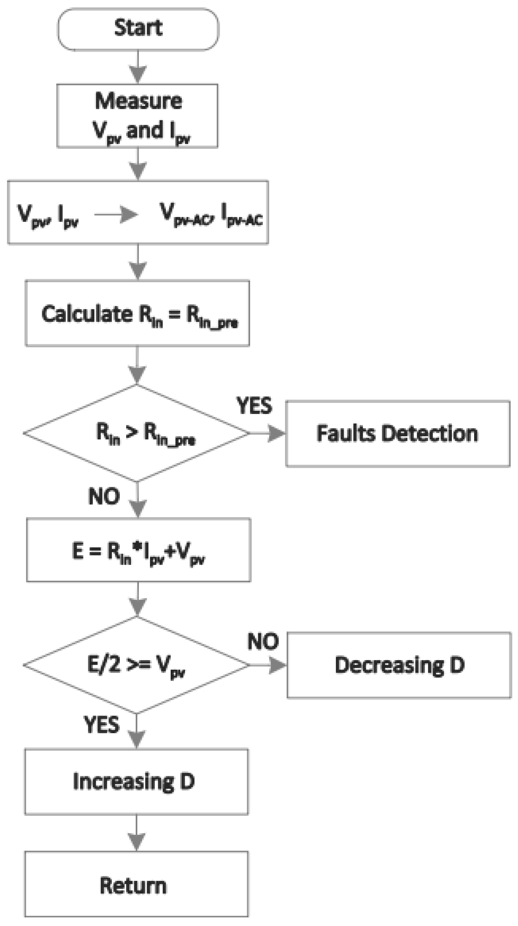
  50. Zheng, Z.; Nakajima, A.; Masukawa, S. A simple MPPT-Based Fault Detection Technique for a Photovoltaic Array System using Input Current and Voltage Ripples. In Proceedings of the 2021 24th International Conference on Electrical Machines and Systems (ICEMS), Gyeongju, Republic of Korea, 31 October–3 November 2021; pp. 309–313. [Google Scholar] [CrossRef]
  51. Chub, A.; Vinnikov, D.; Korkh, O.; Malinowski, M.; Kouro, S. Ultrawide Voltage Gain Range Microconverter for Integration of Silicon and Thin-Film Photovoltaic Modules in DC Microgrids. IEEE Trans. Power Electron. 2021, 36, 13763–13778. [Google Scholar] [CrossRef]
  52. Petrone, G.; Ramos-Paja, C.A.; Spagnuolo, G. Photovoltaic Sources Modeling, 1st ed.; Wiley: Hoboken, NJ, USA, 2017. [Google Scholar] [CrossRef]
  53. Al-Samawi, A.A.; Alkhafaji, A.S.; Atiyah, A.S.; Trabelsi, H. Review Mitigation Methods of Partial Shading Condition for PV System. In Proceedings of the 2024 21st International Multi-Conference on Systems, Signals & Devices (SSD), Erbil, Iraq, 22–25 April 2024; pp. 401–410. [Google Scholar] [CrossRef]
  54. Niazi, K.A.K.; Kerekes, T.; Dolara, A.; Yang, Y.; Leva, S. Performance Assessment of Mismatch Mitigation Methodologies Using Field Data in Solar Photovoltaic Systems. Electronics 2022, 11, 1938. [Google Scholar] [CrossRef]
  55. Alves, T.; N. Torres, J.P.; Marques Lameirinhas, R.A.; F. Fernandes, C.A. Different Techniques to Mitigate Partial Shading in Photovoltaic Panels. Energies 2021, 14, 3863. [Google Scholar] [CrossRef]
  56. Zeeshan, M.; Islam, N.U.; Faizullah, F.; Khalil, I.U.; Park, J. A Novel Row Index Mathematical Procedure for the Mitigation of PV Output Power Losses during Partial Shading Conditions. Symmetry 2023, 15, 768. [Google Scholar] [CrossRef]
  57. Osmani, K.; Haddad, A.; Jaber, H.; Lemenand, T.; Castanier, B.; Ramadan, M. Mitigating the effects of partial shading on PV system’s performance through PV array reconfiguration: A review. Therm. Sci. Eng. Prog. 2022, 31, 101280. [Google Scholar] [CrossRef]
  58. Yang, B.; Ye, H.; Wang, J.; Li, J.; Wu, S.; Li, Y.; Shu, H.; Ren, Y.; Ye, H. PV arrays reconfiguration for partial shading mitigation: Recent advances, challenges and perspectives. Energy Convers. Manag. 2021, 247, 114738. [Google Scholar] [CrossRef]
  59. Youssef, A.R.; Hefny, M.M.; Ali, A.I.M. Partial Shading Mitigation Approaches for PV Generation Systems: A Review. In Proceedings of the 2023 24th International Middle East Power System Conference (MEPCON), Mansoura, Egypt, 19–21 December 2023; pp. 1–6. [Google Scholar] [CrossRef]
  60. Belhachat, F.; Larbes, C. Photovoltaic Array Reconfiguration Strategies for Mitigating Partial Shading Effects: Recent Advances and Perspectives. Energy Convers. Manag. 2024, 313, 118547. [Google Scholar] [CrossRef]
  61. Santos De Araújo, J.V.; De Lucena, M.P.; Da Silva Netto, A.V.; Da Silva Vitorino Gomes, F.; De Oliveira, K.C.; De Souza Neto, J.M.R.; Cavalcante, S.L.; Valer Morales, L.R.; Villanueva, J.M.M.; Tavares De Macedo, E.C. Solar Tracking Control Algorithm Based on Artificial Intelligence Applied to Large-Scale Bifacial Photovoltaic Power Plants. Sensors 2024, 24, 3890. [Google Scholar] [CrossRef]
  62. Yan, H.W.; Liang, G.; Farivar, G.G.; Tafti, H.D.; Beniwal, N.; Pou, J. Enhanced Energy Storage Utilization Under Partial Shading Conditions in a Microgrid with Flexible Photovoltaic Power Control. In Proceedings of the 2024 International Conference on Electrical, Computer and Energy Technologies (ICECET), Sydney, Australia, 25–27 July 2024; IEEE: Piscataway, NJ, USA, 2024. [Google Scholar] [CrossRef]
  63. Rao, M.N.; Chaitanya, V.S.N.K. Experimental Analysis of Partial Shading on Solar Panels With Theuse of Aluminium Reflectors. In Proceedings of the 2020 IEEE International Conference on Advances and Developments in Electrical and Electronics Engineering (ICADEE), Coimbatore, India, 10–11 December 2020; IEEE: Piscataway, NJ, USA, 2020. [Google Scholar] [CrossRef]
  64. Mohamed Hariri, M.H.; Mat Desa, M.K.; Masri, S.; Mohd Zainuri, M.A.A. Grid-Connected PV Generation System—Components and Challenges: A Review. Energies 2020, 13, 4279. [Google Scholar] [CrossRef]
  65. Kabalcı, E. Review on novel single-phase grid-connected solar inverters: Circuits and control methods. Sol. Energy 2020, 198, 247–274. [Google Scholar] [CrossRef]
  66. Chub, A.; Korkh, O.; Kosenko, R.; Vinnikov, D. Novel Approach Immune to Partial Shading for Photovoltaic Energy Harvesting from Building Integrated PV (BIPV) Solar Roofs. In Proceedings of the 2018 20th European Conference on Power Electronics and Applications (EPE’18 ECCE Europe), Riga, Latvia, 17–21 September 2018; pp. P.1–P.10. [Google Scholar]
  67. Wang, X.; Wen, H.; Chu, G.; Zhou, J. Cost-effective and extensible LLC-resonant voltage-multiplier-based differential power processing optimizer for mismatched photovoltaic systems. Sol. Energy 2021, 225, 501–516. [Google Scholar] [CrossRef]
  68. Bastidas-Rodríguez, J.; Trejos-Grisales, A.; González-Montoya, D.; Ramos-Paja, C.A.; Petrone, G.; Spagnuolo, G. General modeling procedure for photovoltaic arrays. Electr. Power Syst. Res. 2018, 155, 67–79. [Google Scholar] [CrossRef]
  69. Gelani, H.E.; Dastgeer, F.; Nasir, M.; Khan, S.; Guerrero, J.M. AC vs. DC Distribution Efficiency: Are We on the Right Path? Energies 2021, 14, 4039. [Google Scholar] [CrossRef]
  70. Dastgeer, F.; Gelani, H.E. A Comparative analysis of system efficiency for AC and DC residential power distribution paradigms. Energy Build. 2017, 138, 648–654. [Google Scholar] [CrossRef]
  71. Starke, M.; Tolbert, L.M.; Ozpineci, B. AC vs. DC distribution: A loss comparison. In Proceedings of the 2008 IEEE/PES Transmission and Distribution Conference and Exposition, Chicago, IL, USA, 21–24 April 2008; pp. 1–7. [Google Scholar] [CrossRef]
  72. Hassan, S.J.U.; Mehdi, A.; Haider, Z.; Song, J.S.; Abraham, A.D.; Shin, G.S.; Kim, C.H. Towards medium voltage hybrid AC/DC distribution Systems: Architectural Topologies, planning and operation. Int. J. Electr. Power Energy Syst. 2024, 159, 110003. [Google Scholar] [CrossRef]
  73. Charadi, S.; Chaibi, Y.; Redouane, A.; Allouhi, A.; El Hasnaoui, A.; Mahmoudi, H. Efficiency and energy-loss analysis for hybrid AC/DC distribution systems and microgrids: A review. Int. Trans. Electr. Energy Syst. 2021, 31, e13203. [Google Scholar] [CrossRef]
  74. Alshammari, M.; Duffy, M. Bidirectional Synchronous H6 Inverter for Hybrid AC/DC Distribution System With Improved Light Load Efficiency. IEEE Access 2023, 11, 13138–13151. [Google Scholar] [CrossRef]
  75. Yang, L.; Peng, J.; Yang, F.; Zhang, Y.; Wu, H. Single-Phase High-Gain Bidirectional DC/AC Converter Based on High Step-up/Step-down DC/DC Converter and Dual-Input DC/AC Converter. In Proceedings of the 2019 IEEE 10th International Symposium on Power Electronics for Distributed Generation Systems (PEDG), Xi’an, China, 3–6 June 2019; IEEE: Piscataway, NJ, USA, 2019; pp. 554–559. [Google Scholar] [CrossRef]
  76. Mohamed, A.; Elshaer, M.; Mohammed, O. Bi-Directional AC-DC/DC-AC Converter for Power Sharing of Hybrid AC/DC Systems. In Proceedings of the 2011 IEEE Power and Energy Society General Meeting, San Diego, CA, USA, 24–29 July 2011; IEEE: Piscataway, NJ, USA, 2011; pp. 1–8. [Google Scholar] [CrossRef]
  77. Advantics. ADM-PC-BP25 User Manual. ADVANTICS Eurl. 2017. Available online: https://advantics.github.io/documentation/#/power-modules/ADM-PC-BP25/servicing (accessed on 10 January 2025).
  78. Ekici, E.; Koroglu, T.; Çelik, Ö. Design and Analysis of Two-Stage Bidirectional Power Converter for Vehicle-to-Grid Technology with Fuel Cell-Battery Electric Vehicle. J. Energy Storage 2025, 106, 114792. [Google Scholar] [CrossRef]
  79. Pouresmaeil, K.; Duarte, J.; Wijnands, K. Single-Phase Bidirectional ZVZCS AC-DC Converter for MV-Connected Ultra-Fast Chargers. In Proceedings of the PCIM Europe 2022; International Exhibition and Conference for Power Electronics, Intelligent Motion, Renewable Energy and Energy Management, Nuremberg, Germany, 10–12 May 2022; VDE Verlag GMBH: Berlin, Germany, 2022. [Google Scholar] [CrossRef]
  80. Peng, T.; Yang, P.; Dan, H.; Wang, H.; Han, H.; Yang, J.; Wang, H.; Dong, H.; Wheeler, P. A Single-Phase Bidirectional AC/DC Converter for V2G Applications. Energies 2017, 10, 881. [Google Scholar] [CrossRef]
  81. Robledo, C.B.; Oldenbroek, V.; Abbruzzese, F.; Van Wijk, A.J.M. Integrating a Hydrogen Fuel Cell Electric Vehicle with Vehicle-to-Grid Technology, Photovoltaic Power and a Residential Building. Appl. Energy 2018, 215, 615–629. [Google Scholar] [CrossRef]
  82. Chen, H.; Wang, X.; Khaligh, A. A Single Stage Integrated Bidirectional AC/DC and DC/DC Converter for Plug-in Hybrid Electric Vehicles. In Proceedings of the 2011 IEEE Vehicle Power and Propulsion Conference, Chicago, IL, USA, 6–9 September 2011; IEEE: Piscataway, NJ, USA, 2011; pp. 1–6. [Google Scholar] [CrossRef]
  83. Chin, V.J.; Salam, Z.; Ishaque, K. Cell modelling and model parameters estimation techniques for photovoltaic simulator application: A review. Appl. Energy 2015, 154, 500–519. [Google Scholar] [CrossRef]
  84. Valinejadshoubi, M.; Athienitis, A.K.; Bagchi, A.; Abtahi, M. Integrated Dynamic Photovoltaic Facade for Enhanced Building Comfort and Energy Efficiency. Biomimetics 2024, 9, 463. [Google Scholar] [CrossRef]
  85. Maghrabie, H.M.; Abdelkareem, M.A.; Al-Alami, A.H.; Ramadan, M.; Mushtaha, E.; Wilberforce, T.; Olabi, A.G. State-of-the-Art Technologies for Building-Integrated Photovoltaic Systems. Buildings 2021, 11, 383. [Google Scholar] [CrossRef]
  86. Olzhabay, Y.; Hamidi, M.N.; Ishak, D.; Marzuki, A.; Ng, A.; Ukaegbu, I.A. Performance Evaluation of Emerging Perovskite Photovoltaic Energy-Harvesting System for BIPV Applications. Smart Cities 2023, 6, 2430–2446. [Google Scholar] [CrossRef]
  87. Verma, P.; Kaur, T.; Kaur, R. Power control strategy of PV system for active power reserve under partial shading conditions. Int. J. Electr. Power Energy Syst. 2021, 130, 106951. [Google Scholar] [CrossRef]
  88. Hasan, M.M.; Jaman, S.; Geury, T.; Hegazy, O. Design and Simulation of a Grid-Connected Two-Stage Bidirectional Converter for a Combined PV-Stationary Energy Storage System. In Proceedings of the 2022 2nd International Conference on Sustainable Mobility Applications, Renewables and Technology (SMART), Cassino, Italy, 23–25 November 2022; pp. 1–8. [Google Scholar] [CrossRef]
  89. Hasan, M.M.; Jaman, S.; Geury, T.; Hegazy, O. Performance Assessment of a Grid-Connected Two-Stage Bidirectional Converter for a Combined PV–Battery Energy Storage System. Energies 2023, 16, 4486. [Google Scholar] [CrossRef]
  90. Sunddararaj, S.P.; Rangarajan, S.S.; Nallusamy, S.; Subramaniam, U.; Collins, E.R.; Senjyu, T. Design of Novel HG-SIQBC-Fed Multilevel Inverter for Standalone Microgrid Applications. Appl. Sci. 2022, 12, 9347. [Google Scholar] [CrossRef]
  91. Ismail, A.A.; Eldodor, M.; El-Deib, A.A. Development of a High Frequency Current Controlled Grid-connected Microinverter for PV Applications. In Proceedings of the 2022 23rd International Middle East Power Systems Conference (MEPCON), Cairo, Egypt, 13–15 December 2022; pp. 1–7. [Google Scholar] [CrossRef]
  92. Ravyts, S.; Vecchia, M.D.; Van den Broeck, G.; Driesen, J. Experimental Comparison of the Efficiency, Power Density and Thermal Performance of Two BIPV Converter Prototypes. In Proceedings of the 2018 IEEE 6th Workshop on Wide Bandgap Power Devices and Applications (WiPDA), Atlanta, GA, USA, 31 October–2 November 2018; pp. 7–13. [Google Scholar] [CrossRef]
  93. Jain, P.; Singh, J.P.; Kumar Panda, S. Fault remediation for distributed photovoltaic (PV) system. In Proceedings of the 2019 IEEE Applied Power Electronics Conference and Exposition (APEC), Anaheim, CA, USA, 17–21 March 2019; pp. 1057–1064. [Google Scholar] [CrossRef]
  94. Ravyts, S.; Van De Sande, W.; Vecchia, M.D.; Broeck, G.V.d.; Duraij, M.; Martinez, W.; Daenen, M.; Driesen, J. Practical Considerations for Designing Reliable DC/DC Converters, Applied to a BIPV Case. Energies 2020, 13, 834. [Google Scholar] [CrossRef]
  95. Ravyts, S.; Moschner, J.D.; Yordanov, G.H.; Van den Broeck, G.; Dalla Vecchia, M.; Manganiello, P.; Meuris, M.; Driesen, J. Impact of photovoltaic technology and feeder voltage level on the efficiency of façade building-integrated photovoltaic systems. Appl. Energy 2020, 269, 115039. [Google Scholar] [CrossRef]
  96. Fernández-Bustamante, P.; Calvo, I.; Villar, E.; Barambones, O. Centralized MPPT based on Sliding Mode Control and XBee 900 MHz for PV systems. Int. J. Electr. Power Energy Syst. 2023, 153, 109350. [Google Scholar] [CrossRef]
Figure 1. Photovoltaic array configurations used in BIPV systems.
Processes 13 01650 g001
Figure 2. Algorithms used for MPP tracking in photovoltaic systems.
Processes 13 01650 g002
Figure 3. CMPPT and DMPPT architectures.
Processes 13 01650 g003
Figure 4. Performance comparison of CMPPT and DMPPT systems under partial-shading conditions.
Processes 13 01650 g004
Figure 5. Block diagram of solution in ref. [46].
Processes 13 01650 g005
Figure 6. Control scheme of bidirectional converter in ref. [46].
Processes 13 01650 g006
Figure 7. MPPT structure proposed in ref. [32].
Processes 13 01650 g007
Figure 8. FLC structure proposed in ref. [32].
Processes 13 01650 g008
Figure 9. Flowchart of method proposed in ref. [32].
Processes 13 01650 g009
Figure 10. Flowchart of the solution proposed in ref. [50].
Processes 13 01650 g010
Figure 11. Cumulative number of papers regarding solutions for BIPV power systems.
Processes 13 01650 g011
Figure 12. Boost converter interfacing a PV source.
Processes 13 01650 g012
Figure 13. Flyback converter interfacing a PV source.
Processes 13 01650 g013
Figure 14. Interleaved boost converter (three branches) interfacing a PV source.
Processes 13 01650 g014
Figure 15. Isolated interleaved boost converter interfacing a PV source.
Processes 13 01650 g015
Figure 16. Dual-active bridge converter interfacing a PV source.
Processes 13 01650 g016
Figure 17. Non-inverting buck-boost converter interfacing a PV source.
Processes 13 01650 g017
Figure 18. Perturb and observe (left) and incremental conductance (right) algorithms.
Processes 13 01650 g018
Figure 19. DMPPT with series connection at the converters’ outputs (Series sub-type).
Processes 13 01650 g019
Figure 20. Feasible operation conditions for two boost-based DMPPT units under partial-shading (The GMPP condition is depicted as *).
Processes 13 01650 g020
Figure 21. Cross-coupling losses in two boost-based DMPPT units under partial-shading.
Processes 13 01650 g021
Figure 22. Feasible operation conditions for two buck-boost (flyback)-based DMPPT units under partial-shading (The GMPP condition is depicted as *).
Processes 13 01650 g022
Figure 23. No cross-coupling losses in two buck-boost (flyback)-based DMPPT units under partial-shading.
Processes 13 01650 g023
Figure 24. Large DMPPT system with series and TCT connections at the converters’ outputs (sub-types Series and TCT). Series: without the red connections. TCT: with the red connections.
Processes 13 01650 g024
Figure 25. Comparison of Series and TCT systems with Boost and Buck-boost DMPPT units.
Processes 13 01650 g025
Table 1. Electrical configurations for photovoltaic arrays.
Electrical ConnectionAdvantagesDisadvantages
Series (S) [15,19,20]Increases system voltage; simplifies inverter design.Failure of one panel significantly affects the others; panels with similar characteristics are required.
Parallel (P) [19]Failure or shading of one panel does not affect the others; more tolerant of panels with different electrical characteristics.Handles higher current levels than series; not useful for high voltage systems.
Mixed (SP) [13,15,19,20,21,22,23]Combines the advantages of S and P systems; voltage and current adjustment; high fault tolerance.More complex; requires balancing; can also be severely affected by partial shading.
Total-Cross-Tied (TCT) [19,20,21,24,25,26,27]High energy efficiency; increased robustness; adaptability.High complexity; high cost; high maintenance.
Table 2. Comparative summary of MPPT algorithms used in BIPV systems.
AlgorithmAdvantagesDisadvantages
P&O [22,28,29,30,31,32,33,34,35,36]Simple; low cost; quick response.Oscillations; sensitive to partial shading.
IC [26,32,37,38,39]High precision; less oscillations; better performance before partial shading.Complexity; higher cost; sensitivity to noise.
Optimization [25,27,40,41,42,43]High efficiency if partial shading is present; robustness; flexibility.Computational complexity; high cost; slow convergence.
AI [32,44,45,46]Adaptability; it is efficient with partial shading; high precision.Complexity; high cost; data dependence.
Hybrids [47,48,49,50,51]Improved efficiency; robustness; flexibility.Complexity; high cost; difficulty of adjustment.
Table 3. Partial shading mitigation strategies.
Partial Shading Mitigation TechniqueDescription
DMPPT [20,54,55]Energy production is optimized, which is achieved by installing a DC/DC converter and its MPPT algorithm in each module; there are conditions under which it may not be possible to find the MPP; complex solution since it requires more elements than the CMPPT architecture.
CMPPT [55]A single converter per string or substring and tries to optimize the power extraction of the entire panel group. It is generally less efficient than the system with DMPPT architecture.
Electrical configuration [55,56,57,58]Multiple strings in parallel or with intermediate connections reduce the impact of shading on the overall system performance.
Bypass diode [54,55]They are integrated into the solar panels, allowing the current to flow around the shaded cells. This avoids hot spots and improves performance, without completely eliminating losses.
Reconfiguration [20,56,57,58,59,60]Seeking to match the electrical characteristics of the arrangements, losses in partial shading conditions are reduced.
Solar tracking systems [61]Moving the panels to follow the trajectory of the sun throughout the day and reduce the angle of incidence minimizes shading caused by obstacles.
Storage systems [62]Storing excess energy and releasing it during partial shading helps minimize power fluctuations.
Reflectors [63]With fixed obstacles, the use of reflectors increases the irradiation on the panels.
Cleaning and maintenanceA periodic inspection to correct shading due to dirt, dust, and other obstacles can be very useful.
Table 4. Comparative summary of DMPPT and CMPPT architectures [20,34,36,37,39,64,65,66,67].
CharacteristicsDMPPTCMPPT
GranularityPanel or small group of panelsComplete Panel Array
ComplexityHigh—multiple convertersLow—single converter
CostHigh—more hardwareLow—less hardware
Efficiency in partial shadingHighLow
ScalabilityFlexibleLimited—requires redesign for expansion
Typical applicationsResidential, commercial, buildings, dynamic environmentsLarge solar plants, uniform conditions
Dynamic responseQuick—independent adjustment by panelSlow—centralized adjustment
Table 5. Irradiance/shading profiles: long shading patter entering the PV array [34].
String 1String 2String 3
Row 1800 W/m2800 W/m21000 W/m2
Row 2800 W/m2800 W/m21000 W/m2
Row 3500 W/m2500 W/m21000 W/m2
Row 4400 W/m2400 W/m21000 W/m2
Row 5300 W/m2300 W/m21000 W/m2
Row 6300 W/m2300 W/m21000 W/m2
Table 6. Characterization of DC and AC buses.
BusAdvantagesDisadvantages
DC [69,70,71]Transmission losses are lower than in an AC bus; simpler, less costs, less losses since the generation is DC.It is not easily integrated into existing facilities; it requires DC–AC conversion to feed traditional AC loads (more costs, more losses); it has no standards.
AC [69,71]Wide availability of equipment; compatible with available infrastructure; easy analysis of PF; supported by standards.Requires AC–DC conversion to feed DC loads (more complex, more costs, more losses); transmission losses are greater than those of the DC bus; requires synchronization with the grid.
Hybrid [72,73]Better cost-benefit ratio; system with the lowest losses because it has both buses.There are no standards; the control and analysis of the PF is more complex.
Table 7. Electrical model of PV panel classified by technology.
TechnologyElectric ModelEfficiencyCostTypical Applications
Monocrystalline silicon [83]1 or 2 diodes18–22%HighResidential, commercial, industrial
Polycrystalline silicon [83,84]1 or 2 diodes15–18%ModerateResidential, commercial
Thin-Film (a-Si) [40,42,84,85,86]1 diode6–10%LowBIPV, mobile devices
Thin-Film (CdTe) [84]1 diode10–12%LowLarge solar plants
Thin-Film (CIGS) [40,85,86]1 diode12–14%LowBIPV, mobile devices
Perovskita [9,86]1 diodeUp to 25%LowResearch, emerging applications
Table 8. Results from simulations in ref. [32].
MPPTIrradiance
(W/m2)
Maximum Power
from BIPV
(kW)
Maximum Power
Tracked by MPPT
(kW)
Efficiency
(%)
IC60016.215.8197.59
P&O15.9198.20
FLC15.9498.39
IC80021.720.9896.68
P&O21.0296.86
FLC21.1697.51
IC100026.8926.1597.26
P&O26.1897.37
FLC26.2597.63
Table 9. Summary of the works discussed.
Ref.MPPTConverterPV
Model
PV
Structure
IntegrationPartial
Shading
 [46]FLC
ANFIS
BoostNot givenNot givenRoofNot given
 [22]P&OBoostNot givenStringNot givenYes
 [32]P&O
IC
FLC
BoostDouble
diode model
Not givenFacadeNot given
 [29]P&OBoostNot givenCellFacadeNot given
 [33]P&OBuck-BoostOne
diode model
PanelNot givenNot given
 [42]3SVSSBoostOne
diode model
Not givenNot givenNo
 [43]P&OBoostNonlinear
regression
analysis
Not givenRoof curvedNot given
 [31]P&OBoostDouble
diode model
StringNot givenYes
 [50]Internal
impedance
BoostOne
diode model
ParallelFacadeNot given
 [86]P&OBoostOne
diode model
SPRoof
facade
No
Table 10. CMPPT and DMPPT solutions for BIPV installations.
Ref.TypeSub-TypeMPPT ConverterControllerMPPT Algorithm
[64]CMPPT-BoostN/AP&O
[65]CMPPT-Boost, DABN/AN/A
[87]CMPPT-BoostPI, voltageRGA
[37]CMPPT-BoostN/AIC
[88]CMPPT-BoostPI, voltageN/A
[89]CMPPT-BoostPI, voltageN/A
[90]CMPPT-BoostN/AN/A
[91]CMPPT-Flyback, boost-flybackN/AN/A
[92]CMPPT-Interleaved BoostN/AN/A
 [65]DMPPTMicroinverterBoost, FlybackN/AN/A
[36]DMPPTSeriesFlybackPI, cascade voltage-currentP&O
[34]DMPPTTCTBoostN/AP&O
[31]DMPPTSeriesBoostN/AP&O
[30]DMPPTString semi-DMPPTBoostPN/A
[29]DMPPTGeneralBoostN/AP&O
[66]DMPPTString semi-DMPPTFlyback, Quasi-Z sourceN/AVoltage sweep and LMPPT
[93]DMPPTSeriesNon-inverting buck-boostN/AN/A
[39]DMPPTParallelBoostN/AIC
[94]DMPPTGeneralIIBCN/AIC
[95]DMPPTParallelBoost, IIBCN/AN/A
[33]DMPPTMicroinverterBuck-boost inverterN/AP&O
[67]DMPPTDPPLLC inverterN/AP&O
[20]DMPPTSeries, Parallel, DPPBoost, FlybackN/AP&O
[42]DMPPTGeneralBoostPI, cascade voltage-current3-stage variable step
[96]DMPPTParallelBoostSMCPolynomial expressions
Table 11. Parameters adopted for the simulations.
STC Characteristic of the PV Module
ParameterValue
Short-circuit current i s c 5 A
Maximum power point voltage v m p p 18 V
Maximum power point current i m p p 4.72 A
Maximum power P m p p 85 W
Converter parameters
Parametervalue
Inductor 100 μ H, maximum current 10 A, series resistance of 40 m Ω (e.g., inductor PA4349.104ANLT, 100 μ H)
Semiconductors series resistances3.2 m Ω (e.g., MOSFET AOB290L)
Losses in the input/output connectors1 m Ω
Disclaimer/Publisher’s Note: The statements, opinions and data contained in all publications are solely those of the individual author(s) and contributor(s) and not of MDPI and/or the editor(s). MDPI and/or the editor(s) disclaim responsibility for any injury to people or property resulting from any ideas, methods, instructions or products referred to in the content.

