Article

Experimental Study on Thermal Performance of PCM in an Inclined Shell-and-Tube Latent Heat Thermal Energy Storage Unit

1
College of Architecture, Xi’an University of Architecture and Technology, Xi’an 710055, China
2
College of Mechanical Engineering, Xi’an University of Science and Technology, Xi’an 710054, China
*
Author to whom correspondence should be addressed.
Processes 2025, 13(5), 1557; https://doi.org/10.3390/pr13051557
Submission received: 15 April 2025 / Revised: 9 May 2025 / Accepted: 15 May 2025 / Published: 17 May 2025
(This article belongs to the Section Chemical Processes and Systems)

Abstract

Latent heat thermal energy storage systems play a crucial role in aligning energy supply with demand, enhancing the efficiency of energy usage, thereby aiding in energy conservation and emissions reduction, and promoting the efficient use of renewable energy. Therefore, we constructed an experimental apparatus for a shell-and-tube latent heat storage. This apparatus was utilized to investigate how varying the inclination angle of the heat storage device, the inlet temperature of the heat transfer fluid (HTF), and water flow direction affect both the heat transfer behavior and the thermal efficiency of the system. The findings indicate that as the inlet temperature rises, the melting rate of the phase-change material (PCM) increases; when the inclination angle is 0°, for every 5 °C increase in water temperature, the time required to reach thermal equilibrium is shortened by 2 h, and the time needed for the PCM to transition from a solid to a liquid state is correspondingly reduced by 2 h. Additionally, the temperature variation trend of the phase-change material remains fundamentally consistent at different inclination angles. However, as the angle increases from 0° to 90°, there is a gradual reduction in the melting rate. Whether the water enters from the top or bottom, the melting rate of the PCM remains almost unchanged, and the stabilized temperature of the PCM is also nearly the same.

1. Introduction

Conventional fossil fuel sources continue to be the dominant energy providers in the present day. Nonetheless, as the global economy and society advance swiftly, the need for energy is on the rise, resulting in a greater depletion of conventional fossil fuels. Although renewable energy sources like solar and wind power hold considerable promise, their variability and inconsistency hinder broad utilization. As a result, the creation of effective energy storage systems, especially thermal energy storage, becomes essential. Among the proposed solutions, latent heat storage employing a PCM offers distinct benefits. It reduces mismatches between energy supply and demand in both space and time due to its high energy storage capacity and capability to provide energy at nearly uniform temperatures. This technology demonstrates significant application potential in areas such as solar energy systems [1], energy savings in residential buildings [2], the food storage industry [3], and air conditioning systems [4], and has profound implications for achieving sustainable energy utilization and addressing climate change.
PCMs are a highly effective medium for thermal energy storage, offering several benefits. They can store and release substantial amounts of latent heat with minimal temperature fluctuations, which facilitates high energy density in thermal storage systems. Additionally, PCMs exhibit good reversibility and stability during multiple cycles of melting for heat storage and solidifying for heat release, offering broad application prospects in thermal management systems. However, PCMs also have certain limitations, such as poor thermal conductivity, which may result in low thermal energy transfer efficiency, Nevertheless, phase-change materials (PCMs) come with specific drawbacks, including limited thermal conductivity. This can lead to reduced efficiency in thermal energy transfer, ultimately impacting the system’s overall effectiveness. Additionally, the relatively high cost of PCMs restricts their widespread use in certain fields. To overcome these shortcomings, recent research has primarily focused on enhancing the thermal conductivity of PCMs through the incorporation of fillers with high thermal conductivity [5,6,7,8,9,10], including graphite and carbon nanotubes, and employing porous materials [10,11,12,13], such as metal foams. However, these methods also have certain drawbacks. For example, incorporating high-conductivity fillers might result in sedimentation or floating within the melted PCM, primarily because of the disparity in density between the fillers and the liquid phase-change material. Such issues may arise with prolonged usage, subsequently diminishing the system’s overall heat transfer efficiency. Additionally, the employment of porous materials, like metal foams, can reduce the effective volume available for PCMs due to the space they occupy, which ultimately decreases the energy storage capacity. Furthermore, the incorporation of fillers may also raise the preparation costs and complexity of a PCM, thereby reducing its feasibility in practical applications. By comparison, the design of appropriate heat exchangers [14] is a simple and practical approach to enhance heat transfer performance. This approach enhances the thermal energy transfer efficiency of a PCM while also mitigating problems associated with structural instability and the added costs of incorporating fillers, thus holding greater application potential in latent heat storage systems. Currently, latent heat storage systems employ two primary kinds of heat exchangers—direct contact and indirect contact types. Common types of indirect contact heat exchangers include plate, shell-and-tube, and packed-bed configurations, which can give rise to other more complex heat exchanger structures. Shell-and-tube heat exchangers have garnered significant attention in latent heat storage research because of their uncomplicated design, large capacity for phase-change materials per unit volume, ease of fabrication, and minimal thermal losses [15,16,17,18,19].
The shell-and-tube is designed with an annular configuration, where phase-change materials are situated within the gap between the concentric rings, allowing an HTF to circulate through the inner tube. Researchers have employed both experimental methods and simulation techniques to examine the thermal performance and heat transfer properties during the melting and freezing phases in shell-and-tube latent heat storage systems. Within these systems, a vertical shell-and-tube heat exchanger design is utilized to facilitate efficient thermal management. Trp [20] utilized both experimental and numerical simulations to explore vertical shell-and-tube heat exchangers within latent heat storage systems. The research concentrated on the transient convection phenomena observed during the phases of charging and discharging. The research demonstrated that the melting and freezing of phase-change paraffin occur as non-isothermal and isothermal phase transitions, respectively. It was determined that the interactions among the HTF, tube walls, and PCM need to be evaluated as an integrated system, which provides valuable insights for enhancing thermal performance and optimizing the design of latent heat storage units. In a related study, Jesumathy et al. [21] investigated the heat transfer behaviors of paraffin wax during melting and freezing in vertical annular energy storage systems. They concluded that paraffin is a highly effective PCM for latent heat storage. Their results showed that the Reynolds number had little effect on temperature distribution and heat transfer characteristics during both phases, with the heat transfer coefficient remaining constant throughout the freezing process. Furthermore, Akgun et al. [22] inclined the outer tube by 5 degrees while keeping the inner tube vertical. This modification led to a notable reduction in total melting time and enhanced heat transfer efficiency compared to the conventional cylindrical design. Furthermore, Longeon et al. [23] explored how natural convection influences the melting and solidification processes of paraffin through both experimental approaches and simulations. Their findings revealed that the device melted more rapidly when the heat transfer fluid was introduced from the top rather than from the bottom. Wang et al. [24] investigated the melting and freezing characteristics of erythritol within vertical shell-and-tube heat exchangers. Their findings indicated that the phase-change material (PCM) initially melts, occupying the upper section of the shell before progressing to the lower section. In contrast, the freezing process took place in the reverse order.
In latent heat storage systems featuring horizontal shell-and-tube heat exchangers, Jesumathy et al. [25] observed that in horizontal double-pipe thermal storage systems, natural convection mainly dictates the melting of paraffin, while conduction has a dominant effect during the freezing phase. Even small changes in the HTF inlet temperature can significantly impact the phase-change process: a 2 °C increase in inlet temperature boosts the rate of melting heat transfer by 25%, whereas a 2 °C decrease enhances the freezing heat transfer rate by 11%. Additionally, raising the HTF’s initial temperature from 70 °C to 74 °C leads to a 31% reduction in the total time required for paraffin to melt. Pahamli et al. [26] performed numerical simulations to examine the melting behavior of RT50PCM within double-tube latent heat storage systems. The results indicated that the downward shift in the inner tube led to a substantial reduction in melting time, achieving a maximum decrease of 64%. Mahdi et al. [27] discovered that when the phase-change material (PCM) is positioned in the inner tube, its melting time is reduced by approximately 50% compared to when it is located in the annular space. Additionally, raising the temperature of the heat transfer surface (HTS) can notably reduce the melting time. In contrast, during the freezing process, the PCM located in the annular space freezes more quickly, with the total freezing time being 43.4% shorter than when the PCM is positioned in the inner tube. Luo et al. [28] used the lattice Boltzmann method to simulate the melting process of PCMs in shell-and-tube heat exchangers. Their study revealed that increasing the number of heat transfer fluid (HTF) tubes significantly enhances the system’s thermal efficiency. Additionally, a centrally symmetrical tube configuration outperforms both linear and staggered arrangements in terms of thermal performance. Kousha et al. [29] carried out experiments to investigate the melting and freezing behaviors of RT35 PCMs in multi-tube heat exchangers. Research indicates that adding more inner tubes enhances the rates of PCM melting and solidification. For instance, when the HTF inlet temperature is set at 80 °C, the melting and freezing durations in a four-tube heat exchanger are reduced by 43% and 50%, respectively, compared to a single-tube configuration. As the quantity of inner tubes rises, it is likely that the average Nusselt number declines, possibly because the upper tubes hinder the flow of the PCM melt. The study also first proposed a correlation for calculating the Nusselt number in multi-tube thermal storage. In their study, Darzi et al. [30] employed numerical simulations to explore how PCMs behave during the melting process in both concentric and off-center horizontal cylindrical containers. Their findings indicated that during the initial phase of melting, heat conduction is the primary mechanism for heat transfer. A few minutes later, the upper section of the thermal cylinder experienced heat transfer mainly through natural convection, whereas the lower section predominantly relied on conduction. Furthermore, the rate of melting in the upper portion was considerably higher compared to that in the lower section. Additionally, when the inner tube shifted downwards, there was a noticeable increase in the melting rate of the PCM. Khillarkar et al. [31] conducted a numerical analysis to explore the melting behavior of a pure PCM using two different tube configurations. One design featured a square outer tube with a circular inner tube, whereas the other had a circular outer tube paired with a square inner tube. Their results demonstrated that natural convection leads to thermal stratification in the upper portion of the cavity.
In addition, numerous researchers have conducted in-depth studies on the latent heat energy storage characteristics of shell-and-tube heat exchangers under different tilt angles. Hasan [32,33] carried out experimental studies on a heat storage system. The results indicated that a horizontal configuration of the heat exchanger promotes faster phase transitions compared to a vertical setup. Seddegh et al. [34] performed a comparative study on the thermal efficiency of both horizontal and vertical shell-and-tube heat exchangers, incorporating the influence of gravity in their analysis. The results revealed that the horizontally oriented shell-and-tube heat exchanger exhibits superior performance over its vertical counterpart during the heat storage cycle. Kousha et al. [35] observed that as the angle of inclination in the shell-and-tube heat exchangers increased from 0° to 90°, the average temperature of the PCM decreased towards the end of the melting phase. Siyabi et al. [36] explored the melting behavior of PCMs in thermal storage systems at varying inclination angles. Their findings revealed that the inclination angle plays a crucial role in the melting process of PCM, with the highest melting rate occurring at a 45° angle, and the melting time being shorter compared to both 0° and 90°. Khobragade et al. [37] examined the influence of inclination angle on the thermal performance of a shell-and-tube heat exchanger using numerical simulations. Their results demonstrated that the horizontal configuration provided the most efficient thermal performance, achieving the highest melting fraction (98%) and maximum energy storage (231 kJ), while reaching steady-state conditions faster. As the inclination angle decreased, natural convection was enhanced, leading to notable improvements in both the melting fraction and energy storage capacity.
As mentioned above, previous research has primarily focused on shell-and-tube latent heat storage devices positioned either vertically or horizontally, with relatively little attention given to the effects of varying angles on the thermal behavior of these systems. Consequently, this study sets up an experimental platform to analyze how changes in the inclination angle affect the performance of shell-and-tube storage systems. Furthermore, it explores the influence of various factors, including the direction of water flow, alterations in the outer tube diameter, and variations in the inlet temperature of the heat transfer fluid, on the efficiency of the inclined shell-and-tube storage system. Through an in-depth analysis of these key parameters, this study not only reveals the phase change behavior patterns of PCM in shell-and-tube storage systems but also provides a scientific basis for optimizing the design of shell-and-tube latent heat storage systems and enhancing their overall thermal efficiency. This contributes important theoretical support for the further application of latent heat storage technology in the fields of renewable energy utilization and energy conservation.

2. Experimental System

2.1. Heat Storage Material

This research selected paraffin as the phase-change material for the latent heat energy storage system. The paraffin, provided by Shanghai Yijiu Chemical Co., Ltd. (Shanghai, China), with the model number 68 (the melting point varies within the range of 68 ± 2.5 °C). Paraffin, recognized as a highly effective phase-change material, offers excellent chemical stability, is non-toxic, and maintains its integrity without periodic degradation. This makes it an ideal candidate for efficient latent heat storage within a specific temperature range. The melting point refers to the temperature at which the PCM transitions from solid to liquid, while the melting enthalpy represents the amount of latent heat energy the material can store during this phase transition. Both of these factors are crucial in determining the overall performance of PCMs in energy storage applications. The melting point and the enthalpy of the fusion of paraffin were accurately measured using differential scanning calorimetry (DSC) technology, following the SH/T0589-94 [38] standard. The measured values were 66.3 °C and 199.2 kJ/kg, respectively. Figure 1 presents the specific results of the DSC analysis.

2.2. Experimental Apparatus

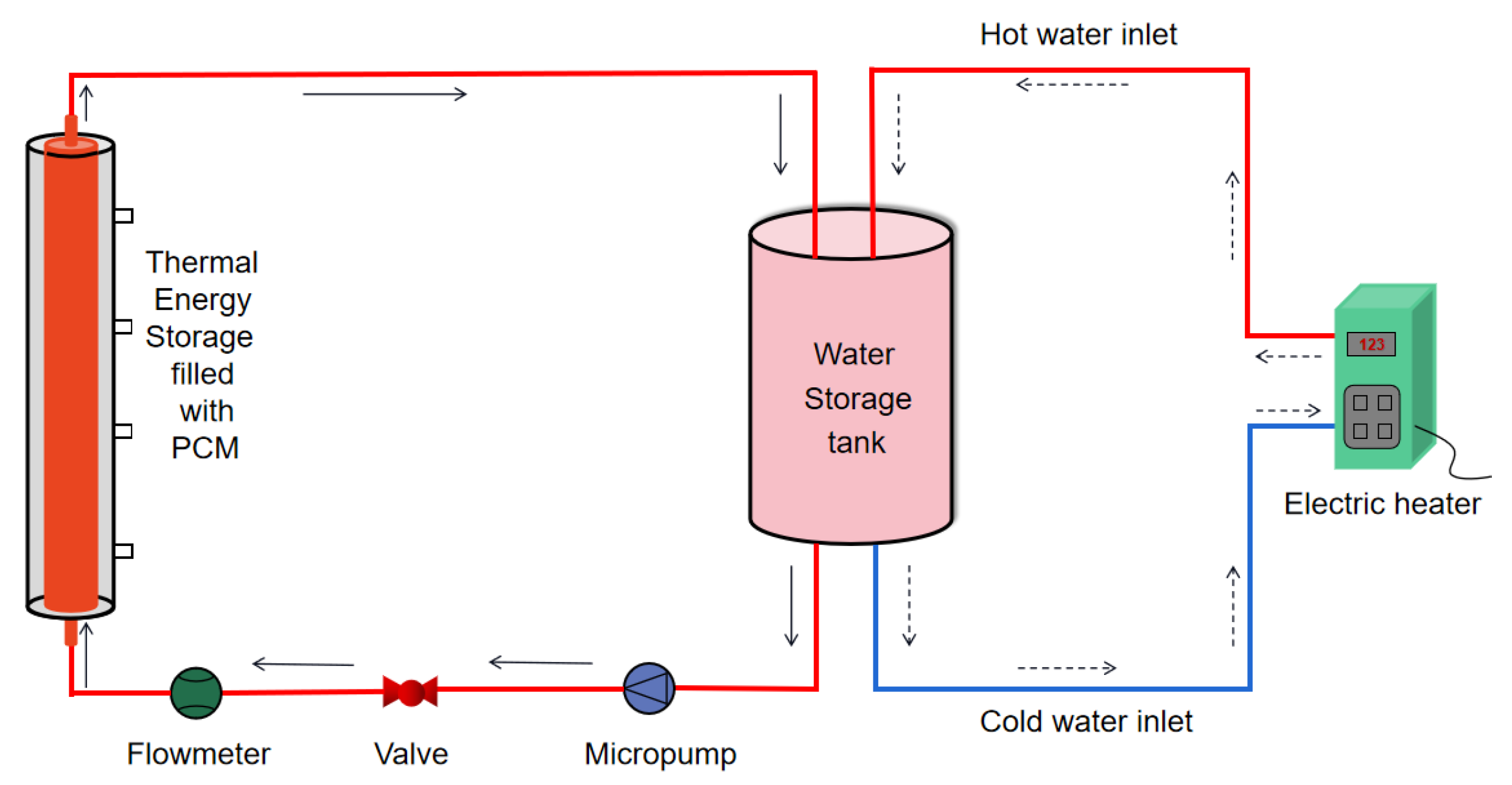
Figure 2 illustrates the schematic layout of the experimental system, which primarily consists of an electric heater(Valerias Fluid Technology (Guangzhou) Co., Ltd., Guangzhou, China), a water storage tank with insulated materials, a thermal energy storage module. The electric heater has been added in the text according to the requirements, while the two devices, a water storage tank with insulated materials and a thermal energy storage module, are custom-made by us, and a temperature recording and data acquisition system. There are two water flow loops in the present work. One is the water heating loop, where cold water is heated by the electric heater and then flows back to the hot water tank to a predetermined temperature and maintains a constant temperature. Water was supplied by a pump and flowed through an electric heater, then traveled to the water storage tank and remained at the preferred temperature for use. The alternative loop, referred to as the charging loop, enables some hot water to flow through the thermal energy storage module, facilitating heat transfer to the phase-change material (PCM) during the charging phase. Before the water enters the thermal energy storage module, both its flow rate and temperature are measured. The water flow rate was determined using a metal rotor flowmeter(Suzhou Jiayi Instrument Co., Ltd., Suzhou, China), this device features a measurement range of 100 to 1000 L/h and offers an accuracy of ±1.5%. Additionally, a T-type thermocouple was installed at the inlet of the thermal storage device, and another T-type thermocouple was placed at the outlet.
Three shell-and-tube latent heat storage devices with different outer diameters of the outer tube were designed and manufactured to investigate the thermal behavior of the phase-change material (paraffin). As shown in Figure 3, the outer diameters and thicknesses of the outer tubes in Figure 3a–c are Φ89 × 3 mm, Φ108 × 3 mm, and Φ127 × 3 mm, respectively, with a height of 800 mm for all. The inner tubes have the same outer diameter and thickness, both being Φ45 × 2.5 mm. The outer and inner tubes are arranged concentrically, with the material being 304 stainless steel. Paraffin fills the space between the inner and outer tubes, for heat storage. After being heated to transition from a solid to a liquid state, the phase change material is injected into this cavity. A heat transfer fluid circulates through the inner tube to facilitate heat exchange. To reduce heat loss to the environment, the outer tube is coated with a 30 mm thick layer of polyurethane foam for insulation.
This study utilizes type T thermocouples, which have a temperature range from −40 °C to +125 °C and an accuracy of ±0.5 °C. Each shell-and-tube latent heat storage system is fitted with 16 type T thermocouples to monitor the temperature distribution throughout the device. The thermocouples are integrated into the phase-change material (PCM) along both the axial and radial directions. The axial locations of the thermocouples within the PCM are designated as A (700 mm), B (500 mm), C (300 mm), and D (100 mm), with four thermocouples placed at each position, as depicted in Figure 3. The thermocouples at the radial positions are denoted as 1, 2, 3, and 4 (as shown in Figure 3), located in the annular space between the inner tube and the outer shell. In Figure 3a–c, the distances between two adjacent thermocouples in the radial direction are 5 mm, 8 mm, and 9 mm, respectively, while the distances from the thermocouple at position 1 to the inner tube are 2 mm, 3 mm, and 6 mm, respectively. The data acquisition system employs the Agilent 34901A data acquisition instrument to collect and record temperature data every 10 s.
A total of four series of comparative experiments were carried out, varying several parameters. These included different outer diameters for the shell-and-tube heat storage system (I, II, and III), various inlet temperatures for the heat transfer fluid (70, 75, and 80 °C), alternative flow directions for the water (with the inlet positioned at either the bottom or the top of the shell-and-tube heat storage unit), as well as distinct angles of inclination for the device (ranging from 0°, 30°, 45°, and 60°, to 90°). The angle of inclination is defined as the angle formed between the central axis of the shell-and-tube heat storage unit and the horizontal plane.

2.3. Uncertainty Analysis

The experimental setup consists of different components, each of which introduces some errors into the experimental results; therefore, uncertainty analysis of the experimental results has been conducted. When the measured temperature is between 0 °C and 100 °C, the accuracy of the T-type thermocouple is 0.5%, resulting in an accuracy error of ±0.5 °C. The estimated error caused by external factors is 1% (composed of changes in the experimental environment, deviations in the installation position of the thermocouple, and other factors), with an error of ±1 °C. The error of the temperature acquisition device is 0.075%, thus the error value is ±0.075 °C. The root-sum-square method (Moffat [39]) is used to calculate the temperature measurement error, and the calculation formula is as follows:
E T = ± E B 2 + E C 2 + E T h 2
where E T is the temperature measurement error, E B is the measurement error of the data acquisition card, E C is the errors caused by external factors, and E T h is the thermocouple error. It can be obtained through calculations that E T = 1.1   .
The flow rate error of water can be calculated as 0.045 L/min based on the accuracy of the thermal mass flowmeter and the errors during calibration.

3. Experimental Results

The heat transfer efficiency of the PCM under thermostatic water flow was measured by comparing different variables. Prior to the formal experiment, a preliminary investigation was conducted utilizing an inlet temperature of 75 °C and a flow rate of 9 L/min, tube I, an inclination angle of 45°, and the water entering from the bottom. The temperature charts of four cross-sectional areas A, B, C, and D under the proposed conditions were compared (Figure 4). Since the temperature variation trends of the four cross-sections were in good agreement, point C2 was taken as the experimental point for subsequent experimental research.

3.1. Effect of Outer Tube Diameter

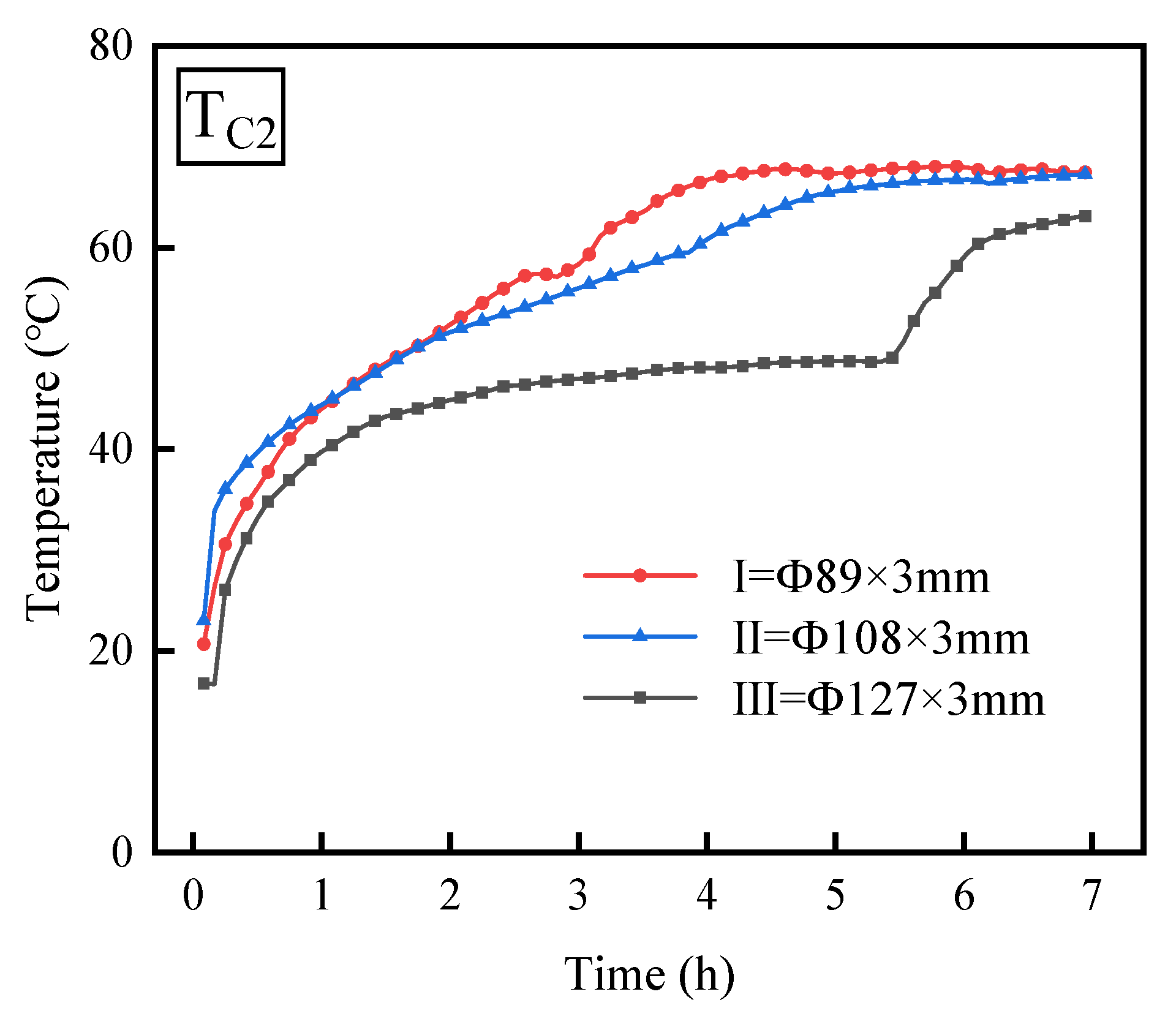
Figure 5 illustrates the effect of three different outer tube diameters (I, II, and III) on the melting rate of PCM in a shell-and-tube thermal storage device under conditions of a 45° inclination angle and an inlet water temperature of 75 °C, with water flowing in from the bottom and leaving from the top. The figure reveals that, over time, the temperature variations in the PCM in the thermal storage devices using outer tubes I and II are largely consistent, initially rising sharply and then increasing slowly until reaching thermal equilibrium. However, with the use of outer tube III, the temperature change in the PCM differs from that of outer tubes I and II, rising sharply at first, then slightly increasing, followed by a rapid rise before ultimately reaching thermal equilibrium. The figure also shows that when utilizing outer tube type I, the PCM experiences a substantial rise in temperature during the initial hour of the experiment. This rapid increase occurs because the temperature difference between the PCM and the water is considerable, leading to a significant absorption of sensible heat by the PCM. As time progresses, from 1 h to 4.5 h, the rate of temperature increase in the PCM gradually slows down due to the fact that the temperature of the PCM near the inner tube reaches its melting point and begins to absorb latent heat. However, there is still solid-phase thermal conduction between the PCMs. At the bottom of the shell-and-tube thermal storage device, the paraffin melts, while the paraffin at the top remains solid. Due to the difference in density, the solid paraffin at the top slides down to the bottom, resulting in a slower temperature increase at measurement point C2. After 4.5 h of the experiment, the temperature of the PCM remained at approximately 68 °C without further change, indicating that the PCM had essentially completed the melting process. Similarly, when the outer tube was of type II, in the first hour of the experiment, the temperature of the PCM rapidly increased. From the first hour to 5.5 h, the temperature of the PCM increased linearly, and after 5.5 h, it stabilized at approximately 67 °C without further change. When the outer tube was of type III, during the first 1.5 h of the experiment, the PCM absorbed sensible heat, causing the temperature to rise rapidly. Subsequently, between 1.5 h and 5.3 h, the temperature slightly increased due to the large annular space containing the PCM, which caused the solid paraffin on the upper side of the shell to slide to the bottom, as well as the PCM absorbing a significant amount of latent heat, resulting in a slight increase in the temperature at measurement point C2. At 5.3 h, the temperature rose sharply again and eventually stabilized because the PCM near measurement point C2 had essentially completed melting, and the PCM absorbed sensible heat, leading to a rapid increase in temperature. Additionally, by comparing the time required for the PCM to reach stability, it can be observed that as the diameter of the outer tube increases, the melting rate of the PCM gradually decreases.

3.2. Effect of Inclination Angle

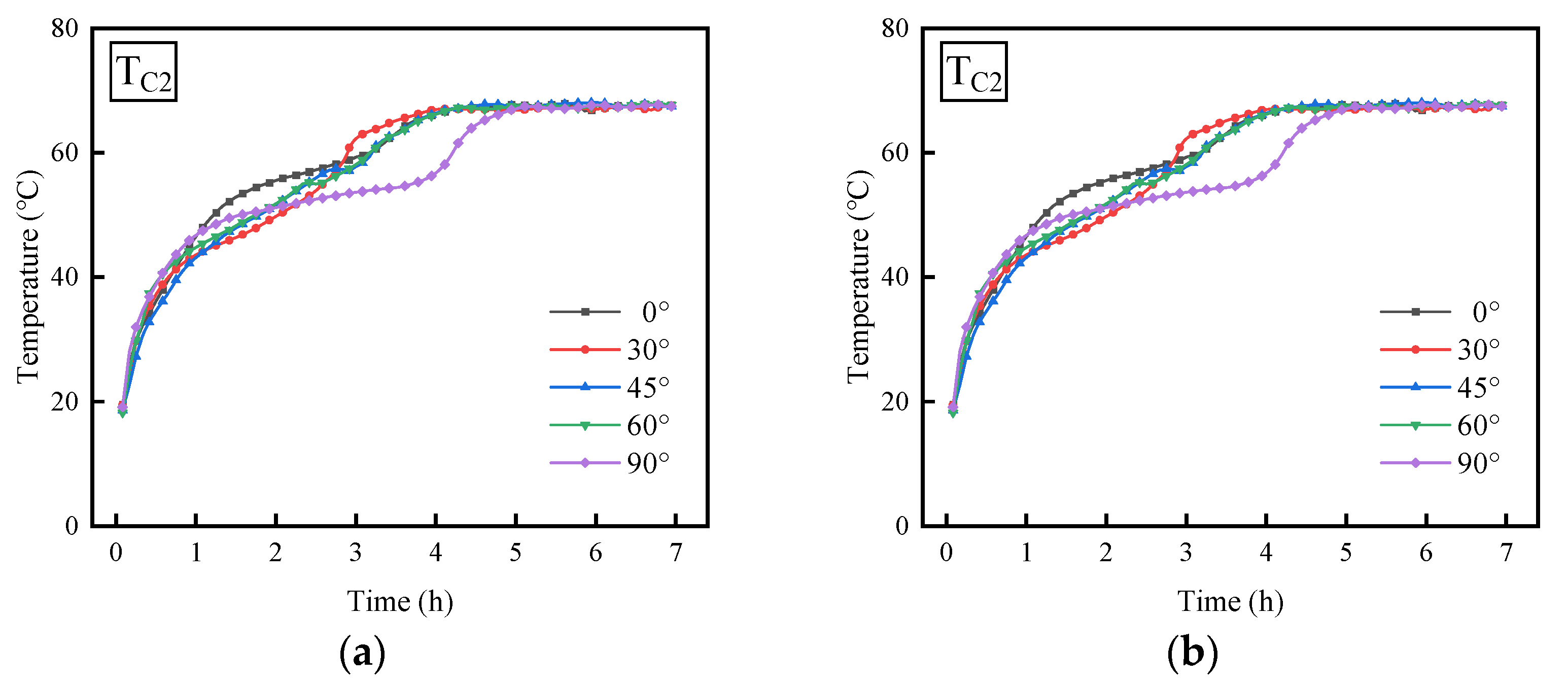
Figure 6a shows the effect of different inclined angles on the temperature variation in PCM within tube I of a shell-and-tube thermal storage system, with the water inlet temperature set to 75 °C, and with water flowing in from the bottom while exiting from the top. The figure reveals that, as time progresses, the temperature variation patterns of the PCM across different inclination angles show a generally similar trend. In the initial phase, the temperature rises sharply, followed by a relatively mild growth phase, and ultimately accelerates again until thermal equilibrium is reached. However, the temperature change patterns at different inclined angles exhibit significant temporal differences; with the inclination angle rising from 0° to 90°, the time needed for the PCM to reach equilibrium becomes longer, and the melting rate decreases. For example, during the first hour, the PCM temperatures at all five inclined angles rise sharply, during which the PCM absorbs a considerable amount of sensible heat. As time progresses, the temperature near the inner tube reaches the melting point of the PCM, initiating the melting process. The melting region is more uniformly distributed around the inner tube at an inclination angle of 0°, with a faster melting rate, resulting in the temperature at measurement point C2 being higher than at other angles during 1 to 3 h. However, as natural convection takes effect, once the solid PCM in the upper section has largely melted, the temperature gap between the molten PCM lessens, leading to reduced natural convection intensity. Consequently, the melting rate slows down during 3 to 4 h, and the temperature increase in the PCM decelerates, ultimately reaching thermal equilibrium after 4 h. In contrast, at an inclination angle of 90°, the melting rate accelerates between 3.5 and 5 h, causing the PCM temperature to rise rapidly, reaching thermal equilibrium after 5 h. This is because, at an inclination angle of 90°, the vertical circulation formed maintains its intensity throughout the process, thus accelerating the melting rate in the later stages and causing a rapid temperature increase [35]. By comparison, at inclination angles of 30°, 45°, and 60°, the PCM temperatures during the initial half of the melting process are lower than those at an inclination angle of 0°. Conversely, in the latter half of the melting process, the situation is reversed. Additionally, the times for the PCM to reach thermal equilibrium are 4.2 h, 4.5 h, and 4.6 h, respectively. To further validate this result, we increased the water temperature to 80 °C and tested the temperature variations in the phase change material (PCM) under conditions of 0°, 45°, and 90° inclination angles. As shown in Figure 6b, the same conclusions were drawn.

3.3. Effect of Inlet Temperature

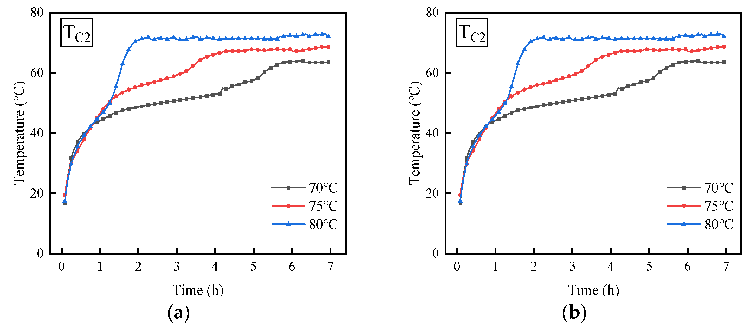
Figure 7a shows the effect of different water temperatures on the temperature of the PCM inside the tube when type I pipes are used and the inclination angle is 0°, with water flowing from the inlet to the outlet. The figure illustrates that as the water temperature rises from 70 °C to 80 °C, the duration needed for the PCM to achieve thermal equilibrium steadily decreases. This trend indirectly suggests that the melting rate of the PCM is increasing. For instance, when the water temperature is 80 °C, the temperature of the PCM rapidly rises to 40 °C within one hour before the experiment, and then consistently increases at a similar rate within 1 to 2 h, reaching 72 °C after the second hour. In the case of a water temperature of 75 °C, the PCM melts at the same rate during the first 2 h, but the melting rate gradually slows down thereafter; however, after 3 to 4 h, the melting rate accelerates again, ultimately reaching a thermal equilibrium of 65 °C after 4 h. For the scenario with a water temperature of 70 °C, the melting rate of the PCM is significantly lower than that at 75 °C and 80 °C, achieving a thermal equilibrium temperature of 60 °C after 6 h. Studies suggest that a larger temperature gap between the constant temperature water and the PCM results in better heat transfer efficiency, which in turn enhances the melting rate of the PCM. Moreover, by comparing the times required for the PCM to reach thermal equilibrium, it can be noted that for every 5 °C increase in water temperature, the time needed to achieve thermal equilibrium decreases by 2 h, and the time for the PCM to transition from solid to liquid state also correspondingly shortens by 2 h. To enhance the verification of the experimental results, the inclination angle of the shell-and-tube thermal storage device was varied from 0° to 45°, while ensuring that other conditions remained unchanged. As shown in Figure 7b, the conclusions remain consistent, though there are significant temporal differences in the temperature change patterns at different inclination angles.

3.4. Effect of Water Flow Direction

Figure 8a illustrates the effect of different water flow directions on the temperature of the PCM in a shell-and-tube thermal energy storage system. The system operates with a water temperature of 75 °C, a Type I tube as the outer tube, and an inclination angle of 45°. The temperature variation trends of the PCM under the two different water flow directions are fundamentally consistent, showing a rapid increase followed by a slower increase, and ultimately stabilizing. Additionally, the figure indicates that during the interval of 0 to 1.5 h, the PCM temperatures and melting rates under both water flow directions are identical, while after 3 h, the PCM temperature at the top inlet is slightly higher than that at the bottom inlet. To further validate this conclusion, with other conditions unchanged, the inclination angle of the shell-and-tube thermal energy storage system was adjusted from 45° to 90°, as shown in Figure 8b. Overall, the temperature variation trends of the PCM under both water flow directions remain fundamentally the same, and throughout the thermal energy storage process, the PCM temperature at the top inlet is consistently slightly higher than that at the bottom inlet. Both experiments yielded the same conclusion, indicating that regardless of whether the inlet is at the top or bottom, the impact on PCM melting is minimal.

4. Conclusions

This research conducts experimental investigations into how various outer tube diameters, different angles of inclination, inlet temperatures of diverse heat transfer fluids, and water flow directions affect the shell-and-tube latent heat storage system. The conclusions derived from this research can be summarized as follows:
(1)
When the outer diameters of the thermal energy storage device are 89 mm and 108 mm, the temperature variation trends of the PCM are basically consistent. However, when the outer diameter is 127 mm, the temperature fluctuation pattern of the PCM differs during the middle phase compared to the other two diameters. Furthermore, as the diameter of the outer tube increases, the time required for the PCM temperature to reach stability also lengthens, while the PCM’s melting rate steadily declines.
(2)
The temperature variation trends of the PCM are fundamentally consistent under different inclination angles, characterized by a sharp increase in the initial phase, followed by a relatively gentle growth phase, and finally accelerating again until thermal equilibrium is achieved. As the angle of inclination for the thermal energy storage device rises from 0° to 90°, the duration necessary for the PCM to achieve equilibrium is extended, while simultaneously, the melting rate of the PCM experiences a reduction.
(3)
When the temperature of the water rises from 70 °C to 80 °C, the time needed for the PCM to stabilize diminishes, suggesting an increase in the melting rate of the PCM. Moreover, when the inclination angle of the shell-and-tube thermal energy storage device is 0°, for every 5 °C increase in water temperature, the time required to reach thermal equilibrium is shortened by 2 h.
(4)
Under the same water temperature and inclination conditions, the PCM temperatures are basically consistent whether the inlet is at the top or bottom, and the melting rates of the PCM are largely the same.

Author Contributions

Conceptualization, K.F., S.Z., H.G. and Z.D.; methodology, K.F. and H.G.; formal analysis, K.F., S.Z. and H.G.; investigation, K.F.; data curation, K.F., S.Z. and H.G.; writing—original draft, K.F., S.Z., H.G. and Z.D.; writing—review and editing, K.F., S.Z., H.G. and Z.D.; supervision, H.G.; funding acquisition, H.G. All authors have read and agreed to the published version of the manuscript.

Funding

This research was funded by the National Natural Science Foundation of China grant number 52176132.

Data Availability Statement

The data presented in this study are available on request from the corresponding author.

Conflicts of Interest

The authors declare no conflicts of interest.

References

  1. Hedau, A.; Singal, S.K. Heat transfer and fluid flow analysis of PCM-based thermal energy storage concept for double pass solar air heater. Int. Commun. Heat Mass Transf. 2024, 157, 107813. [Google Scholar] [CrossRef]
  2. Yin, H.; Norouziasas, A.; Hamdy, M. PCM as an energy flexibility asset: How design and operation can be optimized for heating in residential buildings. Energy Build. 2024, 322, 114721. [Google Scholar] [CrossRef]
  3. Rakshamuthu, S.; Jegan, S.; Benyameen, J.J.; Selvakumar, V.; Anandeeswaran, K.; Iyahraja, S. Experimental analysis of small size solar dryer with phase change materials for food preservation. J. Energy Storage 2020, 33, 102095. [Google Scholar] [CrossRef]
  4. Liang, Y.; Yang, H.B.; Wang, H.L.; Bao, X.; Cui, H. Enhancing energy efficiency of air conditioning system through optimization of PCM-based cold energy storage tank: A data center case study. Energy 2024, 286, 129641. [Google Scholar] [CrossRef]
  5. Wu, S.F.; Yan, T.; Kuai, Z.H.; Pan, W.G. Thermal conductivity enhancement on phase change materials for thermal energy storage: A review. Energy Storage Mater. 2020, 25, 251–295. [Google Scholar] [CrossRef]
  6. Lin, Y.X.; Jia, Y.T.; Alva, G.; Fang, G.Y. Review on thermal conductivity enhancement, thermal properties and applications of phase change materials in thermal energy storage. Renew. Sustain. Energy Rev. 2018, 82, 2730–2742. [Google Scholar] [CrossRef]
  7. Fan, L.W.; Fang, X.; Wang, X.; Zeng, Y.; Xiao, Y.-Q.; Yu, Z.-T.; Xu, X.; Hu, Y.-C.; Cen, K.-F. Effects of various carbon nanofillers on the thermal conductivity and energy storage properties of paraffin-based nanocomposite phase change materials. Appl. Energy 2013, 110, 163–172. [Google Scholar] [CrossRef]
  8. Farooq, U.; Liu, T.; Alshamrani, A.; Jan, A. Thermal analysis of Reiner–Philippoff fluid flow with nanoparticles and bioconvection over a radially magnetized curved stretching surface. J. Therm. Anal. Calorim. 2025. [Google Scholar] [CrossRef]
  9. Hussain, M.; Farooq, U.; Sheremet, M. Convective nanofluid flow subjected to variable porosity, inclined magnetic field, and thermal radiations. Numer. Heat Transf. Part B Fundam. 2025, 86, 623–640. [Google Scholar] [CrossRef]
  10. Qureshi, Z.A.; Ali, H.M.; Khushnood, S. Recent advances on thermal conductivity enhancement of phase change materials for energy storage system: A review. In. J. Heat Mass Transf. 2018, 127, 838–856. [Google Scholar] [CrossRef]
  11. Esapour, M.; Hamzehnezhad, A.; Darzi, A.R.; Jourabian, M. Melting and solidification of PCM embedded in porous metal foam in horizontal multi-tube heat storage system. Energy Convers. Manag. 2018, 171, 398–410. [Google Scholar] [CrossRef]
  12. Xu, Y.; Ren, Q.L.; Zheng, Z.J.; He, Y.L. Evaluation and optimization of melting performance for a latent heat thermal energy storage unit partially filled with porous media. Appl. Energy 2017, 193, 84–95. [Google Scholar] [CrossRef]
  13. Du, Z.; Huang, X.Y.; Li, Y.J.; Yang, X.; Li, M.-J. Design and study of metal foam parameters on whole melting-solidification cycle in phase change heat storage system. Int. J. Heat Fluid Flow 2024, 106, 109299. [Google Scholar] [CrossRef]
  14. Agyenim, F.; Hewitt, N.; Eames, P.; Smyth, M. A review of materials, heat transfer and phase change problem formulation for latent heat thermal energy storage systems (LHTESS). Renew. Sustain. Energy Rev. 2010, 14, 615–628. [Google Scholar] [CrossRef]
  15. Li, W.L.; Liang, Y.H.; Gao, H.C.; Li, R.; Guo, Y.; Yang, L. Development and experimental analysis of a novel type of phase change material based shell-and-tube latent heat storage for heat pump system. Energy Convers. Manag. 2024, 321, 119095. [Google Scholar] [CrossRef]
  16. Sheikholeslami, M.; Keshteli, A.N.; Babazadeh, H. Nanoparticles favorable effects on performance of thermal storage units. J. Mol. Liq. 2020, 300, 112329. [Google Scholar] [CrossRef]
  17. Kumar, A.; Arivazhagan, S.; Muninathan, K. Experimental and computational study of melting phase-change material for energy storage in shell and tube heat exchanger. J. Energy Storage 2022, 50, 104614. [Google Scholar]
  18. Ren, H.; He, M.; Lin, W.; Yang, L.; Li, W.; Ma, Z. Performance investigation and sensitivity analysis of shell-and-tube phase change material thermal energy storage. J. Energy Storage 2020, 33, 102040. [Google Scholar] [CrossRef]
  19. Khan, S.A.; Abdellatif, H.E.; Belaadi, A.; Arshad, A.; Liu, H. Numerical study of shell and tube thermal energy storage system: Enhancing solidification performance with single-walled carbon nanotubes in phase change material. Int. Commun. Heat Mass Transf. 2025, 160, 108338. [Google Scholar] [CrossRef]
  20. Trp, A. An experimental and numerical investigation of heat transfer during technical grade paraffin melting and solidification in a shell-and-tube latent thermal energy storage unit. Sol. Energy 2005, 79, 648–660. [Google Scholar] [CrossRef]
  21. Jesumathy, S.P.; Udayakumar, M.; Suresh, S. Heat transfer characteristics in latent heat storage system using paraffin wax. J. Mech. Sci. Technol. 2012, 26, 959–965. [Google Scholar] [CrossRef]
  22. Akgun, M.; Aydin, O.; Kaygusuz, K. Thermal energy storage performance of paraffin in a novel tube-in-shell system. Appl. Therm. Eng. 2008, 28, 405–413. [Google Scholar] [CrossRef]
  23. Longeon, M.; Soupart, A.; Fourmigue, J.F.; Bruch, A.; Marty, P. Experimental and numerical study of annular PCM storage in the presence of natural convection. Appl. Energy 2013, 112, 175–184. [Google Scholar] [CrossRef]
  24. Wang, Y.F.; Wang, L.; Xie, N.N.; Lin, X.; Chen, H. Experimental study on the melting and solidification behavior of erythritol in a vertical shell-and-tube latent heat thermal storage unit. Int. J. Heat Mass Transf. 2016, 99, 770–781. [Google Scholar] [CrossRef]
  25. Jesumathy, S.P.; Udayakumar, M.; Suresh, S.; Jegadheeswaran, S. An experimental study on heat transfer characteristics of paraffin wax in horizontal double pipe heat latent heat storage unit. J. Taiwan Inst. Chem. Eng. 2014, 45, 1298–1306. [Google Scholar] [CrossRef]
  26. Pahamli, Y.; Hosseini, M.J.; Ranjbar, A.A.; Bahrampoury, R. Inner pipe downward movement effect on melting of PCM in a double pipe heat exchange. Appl. Math. Comput. 2018, 316, 30–42. [Google Scholar]
  27. Mahdi, M.S.; Mahood, H.B.; Hasan, A.F.; Khadom, A.A.; Campbell, A.N. Numerical Study on the Effect of the Location of the Phase Change Material in a Concentric Double Pipe Latent Heat Thermal Energy Storage Unit. Therm. Sci. Eng. Prog. 2019, 11, 40–49. [Google Scholar] [CrossRef]
  28. Luo, K.; Yao, F.J.; Yi, H.L.; Tan, H.P. Lattice Boltzmann simulation of convection melting in complex heat storage systems filled with phase change materials. Appl. Therm. Eng. 2015, 86, 238–250. [Google Scholar] [CrossRef]
  29. Kousha, N.; Rahimi, M.; Pakrouh, R.; Bahrampoury, R. Experimental investigation of phase change in a multitube heat exchanger. J. Energy Storage 2019, 23, 292–304. [Google Scholar] [CrossRef]
  30. Darzi, A.A.R.; Farhadi, M.; Sedighi, K. Numerical study of melting inside concentric and eccentric horizontal annulus. Appl. Math. Model. 2012, 36, 4080–4086. [Google Scholar] [CrossRef]
  31. Khillarkar, D.B.; Gong, Z.X.; Mujumdar, A.S. Melting of a phase change material in concentric horizontal annuli of arbitrary cross-section. Appl. Therm. Eng. 2000, 20, 893–912. [Google Scholar] [CrossRef]
  32. Hasan, A. Thermal energy storage system with stearic acid as phase change material. Energ. Convers. Manag. 1994, 35, 843–856. [Google Scholar] [CrossRef]
  33. Hasan, A. Phase change material energy storage system employing palmitic acid. Sol. Energy 1994, 52, 143–154. [Google Scholar] [CrossRef]
  34. Seddegh, S.; Wang, X.L.; Henderson, A.D. A comparative study of thermal behaviour of a horizontal and vertical shell-and-tube energy storage using phase change materials. Appl. Therm. Eng. 2016, 93, 348–358. [Google Scholar] [CrossRef]
  35. Kousha, N.; Hosseini, M.J.; Aligoodarz, M.R.; Pakrouh, R.; Bahrampoury, R. Effect of inclination angle on the performance of a shell and tube heat storage unit–An experimental study. Appl. Therm. Eng. 2017, 112, 1497–1509. [Google Scholar] [CrossRef]
  36. Siyabi, I.A.; Khanna, S.; Mallick, T.; Sundaram, S. An experimental and numerical study on the effect of inclination angle of phase change materials thermal energy storage system. J. Energy Storage 2019, 23, 57–68. [Google Scholar] [CrossRef]
  37. Khobragade, S.; Devanuri, J.K. Impact of inclination on the thermal performance of shell and tube latent heat storage system under simultaneous charging and discharging: Numerical investigation. Appl. Therm. Eng. 2022, 214, 118811. [Google Scholar] [CrossRef]
  38. SH/T0589-94; Sinopec Corporation. Method for Determination of Transition Temperature of Petroleum Waxes. Standards Press of China: Beijing, China, 1994.
  39. Moffat, R.J. Describing the uncertainties in experimental results. Exp. Therm. Fluid Sci. 1988, 1, 3–17. [Google Scholar] [CrossRef]
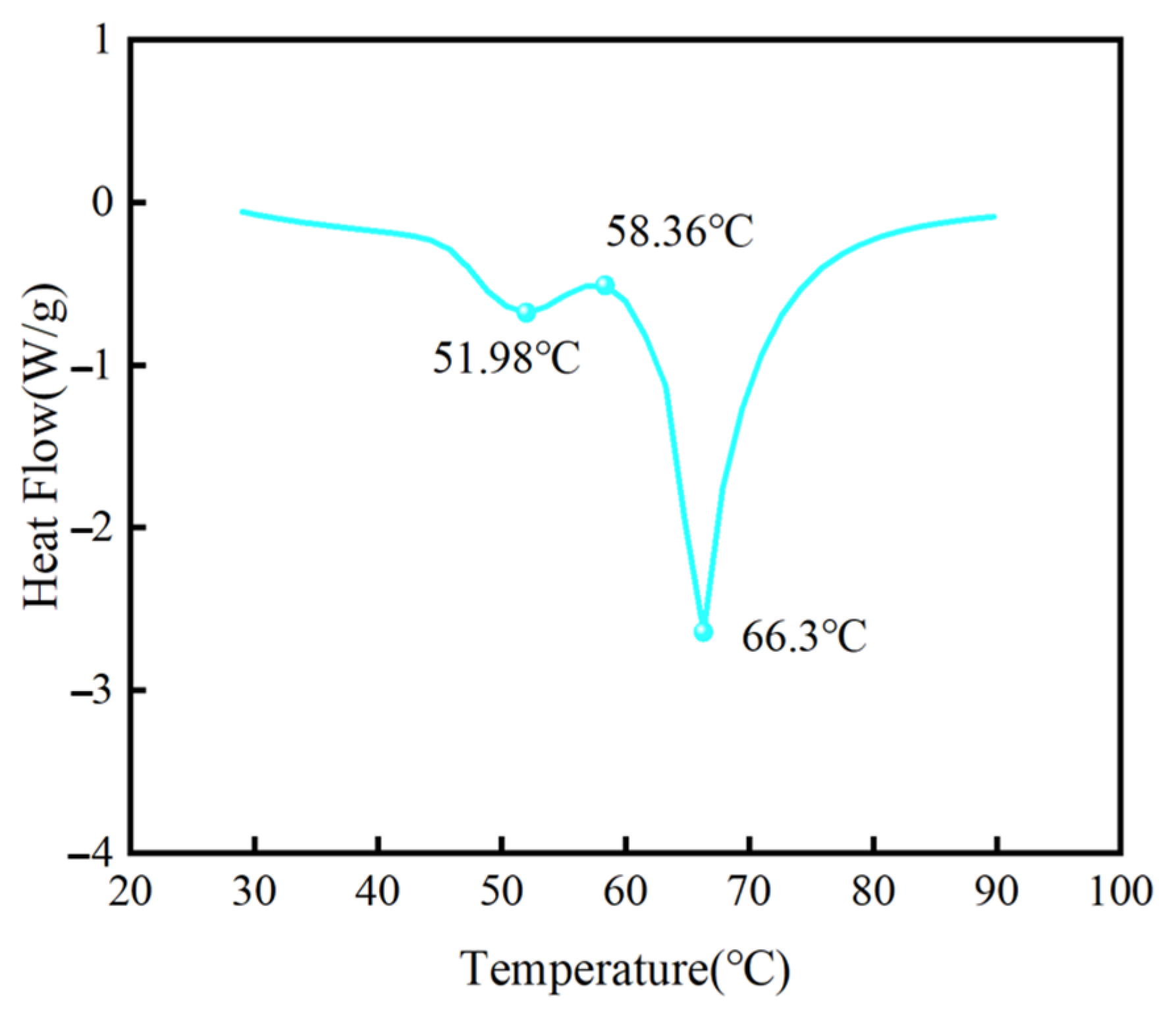
Figure 1. DSC analysis results.
Processes 13 01557 g001
Figure 2. Schematic diagram of the experiment apparatus.
Processes 13 01557 g002
Figure 3. The dimensions of the thermal energy storage module and temperature measurement points inside the PCM: (a) I = Φ89 × 3 mm; (b) II = Φ108 × 3 mm; (c) III = Φ127 × 3 mm.
Processes 13 01557 g003
Figure 4. Timewise variations in the temperatures of the PCM at the same axial. (Inlet temperature of 75 °C, inclination angle of 45°).
Processes 13 01557 g004
Figure 5. Timewise variations in the temperatures of the PCM at location C2 for different diameters. (Inlet temperature of 75 °C, inclination angle of 45°).
Processes 13 01557 g005
Figure 6. Timewise variations in the temperatures of the PCM at location C2 under temperatures of 75 °C (a) and 80 °C (b) at different angles of inclination.
Processes 13 01557 g006
Figure 7. Timewise variations in the temperatures of the PCM at location C2 under angles of 0° (a) and 45° (b).
Processes 13 01557 g007
Figure 8. Timewise variations in the temperatures of the PCM at location C2 under inclination angles of 45° (a) and 90° (b) for different water entrance methods.
Processes 13 01557 g008
Disclaimer/Publisher’s Note: The statements, opinions and data contained in all publications are solely those of the individual author(s) and contributor(s) and not of MDPI and/or the editor(s). MDPI and/or the editor(s) disclaim responsibility for any injury to people or property resulting from any ideas, methods, instructions or products referred to in the content.