Article

Numerical Analysis and Optimization of Residual Stress Distribution in Lined Pipe Overlay Welding

1
School of Materials Science and Engineering, China University of Petroleum (East China), Qingdao 266580, China
2
Petrochina Southwest Oil & Gasfield Company, Chengdu 610051, China
3
School of Mechanical Engineering, Xi’an Shiyou University, Xi’an 710065, China
*
Authors to whom correspondence should be addressed.
Processes 2025, 13(5), 1548; https://doi.org/10.3390/pr13051548 (registering DOI)
Submission received: 19 March 2025 / Revised: 8 May 2025 / Accepted: 15 May 2025 / Published: 17 May 2025
(This article belongs to the Section Manufacturing Processes and Systems)

Abstract

:
This study investigates the thermal and residual stress development in multi-layer lined pipe welding through numerical simulation and experimental validation. The focus is on the weld overlay/liner transition region, a critical area prone to stress concentrations and fatigue crack initiation. Using finite element analysis (FEA) with the Goldak double-ellipsoidal heat source model, the research examines the temperature evolution, residual stress distribution, and deformation characteristics during the welding process. Key findings reveal that the peak temperature in the weld overlay region reaches 3045.2 °C, ensuring complete metallurgical bonding. Residual stresses are predominantly tensile near the three-phase boundary, with maximum von Mises stress observed in the base pipe at 359.30 MPa. This study also employs Response Surface Methodology (RSM) to optimize welding parameters, achieving a 20.5% reduction in residual axial stress and a 58.1% reduction in residual circumferential stress. These results provide valuable insights for optimizing welding processes, improving quality control, and enhancing the long-term reliability of bimetallic composite pipelines.

1. Introduction

Bimetallic composite pipes, typically comprising a corrosion-resistant alloy (CRA) liner metallurgically or mechanically bonded to a carbon steel backing pipe, are extensively used in oil and gas transport systems. These pipes combine the corrosion resistance of CRA materials with the mechanical strength and cost-efficiency of carbon steel, making them ideal for high-pressure and corrosive service environments [1,2,3]. Among the critical fabrication stages, weld overlay cladding at pipe ends ensures the continuity and sealing of the CRA liner, playing a vital role in the structural and operational integrity of the pipeline system.
Numerous studies have explored the welding behavior of composite pipelines, particularly focusing on girth welds. These investigations have provided valuable insights into the thermal cycles, residual stress development, metallurgical transformations, and mechanical response of dissimilar metal joints [4,5,6,7]. For instance, finite element models by Obeid et al. [4,5] and thermal stress analyses by Rizzo et al. [6] have highlighted the significance of heat input control in reducing post-weld deformation and stress accumulation. However, the pipe-end weld overlay/liner transition region—where the weld overlay, liner, and base pipe converge—presents unique challenges. This three-phase boundary involves highly mismatched materials in terms of thermal conductivity, expansion, and yield strength, which can lead to severe stress localization, solidification defects, and delamination risks [8,9,10,11].
Recent research has identified this transition zone as a high-risk area for fatigue crack initiation and failure. Experimental fatigue testing by TWI Ltd. and others [12,13,14] classified typical failure modes such as cracks propagating along the liner–weld interface or into the overlay. However, most of these studies have emphasized qualitative failure observations or simplified analytical modeling. For example, Fu et al. [12] and Pepin et al. [15] reported fatigue crack development near the weld interface but lacked detailed thermo-mechanical coupling analyses to correlate residual stress with crack behavior. Similarly, while Tkaczyk et al. [16] investigated liner wrinkling under deformation, their work did not fully capture the thermal stress accumulation during multi-pass welding.
To date, few studies have integrated high-fidelity thermal–mechanical simulations with multi-layer welding process modeling in the pipe-end overlay region. Moreover, the optimization of welding parameters for minimizing residual stress at the three-phase boundary remains largely unexplored. This gap limits the industry’s ability to proactively control residual stress and improve weld integrity in demanding applications. The schematic cross-section in Figure 1 illustrates the geometry of the lined pipe, highlighting key components such as the outer pipe, the mechanical fit, the girth weld, and the weld overlay transition region [14,17]. This configuration is crucial for understanding the structural integrity and fatigue behavior of mechanically lined pipes, particularly in sour service environments.
The transition point between the liner and weld overlay is of particular interest due to its potential role as a stress concentration site under fatigue loading. Previous studies, including those by Focke [18] and Tkaczyk [15,16,19] have investigated the fatigue behavior at this interface, noting that cracks often initiate at the weld overlay/liner transition point and may propagate into either the backing steel or the CRA liner. This underscores the importance of detailed inspection and quality control in the manufacturing and application of mechanically lined pipes to ensure their reliability in demanding operational conditions. Through the fatigue test results of the lined pipe, four types of flaws relevant to lined pipes were identified by TWI Ltd., where cracks initiate from the weld/overlay transition point [20]. Type I cracks propagate into the outer pipe, Type II cracks extend from the transition point into the liner, Type III cracks propagate along the interface between the liner and the weld overlay, and Type IV cracks extend from the transition point into the weld overlay. These flaw types are summarized in Figure 2.
Despite the critical importance of pipe-end overlay welding, research in this area remains in its early stages. Existing studies indicate that the weld overlay/liner transition region exhibits high residual stress concentrations, significantly affecting the fatigue and corrosion resistance of composite pipelines [14]. Furthermore, most numerical simulations and experimental studies have focused on girth welding, leaving a significant gap in understanding how welding parameters influence the thermal and mechanical behavior of the weld overlay/liner transition region [21].
To address these issues, this study performs a detailed numerical analysis of residual stress evolution during multi-layer weld overlay cladding in bimetallic composite pipes. A three-dimensional finite element model incorporating the Goldak double-ellipsoidal heat source is developed to simulate the welding process and evaluate the temperature distribution and stress field evolution. Special focus is placed on the weld overlay/liner transition region, where thermal mismatch and mechanical constraint are most critical. In addition, a multi-objective optimization approach based on Response Surface Methodology (RSM) is employed to identify optimal welding parameters that minimize axial and circumferential residual stresses. The results provide theoretical guidance for welding design and residual stress mitigation, contributing to the improved fatigue resistance and service life of lined pipeline systems.

2. Numerical Modeling

2.1. Finite Element Modeling Approach

In this study, the base pipe is a seamless steel pipe made of X52 material, with an outer diameter of 323.8 mm and a wall thickness of 10 mm. The liner pipe is made of N08825 material, with an outer diameter of 303 mm and a wall thickness of 3 mm. The geometric parameters and welding sequence of the composite pipe are shown in Figure 3.
At one end of the composite pipe, weld overlay cladding is applied over a length of 50 mm, with a total overlay thickness of approximately 3.5 mm. The base pipe thickness in the weld overlay region is 9.5 mm. At the inner edge of the weld overlay region, both the 0.5 mm thick base pipe and the liner pipe are chamfered at a 123° angle, ensuring that the chamfered surfaces are flush. The weld overlay is performed using S355J2G3-MPM-sw material, applied in two layers to achieve an overlay surface that is nearly level with the inner surface of the liner pipe. The welding parameters are set as follows: welding current: 100 A; voltage: 17 V; welding speed: 5 mm/s.
Using Simufact Welding 2024 software (Hamburg, Germany), based on the geometric characteristics and welding sequence of the composite pipe, second-order hexahedral elements were used for both thermal and mechanical analyses. Each node in the model includes temperature degrees of freedom (DOFs) and three translational DOFs. The same mesh, nodes, and elements were employed for both thermal and mechanical analyses, ensuring consistent grid distribution across the simulations. The final finite element model consists of 95,672 nodes and 73,974 elements. The finite element model is shown in Figure 4.
To accurately capture the thermal gradients and stress concentrations, local mesh refinement was applied in the fusion zone (FZ), the heat-affected zone (HAZ), and the weld overlay region of the base pipe. Additionally, mechanical boundary conditions were set to restrict axial displacement at the pipe ends to simulate actual clamping conditions. These settings enable the simulation to accurately predict heat input, temperature distribution, deformation, and residual stress during the welding process, ensuring that the model closely represents real-world conditions.
During the welding process, the composite pipe remains fixed, while the heat source moves along a circumferential path at a constant speed. The weld overlay consists of two layers, each completed in a single pass. The entire overlay welding process is performed in sequential passes, with sufficient interpass time allowed between weld layers and the girth weld, enabling natural cooling to the target maximum interpass temperature of approximately 100 °C.
The welding sequence begins at a central angle of θ = 0° and progresses in a counterclockwise direction, stopping at θ = 360° after completing a full pass. This approach ensures uniform heat distribution and the accurate simulation of thermal and mechanical effects during the welding process.
The heat input was automatically calculated based on welding current, voltage, welding speed, and a default heat efficiency of 0.9. The material properties were sourced from a material database, defining the following: Base pipe (X52 steel): latent heat of 247 kJ/kg (solidus temperature 1440 °C; liquidus temperature 1560 °C). Liner pipe (N08825): latent heat of 260 kJ/kg (solidus temperature 1340 °C; liquidus temperature 1390 °C). Weld overlay material (S355J2G3-MPM-sw): yield strength values matched according to the database. The thermo-mechanical properties of three materials are shown in Table 1, Table 2, and Table 3, respectively.

2.2. Heat Source Model

Accurately modeling the heat input during welding is essential for predicting temperature distribution, residual stresses, and weld bead geometry in numerical simulations. In this study, the Goldak double-ellipsoidal heat source model was adopted to simulate the moving heat source and its interaction with the composite pipe material. This model has been widely used in welding simulations due to its ability to represent asymmetric heat distribution in the leading and trailing regions of the molten pool, making it particularly suitable for arc welding processes [4,6,22].
The Goldak heat source model divides the heat input into two three-dimensional ellipsoidal regions. The volumetric heat flux distribution q ( x , y , z ) in each region follows the Gaussian function [21]:
q f x , y , z = 6 3 f f Q π a b c f exp 3 x 2 a 2 3 y 2 b 2 3 z 2 c f 2
q r ( x , y , z ) = 6 3 f r Q π a b c r exp 3 x 2 a 2 3 y 2 b 2 3 z 2 c r 2
where q f is the front ellipsoid, which represents the heat distribution in the preheated material ahead of the arc. q r is a rear ellipsoid, which accounts for the heat absorption in the molten pool and solidified weld metal. Q is the total heat input, calculated as Q = η V I , where η is the heat efficiency, V is the voltage, and I is the welding current. f f and f r are the fractions of heat input distributed to the front and rear ellipsoids, respectively, where f f + f r = 2 . a and b define the radial dimensions of the heat source. c f and c r are the axial dimensions of the front and rear ellipsoids, respectively.
The schematic diagram of the double-ellipsoidal heat source is shown in Figure 5. af is the front axis length, ar is the rear axis length, b is the heat source width, and d is the heat source depth. The specific parameters used for the double-ellipsoidal heat source in this study are listed in Table 4, based on empirical values and experimental calibration [23].
To ensure the accurate representation of the arc energy deposition, the welding heat input was calculated using the following formula:
Q = η V I
where the welding efficiency η is set to 0.9, considering the heat losses due to convection and radiation. The welding parameters are 100 A, 17 V, and a welding speed of 5 mm/s, resulting in a calculated heat input of 1.53 kJ/mm. The heat distribution coefficients for the Goldak model were set as f f = 0.6 and f r = 1.4 , ensuring greater heat concentration in the rear ellipsoid, which better represents the experimental observations of the molten pool behavior. The thermal boundary conditions applied include the following: ambient temperature: 25 °C; convective heat transfer coefficient: 10 W/(m2·K); radiative emissivity: 0.9.
The heat source moves along the circumferential direction of the pipe at a constant speed, following the welding sequence illustrated in Figure 3. A layer-by-layer approach is implemented, allowing sufficient cooling between passes to accurately simulate multi-pass weld deposition and the interpass temperature effect.

3. Simulation Results and Analysis

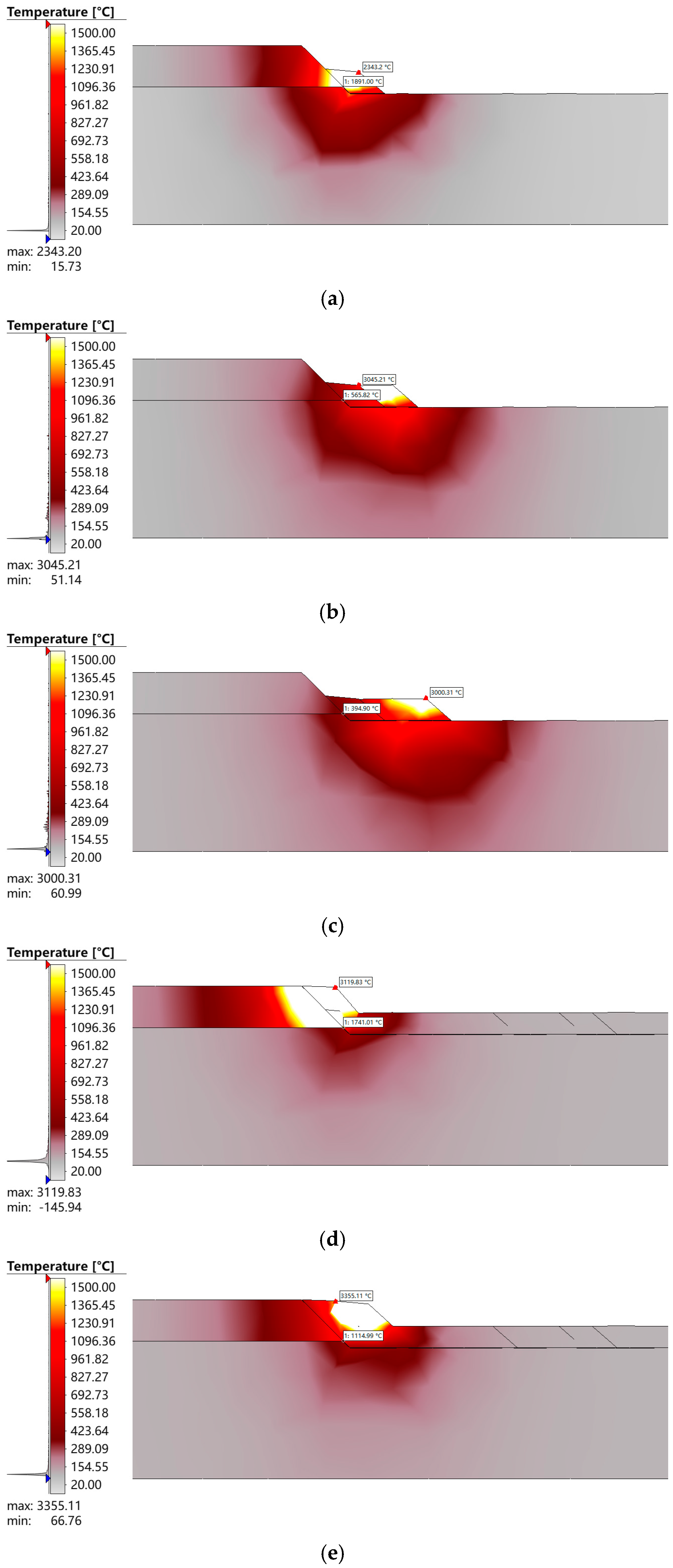
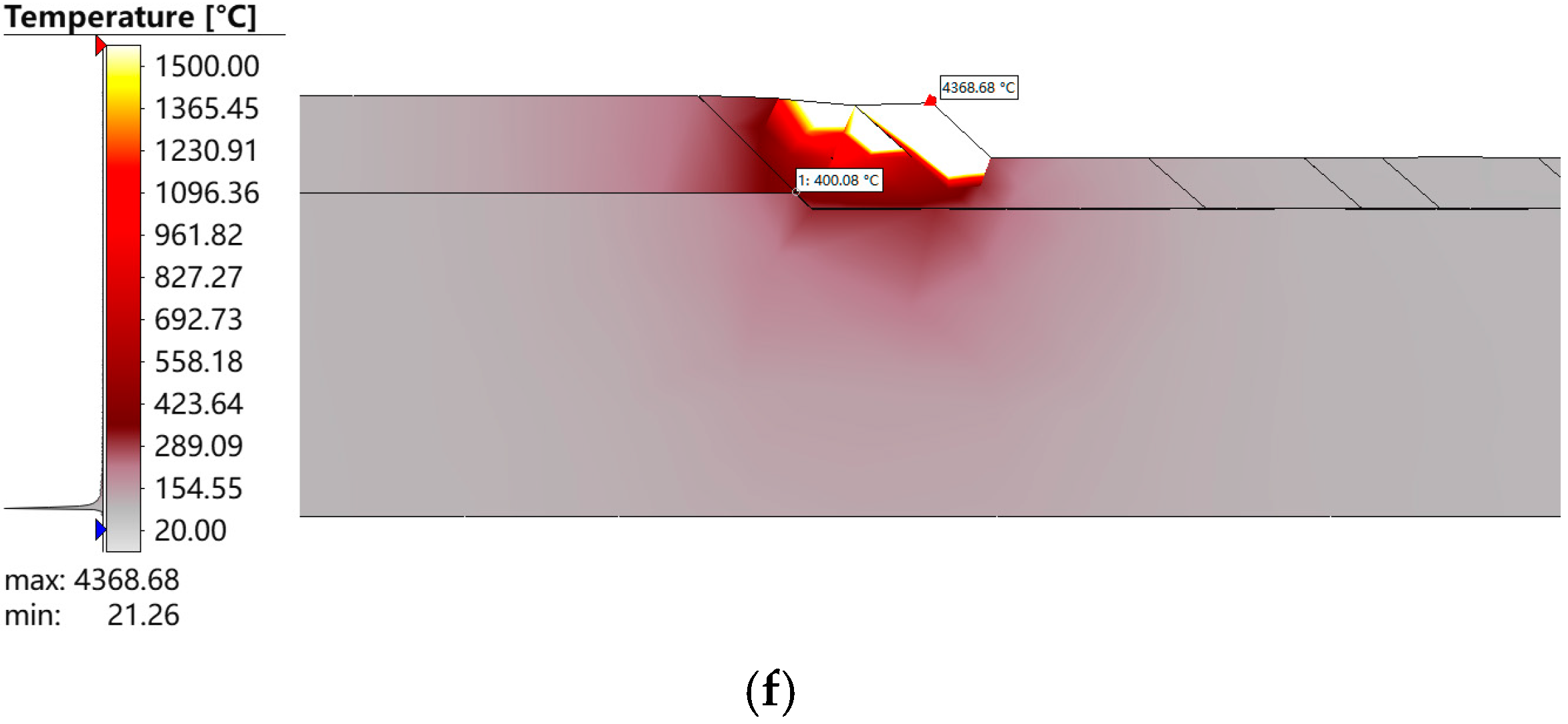
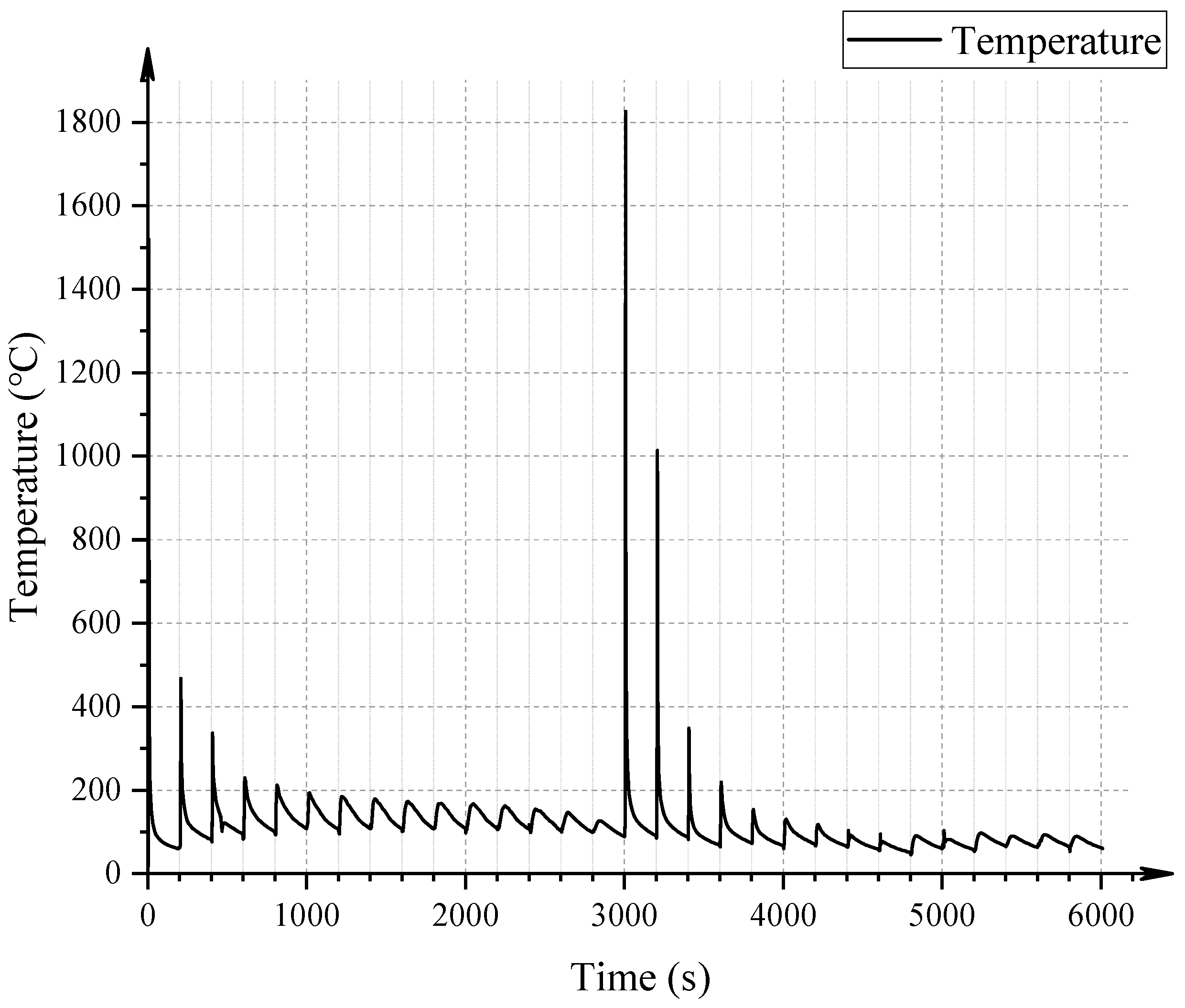
3.1. Temperature Field Distribution and Evolution

Using the welding dimensions shown in Figure 3 and selecting the double-ellipsoidal heat source parameters in Table 4, the optimized welding conditions for the weld overlay cladding of the composite pipe were determined as follows: a welding current of 100 A, a voltage of 17 V, and a welding speed of 5 mm/s. A numerical simulation of the temperature field evolution during the welding process was conducted to analyze the thermal behavior and its influence on the structural integrity of the composite pipe.
Figure 6 presents the simulated temperature field distributions for the first and second layers of weld overlay, focusing on the first three weld passes. As shown in Figure 6a–f, the peak temperature reached during the first layer of the weld overlay was 3045.2 °C, indicating significant heat input into the fusion zone. This temperature is well above the melting point of both the base pipe (X52 steel) and liner material (N08825), ensuring complete metallurgical bonding.
Additionally, to further investigate the thermal behavior in the critical transition zone, the temperature variation at the weld overlay/liner transition region was extracted throughout the entire welding process. As shown in Figure 7, at approximately 3000 s, during the weld pass labeled as 2-1, the temperature at the three-phase boundary reached its peak value of 1835.2 °C. The results in Figure 2 illustrate the temperature evolution at the three-phase boundary during multi-pass welding. These data provide critical insights into the thermal cycling effects experienced at the interface, which can directly impact the formation of residual stresses and potential defect formation.
These findings contribute to a comprehensive understanding of the thermal effects in weld overlay cladding, providing a basis for optimizing welding parameters and minimizing thermal-induced defects in bimetallic composite pipe welding.

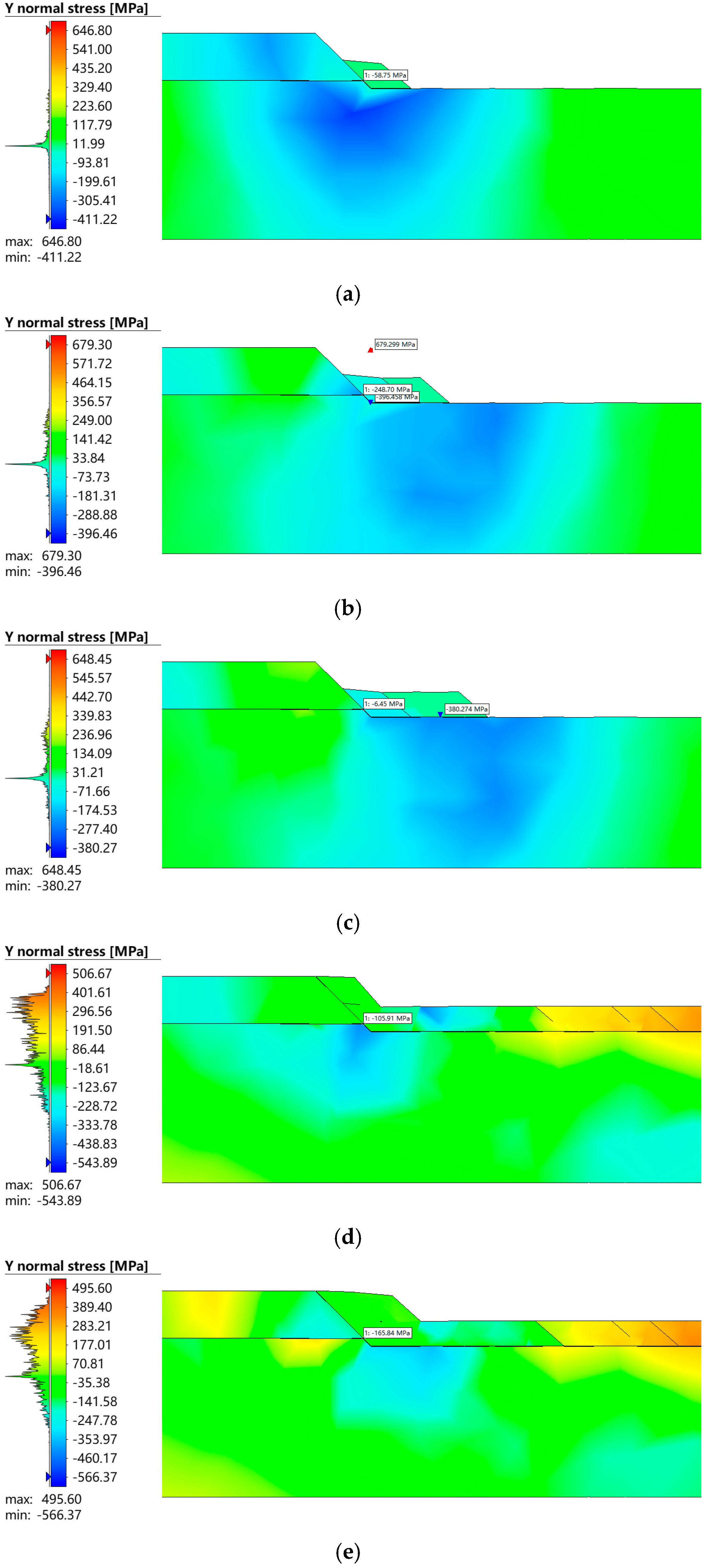
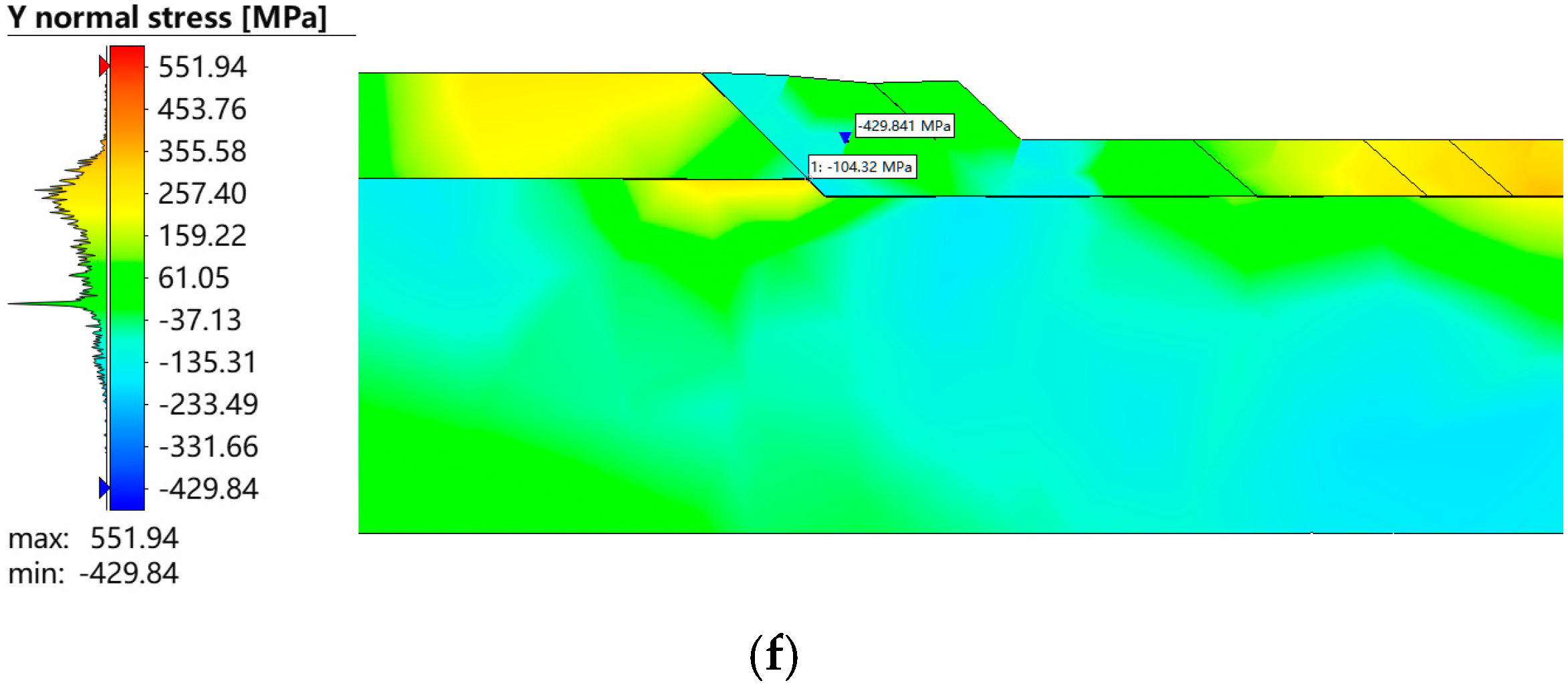
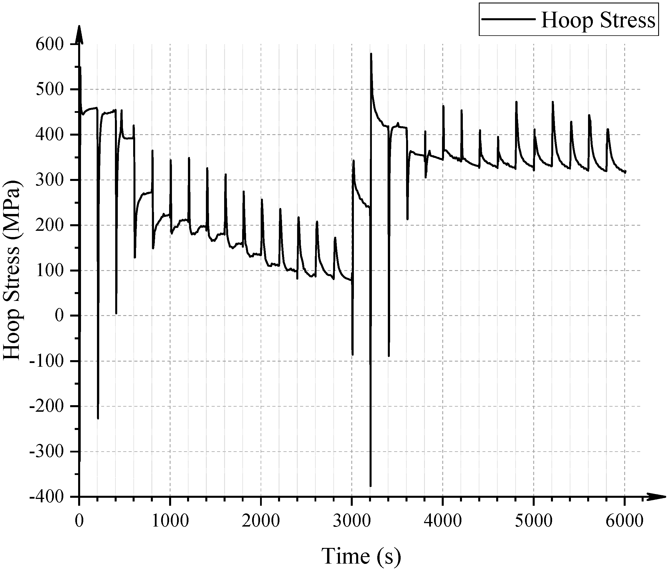
3.2. Residual Stress Field Analysis

Using the same welding process and parameters as in the temperature field analysis, a numerical simulation of the post-weld residual stress distribution was conducted. The evolution of circumferential residual stress during the multi-layer weld overlay process was examined to assess stress development in the critical weld overlay/liner transition region. Figure 8 illustrates the contour plots of the hoop stress field near the three-phase boundary (weld overlay, liner, and base pipe) after each weld pass. It is evident that as welding progresses, each subsequent layer significantly alters the local stress field. Specifically, after the completion of the first-layer welds (passes 1-1 to 1-3), the circumferential stress distribution in the vicinity of the three-phase interface exhibits a compressive tendency, indicating the influence of thermal contraction during cooling. However, with the addition of the second-layer welds (passes 2-1 to 2-3), the stress state transitions toward tensile, with stress concentrations emerging more prominently along the fusion lines and in the adjacent regions of the liner and weld metal.
Figure 9 further quantifies the temporal evolution of hoop stress at the three-phase boundary throughout the entire welding process. The plot demonstrates that each weld pass imposes a distinct influence on the circumferential stress at this critical location. Following the initial welds, the hoop stress fluctuates but generally remains compressive or near-zero. Notably, after the deposition of the second-layer welds, a significant tensile stress state develops. At the end of the final weld pass, the circumferential stress at the three-phase boundary stabilizes at approximately 300 MPa, reflecting the cumulative thermal and mechanical effects of the full weld sequence. This tensile residual stress magnitude is a critical indicator of potential crack initiation sites and underscores the need for the precise control of welding parameters to mitigate stress concentration effects.
In order to comprehensively characterize the residual stress behavior in the weld overlay/liner transition region, additional analyses were performed on the spatial distributions of hoop stress (Figure 10 and Figure 11), axial stress (Figure 12 and Figure 13), and von Mises equivalent stress (Figure 14 and Figure 15). Each stress component was visualized through contour maps followed by line profile extraction along the three-phase interface, enabling a detailed comparison among the liner, weld overlay, and base pipe materials.
The contour maps revealed that all three stress components exhibit clear localization and gradients near the material interfaces, with stress concentrations forming predominantly in the weld overlay and base metal zones. For hoop stress, the weld overlay region consistently showed peak tensile values exceeding 350 MPa, while the liner maintained comparatively lower stress magnitudes. Similarly, the axial stress field demonstrated a distinct peak near the fusion boundary, with tensile stresses reaching up to 320 MPa in the weld metal and base pipe, whereas the liner experienced a more moderate stress level.
The von Mises stress distribution further confirmed these trends, highlighting critical zones susceptible to failure. The equivalent stress peaked at approximately 359 MPa in the base pipe directly adjacent to the three-phase boundary, while the liner and weld overlay exhibited maximum equivalent stresses of 291 MPa and 250 MPa, respectively. Notably, the peak equivalent stress locations did not always coincide with the geometric transition point but were found to be offset by approximately 4 mm along the axial direction, indicating the influence of thermal gradients and mechanical constraints during cooling.
These results collectively demonstrate that the residual stress field is highly heterogeneous across the transition region, with the highest tensile stresses localized in the weld overlay and base pipe near the fusion interfaces. This stress distribution pattern may act as a driving force for crack initiation and propagation, particularly under service conditions involving cyclic loading or corrosive environments. The effective mitigation of these stress concentrations through process optimization is thus essential for improving the structural reliability of bimetallic composite pipe joints.
In summary, the numerical analysis of residual stresses in the weld overlay/liner transition region reveals that the multi-layer welding process induces significant tensile stress accumulation, especially within the weld overlay and adjacent base pipe material. Among the three evaluated stress components—hoop stress, axial stress, and equivalent von Mises stress—the highest values are predominantly located at or near the fusion boundaries, with magnitudes in excess of 350 MPa. These localized tensile stresses, particularly those concentrated around the three-phase interface, present a critical risk factor for crack initiation under service conditions. The stress field is not uniformly distributed but rather exhibits pronounced gradients and peak shifts, highlighting the complex thermo-mechanical interactions during welding and subsequent cooling.
These findings emphasize the necessity of targeted welding parameter optimization to reduce residual stress magnitudes and redistribute stress concentrations away from critical interfaces. By controlling heat input, interpass temperature, and deposition sequence, the detrimental effects of tensile residual stress can be mitigated, thereby enhancing the fatigue resistance and structural integrity of bimetallic composite pipes. This insight provides a theoretical foundation for the development of robust, long-life welded joint designs in demanding pipeline applications.

3.3. Multi-Objective Optimization of Weld Overlay Parameters

To mitigate residual stress concentrations in the weld overlay/liner transition region and improve the structural reliability of the composite pipe, a multi-objective optimization strategy was implemented using Response Surface Methodology (RSM). This method enables the efficient modeling of the complex nonlinear relationships between welding parameters and residual stress responses, while reducing the computational cost compared to full-factorial simulations.
Three key process parameters were selected as design variables: welding current (I), voltage (U), and travel speed (v). These parameters directly influence heat input, thermal gradients, and cooling rates, which are primary factors governing the development of residual stress fields. Based on practical welding constraints, their design ranges were defined as follows: current 110–140 A, voltage 20–24 V, and speed 4–6 mm/s.
Quadratic regression models were established to describe the relationship between the input parameters and two response variables: residual axial stress ( σ x ) and residual circumferential stress ( σ y ). The general form of the RSM model is given by:
Y = β 0 +   β i X i +   β i i X i 2 +   β i j X i X j + ϵ
where Y is the response variable (e.g., residual stress σ x or σ y ), X i represents the independent input variables (e.g., I , U , v ), β 0 , β i , β i i , and β i j are regression coefficients, and ϵ is the random error term.
The optimization aims to minimize the residual axial stress ( σ x ) and residual circumferential stress ( σ y ) at the weld overlay/liner transition region after welding. The key process parameters, including welding current ( I ), welding voltage ( U ), and welding speed ( v ), are selected as design variables, while their ranges are constrained based on practical welding conditions; the specific parameters are shown in Table 5.
To optimize the weld overlay process, a multi-objective optimization model is constructed based on the RSM-derived response functions. The objectives are to minimize residual stresses while maintaining feasible welding conditions. The general optimization problem can be expressed as follows:
m i n f 1 ( I , U , v ) , f 2 ( I , U , v )
subject to:
110   A I 140   A ,   20   V U 24   V ,   4   mm / s v 6   mm / s
where f 1 ( I , U , v ) represents the residual axial stress ( σ x ), f 2 ( I , U , v ) represents the residual circumferential stress ( σ y ), and I , U , v are the design variables.
The numerical solution is obtained using an iterative optimization algorithm, such as the multi-objective genetic algorithm (MOGA) or sequential quadratic programming (SQP), to determine the optimal welding parameters that minimize residual stresses.
Based on the weld overlay numerical simulation model established in Section 3.1, a parametric study was conducted to evaluate the effect of welding current ( I ), welding voltage ( U ), and welding speed ( v ) on the residual stress distribution in the weld overlay/liner transition region. By systematically varying these welding parameters, the minimum residual axial stress ( σ x ) and minimum residual circumferential stress ( σ y ) under different welding conditions were obtained through numerical simulations.
To determine the optimal welding parameters, an orthogonal experimental design was employed to systematically analyze the influence of each factor on residual stress. The results of the orthogonal test analysis were further used to derive an objective function for the minimum residual axial stress ( σ x ), expressed as follows:
σ x = 820.11 4.12 I + 2.90 U + 9068.93 1 v + 0.43 I U 21.89 I v 275.28 U v x = I , U , 1 v , σ x
The welding current ( I ) has a significant impact on the minimum residual axial stress ( σ x ), while the welding voltage ( U ) exhibits a highly significant effect on σ x . Additionally, the welding speed ( v ) also has a significant influence on σ x . The fitted regression equation satisfies statistical validation criteria, demonstrating good adaptability and predictive accuracy.
The combined effect of welding current ( I ), welding voltage ( U ), and welding speed ( v ) on the minimum residual axial stress ( σ x ) is illustrated in Figure 16, which provides a comprehensive visualization of the interaction among key welding parameters in determining the residual stress distribution in the weld overlay region.
Using the same methodology, the objective function for the minimum residual circumferential stress ( σ y ) was obtained as follows:
σ y = 903.01 6.88 I + 30.03 U + 11211.48 1 v + 0.48 I U 10.31 I v 441.34 U v x = I , U , 1 v , σ y
The product of welding current and welding voltage has a significant impact on the minimum residual circumferential stress. The optimized results under the synergistic effect of these three factors are shown in Figure 17.
By combining Equations (1) and (2), the multi-objective optimization function is formulated as follows:
min y = F x = σ x , σ y s . t . f 1 x = σ x = 0 f 2 x = σ y = 0 x = I , U , 1 v , σ x , σ y
The above multi-objective optimization functions were solved numerically to obtain the optimal set of design variables under the given constraints. The results indicate that using a welding current of 110 A, a welding voltage of 22 V, and a welding speed of 4 mm/s minimizes the residual stress. The optimized results are presented in Table 6.
After optimization, the residual axial stress σx at the weld overlay/liner transition region decreased from 312.20 MPa to 248.21 MPa, representing a reduction of 20.5%. Likewise, the residual circumferential stress σy decreased from 4.35 MPa to 1.82 MPa, achieving a 58.1% reduction.
These improvements demonstrate the effectiveness of welding parameter optimization in reducing residual stresses, which is crucial for minimizing stress concentration, improving fatigue resistance, and enhancing the long-term structural integrity of the composite pipe joint. The reduction in residual stresses also helps to mitigate the risk of weld-induced cracking and distortion, thereby improving the overall reliability and service performance of the welded structure.

4. Conclusions

This study presented a comprehensive numerical investigation into the thermal and residual stress behavior during multi-layer weld overlay cladding in bimetallic composite pipes. Emphasis was placed on the weld overlay/liner transition region, which is recognized as a critical site for stress concentration and potential failure under service conditions. Key conclusions drawn from the simulation and optimization analyses are as follows:
(1)
Thermal Analysis: The peak temperature during the first-layer weld reached 3045.2 °C, ensuring complete metallurgical fusion between the weld overlay and the base materials. At the three-phase interface, the temperature peaked at 1835.2 °C during the second layer, reflecting intense thermal cycling and differential heating across the dissimilar materials.
(2)
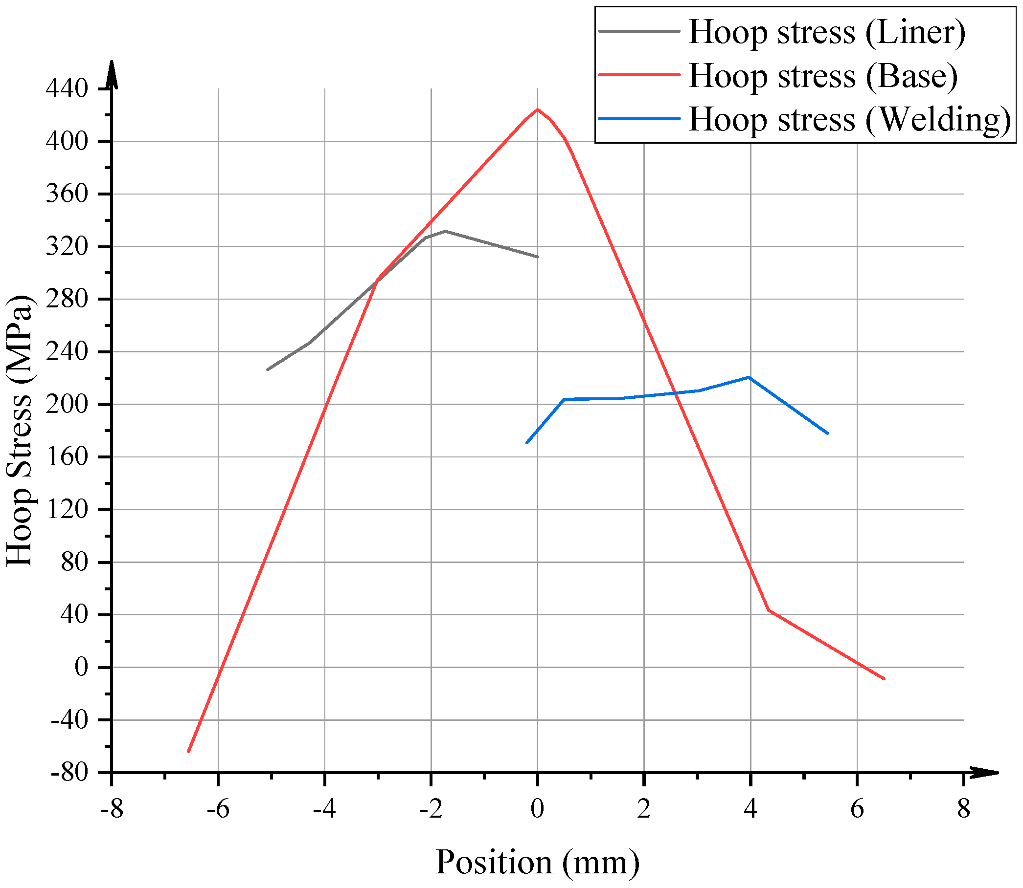
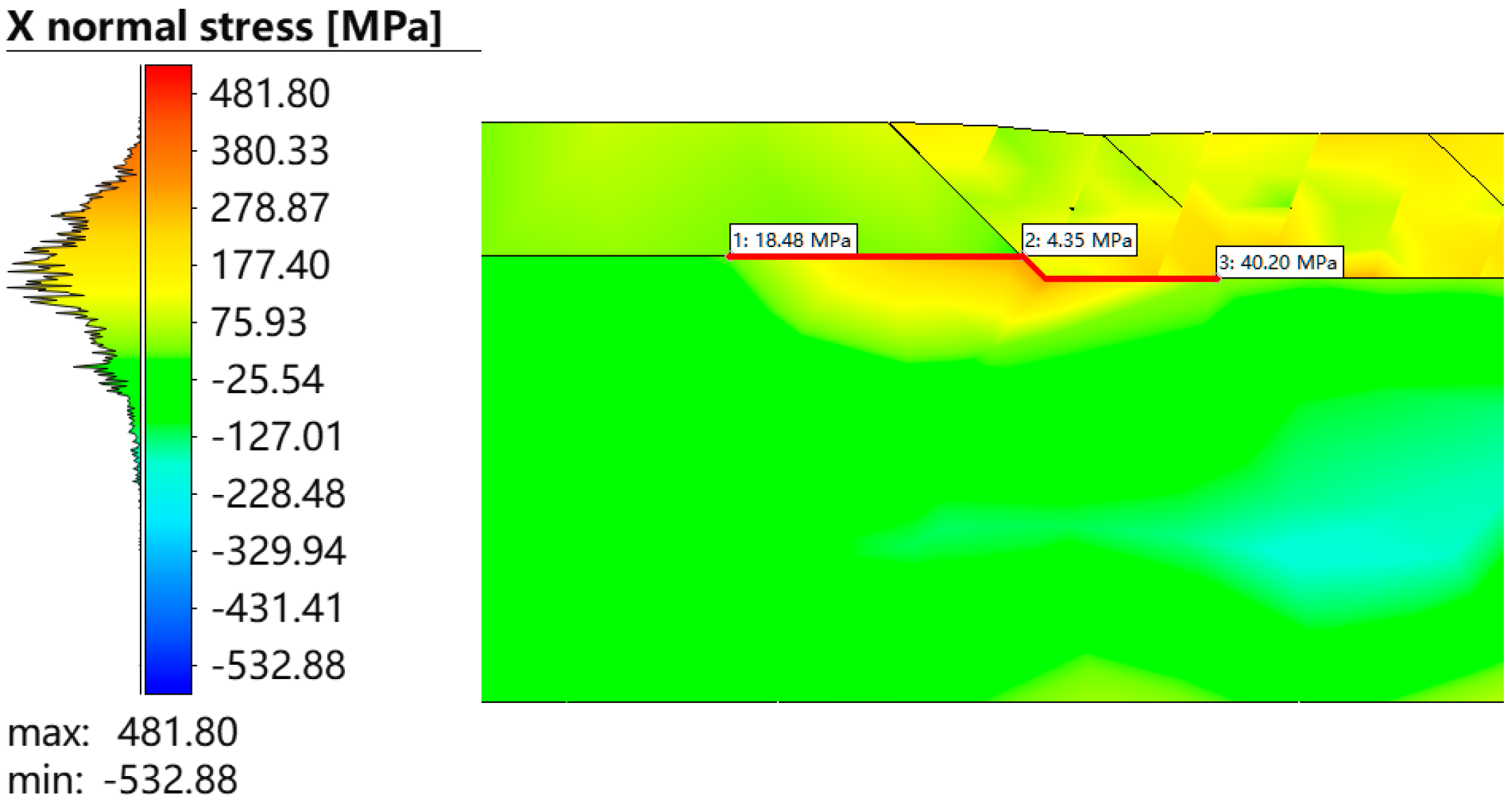
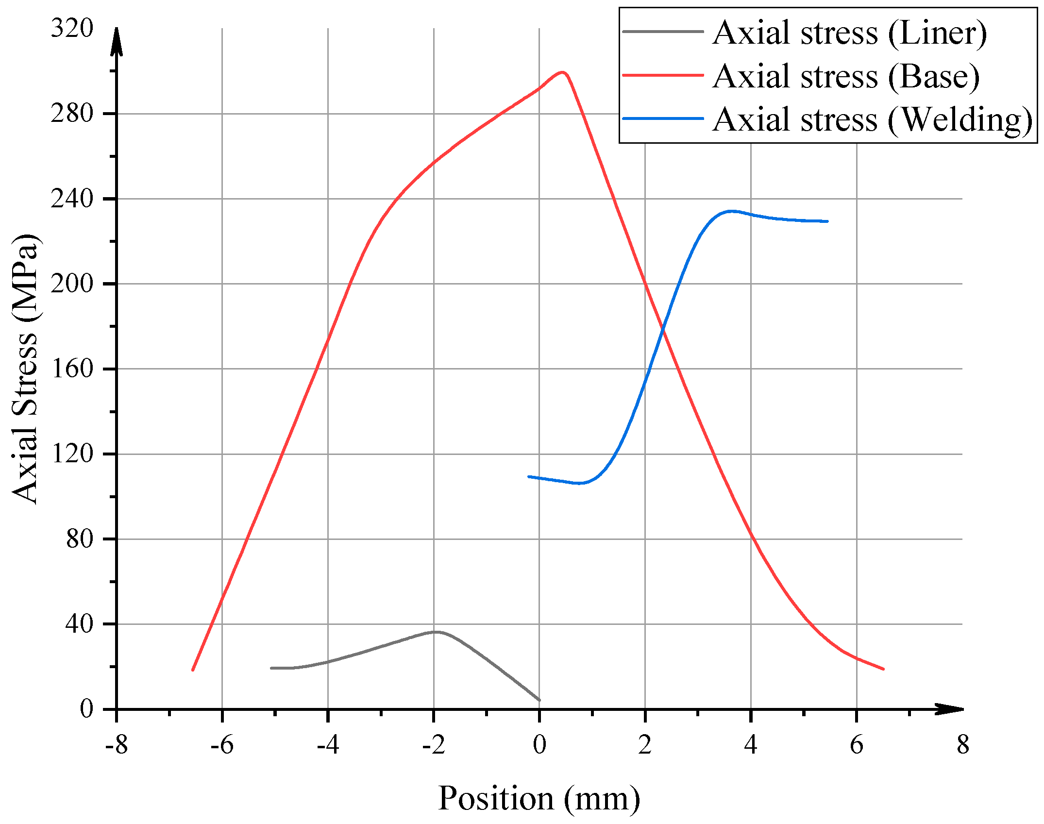
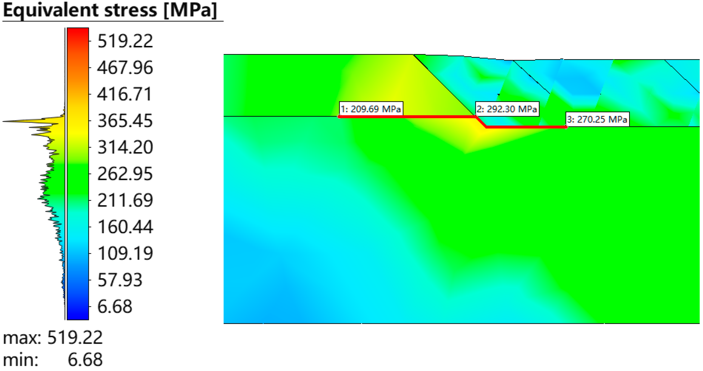
Residual Stress Evolution: Residual stresses in the hoop, axial, and equivalent stress fields exhibited significant gradients and localization around the three-phase boundary. After the second-layer welding, the circumferential stress at the three-phase point reached approximately 300 MPa in tension. The von Mises stress peaked at 359.3 MPa in the base pipe adjacent to the transition zone, while stress peaks in the liner and weld overlay were slightly lower but still significant.
(3)
Optimization of Welding Parameters: Through the application of Response Surface Methodology (RSM) and multi-objective optimization, the welding parameters were tuned to reduce residual stress levels. Optimal conditions were found at 110 A current, 22 V voltage, and 4 mm/s speed, resulting in a 20.5% reduction in axial stress and a 58.1% reduction in circumferential stress.
(4)
Engineering Implications: The findings underscore the importance of precise thermal and process control during weld overlay cladding. Stress localization near material interfaces poses a threat to fatigue life and integrity; however, with optimized welding parameters, these effects can be significantly mitigated. The results provide a theoretical and practical foundation for improving the safety and service performance of mechanically lined pipes in demanding operational environments.
Future work should focus on further validating these results through large-scale experimental tests and exploring the effects of additional welding parameters on weld quality.

Author Contributions

Methodology, Y.S. and S.Y.; software, Y.S.; writing—original draft, Y.S. and T.G.; writing—review and editing, S.Y. and B.W.; supervision, T.G. All authors have read and agreed to the published version of the manuscript.

Funding

The authors are grateful to the support from the Scientific Research Program funded by the Education Department of Shaanxi Provincial Government (24JK0601).

Data Availability Statement

The original contributions presented in this study are included in the article. Further inquiries can be directed to the corresponding authors.

Conflicts of Interest

Author Yuwei Sun was employed by Petrochina Southwest Oil & Gasfield Company. The remaining authors declare that the research was conducted in the absence of any commercial or financial relationships that could be construed as a potential conflict of interest.

References

  1. Gu, T.; Lian, Z.; Dou, Y.; Wu, Z.; Li, G. Simulation and experimental study on liner collapse of lined composite pipe. Int. J. Press. Vessel. Pip. 2024, 207, 105106. [Google Scholar] [CrossRef]
  2. Li, L.; Yu, T.; Xia, J.; Gao, Y.; Han, B.; Gao, Z. Failure analysis of L415/316L composite pipe welded joint. Eng. Fail. Anal. 2024, 158, 107981. [Google Scholar] [CrossRef]
  3. Qu, Y.; Chen, N.-Z.; Yuan, L. Cohesive zone model based reliability analysis for a sandwich pipe. OCEAN Eng. 2023, 270, 113550. [Google Scholar] [CrossRef]
  4. Obeid, O.; Alfano, G.; Bahai, H.; Jouhara, H. Numerical simulation of thermal and residual stress fields induced by lined pipe welding. Therm. Sci. Eng. Prog. 2018, 5, 1–14. [Google Scholar] [CrossRef]
  5. Obeid, O.; Alfano, G.; Bahai, H.; Jouhara, H. A parametric study of thermal and residual stress fields in lined pipe welding. Therm. Sci. Eng. Prog. 2017, 4, 205–218. [Google Scholar] [CrossRef]
  6. Rizzo, R.; Lillebø, B.; Marion, S.; Sverre, E.K.; Eidem, M.A.; Solheim, K.G. The Effect of Reeling on the Qualification of CRA Lined and Clad Pipes According to NACE MR0175/ISO 15156-3: A Methodology to Qualify Reeled Pipelines. In Proceedings of the AMPP CORROSION, Denver, CO, USA, 19–23 March 2023; p. AMPP–2023-18919. [Google Scholar]
  7. Ruggieri, C.; Sarzosa, D.F.; Hippert Jr, E. Fracture resistance testing of pipeline girth welds with strength undermatch using low-constraint specimens. Procedia Struct. Integr. 2019, 18, 36–45. [Google Scholar] [CrossRef]
  8. Gu, T.; Zhang, Q.; Lian, Z.; Yu, H.; Chen, J. Research and application of equivalent pipe model in stress analysis of lined pipe systems. Int. J. Press. Vessel. Pip. 2021, 192, 104418. [Google Scholar] [CrossRef]
  9. Alabtah, F.G.; Mahdi, E.; Eliyan, F.F. The use of fiber reinforced polymeric composites in pipelines: A review. Compos. Struct. 2021, 276, 114595. [Google Scholar] [CrossRef]
  10. Popescu, S.; Montague, P.A. Mechanically lined pipe MLP with improved fatigue resistance. In Proceedings of the Offshore Technology Conference Brasil, Rio de Janeiro, Brazil, 29–31 October 2019; p. D031S041R006. [Google Scholar]
  11. Johnston, C.; Nageswaran, C.; London, T. Investigations into the fatigue strength of CRA lined pipe. In Proceedings of the Offshore Technology Conference, Houston, TX, USA, 2–5 May 2016; p. D011S006R004. [Google Scholar]
  12. Fu, A.Q.; Kuang, X.R.; Han, Y.; Lu, C.H.; Bai, Z.Q.; Yin, C.X.; Miao, J.; Feng, Y.R.; Wei, Y.G.; Tang, Q.; et al. Failure analysis of girth weld cracking of mechanically lined pipe used in gasfield gathering system. Eng. Fail. Anal. 2016, 68, 64–75. [Google Scholar] [CrossRef]
  13. Li, F.G.; Li, X.J.; Li, W.W.; Wang, F.S.; Li, X.M. Failure Analysis and Solution to Bimetallic Lined Pipe. Mater. Sci. Forum 2020, 993, 1265–1269. [Google Scholar] [CrossRef]
  14. Obeid, O.; Leslie, A.J.; Olabi, A.G. Influence of girth welding material on thermal and residual stress fields in welded lined pipes. Int. J. Press. Vessel. Pip. 2022, 200, 104777. [Google Scholar] [CrossRef]
  15. Pépin, A.; Tkaczyk, T.; O’Dowd, N.; Nikbin, K. Low cycle fatigue of subsea mechanically lined pipeline with liner imperfections. In Proceedings of the International Conference on Offshore Mechanics and Arctic Engineering, Trondheim, Norway, 25–30 June 2017; p. V004T003A016. [Google Scholar]
  16. Tkaczyk, T.; Vasilikis, D.; Dywan, B.; Nasikas, A. Comparison for Liner Stability Criteria for Structure Integrity Assessment of Mechanically Lined Pipes During Installation and Subsea Operation. In Proceedings of the ISOPE International Ocean and Polar Engineering Conference, Rhodes, Greece, 6–21 June 2024. [Google Scholar]
  17. Madirisha, M.; Hack, R.; van der Meer, F. Simulated microbial corrosion in oil, gas and non-volcanic geothermal energy installations: The role of biofilm on pipeline corrosion. Energy Rep. 2022, 8, 2964–2975. [Google Scholar] [CrossRef]
  18. Focke, E.S. Reeling of Tight Fit Pipe; Delft University of Technology: Delft, The Netherlands, 2007. [Google Scholar]
  19. Pépin, A.; Tkaczyk, T.; Martinez, M.; O’Dowd, N.; Nikbin, K. Prediction of liner wrinkling during high strain bending of mechanically lined pipe. In Proceedings of the International Conference on Offshore Mechanics and Arctic Engineering, Glasgow, Scotland, UK, 9–14 June 2019; p. V05BT04A017. [Google Scholar]
  20. Sriskandarajah, T.; Roberts, G.; Rao, V. Fatigue aspects of CRA lined pipe for HP/HT flowlines. In Proceedings of the Offshore Technology Conference, Houston, TX, USA, 6–9 May 2013. [Google Scholar]
  21. Deng, D.; Murakawa, H.; Liang, W. Numerical and experimental investigations on welding residual stress in multi-pass butt-welded austenitic stainless steel pipe. Comput. Mater. Sci. 2008, 42, 234–244. [Google Scholar] [CrossRef]
  22. Obeid, O.; Alfano, G.; Bahai, H. Thermo-mechanical analysis of a single-pass weld overlay and girth welding in lined pipe. J. Mater. Eng. Perform. 2017, 26, 3861–3876. [Google Scholar] [CrossRef]
  23. Malik, A.M.; Qureshi, E.M.; Dar, N.U.; Khan, I. Analysis of circumferentially arc welded thin-walled cylinders to investigate the residual stress fields. Thin-Walled Struct. 2008, 46, 1391–1401. [Google Scholar] [CrossRef]
Figure 1. Schematic cross-section showing the lined pipe geometry.
Processes 13 01548 g001
Figure 2. Flaws identified as relevant in lined pipe.
Processes 13 01548 g002
Figure 3. Weld overlay size and welding sequence.
Processes 13 01548 g003
Figure 4. Finite element model for pipe-end weld overlay.
Processes 13 01548 g004
Figure 5. Schematic diagram of double-ellipsoidal heat source.
Processes 13 01548 g005
Figure 6. Contour plot of temperature field evolution in the weld overlay region. (a) Welding number 1-1 (maximum temperature in transition region: 1891.0 °C; for this weld bead: 2343.2 °C). (b) Welding number 1-2 (maximum temperature in transition region: 565.8 °C; for this weld bead: 3045.2 °C). (c) Welding number 1-3 (maximum temperature in transition region: 394.9 °C; for this weld bead: 3000.3 °C). (d) Welding number 2-1 (maximum temperature in transition region: 1741.0 °C; for this weld bead: 3119.8 °C). (e) Welding number 2-2 (maximum temperature in transition region: 1114.9 °C; for this weld bead: 3355.1 °C). (f) Welding number 2-3 (maximum temperature in transition region: 400.0 °C; for this weld bead: 4368.7 °C).
Processes 13 01548 g006aProcesses 13 01548 g006b
Figure 7. Temperature variation at the weld overlay/liner transition region.
Processes 13 01548 g007
Figure 8. Contour plot of circumferential stress field evolution in the weld overlay region. (a) Welding number 1-1 (the residual stress in the transition region is −58.7 MPa). (b) Welding number 1-2 (the residual stress in the transition region is −248.7 MPa). (c) Welding number 1-3 (the residual stress in the transition region is −6.4 MPa). (d) Welding number 2-1 (the residual stress in the transition region is −105.9 MPa). (e) Welding number 2-2 (the residual stress in the transition region is −165.8 MPa). (f) Welding number 2-3 (the residual stress in the transition region is −104.3 MPa).
Processes 13 01548 g008aProcesses 13 01548 g008b
Figure 9. Circumferential stress variation at the weld overlay/liner transition region.
Processes 13 01548 g009
Figure 10. Residual circumferential stress distribution in the three-phase region.
Processes 13 01548 g010
Figure 11. Distribution curve of residual circumferential stress on the three-phase interface.
Processes 13 01548 g011
Figure 12. Residual axial stress distribution in the three-phase region.
Processes 13 01548 g012
Figure 13. The distribution curve of residual axial stress on the three-phase interface.
Processes 13 01548 g013
Figure 14. Von Mises stress distribution in the three-phase region.
Processes 13 01548 g014
Figure 15. The distribution curve of von Mises stress on the three-phase interface.
Processes 13 01548 g015
Figure 16. Minimum residual axial stress (σx) under the synergistic effect of design variables. (a) Influence of I and U on σx. (b) Influence of I and v on σx. (c) Influence of U and v on σx.
Processes 13 01548 g016
Figure 17. Minimum residual circumferential stress ( σ y ) under the synergistic effect of design variables. (a) Influence of I and U on σy. (b) Influence of I and v on σy. (c) Influence of U and v on σy.
Processes 13 01548 g017aProcesses 13 01548 g017b
Table 1. Thermo-mechanical properties of X52.
Temperature\°CYoung’s
Modulus\105 MPa
Poisson’s RatioYield Stress\MPaThermal
Expansion\×10−5 °C−1
Specific Heat\J/kg·°CConductivity\W·m−1·K−1
−292.060.30358.531.12546050.12
212.030.30358.531.1546249.87
382.020.30358.531.1646349.66
931.990.30358.531.2146849.00
1211.970.30358.531.2247048.67
2501.890.31287.841.3148047.23
5001.740.31240.981.4857540.53
7501.590.31107.11.6562527.66
10001.430.3180.331.8267530.13
15001.130.3116.072.1665035.25
20000.820.3110.982.5082014.34
Table 2. Thermo-mechanical properties of N08825.
Temperature\°CYoung’s
Modulus\105 MPa
Poisson’s RatioYield Stress\MPaThermal
Expansion\×10−5 °C−1
Specific Heat\J/kg·°CConductivity\W·m−1·K−1
−291.990.302751.31404.6354
211.970.302751.35406.5254
381.960.302731.36408.2254
931.920.302721.39409.6352
1211.910.302691.4410.5551
2501.840.302401.45422.2249
5001.710.312011.53505.7942
7501.580.31891.61549.7729
10001.450.32671.69593.7532
15001.180.33131.85571.7637
20000.920.3492.01721.315.4
Table 3. Thermo-mechanical properties of S355J2G3-MPM-sw.
Temperature\°CYoung’s
Modulus\105 MPa
Poisson’s RatioYield Stress\MPaThermal
Expansion\×10−5 °C−1
Specific Heat\J/kg·°CConductivity\W·m−1·K−1
2078152.100.31.26743046
10077942.080.31.29550046
20077682.060.31.33055045
30077421.890.31.36558043
40077171.710.31.40061041
50076911.290.31.43565038
60076650.870.31.47071035
70076390.630.31.50579029
80076130.390.31.54086524
90075760.270.31.57256525
144073190.070.31.73863031
Table 4. Specific parameters of double-ellipsoidal heat source.
ParameterFront Axis Length af\mmRear Axis Length ar\mmWidth b\mmDepth d\mmGaussian
Parameter M
Value1.967.22.773.773.0
Table 5. Optimized design variables and parameter ranges.
Optimized Design VariablesParameter Ranges
Welding current I (A)(110, 140)
Welding voltage U (V)(20, 24)
Welding speed v (mm/s):(4, 6)
Table 6. Results of Optimized Welding Parameters.
Optimization ProjectInitial ValueOptimized Value
Minimum residual axial stress σx (MPa)312.20248.21
Minimum residual circumferential stress σy (MPa)4.351.82
Disclaimer/Publisher’s Note: The statements, opinions and data contained in all publications are solely those of the individual author(s) and contributor(s) and not of MDPI and/or the editor(s). MDPI and/or the editor(s) disclaim responsibility for any injury to people or property resulting from any ideas, methods, instructions or products referred to in the content.

