Article

Recycling Positive Electrode Materials of Li-Ion Batteries by Creating a pH Gradient Within Aqueous Sodium Chloride Electrolyser

School of Physical Science and Technology, ShanghaiTech University, 393 Huaxia Middle Road, Shanghai 201210, China
*
Author to whom correspondence should be addressed.
Processes 2025, 13(5), 1525; https://doi.org/10.3390/pr13051525
Submission received: 16 April 2025 / Revised: 9 May 2025 / Accepted: 12 May 2025 / Published: 15 May 2025
(This article belongs to the Section Environmental and Green Processes)

Abstract

:
Recycling the positive electrode materials of spent Li-ion batteries is critical for environmental sustainability and resource security. To facilitate the attainment of the goal, this study presents a novel approach for recovering valuable metals from positive electrode materials of spent lithium-ion batteries (LIBs) in an H-shaped cell containing aqueous NaCl electrolyte. The process employs hydrochloric acid that could be derived from the chlorine cycle as the leaching agent. The electrolytic device is engineered to generate a high pH gradient, thereby enhancing the leaching of metal elements and eliminating the requirement for external acid or base addition. This green recycling approach adheres to the principles of a circular economy and provides an environmentally friendly solution for sustainable battery material recycling.

1. Introduction

Lithium-ion batteries (LIBs) have become the primary choice of power sources for portable electronic devices and electric vehicles due to their high energy density, long cycle life, and low self-discharge rate [1,2]. By 2040, the demand for electricity from electric vehicles (EVs) alone is expected to reach two terawatt-hours, accounting for approximately 6% of total electricity generation [3]. However, as the demand for these batteries increases, the generation of end-of-life LIB waste is also growing rapidly, posing significant challenges in environmental protection and comprehensive utilization of resources [4]. It has been predicted that the global stockpile of used lithium-ion batteries will surpass 11 million tons by 2030 [5]. In contrast, the current recycling rate of the spent LIBs remains as low as 10% [6]. In this scenario, it is imperative to develop efficient and environmentally friendly methods to recover valuable metals from spent LIBs [7,8].
Various LIB recycling techniques have been extensively studied, including pyrometallurgical [9], hydrometallurgical [10], and bio-metallurgical processes [11]. Among them, hydrometallurgy is regarded as a more favourable approach due to its relatively low energy consumption, enhanced metal recovery efficiency, and reduced contribution to air pollution [12]. Inorganic leaching agents often used to extract metals from LIBs include hydrochloric, nitric, sulfuric, and phosphoric acid [13]. Organic leaching agents include citric acid, oxalic acid, malic acid, and ascorbic acid [14]. Electrochemical pH gradients for recovering metals from waste cathode materials of lithium-ion batteries [15] as well as for direct air capture of carbon dioxide have been systematically investigated in H-shaped neutral water electrolytic cells [16,17]. However, these investigations employed electrolytes such as Na2SO4 or NaNO3, resulting in an acidic solution with a pH value of only around 2 (i.e., H+ concentration of 0.01 M) in the anode chamber of the neutral water electrolyser for the leaching of positive electrode materials of LIBs. It was difficult to reduce the pH further due to the relatively slow generation rate of H+ and the recombination of the H+ generated at the anode and the OH generated at the cathode. Given this issue, the goal of the current study is to achieve a much lower pH in the anode chamber to enhance metal ion leaching efficiency from the positive electrode materials of LIBs.
Among all leaching agents, hydrochloric acid (HCl) is regarded as the most effective because chloride ions (Cl) can destroy the stability of the surface layer of the positive electrode materials of LIBs, while other inorganic or organic acids typically require the use of reducing agents to achieve a similar dissolution [18]. Therefore, there has recently been growing interest in the direct utilization of HCl as an effective leaching agent for metal recovery from waste positive electrode materials of spent LIBs [18,19]. Nevertheless, it is necessary to consider the potential issues associated with it, such as the management of chlorine gas (Cl2), a hazardous byproduct generated in the leaching process (Equation (1)). Notably, in the chlor-alkali process, the Cl2 produced from NaCl aqueous solution electrolysis is considered rather as a valuable product for a wide range of applications (e.g., the production of polyvinyl chloride, organic synthesis, water treatment, and metallurgy) [20,21,22]. Moreover, it is of interest to consider leveraging the reaction between Cl2 gas generated at the anode (Equation (2)) and H2 gas generated at the cathode (Equation (3)) to produce HCl (Equation (4)), which can be utilized to leach the waste positive electrode materials of spent LIBs. Moreover, any Cl2 generated from the leaching reaction (Equation (1)) may be collected to react with H2 and regenerate HCl.
In this work, we present the proof-of-concept demonstration of a new process for recovering metals from waste positive electrode materials of spent LIBs based on electrolytic NaCl aqueous solution inside a two-chamber H-shaped cell (Figure 1). The electrolyser employs a RuO2/IrO2-coated Ti mesh as the anode and a Pt-coated Ti plate as the cathode, which are specifically designed for the commercial chlor-alkali industry. In the anode chamber, the chlorine evolution reaction (CER) occurs to produce gaseous Cl2 (Equation (2)), the majority of which can be collected. A small fraction of the Cl2 dissolves in the solution and reacts with water to produce HCl and HClO (Equation (4)). In the cathode chamber, the hydrogen evolution reaction (HER) occurs to produce H2 and OH at the cathode (Equation (3)). The H2 and Cl2 generated by electrolysis, in principle, can be combined to prepare the HCl, which is added in the aqueous form to the anode chamber for the LiCoO2 dissolution. The anodic pH value can be lowered to below 0.5 (i.e., H+ concentration above 0.32 M), representing a 32-fold increase in H+ concentration compared with that in the neutral water electrolyser with Na2SO4 or NaNO3 electrolyte [15,23,24]. As expressed by Equation (1), the addition of HCl not only provides H+ for leaching the LiCoO2, but also provides the corrosive Cl to reduce the cobalt in LiCoO2 from Co3+ to Co2+, which weakens the Co–O bond. The destabilization of the crystalline lattice facilitates structural breakage and enhances the release of Li+ and Co2+ [25]. The Co2+ dissolved into the electrolyte can migrate from the anode chamber to the cathode chamber, where they are precipitated by the OH to form Co(OH)2, as expressed by Equation (5).
LiCoO2 + 4HCl → LiCl + CoCl2 + 2H2O + 1/2Cl2
2Cl → Cl2 + 2e
2H2O + 2e → H2 + 2OH
Cl2 + H2O → HCl + HClO
Co2+ + 2OH → Co(OH)2
This work innovatively combines the chlor-alkali industry with lithium-ion battery recycling, establishing a chlorine cycle and a high pH gradient, which is different from traditional recycling methods. In contrast to conventional hydrometallurgical methods, our approach involves producing HCl from the H2 and Cl2 generated from the electrolysis of NaCl aqueous solution. This HCl solution is then utilised as a leaching agent for metal recovery from waste positive electrode materials of LIBs in the anode chamber of the electrolyser. By establishing a chlorine cycle and in situ precipitation system, this integrated approach not only minimises the reliance on external acids and bases to the greatest extent, but also minimises waste generation, aligning with the principles of green chemistry and sustainable development. It is worth noting that, since there has been a large number of studies on the generation of HCl [26,27,28,29,30,31], it is not the focus of this study.

2. Experimental Section

2.1. Electrochemical Cell

Figure 1 shows the experimental setup of the electrolyser and the associated working principle. The H-shaped electrochemical cell (H-cell) consisted of two borosilicate glass chambers held together by clamps. The volume of both the anode chamber and the cathode chamber was 200 mL, unless specified otherwise. A commercial RuO2/IrO2-coated Ti-mesh electrode (Dimensionally Stable Anode or DSATM; size: 30 × 50 mm2; Schultai Industrial Technology, Suzhou, China) was used as the anode, while a Pt-coated Ti rod (diameter: 6 mm; Yiwanlin Electronic Technology, Kunshan, China) served as the cathode. The electrodes were immersed in a 5 mol/L NaCl aqueous electrolyte purchased from Aladdin. For each electrolysis experiment, 300 mL of electrolyte was added to the H-cell. A quartz crucible (inner diameter: 39 mm; height: 15 mm; thickness: 1 mm) containing commercial LiCoO2 powders was placed in the anode chamber. To minimise convection and the resulting recombination of H+ with OH while allowing metal cation transport, carbon cloths (thickness: 0.8 mm, Model: EDP-0.8; Haote New Material, Jingzhou, China) were positioned at the intersections of each chamber and the cross tube. Polyethylene terephthalate (PET) high-temperature-resistant tape (thickness: 0.06 mm; high temperature resistance: 200 °C; Shentai Tape Direct Sales General Factory, Shenzhen, China) and alumina rings (OD: 12 mm; OD: 8 mm; height: 16 mm) fixed the carbon cloth in place. The aqueous NaCl electrolysis experiments for recovering positive electrode materials of LIBs were conducted under varying applied currents, temperatures, durations, and solid-to-liquid ratios. The solid-to-liquid ratio was defined as the mass of the original positive electrode material divided by the volume of the aqueous electrolyte added in the anode chamber (150 mL). Gas products from the anode chamber were analysed using a Shimadzu™ GC-2014 GC (Shimadzu Corporation, Kyoto, Japan) equipped with a thermal conductivity detector (TCD).
Electrochemical measurements such as linear sweep voltammetry (LSV) and cyclic voltammetry (CV) scans were performed with a Gamry™ Interface 1010E potentiostat (Gamry, PA, USA). An Ag/AgCl electrode with 3 mol/L KCl solution was used as the reference electrode (Jingke Instrument, Shanghai, China). The pH values of the aqueous electrolytes in both chambers were measured using a double-junction pH probe (Leici Instrument, Shanghai, China).

2.2. Quantification of the Cl2 Produced at the Anode Chamber of the Electrolyser

We investigated two methods for quantifying the concentration of chlorine gas in the exit gas: a direct one and an indirect one. The direct method employed the methyl orange (MO) spectrophotometry, which involved absorbing the Cl2 with KBr solution and measuring the absorption of light at 507 nm to directly determine the Cl2 concentration. The indirect method utilised gas chromatography (GC) to quantify the oxygen content, followed by the calculation of the chlorine gas concentration based on the conservation of total electrons in the reaction. The MO spectrophotometry with the Cary 5000 Ultraviolet–Visible–Near infrared (UV–Vis–NIR) spectrophotometer (Agilent, Shanghai, China). MO spectrophotometry is a widely employed method known for its effectiveness in eliminating the interference of HCl [32]. The reaction of Cl2 with a solution containing KBr results in the formation of Br2, disrupting the molecular structure of methyl orange, and causing the red colour in the acidic solution to fade [33]. The absorbance was measured at a wavelength of 507 nm based on the degree of fading for colourimetric determination. More details can be found in Note S1 and Figure S1 in the Supporting Information. The indirect method involved using 20 mL/min N2 as the carrier gas, and the exit gas from the anode chamber passed through two 100 mL 5 mol/L NaOH absorption solution, then passed through a drying tube containing CaCl2 pellets, and was then directed into the GC to measure the oxygen content (Figure S2).

2.3. Characterisation

X-ray diffraction (XRD) with a Cu target and a θ–2θ geometry was conducted on a Bruker™ D8 diffractometer (Bruker, Beijing, China) to determine the crystalline phase. XRD measurements were scanned in the range of 2θ = 15–80° with an increment of 0.02° and at a scanning rate of 0.2 s/step. Phase identification was performed using the International Diffraction Data Centre (ICDD) Powder Diffraction File (PDF)-4+ database. The surface morphology and elemental distribution of the samples were characterised by scanning electron microscopy (SEM) equipped with energy-dispersive spectroscopy (EDS) on a JEOL SEM IT-500HR (JEOL Ltd., Tokyo, Japan). X-ray photoelectron spectroscopy (XPS) analysis was conducted using a Thermo Fisher Scientific ESCALAB™ 250Xi instrument (Thermo Fisher Scientific, Shanghai, China) to analyse the chemical elements on the surface of the sample. The amounts of metal ions in the sample were determined using inductively coupled plasma spectrometry (ICP-OES, Thermo Scientific ICP-OES iCAP™ 7400, Shanghai, China). The sample solution was prepared by dissolving the sample in concentrated hydrochloric acid (Sinopharm, Shanghai, China, 36.5%) and then diluting it 10 times with deionised water. The leaching efficiency of each metal ion dissolved from the powders was calculated using the following formula:
γ M = c M m c M m c M m × 100 %
The leaching efficiency of M (M: Li, Co, Ni, Mn) is denoted as γ M ; c M and c M represent the content of M in the powders in the anode chamber before and after leaching, respectively; m and m refer to the masses of the powders in the anode chamber before and after leaching, respectively.

3. Results and Discussion

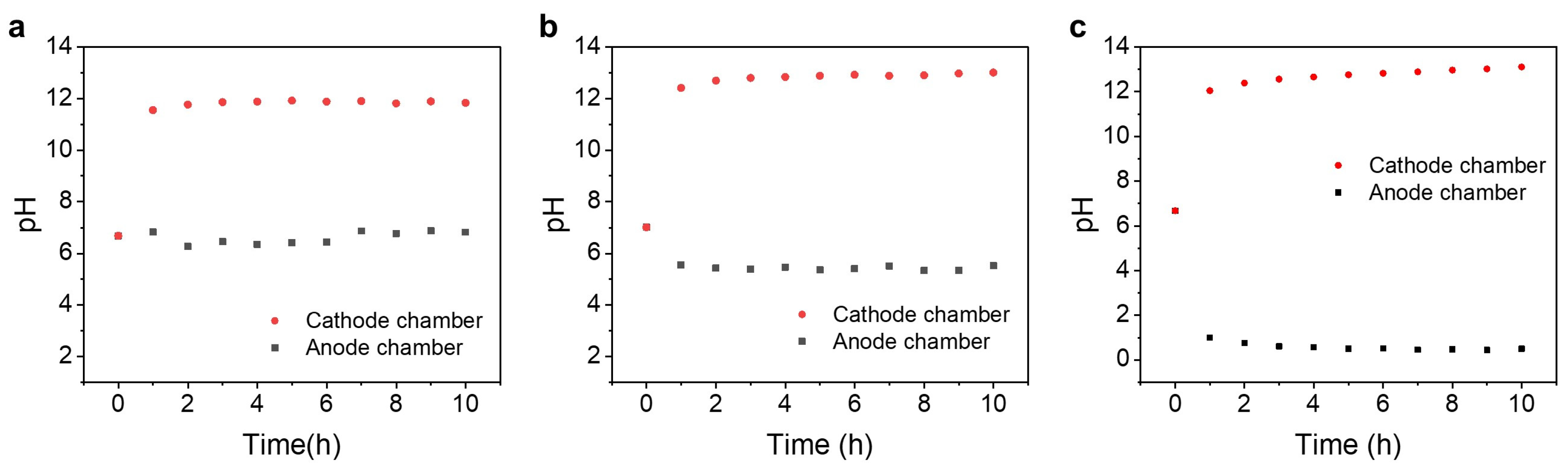
3.1. pH Value Change in the Anode and Cathode Chambers

The pH gradient acts as a critical driving force for both the dissolution of LiCoO2 into the electrolyte and the subsequent precipitation of Co2⁺ as Co(OH)2. This study investigated the pH value change in both the anode and cathode chambers of an H-cell containing 5 mol/L NaCl electrolyte.
Electrolysis experiments were first conducted with neither carbon cloth positioned at the intersections of each chamber with the cross tube nor HCl solution added to the anode chamber, under the conditions of 100 mA current, 85 °C temperature, 5 g/L solid-to-liquid ratio for 10 h. The results revealed that the pH value in the anode chamber was around 6.7 throughout the process, which was too high to leach metal ions from the LiCoO2 powders (Figure 2a). Similar electrolysis experiments were performed with filter papers placed on both sides of the H-cell cross tube and without the addition of HCl solution to the anode chamber. The filter papers gradually deteriorated over a 10 h electrolysis, likely due to the reaction of a small amount of the ClO2 product with lignin, the main component of filter paper (Note S2 and Figure S3) [34].
Electrolysis experiments were also conducted with carbon cloths positioned at the intersection of each chamber with the cross tube but without the addition of HCl solution to the anode chamber under similar conditions (100 mA, 85 °C, 5 g/L) for 10 h. As shown in Figure 2b, the anode chamber pH decreased to ~5, which was insufficient for leaching the LiCoO2. The weak acidity was likely contributed by the occurrence of minor oxygen evolution reaction at the anode (H2O → 1/2O2 + 2H+ + 2e) or the limited dissolution of the Cl2 product into electrolyte, forming HCl and HClO [22]. The carbon cloths were stable during the test and effectively mitigated convection between the two compartments.
To achieve a strongly acidic environment, 2 mol/L HCl solution was continuously added into the anode chamber at 0.93 mL/h of the electrolysis cell with carbon cloths placed on both sides of the cross tube. During a 100 mA electrolysis under a temperature of 85 °C and a solid-to-liquid ratio of 5 g/L, the anode chamber pH reached as low as ~0.5 (highly acidic) after 3 h, while the cathode chamber became strongly alkaline (pH of ~13). A comparison of the results in Figure 2 demonstrates that the use of carbon cloths and the addition of HCl solution into the anode chamber enable the establishment of a large and stable pH gradient during the aqueous NaCl electrolysis. This demonstrates that the carbon cloth effectively maintains the pH gradient throughout the entire electrolysis process.

3.2. Quantification of the Cl2 Product

Due to the selectivity challenge of the chlor-alkali electrolytic anode, the oxygen evolution reaction (OER) competes with the chlorine evolution reaction (CER). The methyl orange (MO) spectrophotometry was used to evaluate the CER selectivity of the DSA anode in the H-cell (Figure 1). MO appears red under acidic conditions (pH < 3.1) due to the presence of azo groups (–N=N–) and sulfonic acid groups (–SO3H) that remain protonated in the acidic environment [35]. Cl2 with strong oxidising property can oxidise Br to Br2, which reacts with the MO to disrupt its original conjugated structure; this reduces the absorption of green light at 507 nm and thereby causes the red colour of MO to fade (Note S1 and Figure S1).
A 100 mA electrolysis experiment was performed at 85 °C for the 5 mol/L aqueous NaCl electrolyte using the setup illustrated in Figure 1. The gas product from the anode chamber was directed to the KBr solution to absorb the Cl2. The amount of Cl2 was quantified using the standard curve method (Figure S2). From the absorbance value of the sample solution, the selectivity of generating Cl2 at the anode was estimated to be only 35.9%—well below the theoretical value. This discrepancy was attributed to various factors, such as the solubility of chlorine gas in the aqueous solution of the anode chamber, the chemical reactions between the anode anodic product of Cl2 and the NaOH transported from the cathode chamber during the convective process, as well as incomplete reaction between the Cl2 and the KBr in the absorption solution.
Consequently, we resorted to an indirect measurement approach. The GC analysis of the exit gas from the anode chamber of the H-cell (Figure S2) revealed that a small signal for O2 was observed, suggesting very high selectivity (99.2%) of CER. This was consistent with the previous studies. For example, it has been demonstrated that increasing the Cl concentration and decreasing the pH of the solution can enhance the selection efficiency of CER on the DSA electrode [36]. Another previous work has also reported that under conditions of NaCl concentration of 5 mol/L, pH of 2, and CER overpotential of 100 mV, the selectivity of CER can achieve 95% [37].

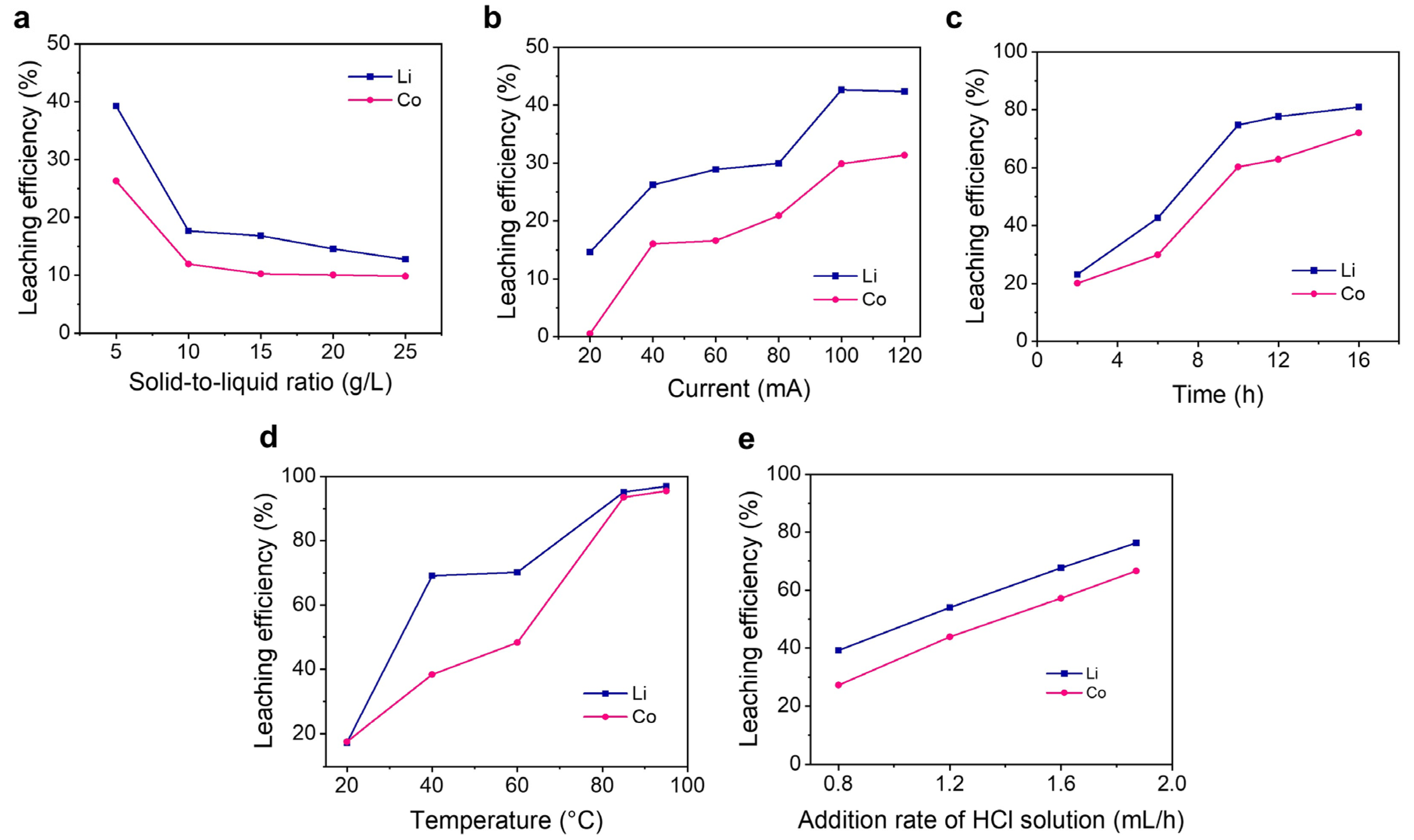
3.3. Effects of Parameters on Leaching Efficiencies of Li and Co

To understand the process and optimise the performance, a series of aqueous NaCl electrolysis experiments were conducted to investigate the effects of a multitude of factors (e.g., solid-to-liquid ratio, applied current, duration, temperature, and HCl solution addition rate) on the leaching efficiencies of Li and Co.

3.3.1. Effect of Solid-to-Liquid Ratio

Figure 3a shows the effect of solid-to-liquid ratio on the leaching efficiencies of Li and Co. The experiments were conducted at 85 °C for 6 h with a current of 100 mA. First, 2 M HCl was steadily injected into the anode chamber of the electrolyser at a rate of 0.93 mL/h using a micro-syringe pump. As the solid-to-liquid ratio decreased, the leaching efficiencies of Li and Co increased accordingly. Notably, when the solid-to-liquid ratio was 5 g/L, the leaching efficiencies after 6 h reached 39.2% for Li and 26.3% for Co, which were significantly greater than those obtained with higher solid-to-liquid ratios. Reducing the solid-to-liquid ratio essentially optimises the three-dimensional mass transfer environment of the reaction system. When the solid phase proportion is too high, solid particles form a relatively dense packing, resulting in more difficult acid penetration. Under these circumstances, the probability for H⁺ to contact the LiCoO2 is significantly reduced, while the local concentration of dissolved products rapidly increases [38], which in turn inhibits the continuous release of metal ions. In contrast, under low solid-to-liquid ratio conditions, the ample liquid phase space allows acid to contact the LiCoO2 [39,40]. For the layered structure of LiCoO2, excessive acid solution can continuously flush out the leached Li⁺ and Co2+. Meanwhile, the reduction and dissolution of Co3⁺ benefit from the adequate supply of Cl⁻ serving as both reductant and ligand, overcoming the confinement of the Co–O octahedron in the lattice and forming cobalt (II) chloride complexes, such as [CoCl4]2⁻, in the aqueous electrolyte [41].

3.3.2. Effects of Applied Current and Duration

The leaching efficiencies of Li and Co under different current conditions (20, 40, 60, 80, 100, 120 mA) are shown in Figure 3b, with a temperature of 85 °C, a solid-to-liquid ratio of 5 g/L, an HCl addition rate of 0.93 mL/h, and an electrolysis duration of 6 h. It is evident that as the current increased, the leaching efficiencies also increased accordingly. When the current was increased from 20 mA to 100 mA, the leaching efficiency of Li increased from 14.6% to 42.6%, and that of Co increased from 0.56% to 29.9%. An increase in current essentially provided more H+ to the anode chamber of the reaction system, promoting the leaching of Li and Co. Note that, as the current rose from 20 mA to 100 mA, the steady-state electrolysis voltage increased from 2.1 V to 2.8 V (Figure S4), smaller than that required in the neutral water electrolysis [15,23,24]. Because the improvement in leaching efficiency was limited as the current rose from 100 to 120 mA, we selected 100 mA as the electrolysis current condition for the subsequent experiments unless stated otherwise. Figure 3c presents the leaching efficiencies of Li and Co at different electrolysis durations (2, 6, 10, 12, and 16 h) with 2 M HCl solution addition rate of 0.93 mL/h. As the electrolysis duration extended, the leaching efficiencies of Li and Co also improved. After a relatively fast stage, the increase in leaching efficiency slowed down as the reaction proceeded for 10 h.

3.3.3. Effect of Temperature

Figure 3d shows the leaching efficiencies of Li and Co at different temperatures (20, 40, 60, 85, and 95 °C) under a solid-to-liquid ratio of 5 g/L, 100 mA, and a 2M HCl addition rate of 0.93 mL/h for 20 h. The leaching efficiencies of both Li and Co increased with the temperature. Higher temperatures enhanced the mobility of ions, promoting the dissociation of the material’s crystal structure and thus intensifying the leaching kinetics. The ionisation of HCl was an endothermic process. Higher temperatures enhanced HCl ionisation, supplying more H⁺ ions that boosted the leaching [42]. Due to the limited increase in leaching efficiency as the temperature rose from 85 °C to 95 °C, we selected 85 °C as the temperature condition for the subsequent experiments unless stated otherwise.

3.3.4. Effect of the HCl Addition Rate

Figure 3e shows the effect of the addition rate of 2 M HCl on the leaching efficiencies of Li and Co. Under the conditions of a solid-to-liquid ratio of 5 g/L, a current of 100 mA, a temperature of 85 °C, and a reaction time of 6 h, the leaching rates of Li and Co were measured for different HCl addition rates. Apparently, the leaching efficiencies of both Li and Co increased with the increasing HCl addition rate. An elevated acid concentration significantly boosted the H+ and Cl concentrations in the anode chamber, which not only enhanced the displacement ability of H+ for Li+ but also favoured the leaching of Co. Based on the Fick’s first law, as HCl was continuously consumed at the solid–liquid interface, an increase in HCl concentration lead to an increase in diffusion flux, thereby accelerating the diffusion of protons [43]. By adjusting the HCl addition rate, the Co leaching efficiency after 6 h was improved from 27.3% to 66.7%. Based on the electrolysis current, assuming 100% selectivity of the Cl2 evolution reaction, the rate of adding 2 M hydrochloric acid per unit time was calculated to be ~1.87 mL/h. In actual experiments, the rate of adding 2 M HCl solution was slightly adjusted to 1.85 mL/h.
By systematically varying the variables and measuring their effects, the favourable combination of conditions was determined to be 5 g/L solid-to-liquid ratio, 100 mA current, 85 °C temperature, and 1.85 mL/h addition rate of 2 M HCl solution. In an experiment under such optimal conditions, a high leaching efficiency of the solid LiCoO2 (98.8% Li and 95.8% Co) was achieved within 13.5 h. Figure S5 shows the digital photographs of the setup taken at the 1st hour and the 12th hour.

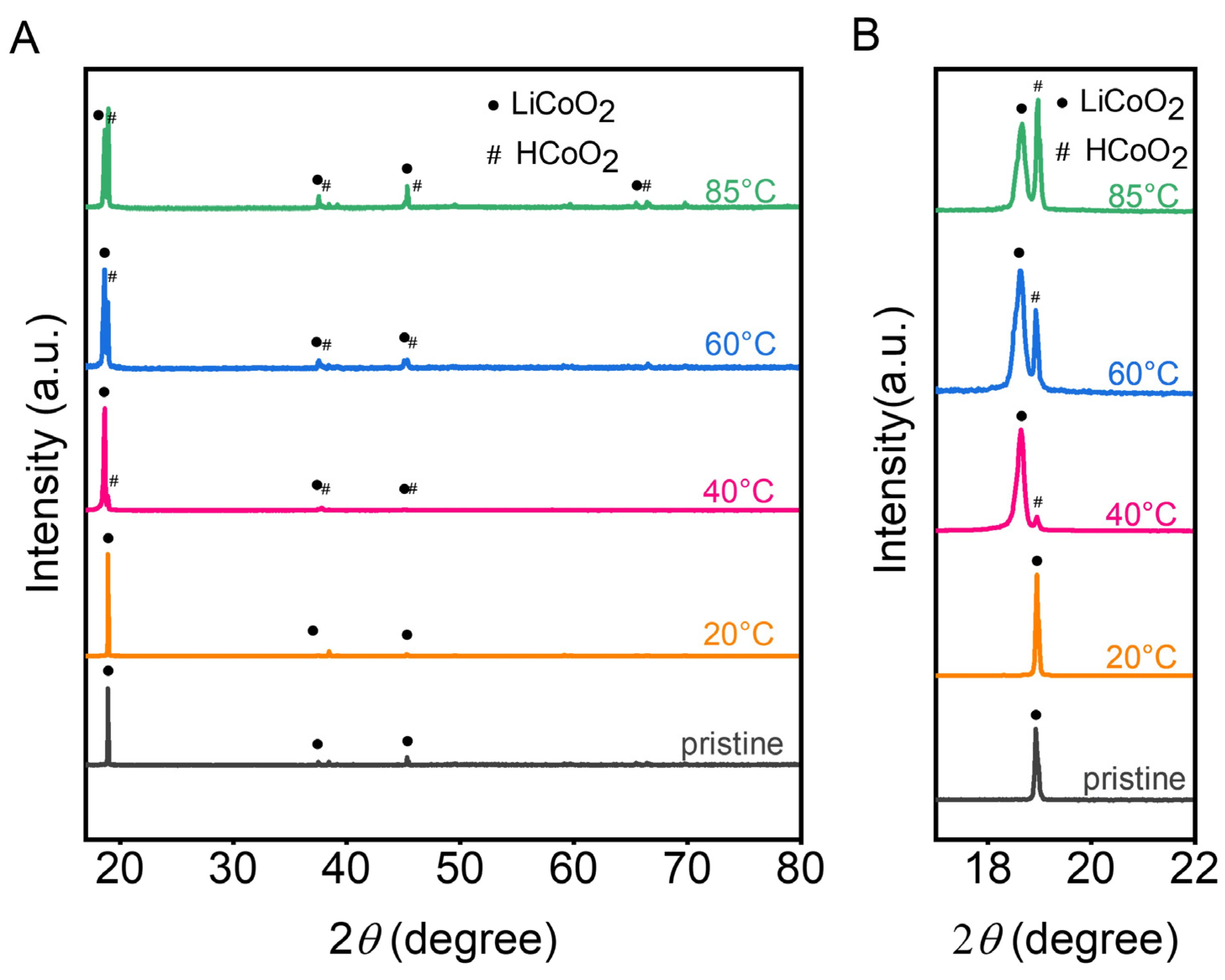
3.4. Materials Characterisation

3.4.1. The Residue Powders in the Anode Chambers

LiCoO2 possesses a layered hexagonal crystal structure in which the CoO2 layers and the Li layers are alternately arranged. In this structure, Co and O form an octahedral structure, and Li ions can be considered to be located in the interstices between these octahedral layers. Due to this specific structural arrangement, Li+ can be relatively easily removed from the structure. SEM images and EDS mapping results (Figure S6) show the changes in the powders before and after the leaching. The pristine LiCoO2 powders exhibited smooth surfaces and uniform distribution of Co and O elements (Figure S6a–c). After leaching, the morphology of the residual powder changed significantly, with evident cracks appearing on the surface (Figure S6d). EDS mapping results showed that the distribution of Co and O elements was still uniform in the residual particles, except that the signal intensity in the areas of cracks was weakened. X-ray diffraction (XRD) analysis was used to characterise the residual powders after leaching at different temperatures (20, 40, 60, and 85 °C), as shown in Figure 4. The XRD patterns show that the residual powders retained the α-NaFeO2-type structure, with the main diffraction peaks attributed to the (003) planes; in other words, all residual powders retained the layered structure in the c-axis direction [44,45,46]. After the leaching, the originally separable pairs of peaks, (006) and (012), as well as (018) and (110), merged almost into one peak and no longer remained distinctly separated [44,47]. Compared with the XRD pattern of the pristine sample, the (003) diffraction peak of the residual powders shifts to lower diffraction angles, revealing an increase in the interlayer spacing of the Co–O octahedra. This lattice expansion along the c-axis direction was attributed to the leaching of lithium between the two Co–O octahedral layers, leading to an enhancement of the electrostatic repulsion between oxygen ions [46].
As shown in Figure 4, in the XRD patterns of the samples after acid leaching, a companion peak was observed on the high diffraction angle side of the (003) main peak, with a slightly higher 2θ value, indicating a small amount of exchange between H+ and Li+ ions [48,49]. This was related to the conversion of LiCoO2 to HCoO2 during acid leaching [24,50]. At 20 °C, the small amount of exchange between H and Li results in the overlap of the secondary peak with the main peak. At 40, 60, and 85 °C, the increased exchange of H+ and Li+ ions led to an increase in the separation between the secondary peak and the main peak due to the extraction of more Li from the lattice. As the temperature increased from 20 to 85 °C, the (003) diffraction peak of HCoO2 gradually intensified, confirming the positive correlation between the extent of H⁺–Li⁺ exchange and the temperature.
The residue powders in the anode chamber after different electrolysis times (5, 10, 12, 16, and 20 h) were also characterized with XRD, as shown in Figure S7. Similarly, two distinct peaks related to the (003) crystal planes were observed at around 19°. As the leaching time increased, the intensity of the diffraction peak for HCoO2 also increased, indicating an increased degree of ion exchange between H⁺ and Li⁺ with longer leaching times.
Raman analysis of the solid powders before and after leaching revealed different peaks (Figure S8). After leaching, the characteristic peaks at ~477 cm⁻1 and ~594 cm⁻1 corresponded to the LiCoO2. Additionally, new peaks appeared at 575 cm⁻1 and 689 cm⁻1, which were attributed to Co3O4 formed by the decomposition reaction of LiCoO2 [19,51]. XPS results showed changes in the LiCoO2 powders before and after leaching (Figure S9). The O 1s spectrum of the pristine LiCoO2 powders displayed two major peaks, one at 529.4 eV belonging to O2⁻ anions in the crystal structure, and another at 531.6 eV corresponding to adsorbed oxygen species on the surface. After leaching, a new peak appears at ~531 eV, indicating a higher degree of oxidation, similar to the O⁻ in peroxides, suggesting that O2⁻ ions in the lattice participated in the charge compensation during the reduction of Co3+ in the leaching process [24]. However, the intensity of this peak was relatively weak based on the curve fitting, so its contribution to the Co3+ reduction might be quite small.

3.4.2. Precipitates in the Cathode Chamber

HCl solution was added to the anode chamber, where it leached Li+ and Co2+ from LiCoO2. Under the influence of diffusion and convection, some of the Co2⁺ dissolved in the anode chamber was transported to the cathode chamber. During H2 evolution at the cathode, OH⁻ was generated to create an alkaline environment in the cathode chamber. Previous studies have shown that Co2⁺ begins to precipitate when the pH reaches 6.7 and precipitates completely at a pH of 9.4. The high pH value in the cathode chamber favoured the precipitation of Co2⁺ in both the cathode chamber and the cross tube. After a 13.5 h electrolysis experiment under the conditions of 5 g/L solid-to-liquid ratio, 100 mA current, 85 °C temperature, and 2 M HCl addition rate of 1.85 mL/h, the solutions in the anode and cathode chambers were separated using pipettes. The precipitates formed in the cathode chamber were collected by centrifugation, rinsed, and then dried.
Scanning electron microscope (SEM) images of the precipitates on conductive carbon cloth revealed that the precipitates had a flocculent appearance (Figure 5a). The XRD pattern of the precipitate shows the characteristic peak of Co(OH)2, suggesting low crystallinity (Figure S10). The XPS survey spectrum (Figure 5b) showed that the precipitate was mainly composed of cobalt, oxygen, and carbon. The minor signal at ~153 eV was likely attributed to Si 2s in Na2SiO3 trace impurity formed by the reaction between the glass container and the NaOH in the electrolyte [52]. The high-resolution Co 2p spectrum (Figure 5c) exhibited characteristic peaks at 781 eV and 796.8 eV, which matched the orbital splitting characteristics of Co(OH)2 and corresponded to the spin–orbit peaks of Co 2p3/2 and Co 2p1/2, respectively [53]. During electrolysis at a current of 100 mA, 548.4 g Co(OH)2 can be recovered per kWh of electricity. Notably, based on the precipitates directly collected from the cathode chamber after 13 h of electrolysis, the direct recovery rate of cobalt was approximately 56.46%, since not all dissolved Co2⁺ was transported to the cathode chamber and precipitated during electrolysis. However, by mixing the solution from the cathode chamber with that from the anode chamber, the remaining Co2⁺ in the anode chamber solution was precipitated, resulting in a total recovery rate of Co2⁺ reaching 99.85%. After the reaction, the system retains a high pH gradient. The anode chamber solution is highly acidic and contains significant amounts of Na+, Cl, and other metal ions (Li+ and Co2+). In contrast, the cathode chamber solution is strongly alkaline, containing significant amounts of Na+ and Cl, and reacts with the transition metal ions (other than Li+) migrating from the anode to form precipitates. In this study, the solutions from the anode and cathode chambers were mixed after each experiment. These solutions can be reused as electrolytes for the next leaching cycle after removing any precipitates and adjusting the pH, thereby minimising wastewater generation.

3.4.3. The DSA in the Anode Chamber

To evaluate the stability of the DSA electrode (RuO2/IrO2-coated Ti mesh) used in the anode chamber, a 13 h electrolysis experiment was performed under the conditions of 5 g/L solid-to-liquid ratio, 100 mA current, 85 °C and 2 M HCl addition rate of 1.85 mL/h. The surface of the DSA electrode was characterised with SEM and EDS before and after the electrolysis experiment (Figures S11 and S12). Based on the surface morphology and the homogeneity of the elemental distribution, the electrode did not exhibit obvious corrosion, likely due to the relatively short testing duration. The relative stability of the DSA electrode was further supported by the linear sweep voltammetry scan at different times in another electrolysis experiment (Figure S13), where the LSV curves above the onset potential of the Cl2 evolution reaction were almost overlapping at the beginning and the 24th hour. In fact, we have observed that, despite hundreds of hours of accumulated electrolysis experiments, the DSA electrode was never replaced and yet still performed relatively well.
Nevertheless, it should be noted that DSA electrode may suffer from degradation in microstructure and composition if tested for a much more extended period. Previous works have reported various mechanisms for the degradation of the DSA electrode. For example, the Cl has a low diffusion barrier, so it may penetrate the passivation layer of the electrodes and cause corrosion [54]. Due to the high contents of H+ and Cl in the anode chamber, the formation of soluble Ru species may occur, affecting the activity and stability of the chlorine evolution reaction [55]. In addition, the evolution of gas bubbles may cause the gradual removal of the compact mixed metal oxides surface [56]. Therefore, the long-term stability of the DSA electrode in the H-cell needs to be further evaluated in future work.

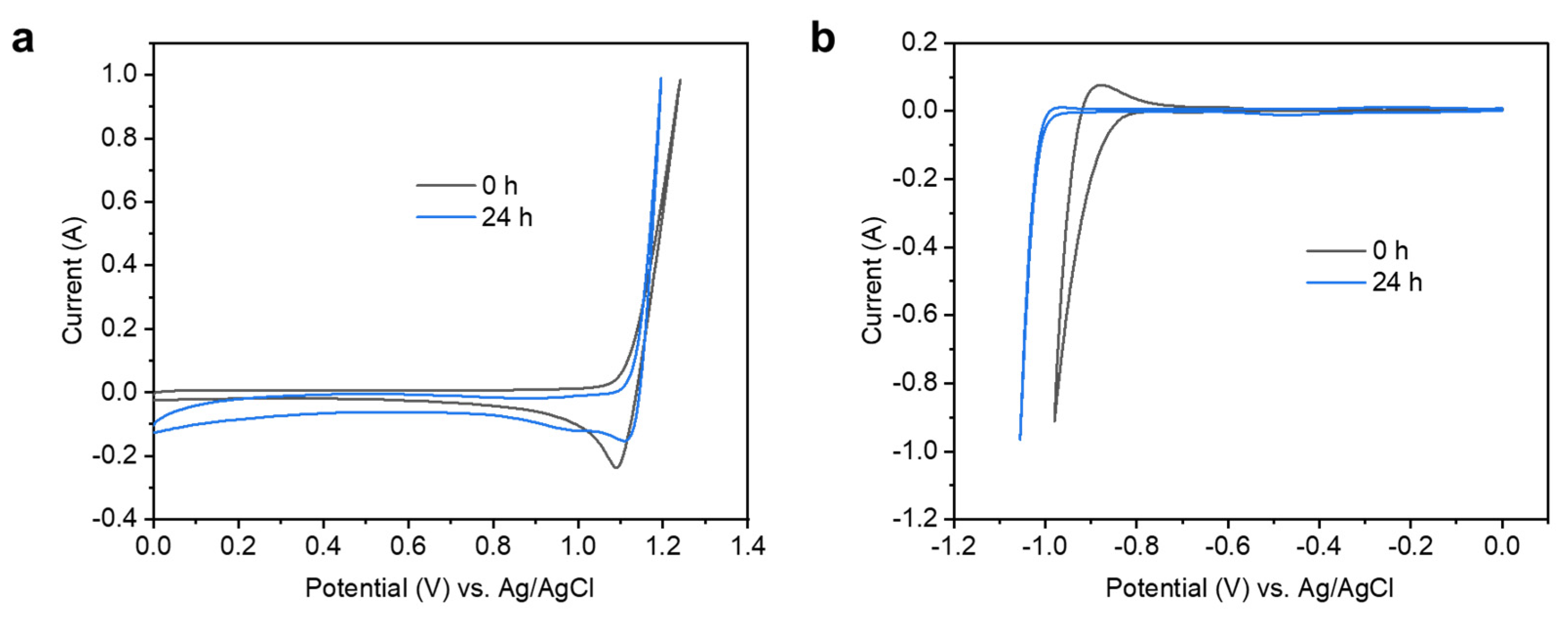
3.5. Electrochemical Characterisation of the Electrolytic Cell

In the H-shaped electrolytic cell, each of the anode chamber and the cathode chamber contained 150 mL of 5 M NaCl electrolyte. Pristine LiCoO2 powders were loaded into the anode chamber at a solid-to-liquid ratio of 5 g/L. During the electrolysis process, a current of 100 mA was applied, and 2 M HCl solution was continuously injected into the anode chamber at a rate of 1.85 mL/h. The test was conducted at 50 °C, which was below the recommended upper temperature limit (60 °C) for the Ag/AgCl reference electrode. Cyclic voltammetry (CV) scanning of the anode showed an onset potential for Cl2 evolution (Equation (2)) at around 1.12 V (Figure 6a). After 24 h of electrolysis, the onset potential for Cl2 evolution remained essentially unchanged.
CV scanning of the cathode revealed an onset potential for hydrogen evolution (Equation (3)) at –0.88 V (Figure 6b). Notably, after 24 h of electrolysis, the onset potential for H2 evolution shifted negatively to –0.96 V, which was closely related to the Nernst potential shift caused by the increase in pH in the cathode region. Previous pH monitoring data (Figure 2c) showed that the alkalinity of the electrolyte in the cathode chamber rapidly increased within the first 2 h of electrolysis and then reached a relatively stable value with significantly reduced fluctuations.
The initial CV curve for the anode (Figure 6a) showed a characteristic reduction peak at around 1.1 V during the negative scan, attributable to the reduction reaction of the adsorbed Cl2, which persisted also after 24 h of reaction. The initial CV curve for the cathode (Figure 6b) exhibited a broad characteristic oxidation peak at around –0.9 V during the positive scan, attributed to the redox reaction of adsorbed H2, which was no longer evident after 24 h of reaction, indicating weakened H2 adsorption over time.

3.6. Recycling of LiNi0.5Co0.2Mn0.3O2 (NCM523)

Since NCM523 is also a widely used positive electrode material of LIBs, a similar H-shaped dual-chamber electrolytic cell as shown in Figure 1 was constructed for recycling it. The chlorine evolution reaction occurred at the anode, and the HCl solution was continuously added to the anode chamber (Equation (6)), creating a strongly acidic leaching environment to promote the dissolution of the ternary cathode material. At the cathode, the hydrogen evolution reaction generated OH⁻ (Equations (7)–(9)), leading to the precipitation of transition metal ions. Compared with the Co(OH)2 and Ni(OH)2, Mn(OH)2 was prone to auto-oxidation in the air environment, gradually transforming into brownish MnOOH (Equation (10)), a process that could even be triggered by trace amounts of dissolved oxygen in the solution. It is noted that the HClO was generated by Cl2 dissolution despite the high HCl concentration in the anode chamber, and could be transported to the cathode chamber to oxidise the precipitates, especially the Mn(OH)2. Yet, this contribution was minor considering the easy reduction of ClO⁻ at the cathode (ClO⁻ + H2O + 2e⁻ → Cl⁻ + 2OH⁻) [57].
LiNi0.5Co0.2Mn0.3O2 + 2HCl →
LiCl + 0.5NiCl2 + 0.2CoCl2 + 0.3MnCl2 + 0.5Cl2 + H2O
Ni2+ + 2OH → Ni(OH)2
Co2+ + 2OH → Co(OH)2
Mn2+ + 2OH → Mn(OH)2
2Mn(OH)2 + 0.5O2 → 2MnOOH + H2O
The leaching efficiencies of metal ions from NCM523 were systematically investigated under various leaching conditions, including temperature, current, time, solid-to-liquid ratio, and rate of adding 2 M HCl solution. Figure 7 shows that the trend of the leaching efficiencies of the four metals (Li, Ni, Co, and Mn) in NCM523 was, in general, similar to that of LiCoO2, with low solid-to-liquid ratio, high current, high temperature, and high acid concentration favouring the improvement of leaching efficiencies. Under more favourable leaching conditions (a solid-to-liquid ratio of 5 g/L, a constant current of 100 mA, a 2 M HCl addition rate of 1.85 mL/h, and electrolysis at 85 °C for 24 h), leaching efficiencies of 99.9% Li, 99.9% Ni, 99.8% Co, and 96.7% Mn were achieved.
Figure 7d depicts the leaching efficiencies of Li, Ni, Co, and Mn in NCM523 in electrolysis experiments at different temperatures (30, 45, 65, 85, 95 °C) with a solid-to-liquid ratio of 5 g/L, constant current of 100 mA, 2 M HCl addition rate of 1.85 mL/h, and reaction duration of 24 h. Specifically, the leaching behaviour of Li exhibited a positive correlation with temperature similar to that in LiCoO2; the leaching efficiency of Li was 36.2% at 30 °C, jumped to 95.6% at 45 °C, and reached 99.9% at 65 °C. The increase of leaching efficiency as the temperature rose from 85 °C to 95 °C was not obvious. Ni and Co exhibited different leaching characteristics. NCM523 had a layered structure similar to LiCoO2. However, the mixed valence distribution of Ni2⁺/Ni3⁺ in NCM523 resulted in a lower Ni–O bond dissociation energy than the Co3⁺–O bond [58], which thereby generally caused Ni to leach slightly preferentially. The leaching efficiency of Mn (89.6% at 65 °C) was lower than that of Ni and Co, which was closely related to its stabilising role in the layered structure. Compared to the Ni–O or Co–O bonds, the higher bond energy of Mn–O bonds significantly inhibited the release of Mn2⁺ to the solution. To address the issue of Mn’s slow leaching kinetics in ternary materials, future efforts may involve further treatment of the residues by H2 reduction roasting at elevated temperatures (e.g., 850 °C) [15] or introducing coordination-enhanced strategies, such as using optimised deep eutectic solvents [59]. The XRD patterns of the anode residue at various temperatures (30, 45, 65, 85 °C) reveal a minor diffraction peak emerging in the high-angle region of the (003) crystal plane (Figure 8a). This peak is attributed to the ion exchange between H⁺ and Li⁺ during leaching, leading to the formation of HNixCoyMnzO2. As the temperature increases, the intensity of this peak rises, indicating that higher temperatures accelerate ion mobility in both solutions and solids, thereby speeding up the H⁺/Li⁺ exchange and enhancing the formation of the HNixCoyMnzO2 phase. With increasing temperature, the (006)/(012) and (018)/(110) peak groups became less distinct after leaching, suggesting that the layered structure loses its order. This is likely due to the similar radii of Ni2⁺ and Li⁺, which causes a certain degree of intermixing between Li⁺ and Ni2⁺ during the leaching process [49]. After 65 °C, with the near-complete leaching of Li, Ni, and Co elements, the characteristic peaks of NCM gradually disappeared, and the remaining solid was mostly MnO2 [60]. This finding aligned with the temperature dependence of the leaching efficiency (Figure 7d).
The precipitates collected from the cathode chamber of the electrolysis experiment under the conditions of 5 g/L solid-to-liquid ratio, 100 mA current, 85 °C and 2 M HCl addition rate of 1.85 mL/h for 24 h were also characterised. XRD analysis shows the existence of wide diffraction peaks, indicating low crystallinity (Figure S14). The SEM image shows the irregular morphology (Figure S15). In the Ni 2p XPS spectrum (Figure 8b), the peak positions of 2p3/2 and 2p1/2 (856.3 and 873.9 eV) indicated the formation of Ni(OH)2 according to the XPS database of AvantageTM software (v5.9931). In the Co 2p XPS spectrum (Figure 8c), the difference of ~15.8 eV between the 2p3/2 and 2p1/2 peaks confirmed the presence of the Co(OH)2 phase. In the Mn 3s XPS spectrum (Figure 8d), the peak splitting (ΔBE) of ~5.8 eV indicated that the precipitates contained a mixture of Mn2+ and Mn3+ [61]. The SEM images and EDS mapping of Ni, Co, and Mn in NCM523 particles before (Figure S16a–d) and after (Figure S16e–h) the leaching showed that the NCM523 particles collapsed from a spherical shape into pieces.

3.7. Discussion on Challenges to Address for Large-Scale Applications

Despite promising laboratory-scale results, several challenges must be addressed for large-scale implementation. The durability of electrolysis components, especially the DSA anode, may require improvement. Operating under acidic (pH < 2) and high-temperature conditions (85 °C) for extended periods would accelerate the electrode corrosion and cause performance degradation. To address this, developing corrosion-resistant coatings, such as IrO2-Ta2O5-based composites [62], or exploring alternative anode materials could be effective solutions. In addition to improving component durability, the transition from batch-mode experiments to continuous-flow operation is necessary for handling large volumes of spent battery materials. Modular H-type electrolysers equipped with automated HCl injection and real-time pH monitoring could enhance scalability and system integration. Furthermore, the method’s applicability to a variety of cathode materials, including high-nickel NCM (e.g., NCM811), needs to be validated. Finally, the economic viability of the process must be assessed. Although the HCl regeneration reduces reagent costs, the initial capital investment for electrolysis infrastructure and energy demands could offset these savings. Conducting life-cycle assessments (LCA) and techno-economic analyses is crucial to quantify the environmental benefits and operational costs compared to existing pyrometallurgical–hydrometallurgical hybrid processes. Moreover, HCl is both toxic and corrosive, hydrogen is flammable, and chlorine is corrosive. These gases must be strictly managed during large-scale production to ensure safety. Additionally, the strong acid and alkali environments, along with corrosive gases, may present significant safety challenges to the durability of pipelines and equipment.

4. Conclusions

In summary, this work presents a proof-of-concept demonstration of a new method for recovering the positive cathode materials of Li-ion batteries. It leverages the electrolysis of aqueous NaCl solution and the addition of the HCl generated to the anode chamber. A large pH gradient was established across the anode chamber (pH = ~0.5) and the cathode chamber (pH = ~13) in the H-cell. This enables simultaneous leaching in the anode chamber and precipitation in the cathode chamber. In principle, the HCl can be generated through the reaction of H2 and Cl2, products of the NaCl electrolysis, establishing a chlorine cycle. This method showed promise in mitigating the need for external acid and base and reducing wastewater generation. Under the favoured conditions (5 g/L solid-to-liquid ratio, 100 mA current, 85 °C temperature, and an addition rate of 2 M HCl at 1.85 mL/h), 98.8% Li and 95.8% Co leaching efficiencies after 13.5 h of electrolysis experiment for LCO were achieved. Under similar conditions, 99.9% Li, 99.9% Ni, 99.8% Co, and 96.7% Mn leaching efficiencies were achieved after 24 h of electrolysis experiment for NCM.
Compared with traditional recycling processes, this method not only significantly enhances the leaching efficiency of metals but also achieves resource generation and recycling via electrochemical means. This proposed method represents an important advancement in the field of spent LIB recycling and offers a solution that aligns with the sustainable development principles. The use of industrial-grade electrodes and DSA anodes aligns with existing chlor-alkali infrastructure, minimising retrofitting costs for scalable deployment. High recovery rates combined with reduced chemical consumption position this approach as a competitive candidate for industrial adoption. More research and development are still required to further improve this process for large-scale applications in the future.

Supplementary Materials

The following supporting information can be downloaded at: https://www.mdpi.com/article/10.3390/pr13051525/s1, Note S1: Quantification of Cl2 using methyl orange spectrophotometry; Figure S1: (a) Digital photograph of the standard solutions with the equivalent chlorine concentrations ranging from 0 (left) to 700 μg/L (right) as labelled on the 10 mL transparent test tubes. With the increase in the equivalent chlorine concentration, the pink colour of the solution gradually decreases. (b) The absorbance of each standard solution vs. the equivalent chlorine concentration (µg/L). The data were fitted to a linear line with the equation of y = –0.00058x + 0.5106 and the coefficient of determination (r2) value of 0.9911; Figure S2: GC measurement of the anode chamber outlet gas (a) after the air in the anode chamber and gas lines was purged with N2 and (b) during 100 mA electrolysis of 5 M NaCl solution at 85 °C and 1.87 mL/h HCl addition rate. A small peak for O2 at the retention time of 10.225 min was identified in the measurements after the system stabilises. Two small peaks near 3.025 min and 10.037 min retention times, respectively, were due to the GC instrumentation. The small peak of H₂ at a retention time of 2.335 min is due to microbubbles from the cathode chamber entering the anode chamber during pressure balance adjustment. Note S2: Deterioration of filter papers during aqueous NaCl electrolysis; Figure S3: The structural collapse of the filter papers. Digital photographs of (a) the H-cell, (b) the anode chamber, (c) and the cathode chamber after removing their top lids; Figure S4: Voltage change over time under the conditions of 5 g/L LCO solid-to-liquid ratio, 100 mA current, 85 °C temperature, and a 2 M HCl addition rate of 0.93 mL/h for 6 h; Figure S5: Digital photographs of the setup for leaching LCO in the anode chamber (left side of the H-cell) and precipitating Co(OH)2 in the cathode chamber (right side of the H-cell) taken at different times: (a) 1 h, (b) 12 h. Experimental conditions include 5 g/L solid-liquid ratio, 100 mA current, 85 °C temperature, 1.85 mL/h addition rate of 2 M HCl solution; Figure S6: SEM images and EDS mapping results of the O and Co elements in the LiCoO2 powders (ac) before the leaching and in the residue powders (df) after the leaching; Figure S7: (A) XRD patterns of the pristine waste powders and the residue powders after leaching for 5, 10, 12, 16 and 20 h in the anode chambers of the electrolysers under the conditions of 5 g/L solid-to-liquid ratio, 100 mA current, 85 °C temperature, and a 2 M HCl addition rate of 1.85 mL/h. (B) Magnified XRD pattern from 2θ = 17° to 22°. The diffraction peaks are indexed using data from the standard PDF cards for LiCoO2 (No. 01–075-3201) and HCoO2 (No. 04–012-5033).; Figure S8: Raman spectra of (a) the pristine LCO powders and (b) the residue powders after 13.5 h leaching in the anode chamber of an electrolyser under the conditions of 5 g/L solid-to-liquid ratio, 100 mA current, 85 °C temperature, and 2 M HCl addition rate of 1.85 mL/h; Figure S9: The O 1s XPS results of the pristine LiCoO2 powders before leaching and the residue powders after leaching for 6, 12, and 16 h, respectively, in the anode chambers of the electrolysers under the conditions of 5 g/L solid-to-liquid ratio, 100 mA current, 85 °C temperature, and a 2 M HCl addition rate of 1.85 mL/h; Figure S10: The XRD pattern of the hydroxide precipitates collected from the cathode chamber after the LCO electrolysis experiment under the conditions of 5 g/L solid-to-liquid ratio, 100 mA current, 85 °C temperature, and 2 M HCl addition rate of 1.85 mL/h for 13.5 h; Figure S11: (a) SEM and (bd) EDS mapping results of DSA electrode before the electrolysis under the conditions of 5 g/L solid-to-liquid ratio, 100 mA current, 85 °C temperature, and a 2 M HCl addition rate of 1.85 mL/h for 13 h; Figure S12: SEM (a) and EDS (bd) test of DSA electrode after the electrolysis under the conditions of 5 g/L solid-to-liquid ratio, 100 mA current, 85 °C temperature, and a 2 M HCl addition rate of 1.85 mL/h for 13 h; Figure S13: Linear sweep voltammetry (LSV) scans for the DSA anode relative to the Ag/AgCl reference electrode measured at different times of an electrolysis experiment under the conditions of 5 g/L solid-to-liquid ratio, 100 mA current, 50 °C temperature, and addition of 2 M HCl solution at a rate of 1.85 mL/h. Scan rate: 50 mV/s. The two LSV curves were almost overlapping at potentials above the onset potential for chlorine evolution reaction (~1.1 V); Figure S14: XRD pattern of the hydroxide precipitates after the NCM electrolysis experiment under the conditions of 5 g/L solid-to-liquid ratio, 100 mA current, 85 °C temperature, and 2 M HCl addition rate of 1.85 mL/h for 24 h; Figure S15: (a,b) SEM image of the precipitates collected from the cathode chamber after the NCM electrolysis experiment under the conditions of 5 g/L solid-to-liquid ratio, 100 mA current, 85 °C temperature, and 2 M HCl addition rate of 1.85 mL/h for 24 h; Figure S16: (a,g) SEM and (bd,fh) EDS mapping of Ni, Co, and Mn of NCM523 particle (af) before and (gh) after the leaching in the electrolysis experiment under the conditions of 5 g/L solid-to-liquid ratio, 100 mA current, 85 °C temperature, and a 2 M HCl addition rate of 1.85 mL/h for 14 h. References [33,63] are cited in the supplementary materials.

Author Contributions

Y.C.: data curation, formal analysis, investigation, visualisation, writing—original draft; X.G.: conceptualisation, funding acquisition, project administration, resources, supervision, writing—review and editing. All authors have read and agreed to the published version of the manuscript.

Funding

This material is based on work supported by ShanghaiTech University. Part of the characterisation was performed at the Analytical Instrumentation Centre (Grant No.: SPST-AIC10112914) and the Centre for High-resolution Electron Microscopy (CħEM, Grant No.: EM02161943) at ShanghaiTech University.

Data Availability Statement

The original contributions presented in this study are included in the article. Further inquiries can be directed to the corresponding author.

Acknowledgments

The authors acknowledge the financial support from ShanghaiTech University. Y.C. thanks Jiayin Zhou and Yuxi Zheng for the SEM and EDS characterisation and the helpful discussion.

Conflicts of Interest

There are no conflicts of interest to declare.

References

  1. Tarascon, J.M.; Armand, M. Issues and challenges facing rechargeable lithium batteries. Nature 2001, 414, 359–367. [Google Scholar] [CrossRef] [PubMed]
  2. Goodenough, J.B.; Kim, Y. Challenges for Rechargeable Li Batteries. Chem. Mater. 2010, 22, 587–603. [Google Scholar] [CrossRef]
  3. Kebede, A.A.; Kalogiannis, T.; Van Mierlo, J.; Berecibar, M. A comprehensive review of stationary energy storage devices for large scale renewable energy sources grid integration. Renew. Sustain. Energy Rev. 2022, 159, 112213. [Google Scholar] [CrossRef]
  4. Velázquez-Martínez, O.; Valio, J.; Santasalo-Aarnio, A.; Reuter, M.; Serna-Guerrero, R. A Critical Review of Lithium-Ion Battery Recycling Processes from a Circular Economy Perspective. Batteries 2019, 5, 68. [Google Scholar] [CrossRef]
  5. Li, H.; Berbille, A.; Zhao, X.; Wang, Z.; Tang, W.; Wang, Z.L. A contact-electro-catalytic cathode recycling method for spent lithium-ion batteries. Nat. Energy 2023, 8, 1137–1144. [Google Scholar] [CrossRef]
  6. Sederholm, J.G.; Li, L.; Liu, Z.; Lan, K.-W.; Cho, E.J.; Gurumukhi, Y.; Dipto, M.J.; Ahmari, A.; Yu, J.; Haynes, M.; et al. Emerging Trends and Future Opportunities for Battery Recycling. ACS Energy Lett. 2025, 10, 107–119. [Google Scholar] [CrossRef]
  7. Fu, Y.; He, Y.; Li, J.; Qu, L.; Yang, Y.; Guo, X.; Xie, W. Improved hydrometallurgical extraction of valuable metals from spent lithium-ion batteries via a closed-loop process. J. Alloys Compd. 2020, 847, 156489. [Google Scholar] [CrossRef]
  8. Gao, W.; Song, J.; Cao, H.; Lin, X.; Zhang, X.; Zheng, X.; Zhang, Y.; Sun, Z. Selective recovery of valuable metals from spent lithium-ion batteries—Process development and kinetics evaluation. J. Clean. Prod. 2018, 178, 833–845. [Google Scholar] [CrossRef]
  9. Assefi, M.; Maroufi, S.; Yamauchi, Y.; Sahajwalla, V. Pyrometallurgical recycling of Li-ion, Ni–Cd and Ni–MH batteries: A minireview. Curr. Opin. Green Sustain. Chem. 2020, 24, 26–31. [Google Scholar] [CrossRef]
  10. Havlík, T. Chapter 16—The Current State and Prospects of Hydrometallurgical Processes. In Hydrometallurgy; Havlík, T., Ed.; Woodhead Publishing: Sawston, UK, 2008; pp. 479–534. [Google Scholar]
  11. Minimol, M.; Shetty, V.; Saidutta, M.B. Biohydrometallurgical Methods and the Processes Involved in the Bioleaching of WEEE; Elsevier: Boston, MA, USA, 2021; pp. 89–107. [Google Scholar]
  12. Larouche, F.; Tedjar, F.; Amouzegar, K.; Houlachi, G.; Bouchard, P.; Demopoulos, G.P.; Zaghib, K. Progress and Status of Hydrometallurgical and Direct Recycling of Li-Ion Batteries and Beyond. Materials 2020, 13, 801. [Google Scholar] [CrossRef]
  13. Vieceli, N.; Benjamasutin, P.; Promphan, R.; Hellström, P.; Paulsson, M.; Petranikova, M. Recycling of Lithium-Ion Batteries: Effect of Hydrogen Peroxide and a Dosing Method on the Leaching of LCO, NMC Oxides, and Industrial Black Mass. ACS Sustain. Chem. Eng. 2023, 11, 9662–9673. [Google Scholar] [CrossRef]
  14. Guimarães, L.F.; Botelho Junior, A.B.; Espinosa, D.C.R. Sulfuric acid leaching of metals from waste Li-ion batteries without using reducing agent. Miner. Eng. 2022, 183, 107597. [Google Scholar] [CrossRef]
  15. Zhou, J.; Ni, J.; Guan, X. The critical role of H2 reduction roasting for enhancing the recycling of spent Li-ion battery cathodes in the subsequent neutral water electrolysis. RSC Sustain. 2023, 1, 2241–2253. [Google Scholar] [CrossRef]
  16. Zhou, C.; Ni, J.; Chen, H.; Guan, X. Harnessing electrochemical pH gradient for direct air capture with hydrogen and oxygen by-products in a calcium-based loop. Sustain. Energy Fuels 2021, 5, 4355–4367. [Google Scholar] [CrossRef]
  17. Zhou, J.; Guan, X. Closed-Loop and Precipitation-Free CO2 Capture Process Enabled by Electrochemical pH Gradient. ChemSusChem 2025, 18, e202401533. [Google Scholar] [CrossRef]
  18. Drajlin, D.S.; Suarez, D.S.; Toro, N.; Gálvez, E.D.; Pinna, E.G.; Rodriguez, M.H. Comparative Study of the Dissolution of LCO in HCl Medium with and without H2O2. Metals 2022, 12, 727. [Google Scholar] [CrossRef]
  19. Freitas, M.B.J.G.; Garcia, E.M. Electrochemical recycling of cobalt from cathodes of spent lithium-ion batteries. J. Power Sources 2007, 171, 953–959. [Google Scholar] [CrossRef]
  20. Ito, H.; Manabe, A. Chapter 8—Chlor–Alkali Electrolysis. In Electrochemical Power Sources: Fundamentals, Systems, and Applications; Smolinka, T., Garche, J., Eds.; Elsevier: Boston, MA, USA, 2022; pp. 281–304. [Google Scholar]
  21. Fauvarque, J. The Chlorine Industry. Pure Appl. Chem. 1996, 68, 1713–1720. [Google Scholar] [CrossRef]
  22. Karlsson, R.K.B.; Cornell, A. Selectivity between Oxygen and Chlorine Evolution in the Chlor-Alkali and Chlorate Processes. Chem. Rev. 2016, 116, 2982–3028. [Google Scholar] [CrossRef]
  23. Zhou, J.; Bing, J.; Ni, J.; Wang, X.; Guan, X. Recycling the waste LiMn2O4 of spent Li-ion batteries by pH gradient in neutral water electrolyser. Mater. Today Sustain. 2022, 20, 100205. [Google Scholar] [CrossRef]
  24. Ni, J.; Zhou, J.; Bing, J.; Guan, X. Recycling the cathode materials of spent Li-ion batteries in a H-Shaped neutral water electrolysis cell. Sep. Purif. Technol. 2021, 278, 119485. [Google Scholar] [CrossRef]
  25. Fu, A.; Zhang, Z.; Lin, J.; Zou, Y.; Qin, C.; Xu, C.; Yan, P.; Zhou, K.; Hao, J.; Yang, X.; et al. Highly stable operation of LiCoO₂ at cut-off ≥ 4.6 V enabled by synergistic structural and interfacial manipulation. Energy Storage Mater. 2022, 46, 406–416. [Google Scholar] [CrossRef]
  26. Kumar, A.; Phillips, K.R.; Thiel, G.P.; Schröder, U.; Lienhard, J.H. Direct electrosynthesis of sodium hydroxide and hydrochloric acid from brine streams. Nat. Catal. 2019, 2, 106–113. [Google Scholar] [CrossRef]
  27. Dreyhsig, G.H.; Voßnacker, P.; Kleoff, M.; Baunis, H.; Limberg, N.; Lu, M.; Schomäcker, R.; Riedel, S. Bichloride-based ionic liquids for the merged storage, processing, and electrolysis of hydrogen chloride. Sci. Adv. 2024, 10, eadn5353. [Google Scholar] [CrossRef] [PubMed]
  28. Carvela, M.; Raschitor, A.; Rodrigo, M.A.; Lobato, J. Recent Progress in Catalysts for Hydrogen-Chlorine Regenerative Fuel Cells. Catalysts 2020, 10, 1263. [Google Scholar] [CrossRef]
  29. Wang, Y.; Li, M.; Jiang, Y.; Zhang, C.; Chang, W.; Shi, Y. Investigation of swirler effect on combustion and exergy efficiency of hydrogen/chlorine combustor based on entropy generation analysis. Energy 2024, 300, 131593. [Google Scholar] [CrossRef]
  30. Gupta, A.K.; Parker, R.Z.; Hanrahan, R.J. Gas phase formation of hydrogen chloride by thermal chlorine-steam reaction. Int. J. Hydrogen Energy 1991, 16, 677–682. [Google Scholar] [CrossRef]
  31. Meng, J.-X.; Wang, X.-B.; Ruan, G.-L.; Li, G.-Q.; Deng, Z.-X. Determination of chlorine in atmosphere by kinetic spectrophotometry. Spectrochim. Acta Part A Mol. Biomol. Spectrosc. 2005, 61, 823–827. [Google Scholar] [CrossRef]
  32. Xu, K.; Liu, D.; Feng, L.; Jin, J.; Xiong, Z.; Ni, M.; Liu, Z.; Liu, Q.; Hou, F. Mercury removal by Co3O4@TiO2@Fe2O3 magnetic core-shell oxygen carrier in chemical-looping combustion. Fuel 2021, 306, 121604. [Google Scholar] [CrossRef]
  33. Bajpai, P. Chapter Six—Chlorine Dioxide Bleaching. In Environmentally Benign Approaches for Pulp Bleaching, 2nd ed.; Bajpai, P., Ed.; Elsevier: Boston, MA, USA, 2012; pp. 135–165. [Google Scholar]
  34. Noguchi, D. Methyl orange: A brief note on its structural changes. Int. Res. J. Sci. Technol. Educ. Manag. 2024, 4, 50–57. [Google Scholar]
  35. Le Luu, T.; Kim, J.; Yoon, J. Physicochemical properties of RuO2 and IrO2 electrodes affecting chlorine evolutions. J. Ind. Eng. Chem. 2015, 21, 400–404. [Google Scholar] [CrossRef]
  36. Exner, K.S. Beyond Dimensionally Stable Anodes: Single-Atom Catalysts with Superior Chlorine Selectivity. ChemElectroChem 2020, 7, 1528–1530. [Google Scholar] [CrossRef]
  37. Costa Reis, M. Ion activity models: The Debye-Hückel equation and its extensions. ChemTexts 2021, 7, 9. [Google Scholar] [CrossRef]
  38. Ruocco, G. Mass Transfer by Diffusion and Convection. In Introduction to Transport Phenomena Modeling: A Multiphysics, General Equation-Based Approach; Ruocco, G., Ed.; Springer International Publishing: Cham, Switzerland, 2018; pp. 201–239. [Google Scholar]
  39. Schalenbach, M.; Hecker, B.; Schmid, B.; Durmus, Y.E.; Tempel, H.; Kungl, H.; Eichel, R.-A. Ionic transport modeling for liquid electrolytes—Experimental evaluation by concentration gradients and limited currents. Electrochem. Sci. Adv. 2023, 3, e2100189. [Google Scholar] [CrossRef]
  40. Kim, K.; Raymond, D.; Candeago, R.; Su, X. Selective cobalt and nickel electrodeposition for lithium-ion battery recycling through integrated electrolyte and interface control. Nat. Commun. 2021, 12, 6554. [Google Scholar] [CrossRef]
  41. Guo, Y.; Li, F.; Zhu, H.; Li, G.; Huang, J.; He, W. Leaching lithium from the anode electrode materials of spent lithium-ion batteries by hydrochloric acid (HCl). Waste Manag. 2016, 51, 227–233. [Google Scholar] [CrossRef]
  42. Sakaguchi, I. Fick’s Law. In Encyclopedia of Geochemistry: A Comprehensive Reference Source on the Chemistry of the Earth; White, W.M., Ed.; Springer International Publishing: Cham, Switzerland, 2018; pp. 483–484. [Google Scholar]
  43. Lee, K.S.; Myung, S.T.; Amine, K.; Yashiro, H.; Sun, Y.K. Structural and Electrochemical Properties of Layered Li [Ni1 − 2x Cox Mnx]O2  (x = 0.1–0.3)  Positive Electrode Materials for Li-Ion Batteries. J. Electrochem. Soc. 2007, 154, A971. [Google Scholar] [CrossRef]
  44. Ma, M.; Chernova, N.A.; Toby, B.H.; Zavalij, P.Y.; Whittingham, M.S. Structural and electrochemical behavior of LiMn0.4Ni0.4Co0.2O2. J. Power Sources 2007, 165, 517–534. [Google Scholar] [CrossRef]
  45. Reimers, J.N.; Dahn, J.R. Electrochemical and In Situ X-Ray Diffraction Studies of Lithium Intercalation in Lix CoO2. J. Electrochem. Soc. 1992, 139, 2091. [Google Scholar] [CrossRef]
  46. Ngala, J.K.; Chernova, N.A.; Ma, M.; Mamak, M.; Zavalij, P.Y.; Whittingham, M.S. The synthesis, characterization and electrochemical behavior of the layered LiNi0.4Mn0.4Co0.2O2 compound. J. Mater. Chem. 2004, 14, 214–220. [Google Scholar] [CrossRef]
  47. Gupta, R.; Manthiram, A. Chemical Extraction of Lithium from Layered LiCoO2. J. Solid State Chem. 1996, 121, 483–491. [Google Scholar] [CrossRef]
  48. Billy, E.; Joulié, M.; Laucournet, R.; Boulineau, A.; De Vito, E.; Meyer, D. Dissolution Mechanisms of LiNi1/3Mn1/3Co1/3O2 Positive Electrode Material from Lithium-Ion Batteries in Acid Solution. ACS Appl. Mater. Interfaces 2018, 10, 16424–16435. [Google Scholar] [CrossRef] [PubMed]
  49. Fernández-Rodríguez, J.M.; Hernán, L.; Morales, J.; Tirado, J.L. Low-temperature hydrothermal transformations of LiCoO2 and HCoO2. Mater. Res. Bull. 1988, 23, 899–904. [Google Scholar] [CrossRef]
  50. Santana, I.L.; Moreira, T.F.M.; Lelis, M.F.F.; Freitas, M.B.J.G. Photocatalytic properties of Co3O4/LiCoO2 recycled from spent lithium-ion batteries using citric acid as leaching agent. Mater. Chem. Phys. 2017, 190, 38–44. [Google Scholar] [CrossRef]
  51. Ravina; Dalela, S.; Kumar, S.; Choudhary, B.L.; Alvi, P.A. Structural, optical and Raman studies of Co3O4 nano-particles. Mater. Today Proc. 2023, 79, 165–168. [Google Scholar] [CrossRef]
  52. Clarke, T.A.; Rizkalla, E.N. X-ray photoelectron spectroscopy of some silicates. Chem. Phys. Lett. 1976, 37, 523–526. [Google Scholar] [CrossRef]
  53. Sheng, H.; Zhang, X.; Ma, Y.; Wang, P.; Zhou, J.; Su, Q.; Lan, W.; Xie, E.; Zhang, C.J. Ultrathin, Wrinkled, Vertically Aligned Co(OH)2 Nanosheets/Ag Nanowires Hybrid Network for Flexible Transparent Supercapacitor with High Performance. ACS Appl. Mater. Interfaces 2019, 11, 8992–9001. [Google Scholar] [CrossRef]
  54. Zhang, F.; Zhou, J.; Chen, X.; Zhao, S.; Zhao, Y.; Tang, Y.; Tian, Z.; Yang, Q.; Slavcheva, E.; Lin, Y.; et al. The Recent Progresses of Electrodes and Electrolysers for Seawater Electrolysis. Nanomaterials 2024, 14, 329. [Google Scholar] [CrossRef]
  55. Zhang, H.-M.; Zuo, L.; Li, J.; Zhang, S.; Guo, J.; Li, X.-P.; Liu, G.; Wang, P.; Sun, J. Research and strategies for efficient electrocatalysts towards anodic oxygen evolution reaction in seawater electrolysis system. J. Mater. Sci. Technol. 2024, 187, 123–140. [Google Scholar] [CrossRef]
  56. Wang, Y.; Liu, Y.; Wiley, D.; Zhao, S.; Tang, Z. Recent advances in electrocatalytic chloride oxidation for chlorine gas production. J. Mater. Chem. A 2021, 9, 18974–18993. [Google Scholar] [CrossRef]
  57. Haynes, W.M. (Ed.) CRC Handbook of Chemistry and Physics, 97th ed.; CRC Press: Boca Raton, FL, USA, 2016. [Google Scholar]
  58. Fu, Z.; Hu, J.; Hu, W.; Yang, S.; Luo, Y. Quantitative analysis of Ni2+/Ni3+ in Li[NixMnyCoz]O2 cathode materials: Non-linear least-squares fitting of XPS spectra. Appl. Surf. Sci. 2018, 441, 1048–1056. [Google Scholar] [CrossRef]
  59. Zheng, S.; Xu, S.; Wang, Z.; Duan, H.; Chen, D.; Long, M.; Li, Y. Efficient leaching of valuable metals from spent lithium-ion batteries using green deep eutectic solvents: Process optimization, mechanistic analysis, and environmental impact assessment. J. Clean. Prod. 2024, 480, 144128. [Google Scholar] [CrossRef]
  60. Yang, J.; Ren, S.; Su, B.; Zhou, Y.; Hu, G.; Jiang, L.; Cao, J.; Liu, W.; Yao, L.; Kong, M.; et al. Insight into N2O Formation Over Different Crystal Phases of MnO2 During Low-Temperature NH3–SCR of NO. Catal. Lett. 2021, 151, 2964–2971. [Google Scholar] [CrossRef]
  61. Toupin, M.; Brousse, T.; Bélanger, D. Influence of Microstucture on the Charge Storage Properties of Chemically Synthesized Manganese Dioxide. Chem. Mater. 2002, 14, 3946–3952. [Google Scholar] [CrossRef]
  62. Cifuentes, L.A.M.; Crisóstomo, G. Corrosion behaviour and catalytic effectiveness of Pb–Ca–Sn, RuO2–IrO2/Ti and IrO2–Ta2O5/Ti anodes for copper electrowinning. Corros. Eng. Sci. Technol. 2011, 46, 737–744. [Google Scholar] [CrossRef]
  63. Xie, Y.; Zhong, L.; Sun, G. Optimization of Conditions for Chlorine Determination by Methyl Orange Spectrophotometry. Light Ind. Sci. Technol. 2010, 26, 8–9+16. (In Chinese) [Google Scholar]
Figure 1. Schematic diagram of the H-shaped electrolysis cell containing aqueous NaCl electrolyte for recovering metals from solid LiCoO2 powders. The Cl2 produced at the anode (e.g., RuO2/IrO2-coated Ti mesh) and the H2 produced at the cathode (e.g., Pt-coated Ti plate) are used to produce HCl, which is added in the aqueous form to the anode chamber to significantly lower the anodic pH. The Co2+ leached from the LiCoO2 in the anode chamber is precipitated as Co(OH)2 in the cathode chamber.
Processes 13 01525 g001
Figure 2. The change of pH values in the anode and cathode chambers under 100 mA, 85 °C, 5 g/L solid-to-liquid ratio, and 10 h (a) with neither the use of carbon cloth nor the addition of 2 M HCl, (b) with the use of carbon cloth but without the addition of 2 M HCl, and (c) with the use of carbon cloth and the addition of 2 M HCl at 0.93 mL/h.
Processes 13 01525 g002
Figure 3. (a) Leaching efficiencies of Li and Co at different solid-to-liquid ratios (5–25 g/L). (b) Leaching efficiencies under different currents (20–120 mA). (c) Leaching efficiencies at different electrolysis times (2–16 h), 0.93 mL/h addition rate of 2 M HCl solution. (d) Leaching efficiencies at different temperatures (20–95 °C), 20 h. (e) Leaching efficiencies at different HCl addition rates (0.8–1.85 mL/h). The typical conditions for this series of experiments were 5 g/L solid-to-liquid ratio,100 mA current, 85 °C temperature, 6 h duration, and 0.93 mL/h addition rate of 2 M HCl solution, unless specified otherwise.
Processes 13 01525 g003
Figure 4. (A) XRD patterns of the pristine LiCoO2 powders and the residue powders after leaching at 20, 40, 60 and 85 °C in the anode chambers of the electrolysers under the conditions of 5 g/L solid-to-liquid ratio, 100 mA current, and 2 M HCl addition rate of 1.85 mL/h for 12 h. (B) Magnified XRD pattern from 2θ = 17° to 22°. The diffraction peaks are indexed using data from the standard PDF cards for LiCoO2 (No. 01–075-3201) and HCoO2 (No. 04–012-5033).
Processes 13 01525 g004
Figure 5. Characterisation of the precipitates collected from the cathode chamber after the LCO electrolysis experiment under the conditions of 5 g/L solid-to-liquid ratio, 100 mA current, 85 °C temperature, and 2 M HCl addition rate of 1.85 mL/h for 13.5 h. (a) SEM image. (b) XPS survey scan result. (c) High-resolution Co 2p XPS result.
Processes 13 01525 g005
Figure 6. CV scans for (a) the anode and (b) the cathode, respectively, relative to the Ag/AgCl reference electrode, measured at different times. Scan rate: 50 mV/s.
Processes 13 01525 g006
Figure 7. (a) Leaching efficiencies of Li, Co, Mn and Ni at different solid-to-liquid ratios (5, 10, 15, 20 and 25 g/L). (b) Leaching efficiencies at different currents (40, 60, 80, 100 and 120 mA). (c) Leaching efficiencies at different time durations (2, 6, 10, 14, 18 and 24 h). (d) Leaching efficiencies at different temperatures (30, 45, 65, 85 and 95 °C) for 24 h. (e) Leaching efficiencies with different adding rates of 2 M HCl (0.8, 1.2, 1.6 and 1.85 mL/h). Typical experimental conditions included a current of 100 mA, a temperature of 85 °C, a 2 M HCl adding rate of 1.85 mL/h, and a solid-to-liquid ratio of 5 g/L, unless stated otherwise.
Processes 13 01525 g007
Figure 8. (a) XRD patterns of the pristine NCM523 powders and the residue powders after leaching at 30, 45, 65 and 85 °C in the anode chambers of the electrolysers under the conditions of 5 g/L solid-to-liquid ratio, 100 mA current, and 2 M HCl addition rate of 1.85 mL/h for 24 h. XPS results of the precipitates collected from the cathode chamber: (b) Ni 2p, (c) Co 2p, (d) Mn 3s.
Processes 13 01525 g008
Disclaimer/Publisher’s Note: The statements, opinions and data contained in all publications are solely those of the individual author(s) and contributor(s) and not of MDPI and/or the editor(s). MDPI and/or the editor(s) disclaim responsibility for any injury to people or property resulting from any ideas, methods, instructions or products referred to in the content.

