
Application of Composite Drainage and Gas Production Synergy Technology in Deep Coalbed Methane Wells: A Case Study of the Jishen 15A Platform

Abstract
1. Introduction
- (1)
- Extremely low coal seam permeability and high flow resistance, making it difficult for conventional drainage and production methods to effectively reduce bottom-hole pressure.
- (2)
- Severe liquid accumulation in the wellbore, which hinders gas flow and desorption, leading to accelerated decline in gas well productivity.
- (3)
- Traditional hydraulic fracturing tends to generate coal fines, which clog fractures, reduce fracture connectivity, and compromise the long-term stability of gas wells.
2. Design of a Synergistic Composite Drainage and Gas Production System
2.1. Critical Liquid-Carrying Model
2.1.1. Critical Liquid-Carrying Flow Velocity Model
- (1)
- Turner model
- (2)
- Coleman model
- (3)
- Li Min model
- (4)
- Pan Jie model
- (5)
- Wang Yizhong model
- (6)
- Yang Wenming model
- (7)
- Belfroid model
2.1.2. Comparative Analysis of Critical Liquid-Carrying Velocity Models
2.2. Gas Release and Rapid Recovery Device and Parameter Design
- (1)
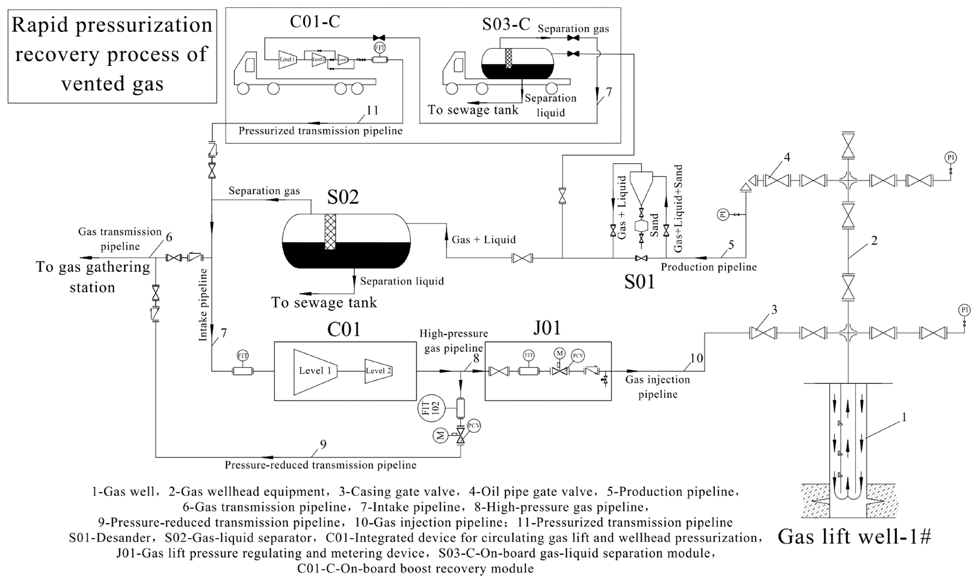
- Construction Process: The air is first separated from the gas–liquid mixture. The separated gas is pressurized and fed into the natural gas production/injection pipeline system, while the separated liquid is directed to the field sewage tank. This process ensures the sealing and rapid recovery and reuse of the air vented at the wellhead.
- (2)
- Key Technical Parameters: The critical liquid-carrying gas volume of the gas well is used as the design basis for the minimum recovery gas velocity. A venting booster device with low inlet pressure and high exhaust flow is employed to achieve the venting process, discharge accumulated liquid, and meet the self-flow re-production process requirements.
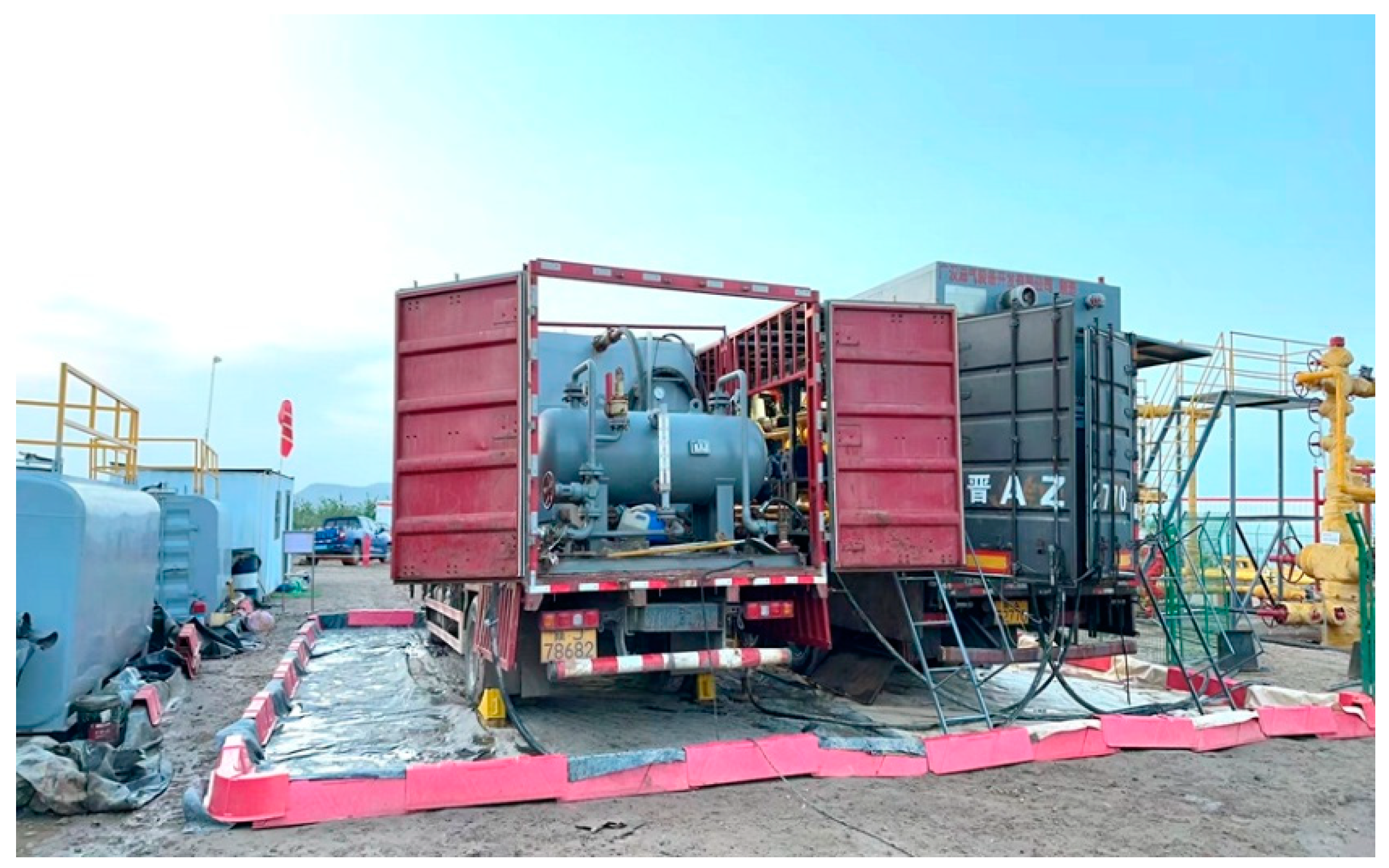
2.2.1. Gas Venting Rapid Pressurization and Recovery Device
- (1)
- Vehicle-mounted gas–liquid phase separation module
- (2)
- Vehicle-mounted pressurization recovery module.
2.2.2. Pipeline Friction Optimization
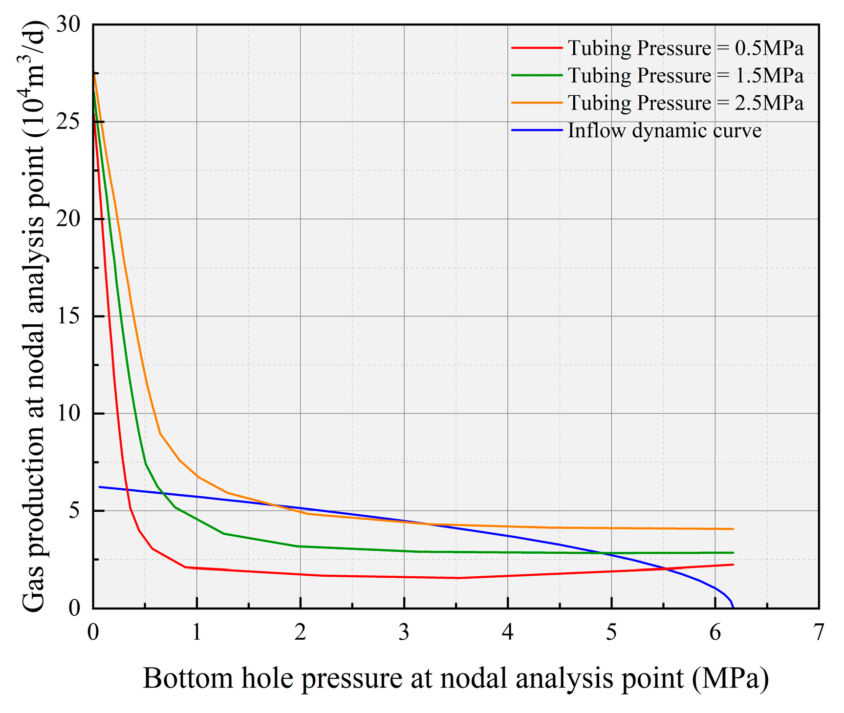
2.2.3. Gas Venting Recovery Critical Parameter Design
- (1)
- Determining the working exhaust flow of the recovery device based on the production rate at different wellhead tubing pressures.
- (2)
- Determining the working point exhaust flow rate of the recovery device based on the critical liquid-carrying flow rate.
- (3)
- Determination of the exhaust flow rate of the gas venting rapid pressurization recovery device.
- (4)
- Design of the pressurization recovery module structure
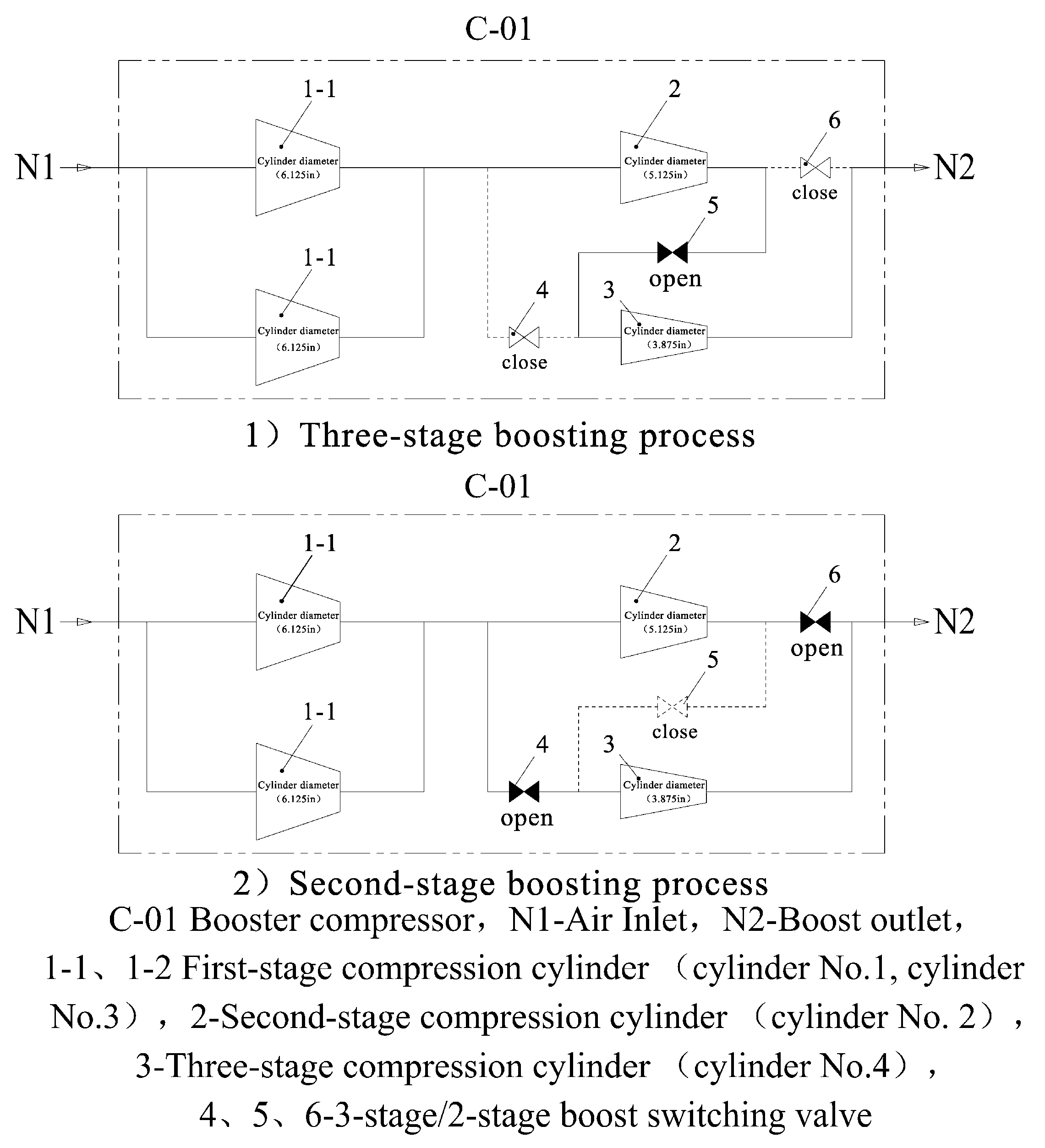
- (5)
- Design of the dual-flow switching process for the device’s compressed air cylinders.
2.3. Combined Drainage and Gas Production Process
2.3.1. The Cooperative Mechanism of Gas Lift and Wellhead Pressurization
- (1)
- Gas–liquid two-phase flow theory
- (2)
- Wellbore pressure gradient model
- (3)
- Dynamic complementarity of the pressure system
2.3.2. Production Dynamics Analysis and Parameter Optimization
2.4. Technical Route and Measures
- Lower the wellhead oil pressure to expand the production pressure differential in the wellbore, and conduct short-term, multiple rapid wellhead venting operations to efficiently discharge accumulated liquid and achieve the process objective of gas well resumption.
- Recover the vented gas in a sealed manner to reduce gas waste, protect the environment, and lower production safety risks.
- After the venting process, the well’s critical liquid-carrying capacity significantly decreases. At this point, when the gas well’s output approaches the critical liquid-carrying rate, the cyclic gas lift process is introduced into production (Figure 13) to achieve gas well activation and continuous liquid drainage.
- Gas separation is carried out, with a portion of the gas being further compressed and reinjected, while the remaining gas is directed to booster transmission equipment for entry into the pipeline network.
3. Field Test Verification of the Composite Drainage Gas Recovery Synergistic Process
3.1. Field Test of the Composite Drainage Gas Recovery Synergistic Process
3.2. Field Test Effect Evaluation
- (1)
- After implementing the combined drainage and gas production process test, the platform’s gas production significantly increased. As of 27 June 2024, the combined drainage and gas production process had been tested for 140 days, with a daily gas production of 11.32 × 10⁴ m3/d and daily water production of 4.49 m3/d, resulting in a daily gas increase rate of 35.8%. The highest daily gas production on the platform reached 5.52 × 10⁴ m3/d, with a daily gas increase rate of 54.4% (Table 6). By December 2024, the combined drainage and gas production process had been tested for 310 days, with a cumulative gas production increase of 370 × 104 m3/d, achieving significant liquid drainage and increased production results.
- (2)
- After the combined drainage and gas production process test, the bottom-hole pressures of all wells significantly decreased. Specifically, the bottom-hole pressure of Well Ping 01 reduced from 4.45 MPa before the test to a minimum of 2.26 MPa; the bottom-hole pressure of Well Ping 02 reduced from 3.78 MPa to a minimum of 2.73 MPa; and the bottom-hole pressure of Well Ping 03 reduced from 3.66 MPa to a minimum of 2.73 MPa (Figure 15).
- (3)
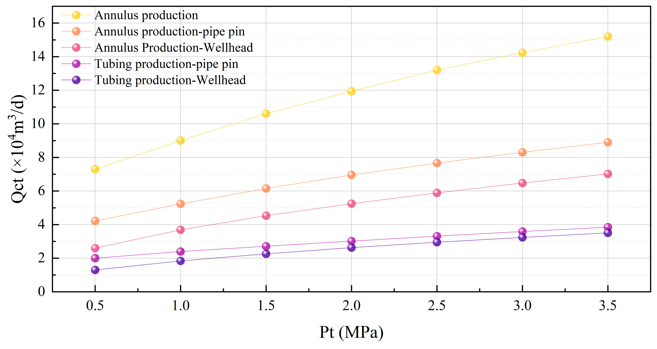
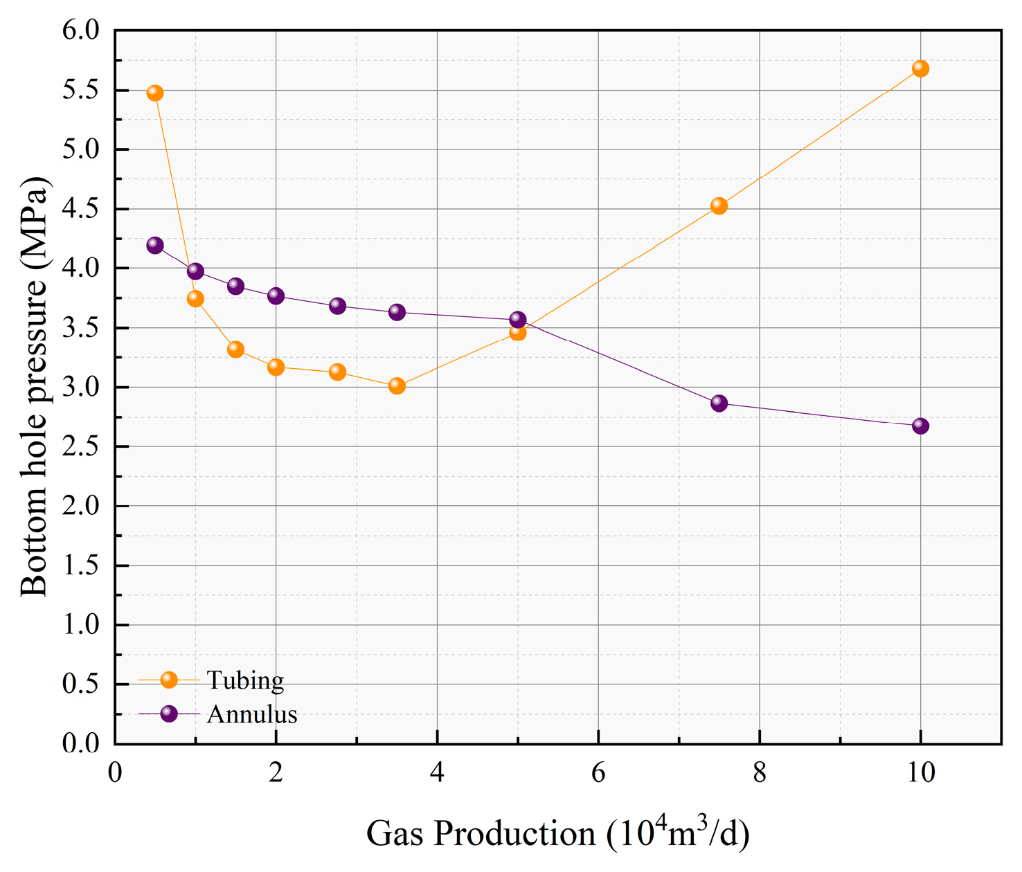
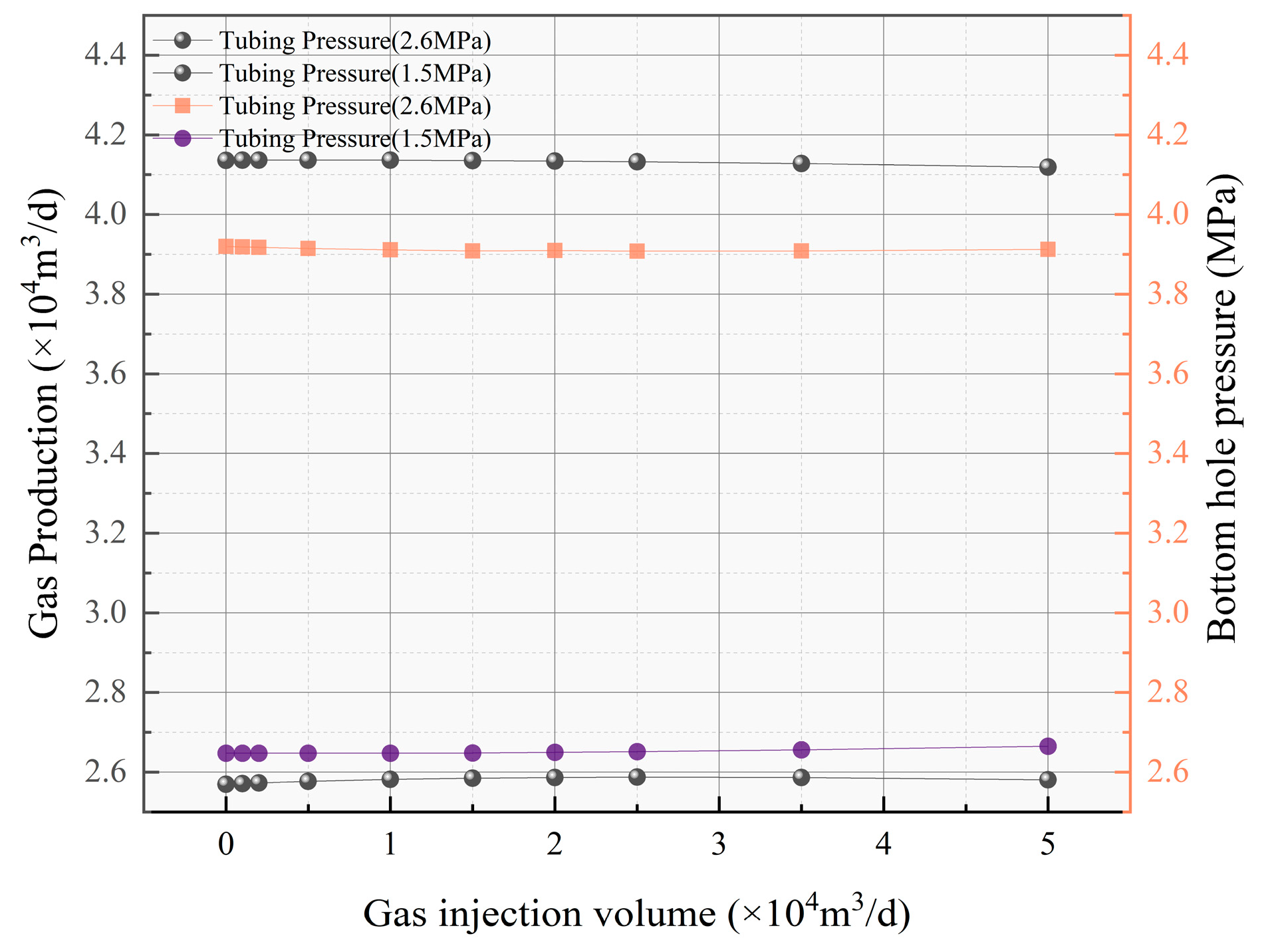
- When using annular production and injecting gas into the tubing (Figure 16), the oil pressure was reduced to 2.6 and 1.5 MPa, respectively. As the oil pressure decreased, the gas production increased from 2.6 × 10⁴ m3/d to 4.1 × 10⁴ m3/d, and the bottom-hole pressure decreased from 3.9 MPa to 2.6 MPa. However, when the wellhead oil pressure remained constant and only the gas injection rate was increased from 0 to 5.0 × 10⁴ m3/d, the gas production remained almost unchanged, and the bottom-hole pressure did not significantly decrease. Therefore, it was confirmed that during annular production, reducing the wellhead oil pressure significantly affects the reduction of bottom-hole oil pressure and increases gas production, and both bottom-hole pressure and gas production are sensitive to oil pressure. Increasing the gas injection rate has little effect on reducing bottom-hole oil pressure or increasing gas production, and both bottom-hole pressure and gas production are not sensitive to the injection rate.
- (4)
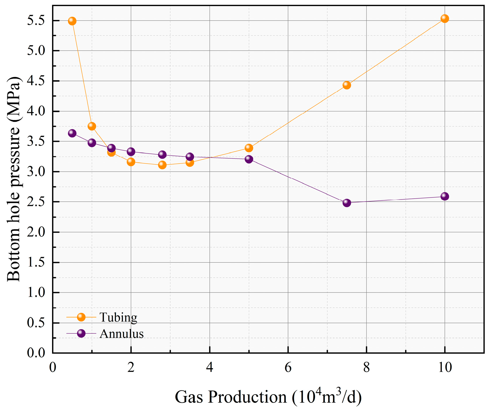
- Similarly, when using tubing production and injecting gas into the annulus (Figure 17), it can be concluded that during tubing production, both lowering the wellhead oil pressure and increasing the gas injection rate lead to significant changes in bottom-hole oil pressure and gas production. Therefore, the tubing production method is sensitive to both the reduction in bottom-hole oil pressure and the increase in gas production, whereas the annular production method is not sensitive to these factors.
3.3. Potential Input–Output Ratio of Composite Drainage Technology
4. Discussion
- (1)
- This process achieves efficient drainage and gas production through the dynamic coordination of “circulating gas lift–wellhead pressurization-venting air recovery”: wellhead pressurization quickly reduces the oil pressure (such as 2.5 MPa→0.5 MPa), expands the production pressure difference, and promotes fluid inflow; circulating gas lift pressurizes the recovered gas and injects it back into the annulus (8 MPa), pushing the accumulated liquid back up, forming a dynamic pressure balance of “low-pressure attraction–high-pressure lifting”; at the same time, the venting air recovery module realizes the closed circulation of methane (efficiency > 95%), which not only reduces dependence on external gas sources, but also reduces emissions. The three are coordinated to solve the separation problems of “difficult pressure reduction”, “difficult lifting”, and “waste of venting” in traditional processes, and achieved significant effects and advantages of reducing bottom-hole pressure by 38% and increasing daily gas volume by 35.8% on the Jishen 15A platform.
- (2)
- The results of multi-model comparison show that the Belfroid model is most suitable for the horizontal well structure adopted by the Jishen 15A platform. The model fully considers the influence of the wellbore inclination on the droplet morphology and the critical velocity of the liquid carrying, and is highly consistent with the prediction results of the on-site liquid accumulation state. In the process parameter design and gas injection rate control, the Belfroid model provides a reliable basis for the evaluation of liquid-carrying capacity, especially in the mid-to-late production stage with low pressure and low gas–liquid ratio. With the guidance of this model, the liquid-carrying efficiency has increased by more than 30%, significantly improving the overall drainage efficiency.
- (3)
- Through node analysis and multiphase flow simulation, the influence of parameter changes on the dynamic behavior of the wellbore under different production modes is clarified. In the annular production mode, reducing the wellhead oil pressure has a significant effect on increasing gas production and reducing the bottom-hole flow pressure, while simply increasing the gas injection volume has limited effect; in the tubing production mode, the bottom-hole pressure is sensitive to both oil pressure and gas injection volume, and the system control window is wider. Therefore, it is recommended to dynamically adjust the production mode according to the gas production stage and gas–liquid ratio, focusing on annular production in the early stage, switching to tubing production in the middle and late stages, matching the gas lift gas injection strategy, and further optimizing the overall drainage and production system.
- (4)
- The composite drainage gas production process adopted in this study has significant advantages: it can adapt to complex gas reservoir environments such as deep layers, low permeability, low pressure, and high water content, and combines the dynamic synergy of wellhead pressurization and circulating gas lift to improve gas–liquid-carrying capacity, reduce bottom-hole flow pressure, and extend the stable production cycle; the venting air recovery system effectively reduces environmental emissions and energy consumption, and has a high green economic value; the modular design of the equipment improves the flexibility of on-site construction and deployment, and adapts to the needs of multi-well field and multi-cycle operation. However, this process also has certain disadvantages, such as complex system structure, multiple operating parameters, and high requirements for on-site operation and control accuracy.
- (5)
- The composite drainage gas production process has shown good adaptability and promotion prospects in this study area, and is particularly suitable for coal–rock gas wells with deep reservoirs, high water production in the early stage, and rapid decline in the gas–liquid ratio in the later stage. It is recommended to further optimize and expand in the following directions in the future: first, introduce real-time dynamic monitoring and intelligent gas injection control systems to improve process response efficiency; second, strengthen the integrated application of multi-branch technology of horizontal wells and flexible pipe column drainage technology to improve the adaptability of complex wellbore systems; third, expand the test to different geological blocks and coal seam types, evaluate the universality and economic boundaries of the process, and provide more popular technical solutions for the efficient development of deep coalbed methane.
5. Conclusions
- (1)
- Through the “circulating gas lift–wellhead pressure boosting-air release recovery” synergistic process, the daily gas production at the Jishen 15A platform increased from 8.34 × 10⁴ m3 to 11.32 × 10⁴ m3, an increase of 35.8%. The average bottom-hole pressure decreased by 38%, and the liquid loading cycle was extended by 3 times, validating the dynamic pressure balance system’s efficient regulatory capability for low-pressure, low-permeability gas wells.
- (2)
- The vehicle-mounted booster device uses a three-stage/two-stage booster dual-process switching technology. With an intake pressure of 0.5 MPa, the exhaust volume reaches 10.38 × 10⁴ m3, with a recovery efficiency of ≥95%. Combined with pipeline friction optimization (DN65 pipeline pressure loss ≤ 0.16 MPa), the wellhead pressure drops rapidly from 2.5 MPa to 0.5 MPa, effectively shortening the restoration cycle to 24 h.
- (3)
- The critical liquid carry rate model was optimized, and the Belfroid liquid carry model was selected as the main model. This model incorporates the effect of wellbore inclination, guiding a 35% improvement in the liquid-carrying capacity under tubing production. After optimizing the gas injection rate, the bottom-hole pressure was reduced by 41%.
- (4)
- The synergistic composite drainage and gas recovery process significantly extended the production cycle and enhanced the overall recovery rate of the three gas wells on the Jishen 15A platform. This highlights the need for further optimization and technological advancements to improve production sustainability in deep coalbed methane development.
- (5)
- Although this study is currently based only on the test data of the Jishen 15-6A platform, due to the small number of similar well types, other wells are still in the early stages of development and have not yet entered the appropriate production stage, resulting in limited comparable application cases. We fully recognize that this is a limitation of this study. In the future, as other wells gradually enter the corresponding production stage, we will continue to carry out follow-up research and comparative verification work to further enrich and improve the adaptability analysis and application evaluation of this process under different well conditions.
- (6)
- This study focuses on the implementation effect of the composite process, so it does not include a systematic analysis of environmental impacts or related risk mitigation strategies. We recognize that such assessments usually require long-term tracking and multi-dimensional data support, which is beyond the scope of this stage of research. However, we have included environmental impact assessments in subsequent research plans, and will conduct systematic research in a broader application context in the future to ensure sustainability and environmental responsibility during technology promotion.
Author Contributions
Funding
Data Availability Statement
Conflicts of Interest
References
- Lin, L.; Lu, H.; Huang, L.; Luo, P. A molecular dynamics study of methane/water diffusion and water-blocking effects in coalbed methane. Fuel 2025, 386, 134234. [Google Scholar] [CrossRef]
- Clarkson, C.R.; McGovern, J.M. Optimization of coalbed-methane-reservoir exploration and development strategies through integration of simulation and economics. SPE Reserv. Eval. Eng. 2005, 8, 502–519. [Google Scholar] [CrossRef]
- Ahmed, A.-J.; Johnston, S.; Boyer, C.; Lambert, S.W.; Bustos, O.A.; Pashin, J.C.; Wray, A. Coalbed methane: Clean energy for the world. Oilfield Rev. 2009, 21, 4–13. [Google Scholar]
- Moore, T.A. Coalbed methane: A review. Int. J. Coal Geol. 2012, 101, 36–81. [Google Scholar] [CrossRef]
- Flores, R.M. Coal and Coalbed Gas: Fueling the Future; Newnes: London, UK, 2013. [Google Scholar]
- Lu, Y.; Yang, Z.; Li, X.; Han, J.; Ji, G. Problems and methods for optimization of hydraulic fracturing of deep coal beds in China. Chem. Technol. Fuels Oils 2015, 51, 41–48. [Google Scholar] [CrossRef]
- Chen, M.; Sun, J.; Gao, E.; Tian, H. A Summary of Wellbore Fluid Accumulation and Drainage Gas Production Technology in Gas Wells. IOP Conf. Ser. Earth Environ. Sci. 2021, 621, 12113. [Google Scholar] [CrossRef]
- Bai, X.; Rong, F.; Zhang, Z.; Xu, J.; Wang, J.; Bai, Y.; Yang, W.; Li, Y. Study on Gas Production Mechanism of Foam Drainage and Optimization of Technological Parameters. Chem. Technol. Fuels Oils 2025, 60, 1594–1603. [Google Scholar]
- Liu, P.; Chen, M.; He, Z.; Luo, W.; Miao, S. Study on a gas plunger lift model for shale gas wells and its effective application. Fluid Dyn. Mater. Process. 2022, 18, 933–955. [Google Scholar] [CrossRef]
- Yan, Y.; Li, Z.; Shao, L.; Wang, X.; Liu, W. Experimental Study on Lifting Technology of Hydraulic Driving Screw Pump. IOP Conf. Ser. Earth Environ. Sci. 2021, 769, 042066. [Google Scholar] [CrossRef]
- Liu, H.; Hao, X.; Wang, L.; Cao, G. Current technical status and development trend of artificial lift. Acta Pet. Sin. 2015, 36, 1441. [Google Scholar]
- Yang, Z.; Zhang, Z.; Qin, Y.; Wu, C.; Yi, T.; Li, Y.; Tang, J.; Chen, J. Optimization methods of production layer combination for coalbed methane development in multi-coal seams. Pet. Explor. Dev. 2018, 45, 312–320. [Google Scholar] [CrossRef]
- Qin, Y.; Shen, J. On the fundamental issues of deep coalbed methane geology. Acta Pet. Sin. 2016, 37, 125. [Google Scholar]
- Xu, F.; Hou, W.; Xiong, X.; Xu, B.; Wu, P.; Wang, H.; Feng, K.; Yun, J.; Li, S.; Zhang, L.; et al. The status and development strategy of coalbed methane industry in China. Pet. Explor. Dev. 2023, 50, 765–783. [Google Scholar] [CrossRef]
- Niu, X.; Pang, D.; Liu, H.; Zhang, Y.; Cheng, G.; Cao, J.; Zhao, Y. Gas extraction mechanism and effect of ultra-high-pressure hydraulic slotting technology: A case study in Renlou coal mine. Nat. Resour. Res. 2023, 32, 321–339. [Google Scholar] [CrossRef]
- Zou, M.; Wei, C.; Zhang, M.; Shen, J.; Shao, C. A mathematical approach investigating the production of effective water during coalbed methane well drainage: A case study on well QNPN01 of the southern Qins hui basin, China. Arab. J. Geosci. 2014, 7, 1683–1692. [Google Scholar] [CrossRef]
- Yan, X.; Zhang, S.; Tang, S.; Li, Z.; Guan, W.; Zhang, Q.; Wang, J. A prediction model for pressure propagation and production boundary during coalbed methane development. Energy Fuels 2021, 35, 1219–1233. [Google Scholar] [CrossRef]
- Wang, W.; Li, X.; Lin, B.; Zhai, C. Pulsating hydraulic fracturing technology in low permeability coal seams. Int. J. Min. Sci. Technol. 2015, 25, 681–685. [Google Scholar] [CrossRef]
- Mu, Y.; Fan, N.; Wang, J. CBM recovery technology characterized by docking ground multi-branch horizontal wells with underground boreholes. Energy Sources Part A Recovery Util. Environ. Eff. 2021, 43, 645–659. [Google Scholar] [CrossRef]
- Liu, C.; Jia, H.; Mao, S.; Cui, X.; Peng, H.; Li, X.; Zhang, G. The development characteristics and main control factors of the open-hole multi-branch CBM horizontal wells. Coal Geol. Explor. 2018, 46, 140–145. [Google Scholar]
- Yin, J.; Wu, Y.; Zhang, H.; Cao, J. A research on destress mechanism of underlying roadway for gas outburst prevention in deep, low-permeability coal seam. Energy Sci. Eng. 2024, 12, 2661–2675. [Google Scholar] [CrossRef]
- Sun, L.; Zhao, Z.; Li, C.; Feng, R.; Meng, Y.; Li, Y. Research and Application of Treatment Measures for Low-Yield and Low-Efficiency Coalbed Methane Wells in Qin shui Basin. Processes 2024, 12, 1381. [Google Scholar] [CrossRef]
- Ma, T.; Liu, J.; Fu, J.; Wu, B. Drilling and completion technologies of coalbed methane exploitation: An overview. Int. J. Coal Sci. Technol. 2022, 9, 68. [Google Scholar] [CrossRef]
- Hu, Z.; Jin, Z.; Zhang, X.; Kong, F.; Wang, J.; Luo, Y. A calculation model for critical liquid-carrying flow rate of shale gas horizontal well section. Nat. Gas Explor. Dev. 2024, 47, 18–24. [Google Scholar]
- Wang, Z.; Li, Y. The mechanism of continuously removing liquids from gas wells. Acta Pet. Sin. 2012, 33, 681–686. [Google Scholar]
- Pan, J.; Wang, W.-J.; Wei, Y.-Q.; Chen, J.-B.; Wang, L.-L. A New Prediction Model for Continuous Liquid Carrying in Gas Wells. J. Eng. Thermophys. 2019, 40, 579–586. [Google Scholar]
- Belfroid, S.P.C.; Schiferli, W.; Alberts, G.J.N.; Veekenet, C.A.M.; Biezen, E. Prediction onset and dynamic behaviour of liquid loading gas wells. In Proceedings of the SPE Annual Technical Conference and Exhibition, Denver, CO, USA, 21–24 September 2008; SPE-115567-MS. [Google Scholar]
- Li, L.; Zhang, L.; Yang, B.; Yin, Y.; Li, D. Prediction method of critical liquid-carrying flow rate for directional gas wells. Oil Gas Geol. 2012, 33, 650–654. [Google Scholar]
- Chen, D.; Yao, Y.; Han, H.; Fu, G.; Song, T.; Xie, S. A new prediction model for critical liquid-carrying flow rate of directional gas wells. Nat. Gas Ind. 2016, 36, 40–44. [Google Scholar]
- Wang, Z.; Zhang, Y.; Sun, T.; Li, Z.; Yang, Z.; Zhu, G.; Shi, H. Dynamic behavior of single drop and critical single drop carrying gas flow rate under the well condition of gas well. Oil Drill. Prod. Technol. 2021, 43, 642–650. [Google Scholar]
- Turner, R.G.; Hubbard, M.G.; Dukler, A.E. Analysis and prediction of minimum flow rate for the continuous removal of liquids from gas wells. J. Pet. Technol. 1969, 21, 1475–1482. [Google Scholar] [CrossRef]
- Coleman, S.B.; Clay, H.B.; McCurdy, D.G.; Lee, H. A new look at predicting gas-well load-up. J. Pet. Technol. 1991, 43, 329–333. [Google Scholar] [CrossRef]
- Li, M.; Guo, P.; Tan, G. New look on removing liquids from gas wells. Pet. Explor. Dev. 2001, 28, 105–106. [Google Scholar]
- Wei, N.; Meng, Y.; Li, Y.; Liu, A.; Ban, X.; Jiang, X.; Lei, Y. Research on The Liquid Droplet’s Drag Coefficient for Continuous Removal of Liquid from Gas well. Nat. Gas Technol. 2007, 1, 50–54. [Google Scholar]
- Wang, Y.; Liu, Q. A new method to calculate the minimum critical liquids carrying flow rate for gas wells. Pet. Geol. Oilfield Dev. Daqing 2007, 6, 82–85. [Google Scholar]
- Yang, W.; Wang, M.; Chen, L.; Wu, J.; Yu, P. A prediction model on calculation of continuous liquid carrying critical production of directional gas wells. Nat. Gas Ind. 2009, 29, 82–84+141–142. [Google Scholar]
- Beggs, D.H.; Brill, J.P. A study of two-phase flow in inclined pipes. J. Pet. Technol. 1973, 25, 607–617. [Google Scholar] [CrossRef]


| Well Number | Tubing Pressure | Gas Production | Liquid Production | Pipe Diameter | Gas Well Status |
|---|---|---|---|---|---|
| (MPa) | (m3/d) | (m3/d) | (mm) | ||
| 1 | 1.4 | 16,040 | 1.20 | 62 | Liquid accumulation |
| 2 | 1.3 | 15,944 | 2.09 | 62 | Liquid accumulation |
| 3 | 1.0 | 14,581 | 0.95 | 62 | Liquid accumulation |
| 4 | 1.2 | 15,551 | 2.16 | 62 | Liquid accumulation |
| 5 | 0.9 | 13,246 | 1.05 | 62 | Liquid accumulation |
| 6 | 1.5 | 17,040 | 0.45 | 62 | Liquid accumulation |
| Well Number | Tubing Pressure | Gas Production | qc/×104 m3/d | Gas Well Status | ||||||
|---|---|---|---|---|---|---|---|---|---|---|
| (MPa) | (m3/d) | Turner | Coleman | Li Min | Pan Jie | Wang Yizhong | Yang Wenming | Belfroid | ||
| 1 | 1.4 | 16,040 | 1.79 | 2.49 | 0.81 | 2.25 | 0.58 | 0.81 | 1.79 | Liquid accumulation |
| 2 | 1.3 | 15,944 | 1.74 | 2.42 | 0.79 | 2.19 | 0.57 | 0.79 | 1.74 | Liquid accumulation |
| 3 | 1.0 | 14,581 | 1.53 | 2.14 | 0.68 | 1.93 | 0.49 | 0.68 | 1.53 | Liquid accumulation |
| 4 | 1.2 | 15,551 | 1.68 | 2.34 | 0.76 | 2.11 | 0.55 | 0.76 | 1.68 | Liquid accumulation |
| 5 | 0.9 | 13,246 | 1.46 | 2.05 | 0.65 | 1.84 | 0.47 | 0.65 | 1.45 | Liquid accumulation |
| 6 | 1.5 | 17,040 | 1.85 | 2.56 | 0.83 | 2.31 | 0.59 | 0.83 | 1.84 | Liquid accumulation |
| Pipeline Length | Instantaneous Gas Volume | Starting Tubing Pressure | Pipeline Friction ΔP (MPa) | ||
|---|---|---|---|---|---|
| (m) | (m3/h) | (MPa) | DN80 Pipe | DN65 Pipe | DN50 Pipe |
| 30 | 2900 | 2.5 | 0.01 | 0.02 | 0.09 |
| 4100 | 1.5 | 0.03 | 0.08 | 0.35 | |
| 2200 | 0.5 | 0.02 | 0.08 | >0.50 | |
| 60 | 2900 | 2.5 | 0.01 | 0.04 | 0.18 |
| 4100 | 1.5 | 0.05 | 0.16 | 0.95 | |
| 2200 | 0.5 | 0.05 | 0.18 | >0.50 | |
| Well Number | Production Method | Tubing Pressure (MPa) | Casing Pressure (MPa) | Liquid Production (m3/d) | Gas Production (m3/d) | Output After Reducing Tubing Pressure Q (×104 m3/d) | ||
|---|---|---|---|---|---|---|---|---|
| Pt = 2.5 MPa | Pt = 1.5 MPa | Pt = 0.5 MPa | ||||||
| 1 | Tubing | 2.60 | 3.74 | 0.32 | 35,732 | 3.63 | 4.84 | 5.45 |
| 2 | Tubing | 2.63 | 2.60 | 0.71 | 25,595 | 3.79 | 4.67 | 5.11 |
| 3 | Tubing | 1.45 | 2.67 | 1.82 | 22,029 | 3.37 | 3.60 | 3.74 |
| Number | Pressurization Method | Main Design Technical Parameters | Remark | |||
|---|---|---|---|---|---|---|
| Intake Pressure Ps (MPa) | Exhaust Pressure Pd (MPa) | Instantaneous Exhaust Volume (m3/h) | Daily Exhaust Volume (×104 m3/d) | |||
| 1 | 2-stage boost | 0.2 | 3.0 | 1834 | 4.40 | |
| 2 | 0.5 | 3.5 | 4327 | 10.38 | Design work point | |
| 3 | 0.6 | 3.5 | 4920 | 11.81 | ||
| 4 | 0.8 | 3.5 | 6645 | 15.95 | Maximum displacement point | |
| 5 | 3-stage boost | 0.1 | 5.0 | 1152 | 2.76 | |
| 6 | 0.3 | 5.0 | 2499 | 5.99 | ||
| 7 | 0.5 | 5.0 | 3867 | 9.28 | ||
| Well Number | Before the Test (7 February 2024) | After the Test (27 June 2024) | Daily Gas Increase Rate (%) | ||||||
|---|---|---|---|---|---|---|---|---|---|
| Tubing Pressure (MPa) | Casing Pressure (MPa) | Gas Production (m3/d) | Liquid Production (m3/d) | Tubing Pressure (MPa) | Casing Pressure (MPa) | Gas Production (m3/d) | Liquid Production (m3/d) | ||
| 1 | 2.6 | 3.74 | 35,732 | 0.32 | 2.1 | 2.14 | 55,204 | 3.25 | 54.5% |
| 2 | 2.63 | 2.6 | 25,595 | 0.71 | 1.5 | 1.58 | 34,038 | 1.79 | 33.0% |
| 3 | 1.5 | 2.67 | 22,029 | 1.82 | 1.6 | 2.2 | 23,930 | 1.56 | 8.6% |
| Total | / | / | 83,356 | 2.85 | / | / | 113,172 | 4.49 | 35.8% |
| Stage | Name | 1 | 2 | Total |
|---|---|---|---|---|
| Before the test | Device Name | Wellhead booster | Gas lift compressor | - |
| Quantity | 3 | 1 | - | |
| Power (kW) | 390 | 60 | 450 | |
| Operation and maintenance costs (CNY/Day) | 6000 | 5000 | 11,000 | |
| Daily gas consumption (m3/d) | 2690 | 410 | 3100 | |
| After the test | Device Name | Integrated drainage and gas production device | - | |
| Quantity | 1 | - | ||
| Quantity | 200 | 200 | ||
| Power (kW) | 6860 | 6860 | ||
| Operation and maintenance costs (CNY/Day) | 1370 | 1370 | ||
| Reduction in operation and maintenance costs | / | / | 37.6% | |
| Energy consumption reduction | / | / | 55.8% | |
| Number | Well Number | Running Time (days) | Cumulative Production Increase (×104 m3/d) | Cumulative Output Value (10,000 CNY) | Yield Increase Effect Evaluation |
|---|---|---|---|---|---|
| 1 | 01 | 310 | 121.84 | 243.68 | Good |
| 2 | 02 | 310 | 236.88 | 473.76 | Good |
| 3 | 03 | 230 | 11.29 | 22.58 | Poor |
| Total | - | - | 370 | 740 | - |
Disclaimer/Publisher’s Note: The statements, opinions and data contained in all publications are solely those of the individual author(s) and contributor(s) and not of MDPI and/or the editor(s). MDPI and/or the editor(s) disclaim responsibility for any injury to people or property resulting from any ideas, methods, instructions or products referred to in the content. |
© 2025 by the authors. Licensee MDPI, Basel, Switzerland. This article is an open access article distributed under the terms and conditions of the Creative Commons Attribution (CC BY) license (https://creativecommons.org/licenses/by/4.0/).
Share and Cite
Sun, L.; Li, D.; Qi, W.; Hao, L.; Tang, A.; Yang, L.; Zhang, K.; Zhang, Y. Application of Composite Drainage and Gas Production Synergy Technology in Deep Coalbed Methane Wells: A Case Study of the Jishen 15A Platform. Processes 2025, 13, 1457. https://doi.org/10.3390/pr13051457
Sun L, Li D, Qi W, Hao L, Tang A, Yang L, Zhang K, Zhang Y. Application of Composite Drainage and Gas Production Synergy Technology in Deep Coalbed Methane Wells: A Case Study of the Jishen 15A Platform. Processes. 2025; 13(5):1457. https://doi.org/10.3390/pr13051457
Chicago/Turabian StyleSun, Longfei, Donghai Li, Wei Qi, Li Hao, Anda Tang, Lin Yang, Kang Zhang, and Yun Zhang. 2025. "Application of Composite Drainage and Gas Production Synergy Technology in Deep Coalbed Methane Wells: A Case Study of the Jishen 15A Platform" Processes 13, no. 5: 1457. https://doi.org/10.3390/pr13051457
APA StyleSun, L., Li, D., Qi, W., Hao, L., Tang, A., Yang, L., Zhang, K., & Zhang, Y. (2025). Application of Composite Drainage and Gas Production Synergy Technology in Deep Coalbed Methane Wells: A Case Study of the Jishen 15A Platform. Processes, 13(5), 1457. https://doi.org/10.3390/pr13051457