1. Introduction
Oil and gas well drilling, a critical global energy activity, relies on drill strings to transmit torque from the surface equipment to the bit for rock fragmentation. During drilling, particularly in deep oil wells, the drill string is affected by strong stick–slip vibrations owing to the interplay between the drill bit and the rock, as frequently noted in the field [
1]. Continuous stick–slip vibrations can lead to fatigue failure of the drill string, unexpected directional changes during drilling, and wear of the drill bit and bottom-hole assembly (BHA). These issues incur additional drilling costs and reduce drilling efficiency. As a result, it is imperative to systematically research the rapid inhibition of stick–slip vibrations to achieve safe, smooth, and efficient drilling [
2].
Establishing accurate drill-string dynamics models is essential for developing effective stick–slip vibration control strategies. Lumped parameter models have been widely employed in stick–slip vibration studies due to their fast computational speed and ease of forward implementation. Ritto and Ghandchi-Tehrani [
3] employed a simplified lumped mass parameter model to analyze the control effect of the linear quadratic regulator controller on stick–slip vibrations. Laib et al. [
4] investigated the impact of a hybrid fuzzy proportional–integral–derivative (PID) control structure on stick–slip vibrations using a four-degree-of-freedom (DOF) lumped parameter model. Nevertheless, lumped parameter models suffer from certain drawbacks, such as the simulation accuracy being contingent upon the DOF, and only limited information can be acquired for the whole drill string, with the exception of the BHA. To better simulate downhole drill-string behavior and improve simulation accuracy, the finite element method (FEM) has been extensively employed in drill-string system modeling.
The FEM exhibits substantial flexibility in modeling complex structures. In particular, to the best of the authors’ knowledge, the six-DOF vibration and dynamic features of the complete drill string can be strictly accounted for by establishing FEM models. Previously, Millheim et al. [
5] attempted to analyze the coupled vibrational behavior of the BHA using a general finite element program. Their study focused on the interactions between torsional, lateral, and axial vibrations, and through numerical simulations, they revealed the impact of various drilling parameters on vibration characteristics, with the aim of enhancing the effectiveness and safety of drilling operations. Following that, Berlioz et al. [
6] integrated rotary dynamics theory with the FEM, employing a dual-node finite shaft element with six DOFs per node to derive a dynamic model to simulate the coupled vibration behavior of the drill string. Vromen et al. [
7] developed a multimodal torsional model using the FEM that captures the dynamics of the entire drill string, such as the BHA, tool joints, and bit–rock interactions. During the development of most FEM models, the coupled effects between torsional, lateral, and axial vibrations in the drill-string system indeed must be considered. However, for vertical wells, within the specific WOB and velocity ranges conducive to stick–slip vibrations, these coupling effects can often be considered negligible [
8].
Although FEM models offer high precision and can address nonlinearities in the drill string, they often face challenges such as excessive computational time and control difficulties when applied in actual drilling operations. Moreover, discretization using nodal coordinates can lead to excessive DOFs in the dynamic model, making it difficult to solve. To address these issues, some researchers have proposed using the modal truncation method, which is suitable for analyzing the dynamic behavior of large and complex systems, to reduce the order of FEM models. The modal truncation method constructs a modal space by selecting several dominant modes from the finite element model. These modes are then combined column by column to form a modal transformation matrix, which projects the mass, stiffness, and damping matrices onto this modal space, resulting in a reduced-order dynamic system. Khulief [
9] introduced the use of modal coordinates to alleviate the high-dimensional problems arising from nodal coordinates by excluding insignificant higher-order modes. Building on this idea, Khulief and Al-Naser [
10] applied a modal transformation to obtain a reduced-order modal model, which was subsequently extended to investigate stick–slip vibrations through the incorporation of a bit–rock interaction law under velocity-reducing effects. Compared to other popular dynamic model reduction methods, such as the Krylov subspace method and the balanced truncation method, the modal truncation method selects modes based on their frequency, making it the simplest modal reduction approach. It retains the important dynamic and frequency response characteristics of the system while offering lower computational complexity and higher efficiency, making it suitable for model order reduction in high-dimensional FEM models.
On the other hand, control methodologies for stick–slip vibrations are generally classified as passive or active based on their operational principles and practical implementations. Passive control encompasses modifying the system and setting the parameters of the drill string, optimizing the drilling components, and installing vibration dampers. This approach operates without requiring external energy input, aiming to modulate the system’s natural frequencies and energy dissipation patterns [
11]. Although passive methods demonstrate effectiveness, they tend to be more cost-intensive and time-consuming compared with their active counterparts. Consequently, active control strategies have attracted growing research attention. Hong et al. [
12] estimated the state of the drill-string system using a Kalman filter and combined it with a linear quadratic regulator to regulate stick–slip vibrations through numerical simulations. Simulation outcomes demonstrated that this control scheme could effectively manage stick–slip vibrations. Krama et al. [
13] proposed a super-twisting sliding-mode controller to combat stick–slip vibrations directly. Compared with traditional sliding-mode controllers, the proposed controller offers better tracking, quicker convergence, enhanced robustness, and chattering-free execution. Riane et al. [
14] designed an observer-based H
∞ controller with disturbance estimation to suppress high-frequency stick–slip vibrations in rotary drill strings, thereby improving torsional stability. Chang et al. [
15] combined machine learning models with traditional numerical simulation methods to determine in advance information on rock hardness and drillability based on the predicted electrical properties of the rock, thus enabling the real-time estimation of the mechanical properties of the rock during the drilling process. This finding allows for the adaptive tuning of parameters such as the WOB, enabling more efficient drilling operations and reducing the occurrence of torsional vibrations in the drill bit.
Although numerous stick–slip vibration suppression algorithms have been developed, the majority are predominantly based on lumped parameter models, whereas limited research attention has been devoted to developing control algorithms integrated with higher-accuracy FEM models. This paper addresses this gap by applying modal truncation to an existing nonlinear FEM model, resulting in a reduced-order model suitable for control applications. The effect of the WOB on rotational velocity in stick–slip vibrations is significant [
16,
17]. Nevertheless, the concept of incorporating the WOB into the design of control methods is currently in a preliminary state of research. Considering this, an innovative model predictive control (MPC) scheme with dynamic WOB (DWOB) is proposed (DWOB-MPC) in this paper. This scheme considers the relationship between the actual WOB and the target WOB and analyzes the superior performance of DWOB-MPC in controlling drill-string stick–slip vibrations through MPC simulation experiments.
The organizational structure of this article is as follows. First, we analyze the forces on the drill string and establish a complete nonlinear FEM model. Next, a control-oriented reduced-order model is obtained through the modal truncation and numerical analysis methods. Subsequently, the control structures of PI and MPC are described in detail, and controllers are instantiated based on the research. Finally, considering the unique changes in the dynamic WOB, we propose a DWOB-MPC comprehensive control strategy and verify its stability and reliability. The key findings of this work are expected to provide theoretical guidance for the automation and intelligent growth of the oil and gas industry.
2. Model
Based on the nonlinear dynamic drill-string model established by Wilson and Heisig [
18], this section introduces the boundary conditions of the bit–rock interaction and establishes a nonlinear FEM drill-string model for studying stick–slip vibrations. First, the Timoshenko beam element is discretized into a usable nonlinear finite element analysis form. Then, the local stiffness, mass, damping, and external force matrices are ascertained by employing Hamilton’s extended principle of virtual work. Finally, a thorough nonlinear FEM model of the drill string is established.
The derivation of a FEM model commences with the application of Hamilton’s extended principle of virtual work for a transformable object [
19], which is mathematically represented as
The variables in the equation are defined as follows:
represents the kinetic energy,
U represents the strain energy,
represents the impact of the external forces working on the object of interest, and the
operator reflects the primary variation of a function with regard to virtual movement.
2.1. Discretization of Drill-String Elements
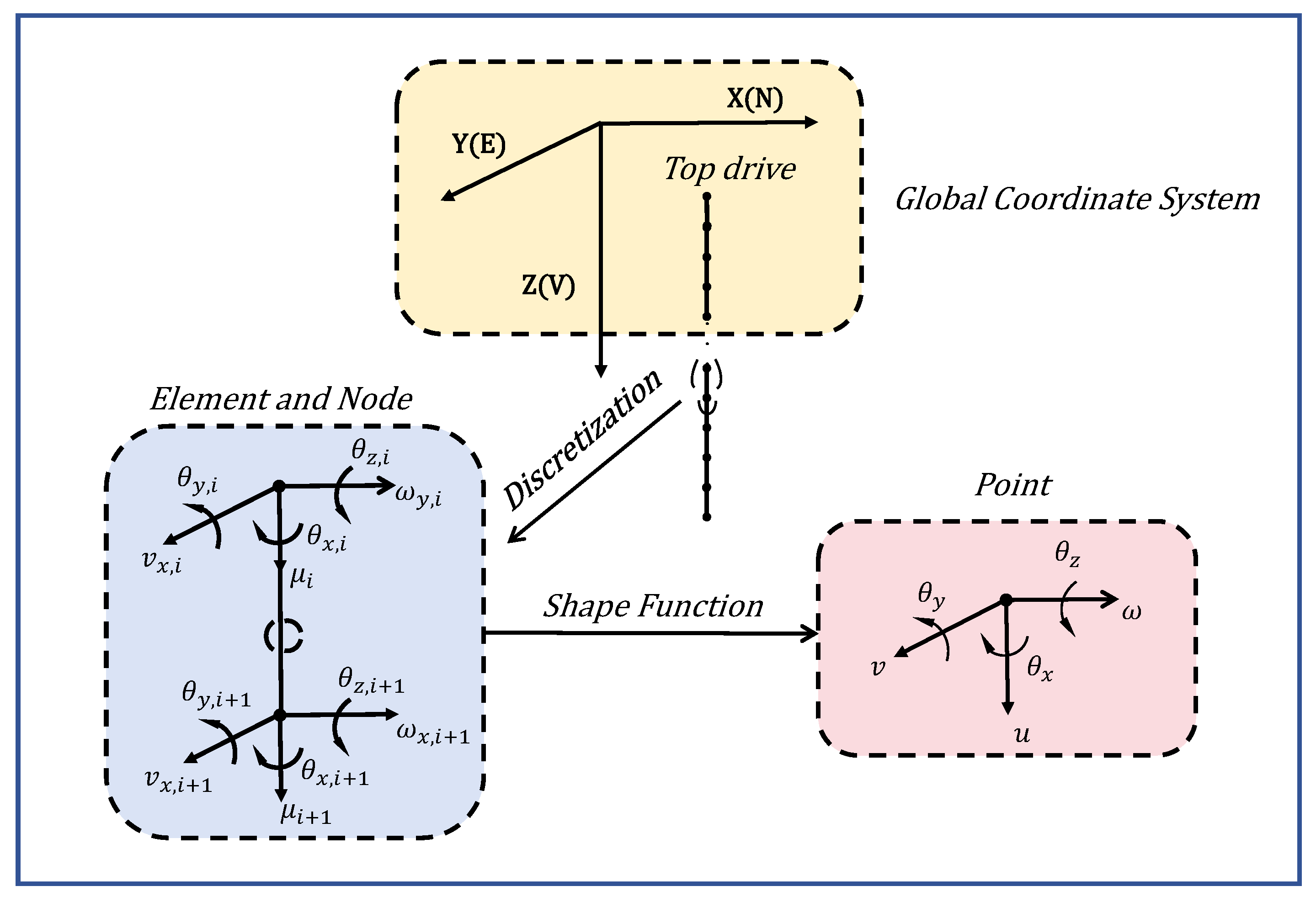
This section sets the well’s central axis as a reference and discretizes the vertical drill string along the drilling direction, with the aim of describing the structural characteristics, as illustrated in
Figure 1, where X, Y, and Z are the global coordinate axes, corresponding to the northern, eastern, and vertical orientations of the Earth.
The drill-string model in this study is discretized into multiple elements, with the top drive represented as a rigid body with a rotational DOF along the
z-axis. The drill pipe is composed of 20 beam elements. Similarly, the BHA consists of seven beam elements, each formed of two nodes. Each node, except for the one connected to the top drive, has six DOFs. The drill bit is represented as a rigid body with six DOFs, connected to the last node of the BHA. To characterize the element displacement vector
u, twelve parameters are required.
The displacements of nodes
i along the local directions
,
, and
are expressed by
,
, and
, respectively. The localized rotations of nodes along the axes
,
, and
are represented by
,
, and
, respectively.
Introducing the shape function matrix
, the element displacement vector
can be determined by applying
where
,
,
,
,
, and
are vectors consisting of shape functions. Shape functions are a fundamental tool in finite element analysis that help discretize the displacement field by representing the displacements within the drill-string cell as interpolations of the nodal displacements, allowing complex structures to be approximated by a finite number of nodes.
2.2. Internal Forces of the Drill String
Nachbagauer [
20] presented an expression for the inner strain energy of a shear transformable beam based on the mechanics of the structure. Subsequently, by considering the primary variation, one can derive an equation representing the inner force vector of the beam:
and the scalar quantities
and
are given by
where
E means Young’s modulus of the material;
I stands for the area moment of inertia;
means a constant value that is used in the equation to calculate the overall deformation curvature of the central axis of the beam;
G stands for the shear modulus;
A refers to the cross-sectional area;
means the shear correction coefficient;
J refers to the polar area moment of inertia of the material;
l stands for the length of the drill string; and the vector-matrix
h is made up of the shape functions discussed in the preceding section.
2.3. External Forces Subjected to the Drill String
Due to the focus of this paper on torsional vibration and to facilitate model calculation and analysis, it is assumed that the model focuses on torsional DOFs. The influence of other DOFs on torsional vibration can be ignored. This paper also assumes that the research object is a vertical well and that the drill string remains unaffected by the fluid force exerted by drilling fluid when moving at the bottom of the hole. Therefore, only the effects of gravity and bit–rock interaction on the model are taken into account.
The gravitational vector exerted on each drill-string element is defined by the virtual work of external forces, in accordance with Equation (
1):
where
is the effective buoyed weight of the drill string and
represents the gravitational components acting along the X, Y, and Z axes.
The torque resulting from the bit–rock interaction is represented by applying a dry friction model [
21]. The reaction torque in this model is represented by Equation (
7), which can be categorized into three scenarios:
In the stick phase, which occurs when the magnitude of the drill-bit velocity equals or is below a certain limit value , the response torque equals the drill-bit torque, as long as it does not surpass the maximum permitted response torque ;
Simultaneous cutting and friction occur during the viscous sliding transition stage;
In the slip phase, which occurs when the absolute value of the is greater than , the absolute value of the response torque declines exponentially from the maximum allowed torque to a restricting torque value that corresponds to larger angular velocity values.
The limit value
for the angular velocity that determines the change from the stick phase to the slip phase is denoted as
rad/s. The torque
T exerted on the drill bit by the drill string, specifically during the stick phase, can be estimated by multiplying the equal torsional stiffness of these element nodes near the drill bit by the difference in angular displacements. The normal force, denoted as
, is equivalent to the WOB that is established. The parameters
,
, and
represent the coefficients of the dry friction model.
2.4. Mass, Stiffness, and Damping Matrices
The unit mass matrix originates from the kinetic energy
in the principle of virtual work, which is expressed as
The stiffness matrix is obtained in an incremental time-stepping manner, with the system stiffness at each time step expressed as follows:
The iterative calculations are performed using the given time step, resulting in the determination of the values of the effective stiffness matrix. Once the stiffness and mass matrices are provided, the Rayleigh damping matrix can be defined as
In particular, the structural damping parameters,
and
, can be derived based on the damping proportion of a part. The Rayleigh-type damping matrix is widely used due to its simplicity and effectiveness in capturing the essential damping behavior of beam element structures.
In conclusion, the complete nonlinear finite element drill-string dynamics formula can be stated as follows:
where the vector
u stands for the displacement of the system and the vector
F encompasses the aforementioned internal forces, gravity, and the forces resulting from the bit–rock interaction.
3. Reduced-Order Model
Despite the established nonlinear FEM model accurately capturing the complete dynamics of the drill string, it suffers from certain limitations, such as the complexity of controller design and the extensive computational time required. To enhance its practicality in control algorithm design, a model reduction technique is employed in this section. A control-oriented reduced-order model is obtained by utilizing a modal truncation method based on the FEM model. This approach is particularly valuable for analyzing the dynamic characteristics of large-scale and complex engineering systems. The derived reduced-order model serves as a solid foundation for future research endeavors in control algorithm development.
Prior to the model reduction procedure, the present study initially resolves the established model using the Newton–Raphson method [
22]. This step facilitates the extraction of numerical solutions for the stiffness, mass, and damping matrices, which are crucial for constructing the reduced-order model. Subsequently, Equation (
11) is expanded into a state-space form, resulting in the following expression:
which can be further simplified to
A set of selected complex eigenvectors is given, forming two complex modal matrices, denoted as matrix
R and matrix
L. Also given are the eigenvectors and the modal coordinate vector for the major modes, denoted by the vector
e. A conversion model, denoted as
, is adopted to transform the coordinates. The transformation of Equation (
13) into the truncated modal form of the motion equation is expressed as
where
and
stand for the reduced modal matrices and
is the reduced modal forcing vector. Ultimately, the control-oriented reduced-order dynamic FEM model takes the following form:
where
X is the state variable,
denotes the input, and the dynamic matrices
A and
B are calculated using numerical solution computations. The output
y represents the drill bit’s torsional angular velocity.
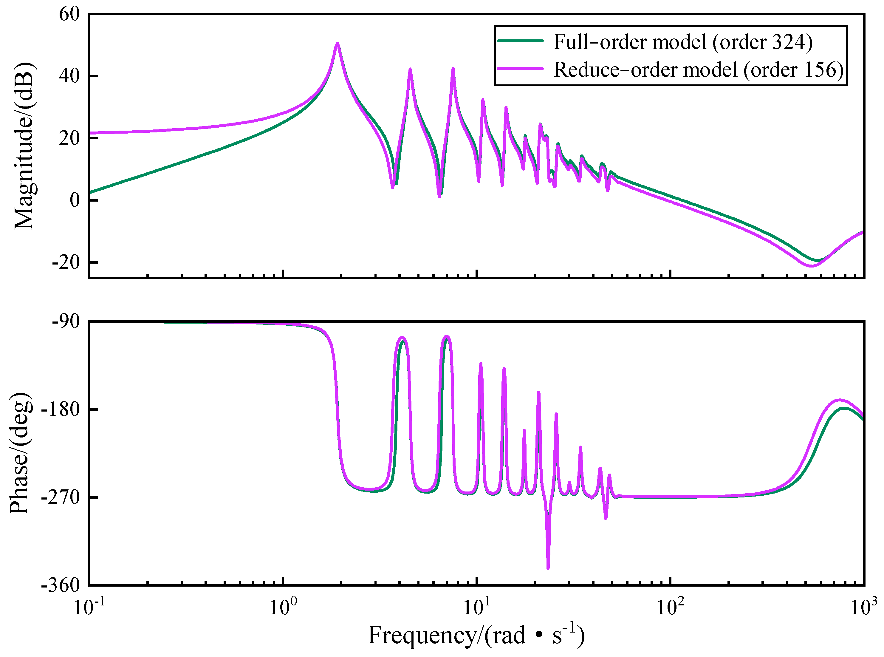
The modal truncation method generally retains modes based on their natural frequencies and corresponding damping ratios. Since the frequency of stick–slip vibrations is relatively low, this section discards non-dominant high-frequency modes and retains low-order modes with natural frequencies below the selected cutoff frequency and damping ratios within the specified range, which are used to compare the dynamic responses between the full-order and reduced-order models [
23], as shown in
Figure 2. This ensures that the retained low-order modes accurately represent the main dynamic behavior of the system while reducing computational complexity.
The full-order model includes data for 27 elements, each with 6 DOFs. Based on Equation (
12), each mode consists of both displacement and rotational velocity states, resulting in a total of 324 state variables. It can be seen that the reduced-order model obtained through modal truncation eliminates high-order modes, reducing the order to 156. Since this study focuses on torsional vibrations, all 27 torsional modes are retained, and the remaining ones are the other modes. The final model is a high-fidelity, control-oriented model, greatly facilitating control design.
4. Angular Velocity Control Design Based on the Reduced-Order Model
The control research of drill-string stick–slip vibrations usually considers only the control of angular velocity by the top-drive system of the drilling platform, which is achieved by employing a feedback control strategy that adjusts the top-drive torque to keep a constant target angular velocity. The PI controller is the most frequently utilized control algorithm in this context [
24,
25].
Therefore, the top-drive torque, denoted as , is solely determined by the deviation, , between the target and actual angular velocities. Nevertheless, on account of the inherent high flexibility of the drill string and the high counteractive frictional forces at the drill bit, applying the conventional control technique typically results in undesired oscillations in the drill bit’s angular velocity.
In contrast to the active control methods mentioned in the existing literature, this study employs the MPC method to investigate the control of stick–slip vibrations [
26]. The MPC approach is based on the finite-time-domain online optimization method, which solves constrained quadratic or nonlinear programming problems online at each sampling time. By taking into account a combination of various performance indicators, the future state variables and output values of the system can be reliably predicted. The problem of stick–slip vibrations is formulated as
In the optimization problem above, represents the optimization time domain, represents the control time domain, and in many cases, . represents the predicted output values, specifically the drill bit’s angular velocity output. represents the desired output value, which is the target angular velocity setpoint. corresponds to the control action increment, typically incorporating soft constraints to mitigate abrupt changes. The matrices S and R are the error-weighting matrix and the control-increment weighting matrix, respectively, which determine the overall dynamic performance of the control system. In this study, they are dynamically adjusted based on extensive experimental results, such as a faster settling time and low overshoot, to obtain the optimal value.
The constraints in Equation (
17) are determined based on the physical and operational limitations of the drill-string system to ensure system performance while avoiding violations of safety constraints [
27]. An upper limit of 25 rad/s is set for the control input top-drive velocity
and the rate of change
, based on the rated power and voltage range of the top-drive motor; the range of
is given as 0–5000 Nm, in accordance with the physical constraints and safety margins of the drill velocity.
As depicted in
Figure 3, the controller incorporates the concepts of optimality and prediction.
Through real-time updates of its internal model, MPC dynamically predicts the optimal output value of the control system at the next time step, known as the top-drive torque . Consequently, the drill string is driven to perform the rotational motion, propelling the movement of the drill bit and enabling feedback correction. Furthermore, the controller is capable of handling different constraint conditions, showcasing robustness and adaptability in the face of dynamic external variations.
Taking into account the drilling process, it is inevitable that the effect of the bit–rock interaction induces fluctuations in the WOB, which, in turn, impact the nonlinear frictional forces between the drill bit and the rock. The drill bit’s angular velocity is indirectly altered, leading to stick–slip vibrations. Thus, considering the practical operability of the field [
24,
28], this study integrates the WOB by manipulating the big hook load, which is a common method for field engineers to adjust the dynamic WOB, as shown in Equation (
18). Within this context, the actual WOB can be decomposed into two distinct components: the target
and a component WOB that exhibits a direct proportionality to the value of the drill bit’s rotating velocity. As the velocity increases, a corresponding increase in the actual WOB ensues.
Furthermore, the gain
of the WOB variation control is restricted based on the maximum permissible fluctuations in the big hook load, which can be dynamically adjusted by the experience value. This limitation is implemented in order to enable dynamic adjustments of the WOB in practical applications. Consequently, the reduction of
cannot be reduced infinitely. In practical field applications, the actual differences in the WOB are typically less than 15–20% of the intended WOB to ensure drilling efficiency. In other words, the control gain
is bounded.
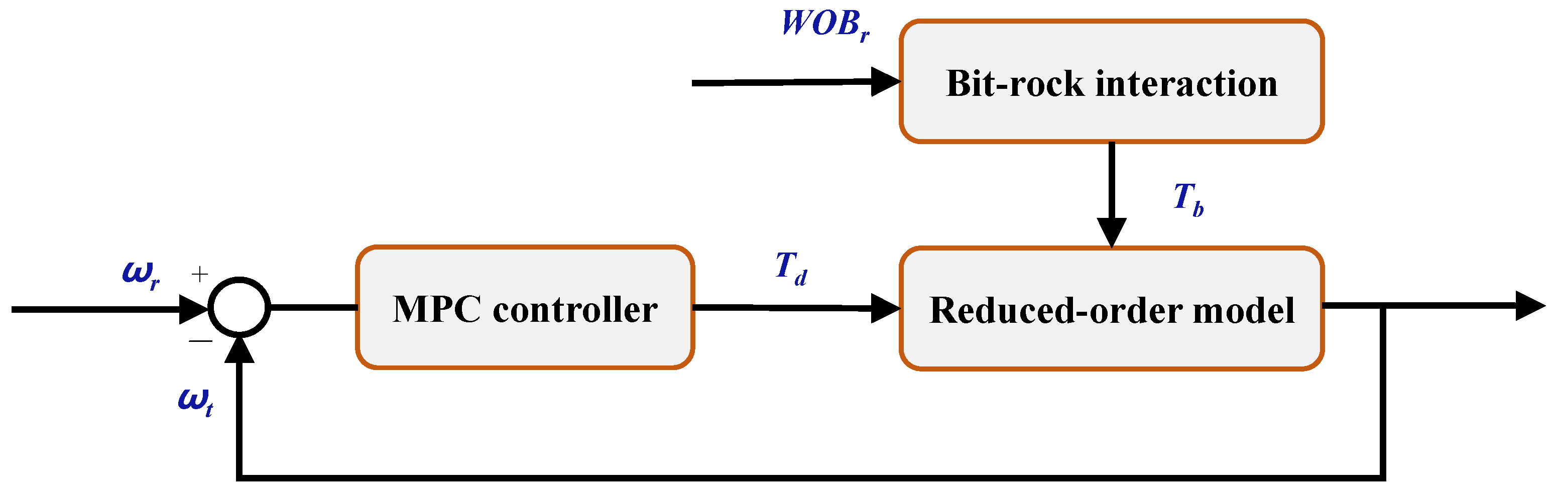
Consequently, the DWOB-MPC scheme is presented in
Figure 4.
The initial part (1) remains consistent with the conventional MPC framework, whereas the incorporation of the secondary part (2) entails dynamically modulating the magnitude of the WOB in response to any deviations between the actual and desired angular velocities of the drill bit. This modulation, in turn, alters the torque from the bit–rock interaction, thereby exerting an indirect influence on the drill bit’s velocity and expediting its convergence rate.
5. Results and Discussion
Building upon the previously established reduced-order model, this section begins by simulating downhole stick–slip vibrations to assess the model’s practicality and reliability. A comparative analysis between PI and MPC controllers follows, focusing on mitigating stick–slip vibrations and ensuring that the system accurately tracks the target drive’s velocity. Subsequently, a parametric uncertainty analysis evaluates the MPC controller’s robustness against external disturbances. Finally, the control performance of the MPC and DWOB-MPC schemes is compared.
During the simulations, the sample time was set to 0.0005 s to accurately simulate the transient response of the drill-string system. The target WOB, = 10 kN, and the top-drive velocity, = 120 rpm (12.56 rad/s), were fixed to ensure the consistency and comparability of the experimental conditions.
5.1. Open-Loop Simulation
This section employs the fourth-order Runge–Kutta (RK4) solver within MATLAB (R2020b) to simulate the stick–slip vibrations of the drill-string system over a time interval of s. The solver was equipped with a sufficiently small time step to ensure convergence even in the event of discontinuities within the system. During the simulation process, the set values of the top-drive velocity and the WOB were varied, respectively, to analyze the impact of changes in the drill bit’s torsional velocity on stick–slip vibrations.
The boundary conditions used during the simulation were as follows:
The top-drive angular acceleration was zero at the starting moment;
The top-drive velocity, , was set to the target velocity.
Table 1 shows the actual parameters of the vertical drill string, where the subscript
b represents the drill bit and the subscript
p represents the drill rod.
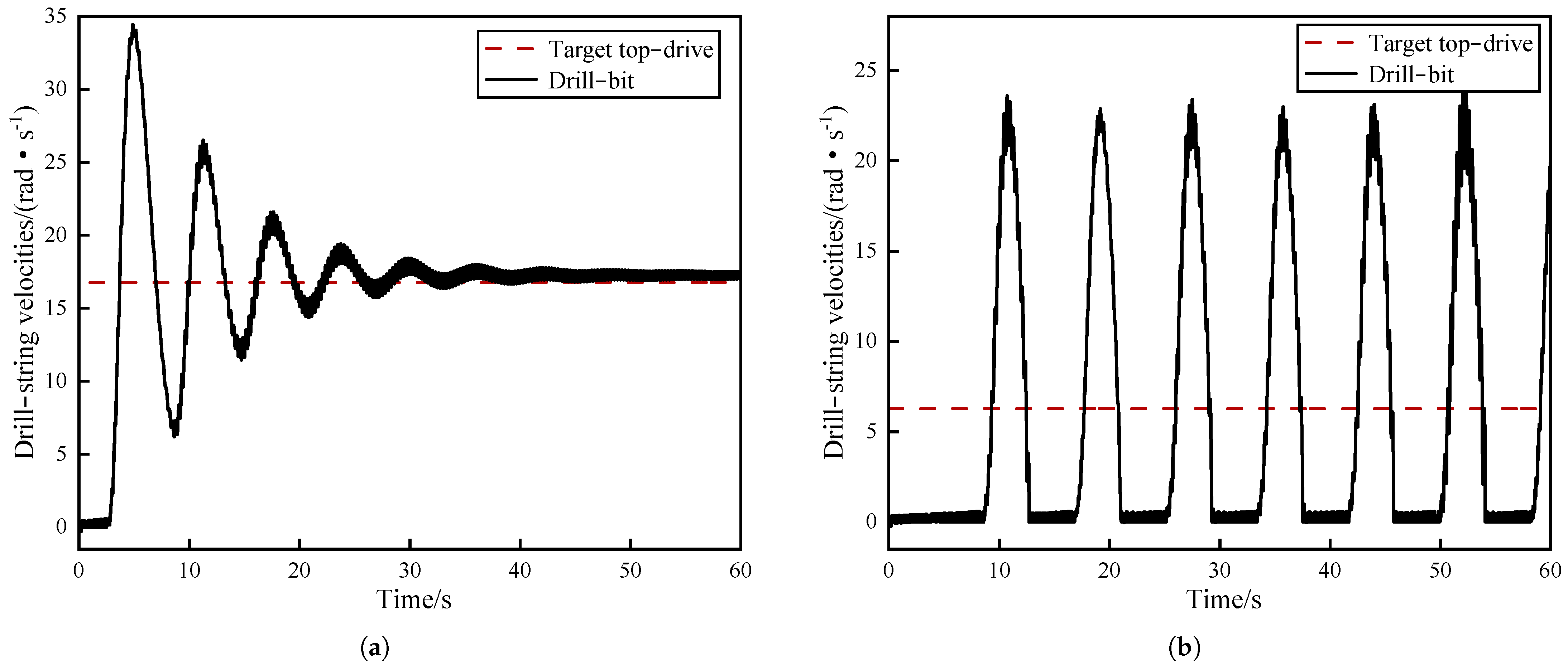
While keeping other parameters constant, periodic stick–slip vibrations occurred at the drill bit, characterized by intermittent stickiness and slippage.
The angular velocity initially fluctuated around zero, persisting for approximately 4 s before rapidly reaching a peak value. Subsequently, it fluctuated around zero again, maintaining this state for about 2 s, after which the cycle repeated (
Figure 5a). The maximum angular velocity of the drill bit reached more than twice that of the top-drive velocity, following the data from actual engineering practices [
29]. Concurrently, the torque of the drill bit showed substantial oscillations (
Figure 5b). It is evident that the velocity and torque of the drill bit oscillated with the fluctuations in the nonlinear friction torque of the drill bit, indicating that the drill string underwent stick–slip vibrations.
With all other parameters kept constant, the set values of the target WOB and top-drive velocity were altered individually to assess the influence of the drill-string system parameters on stick–slip vibrations.
Figure 6 and
Figure 7 show that a transient oscillation in the drill-bit velocity, which led to stick–slip vibrations, was observed when the WOB was reduced or the top-drive velocity was increased. However, over time, the frictional torque at the bit transitioned to sliding friction. Consequently, the angular velocity of the drill bit ultimately approached and aligned closely with the top drive. At this juncture, the stick–slip vibrations within the system were mitigated. Conversely, when the WOB was increased or the top-drive velocity was decreased, the duration of the stickiness and slippage phases at the drill bit was prolonged. Additionally, the maximum angular velocity of the drill bit increased to more than three times the set value of the top drive, exacerbating the stick–slip vibrations.
Therefore, it is evident that when the specified values of the WOB and top-drive velocity are unreasonable, a significant interactive force is generated between the bit and the rock, resulting in stick–slip vibrations. At such times, increasing the top-drive velocity or reducing the WOB can effectively mitigate stick–slip vibrations.
5.2. Closed-Loop Simulation-Based MPC Controller
The MPC controller implemented in the closed-loop simulation is presented in this section to compare its efficacy with that of the PI controller in reducing stick–slip vibrations. During the simulation, the control time domain
was set to 5, and the optimization time domain
was set to 10. The results are computed using the SQP solver, which can efficiently handle nonlinear constrained optimization problems. The simulation outcomes are depicted in
Figure 8, and the MPC control system’s steady-state and dynamic performance metrics are compared with those of the PI control system in
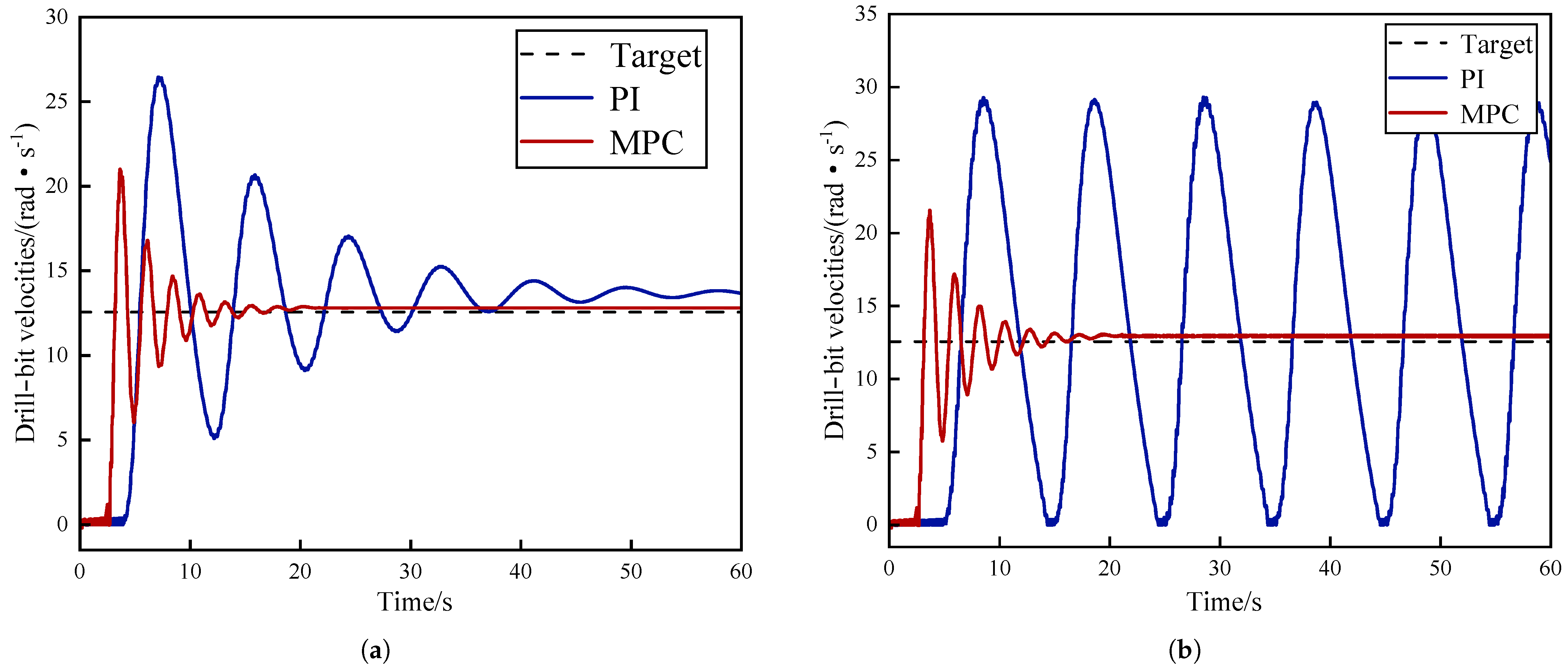
Table 2.
Under the PI controller, the drill bit’s angular velocity converged approximately after 40 s with a stable value of 12.94 rad/s, a static error of 0.38 rad/s, and an overshoot of 77.5%. Following a few oscillations, the MPC controller effectively stabilized the system, which took about 30 s. The system exhibited a low static error of 0.28 rad/s and an overshoot of 70.80%. Nevertheless, under the mutual torque between the drill bit and the rock, the drill-bit torque underwent significant and brief vibrations up and down and then tended toward a constant value. At this point, the stick–slip vibrations of the drill-string system had been eliminated. Compared to the PI controller, the MPC controller exhibited lower static errors, faster convergence, lower overshoot, and output values closer to the desired target.
Based on the analysis mentioned above, it is apparent that MPC demonstrates notable superiority in controlling stick–slip vibrations within the drill string. This controller is able to effectively control the drill bit’s velocity and stabilize it at the desired set point. In addition, in terms of static and dynamic performance, the MPC controller surpasses the conventional PI controller, exhibiting enhanced efficacy in suppressing stick–slip vibrations within the drill-string system.
5.3. Analysis of Parametric Uncertainties
The parameters of the drill-string model experience fluctuations due to various downhole conditions and specifications of drilling tools, resulting in uncertainties. For example, as the well depth increases, the length of the drill pipe increases, which affects the overall stiffness and mass distribution; high downhole temperatures may cause the material to soften and reduce stiffness, while low temperatures may increase the brittleness of the material, and the flow and pressure of the drilling fluid affect the cooling and lubrication effect of the drill pipe, which, in turn, affects its damping characteristics. The proposed controller should demonstrate a certain degree of robustness and adaptability to cope with these changes in parametric uncertainties.
This section examines the performance of the MPC controller under varying drill-string damping, mass, and moment-of-inertia parameters to investigate the impact of parametric uncertainties resulting from stick–slip vibrations. The magnitudes of these parameters were progressively decreased to evaluate different scenarios, as illustrated in
Table 3.
As shown in
Figure 8 and
Figure 9, for lower magnitudes of parametric uncertainties, the drill bit’s angular velocity exhibited intensified oscillations, an increased convergence time, and decreased stability under the PI controller. Conversely, if there are significant uncertainties in the parameters, using a PI controller will cause the system to completely diverge, resulting in stick–slip vibrations. The ongoing interaction between the bit and rock can cause fatigue and fracture of the drill string, and potentially even the loss of drill teeth, causing damage to the overall integrity of the drilling system.
Nevertheless, regardless of whether the MPC controller is faced with small or large parametric uncertainties, it maintains a consistent settling time and overshoot compared to the initial value. The overall control performance remains consistently stable and unaltered. This indicates that, compared with the PI controller, the MPC controller can respond to changes in the system state by updating the control inputs in real time through the forward-looking prediction and feedback mechanism in its optimization framework. It then effectively adjusts the control strategy to maintain the robustness of the system and enhance the adaptive capability to parametric uncertainty under complex downhole conditions.
5.4. Closed-Loop Simulation-Based DWOB-MPC Controller
The DWOB-MPC simulation added dynamic WOB auxiliary control based on the MPC control method and further optimized the real-time control of stick–slip vibrations.
Based on the data presented in
Figure 10, in comparison to the MPC controller, the system’s static error of the DWOB-MPC scheme was essentially unchanged. Moreover, it achieved a faster convergence speed. The settling time was reduced by 12 s and the overshoot by 10.8%. These findings indicate that the DWOB-MPC scheme effectively mitigates stick–slip vibrations by dampening the oscillation magnitude. This helps minimize potential damage to the drill string and enables more precise control, ultimately improving the reliability of the system.
In order to further analyze the control excellence of the DWOB-MPC scheme in terms of nonlinear finite element reduced-order model stick–slip control of drill strings, relevant evaluation indices were introduced:
where
is the square error integral,
is the absolute error integral, and
is the maximum deviation. These three indicators were used to evaluate the control effectiveness of the system.
is the integral of the squared value used to reflect the energy consumption of the system. Combining the above PI and MPC control methods, a performance index comparison of the three control methods is given in
Table 4.
The , , , and values under the DWOB-MPC control method were better than those under the PID and MPC methods, realizing more accurate, stable, and energy-efficient control. The DWOB-MPC control method better suppresses the stick–slip vibrations of the drill string and greatly improves the reliability of the system so that the drill-string system can be operated stably and efficiently under complicated working conditions.
Figure 11 illustrates the variation in the dynamic WOB. By choosing the appropriate control gain
, the actual WOB varied around the target WOB range of 15–20%. This not only ensures drilling efficiency within a practical and reasonable range but also improves the control performance of stick–slip vibrations. The results also reflect the indirect influence of the dynamic WOB control law on the control of drill-string stick–slip vibrations. As indicated by Equation (
18), the dynamic WOB relies on the error between the top-drive actual and target angular velocities. When the actual angular velocity
exceeds the target angular velocity
, increasing the actual WOB can, to some extent, amplify the counteractive torque, resulting in a further reduction in the actual angular velocity and vice versa. In addition, if the actual and target angular velocities are the same, the actual WOB equals the WOB set point. In this case, the dynamic WOB has no effect, with the top-drive torque control remaining based on the previously proposed MPC controller.
The interaction between the DWOB and the drill bit–rock friction in this control law is logically consistent. Based on this, the drill-string system can dynamically adjust the WOB, further reducing the settling time and overshoot and achieving superior control performance. However, in practical drilling field applications, due to mechanical vibration, electromagnetic interference, and other factors, the drill string may be affected by sensor noise and signal latencies, which could lead to a decrease in control effectiveness. This is an aspect that requires special attention when applying the DWOB-MPC solution to drilling sites.
Overall, the DWOB-MPC scheme has demonstrated promising results in real-time stick–slip vibration control. By manipulating drilling pressure fluctuations, it effectively regulates the nonlinear friction between the drill bit and the rock, thereby influencing stick–slip vibrations within the drill string. This control strategy significantly reduces vibration amplitude and stabilizes the drilling process, enhancing both its stability and efficiency.
6. Conclusions and Future Work
In this paper, an integrated control scheme called DWOB-MPC was proposed to guarantee the security and efficiency of the drilling process. First, a nonlinear FEM model was established to illustrate the complete dynamics of the drill string. Then, a reduced-order model was proposed utilizing the modal truncation method to solve the problem of control design. Next, two control schemes, MPC and DWOB-MPC, were introduced. Finally, stick–slip vibrations were simulated using engineering data, and the control performance of MPC, PI, and DWOB-MPC was analyzed. The dynamically adjusted, comprehensive control framework of DWOB-MPC has high potential and practical value. The main conclusions are as follows:
(1) Aiming to better describe the drill-string system, several factors, including the nonlinear drill-string model, the FEM, and the bit–rock interaction, were combined. To a certain extent, this reflects the actual drilling process more realistically and improves the practicality of the model. Engineers can also evaluate and calibrate model parameters based on experience or specific requirements.
(2) A nonlinear finite element reduced-order model was established using the modal truncation method. On one hand, the reduced-order model is complex enough to approximate the main frequency characteristics of the FEM model. On the other hand, it is simple enough to meet the design requirements of control algorithms and significantly improve numerical solution efficiency.
(3) More encouraging results were demonstrated by the MPC controller based on the reduced-order model. In terms of suppressing stick–slip vibrations, the static error of the drill bit’s angular velocity was reduced by 0.1 rad/s, and the vibration amplitude was significantly decreased. Regarding controller performance, the settling time of the MPC controller was reduced by 10 s compared to the PI controller. In particular, the noisy plant-model mismatch scenarios also demonstrated the feasibility of the MPC controller in suppressing stick–slip vibrations.
(4) An integrated DWOB-MPC scheme combining dynamic WOB and MPC was proposed for the first time to further reduce stick–slip vibrations. The innovation of this algorithm lies in its emphasis on the real-time adjustment of dynamic WOB to eliminate stick–slip vibrations. Regarding dynamic control performance, the simulation results showed that the settling time and overshoot of the DWOB-MPC controller were reduced by 12 s and 10.8%, respectively, compared to the MPC controller.
However, the current study only considered vertical wells and did not account for the additional lateral vibrations of the drill pipe. Moreover, there are no relevant field experiments to support the findings, and most of the experiments are theoretical simulations. Future work will expand the modeling assumptions to comprehensively consider the coupled effects of lateral, axial, and torsional vibrations to develop a more comprehensive drill-string model. Based on this, other more advanced active control schemes will be explored, and the impact of the rate of penetration (ROP), standard stick–slip severity index (SSSI), and bit–rock friction on the control system will be analyzed to improve drilling performance.
Meanwhile, further consideration will be given to the practical applicability of the proposed DWOB-MPC active control algorithm in the field, including the use of wired drill pipe (WDP) technology to transmit high-frequency downhole data and the estimation of unknown downhole parameters using a moving horizon estimation (MHE) algorithm to address sensor noise and latency problems.


 ,
, 


