Article

Ultra-Low Frequency Oscillation in a Thermal Power System Induced by Doubly-Fed Induction Generators with Inertia Control

1
Kunming Power Supply Bureau of Yunnan Grid Company Limited, Kunming 650011, China
2
Yunnan Electric Power Dispatching and Control Center, Kunming 650100, China
3
School of Electrical and Electronic Engineering, Huazhong University of Science and Technology, Wuhan 430074, China
*
Author to whom correspondence should be addressed.
Processes 2025, 13(5), 1368; https://doi.org/10.3390/pr13051368 (registering DOI)
Submission received: 5 April 2025 / Revised: 24 April 2025 / Accepted: 27 April 2025 / Published: 29 April 2025

Abstract

:
Ultra-low frequency oscillation has been regarded as a typical instability issue in power systems consisting of hydro turbine synchronous generators due to the water hammer phenomenon. However, the increasing installation of renewable power generators gradually changes the stability mechanisms within multiple frequency bands. In this digest, a new kind of ultra-low frequency oscillation caused by doubly-fed induction generators (DFIGs) equipped with a df/dt controller in a thermal power generation system is introduced. To reveal the underlying mechanism, the motion equation model of the DFIG is constructed, and the simplified analytical model is proposed. The results show that when integrating a df/dt-controlled DFIG into a normal three-machine, nine-bus system, the damping ratio decreases to more than 0.2 when the virtual inertia parameter increases from 5 to 20, leading to a conflict between fast virtual inertial response and stability requirements. Other controllers related to active power regulation are also vital to stability. The frequency domain characteristics of the system are studied to illustrate the influence of key parameters on system stability. Finally, simulation verifications are conducted in MATLAB/Simulink.

1. Introduction

Ultra-low frequency, whose oscillation frequency (ULFO) is under 0.1 Hz, is an instability issue. This phenomenon is reported in Yunnan, Manitoba, Nordic power systems [1,2,3], and so on. The common point of these oscillation incidents is that the power systems have a high penetration of hydro turbines. The water hammer effect is considered the root cause of ULFO. Extensive efforts have been put into solving this problem. Reference [4] proposed a small-signal model for ultra-low frequency oscillations in hydroelectric units, and mechanistically analyzed the impacts of excitation regulation and a power system stabilizer (PSS) on ultra-low frequency oscillations in the system, identifying key influencing factors. Reference [5], through an analysis of hydro turbine governor damping characteristics, indicated that an excessively low ratio between proportional and integral parameters in governors could easily induce ultra-low frequency oscillations. Reference [6] examined the influence of governor dead-zone settings on ultra-low frequency oscillations. Reference [7] investigated the mechanism by which hydroelectric unit governor systems provide negative damping during oscillations, identifying governor parameters and water hammer effects as primary causes of oscillation induction.
These studies conducted modal analysis and influence factor investigations on ultra-low frequency oscillation issues in traditional power systems. Building upon this foundation, numerous studies have explored suppression measures for low-frequency oscillations in conventional power systems. Reference [8] suggested that ultra-low frequency oscillations could be suppressed by adjusting hydro turbine governor parameters, proposing a parameter design method based on structured singular value theory. Reference [9] developed an ultra-low frequency oscillation suppression method using governor additional damping control (GPSS). Reference [10] proposed a wide area detection method to adjust the operation mode of the governor of hydraulic turbines, and the governor can be disabled when necessary. Reference [11] proposed a proportional-resonant and lead–lag series power system stabilizer and utilized a deep reinforcement learning method to realize the parameter setting. Reference [12] employed a frequency-band partitioning control concept, extending the ultra-low frequency control range by adding low-pass branches to conventional PSS, thereby constructing a novel PSS control structure for ultra-low frequency oscillation suppression. It also proposed a robust parameter tuning algorithm considering frequency-band settings and system operational condition variations. Through an analysis of ultra-low frequency oscillation phenomena in a DC island system within the Yunnan Power Grid after asynchronous interconnection, a coordinated control method between governor systems and DC frequency controllers was presented.
With the continuous construction of renewable energy generation (REG), the stability characteristic has undergone significant evolution [13]. For ULFO issues, it is important to consider the impact of REG. Reference [14] investigated modeling and stability analysis of ultra-low frequency oscillation issues in wind-integrated power systems based on the conclusion of approximately unified system-wide frequency in ultra-low frequency bands and then constructed a unified frequency model for wind-integrated power systems. Reference [15] investigated the impact mechanism of inertia-controlled wind power on ultra-low frequency oscillations through small-signal modeling and root locus analysis while analyzing the influence of patterns of wind power parameters on such oscillations. Reference [16] investigated the operational mechanisms of different frequency control strategies on prime mover system damping variations and their impacts on frequency stability using damping torque analysis. However, the modeling only considered wind power frequency response components, omitting research on other electromechanical parts. Except for wind generation, photovoltaic generators can also be employed to suppress the ULFO by adding a lead–lag section in its control loop [17]. From these works, it can be concluded that REG can have a significant impact on the ULFO in hydro power systems.
However, since REG deeply influences the stability mechanism of the power system, it is unclear whether ULFO will exist in thermal power systems. In recent years, some ULFOs have occurred in systems with thermal power and wind power generation [18,19]; thus, this issue needs to be studied. This paper innovatively discovered that doubly-fed induction generators (DFIG) with df/dt virtual inertia control can induce ULFO in thermal power generation systems. By applying the average system frequency (ASF) model, a clear explanation is brought out. The main contribution of this paper is as follows:
(1)
The properties of the DFIG are depicted by the motion equation model, which can reasonably reflect the impact of controllers within the electromechanical timescale.
(2)
Based on the cognition that frequency waveforms are approximately equal during the ULFO process, a simplified analytical model is proposed by combining the motion equation model and the ASF model.
(3)
The ULFO mechanism is revealed through the perspective of the impact of DFIG equivalent inertia on system inertia.
(4)
The impact of key parameters on stability is analyzed through frequency domain characteristics.
The rest of this paper is organized as follows. In Section 2, the structure of the thermal power generator and the DFIG is introduced, and the motion equation models are established. In Section 3 the system model is constructed, and frequency domain analysis is conducted. The analysis is verified through simulation in Section 4, and the conclusions are drawn in Section 5.

2. Modeling of Generators

To investigate the studied issue, the model of the steam turbine-based synchronous generator and the doubly-fed induction generator should be established.
(a)
The model of the synchronous generator (SG)
The entire thermal power plant consists of a synchronous generator, an excitation system, a governor, and a reheat turbine. Since the voltage regulation is a local control, and the frequency variation in the whole system is approximately the same, the excitation system is neglected in the modeling process. The block diagram of the governor and the steam turbine is shown in Figure 1a,b.
Neglecting the impact of the dead band and limiter, the transfer function of the governor is
G GS s = 1 R 1 + s T 1 1 + s T 3
The transfer function of the steam turbine is
G TB s = 1 1 + s T CH F LP + F IP 1 + s T CO 1 + s T CO 1 + s T RH + F HP 1 + s 1 + λ T RH 1 + s T RH
Denoting the inertia of the rotor by H, the motion equation model of the SG is
G SG s = 1 2 H SG s G GS s G TB s
(b)
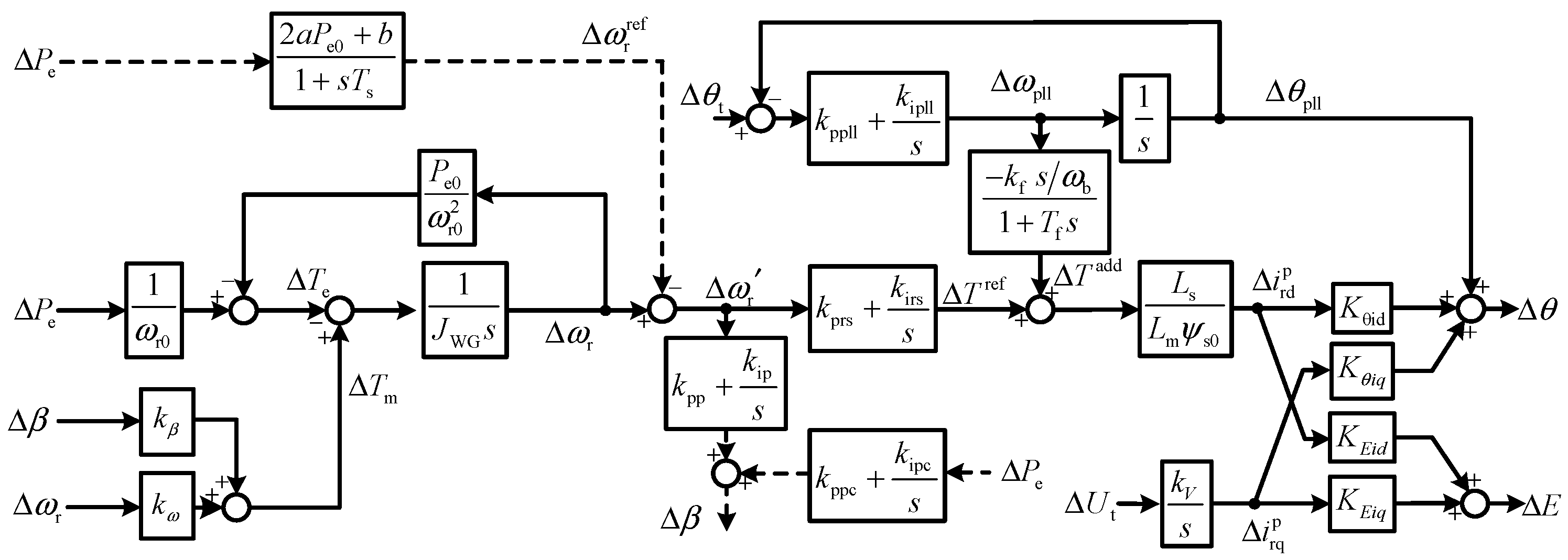
The model of the DFIG
A DFIG is a complex piece of equipment combining both mechanical and electrical sections. The characteristics of the frequency band, maximum power point tracking (MPPT), rotor, pitch control, pitch compensation control, PLL, and terminal voltage control are preserved, while the dynamics of the current controller and the grid-side converter are ignored.
The MPPT relationship can be written as ω r r e f = a P e 2 + bPe + c, where ω r r e f is the rotor speed reference value and Pe is the stator electromagnetic power, and the linearized form of the MPPT section is
Δ ω r ref = 2 a P e 0 + b 1 + s T s
where Ts is the time constant of the MPPT low-pass filter, and the subscript 0 represents the steady-state value.
When the wind speed is constant, the rotor dynamics can be represented by the following equation:
Δ T m = k β Δ β + k ω Δ ω r Δ T e = 1 ω r 0 Δ P e P e 0 ω r 0 2 Δ ω r Δ ω r = 1 J WG s Δ T m Δ T e
where Δβ is the pitch angle, ωr is the rotor speed, JWG is the rotor inertia, and kβ and kω are derived from the aerodynamic function of the wind turbine.
Denoting the proportional and integral parameter of the phase-locked loop (PLL) by Kppll and Kipll, the actual phase of the terminal voltage by θt, the frequency and phase output by the PLL by ωpll and θpll, the linearized form of the PLL can be expressed as
Δ ω pll = k ppll + k ipll s Δ θ t Δ θ pll Δ θ pll = 1 s Δ ω pll
The df/dt controller has been proposed to enhance the inertial response of REG [20]. Denoting the inertia and time constant of the df/dt controller by kf and Tf, the additional torque by Tadd, and the nominal angular frequency of the power system by ωb, the linearized function of the df/dt controller can be expressed as
Δ T add = k f s ω b 1 + T f s Δ ω pll
Denoting the PI parameter of the speed controller by kprs and kirs, the PI parameter of the pitch controller by kpp and kip, and the PI parameter of the pitch compensation controller by kppc and kipc, the linearized functions of the three controllers are
Δ T ref = k prs + k irs s Δ ω r Δ ω r ref
Δ β = 1 1 + T p s k pp + k ip s Δ ω r Δ ω r ref + k ppc + k ipc s Δ P e
where Tp is the time constant of the pitch controller low-pass filter.
Since the dynamics of the current controller are ignored, the current references are regarded as equal to their actual values. Denoting the integral parameter of the terminal voltage control by kV, the stator and mutual inductance by Ls and Lm, and the stator flux by ψs, the dq-axis current can be calculated as follows:
Δ i rd p = L s L m ψ s 0 Δ T add + Δ T ref Δ i rq p = k V s Δ U t
where Ut is the amplitude of the terminal voltage, and the superscript p represents quantities in the PLL reference frame.
Similar to the SG, the interface of the DFIG to the grid is the internal voltage. Denoting the mutual reactance by Xm, the internal voltage Ed + jEq can be expressed by (11) according to reference [21].
E d + j E q = j X m i rd p + j i rq p
The relationship between the rotor currents and the amplitude/phase of the internal voltage is algebraic, and is written as follows:
Δ θ = K θ id Δ i rd p + K θ iq Δ i rq p Δ E = K Eid Δ i rd p + K Eiq Δ i rq p
where Kθid, Kθiq, KEid, and KEiq are linearization coefficients.
Combining (4)~(12), the linearized model of the DFIG is established, as shown in Figure 2.
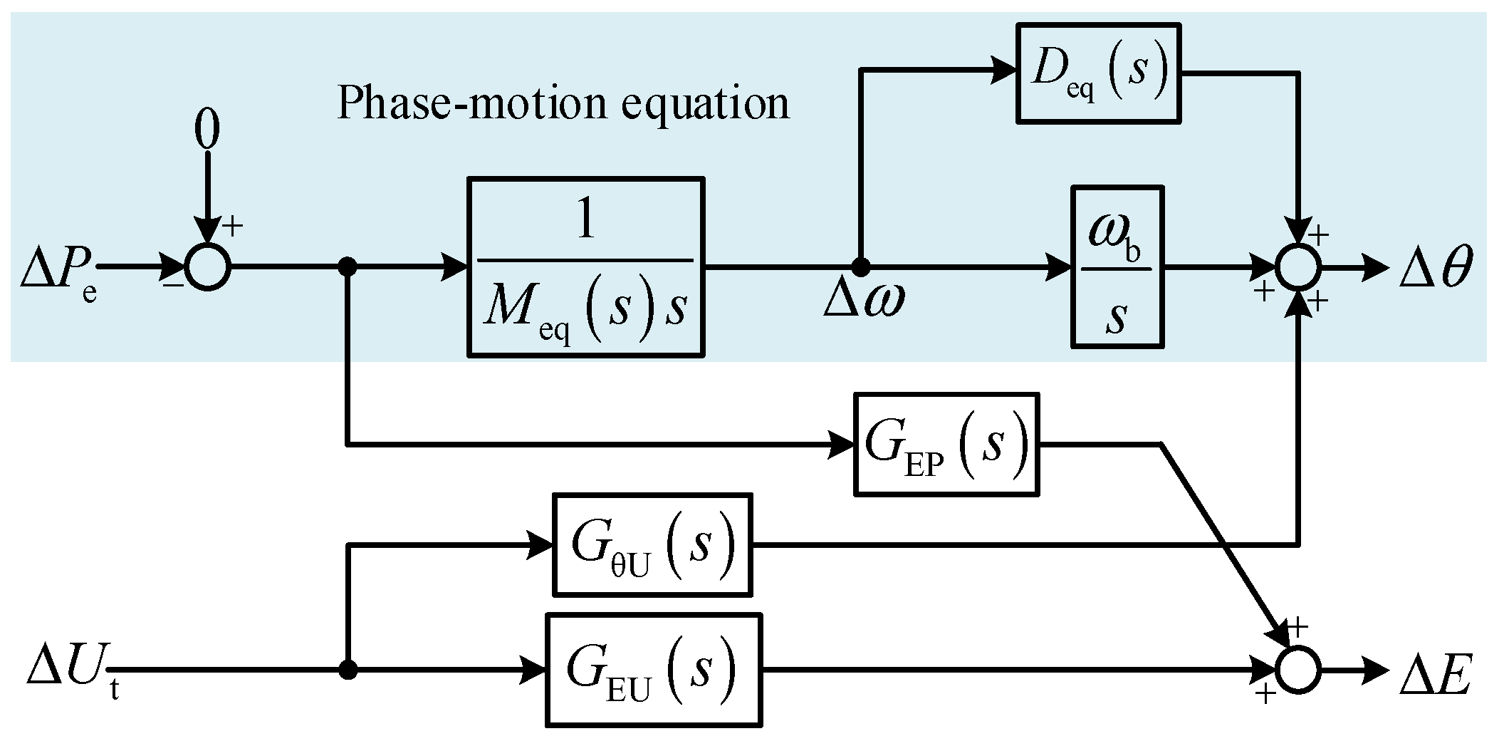
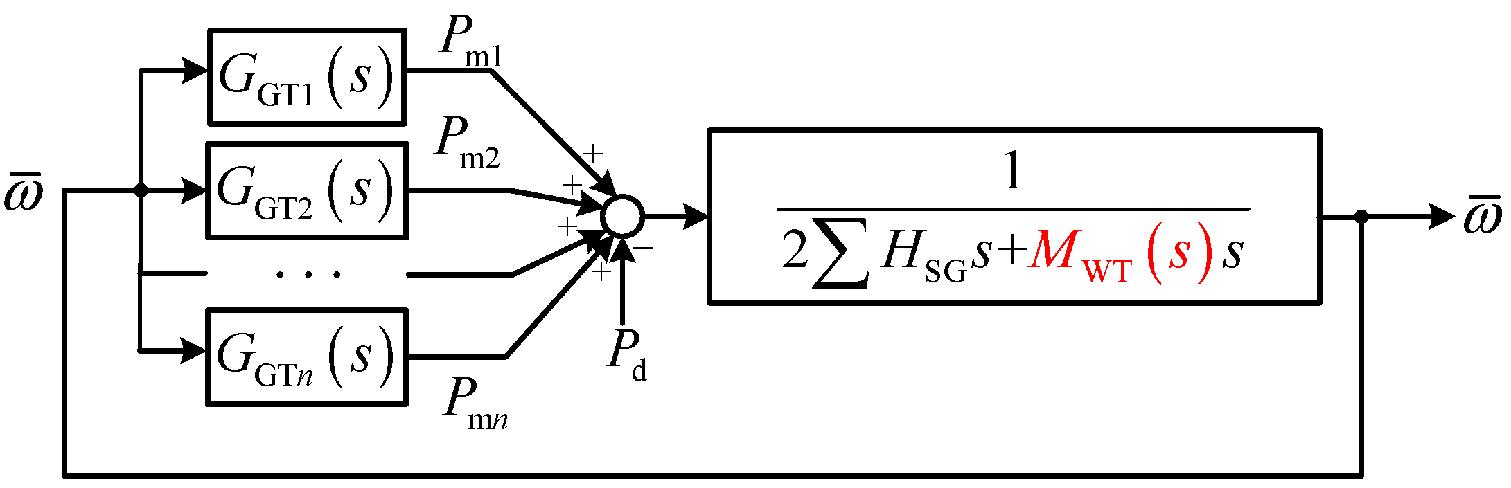
The linearized model of the DFIG can be reorganized in a form similar to the model of the SG [22,
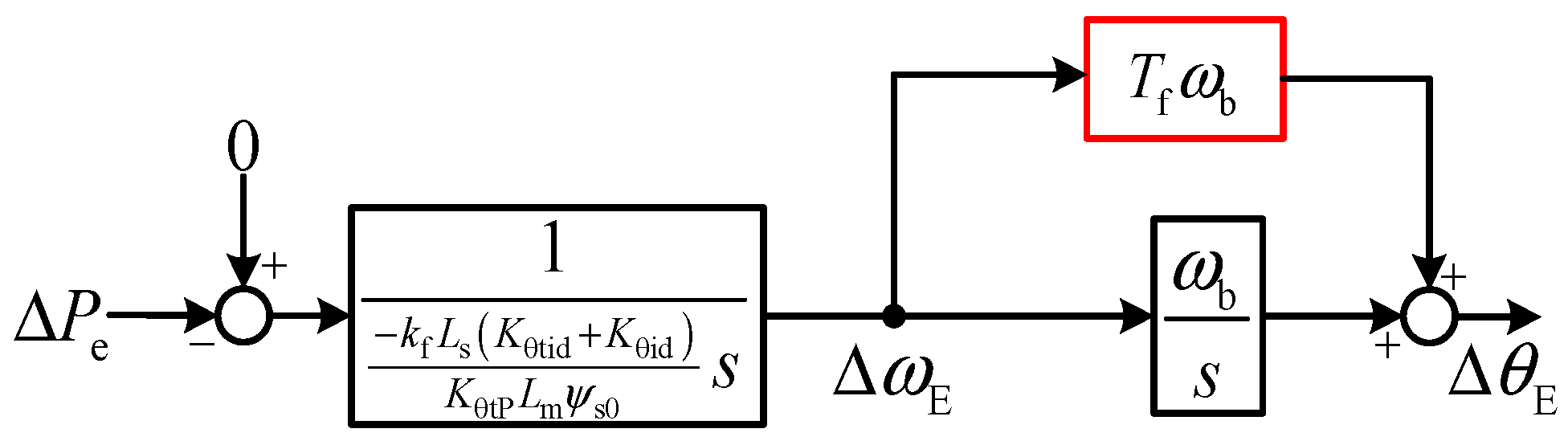
23]. To simplify the description, the motion equation model of the DFIG is directly given, as shown in Figure 3. Meq(s) and Deq(s) are called the equivalent inertia and damping of the DFIG.
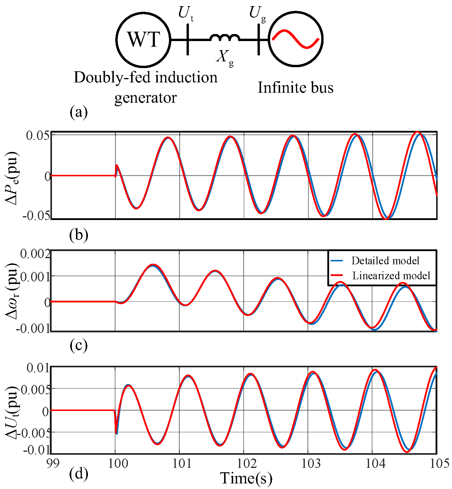
To verify the applicability of the proposed model for the DFIG, a single machine-infinite bus system is utilized, where a phase disturbance is added to the phase of the infinite bus. The response of the DFIG is shown in Figure 4. The results imply that the motion equation model is suitable for the ULFO study.

3. Mechanism Analysis

3.1. System Model

As stated in the previous section, the frequency waveforms of all devices during the ULFO tend to be the same; thus, the average system frequency model can be applied to derive a simple analytical model.
According to Figure 3, only the phase-motion equation branch is preserved during the system modeling process. The following quantity is defined in Equation (13):
M WT s = M eq s 1 + s D eq s / ω b
The ASF model of the system can be represented by the block diagram shown in Figure 5, where ω ¯ is the average frequency of the system, and GGT(s) = −GGS(s)GTB(s).

3.2. Oscillation Mechanism

The oscillation mechanism can be revealed by analyzing the impact of MWT(s) on the system inertia.
To provide a clear statement, it is first assumed that the speed control is very slow. In this case, the relationship between the unbalanced active power and internal voltage phase is shown in Figure 6. The relationship between ΔPe and ΔθE is not linked by integral sections. The existence of the term Tfωb results in a proportional-integral relationship between the frequency and phase of the internal voltage. Thus, the equivalent inertia of the DFIG is not a constant. As shown in Figure 7, the equivalent inertia of the DFIG introduces a negative phase within the frequency band (0.1, 10) Hz; thus, the phase margin of the whole system is reduced, which increases the risk of ultra-low frequency oscillations.
Moreover, since the ULFO risk does not exist in a system consisting of only thermal power generators, it can be concluded that the negative phase introduced by the DFIG is very crucial for inducing the ULFO.

3.3. Key Influencing Parameters and Influence Trend

Every section that is contained in the phase-motion equation can have an impact on the stability. To conduct the quantitative analysis, the extended three-machine, nine-bus system is utilized, as shown in Figure 8. A DFIG-based wind farm is connected to the load 3 node through a transformer and a transmission line.
The open-loop transfer function of the system is defined by Gop(s), and the phase margin of the open-loop transfer function reflects the stability [24]. Its expression is as follows:
G op s = i = 1 n G GT i s 2 i = 1 n H SG i s s + M WT s s
(a)
The impact of df/dt parameters on system stability
Decreasing the time constant Tf decreases the phase margin, illustrating that the stability deteriorates, as shown in Figure 9a. Increasing the virtual inertia kf decreases the phase margin, as shown in Figure 9b, meaning that the system diverges more easily. The numerical results are shown in Table 1 and Table 2.
(b)
The impact of speed control parameters on system stability
Several sets of speed control parameters were investigated. Since the speed control is a second-order section, the parameters shown in Figure 10a were selected to change the bandwidth. The phase margin first decreases and then increases, meaning the stability first weakens and then strengthens. The numerical results are shown in Table 3.
(c)
The impact of wind speed on system stability
As the wind speed changes, the operational region of the wind turbine switches, and the expression of MWT(s) has a different expression, which may influence the stability. As shown in Figure 10b, within the MPPT region, with the wind speed increasing, the phase margin of the open-loop transfer function decreases, and the system stability becomes worse. Within the constant speed and constant power region, the phase margin increases with wind speed, and the stability is enhanced. The numerical results are shown in Table 4.
(d)
The impact of MPPT on system stability
When the wind turbine operates within the MPPT region, the electromagnetic and mechanical power are first filtered and then inputted into the MPPT calculation. Thus, the filter time constant can influence the stability. As shown in Figure 11a, the phase margin decreases with Ts, and the system becomes more unstable. The numerical results are shown in Table 5.
(e)
The impact of the pitch control parameter on system stability
From Figure 11b, it can be seen that when the wind farm operates within the constant power region, the system becomes more stable with an increase in the pitch control parameter. The numerical results are shown in Table 5 and Table 6.
(f)
The impact of the pitch compensation control parameter on system stability
The pitch compensation controller is a first-order section. The result in Figure 12 shows that when the bandwidth of the pitch compensation control increases, the system first becomes more unstable and then more stable. The numerical results are shown in Table 7.

4. Simulation Verification

In order to verify the analysis in the previous section, simulations were conducted using MATLAB/Simulink R2021a. The studied system is identical to that shown in Figure 8.
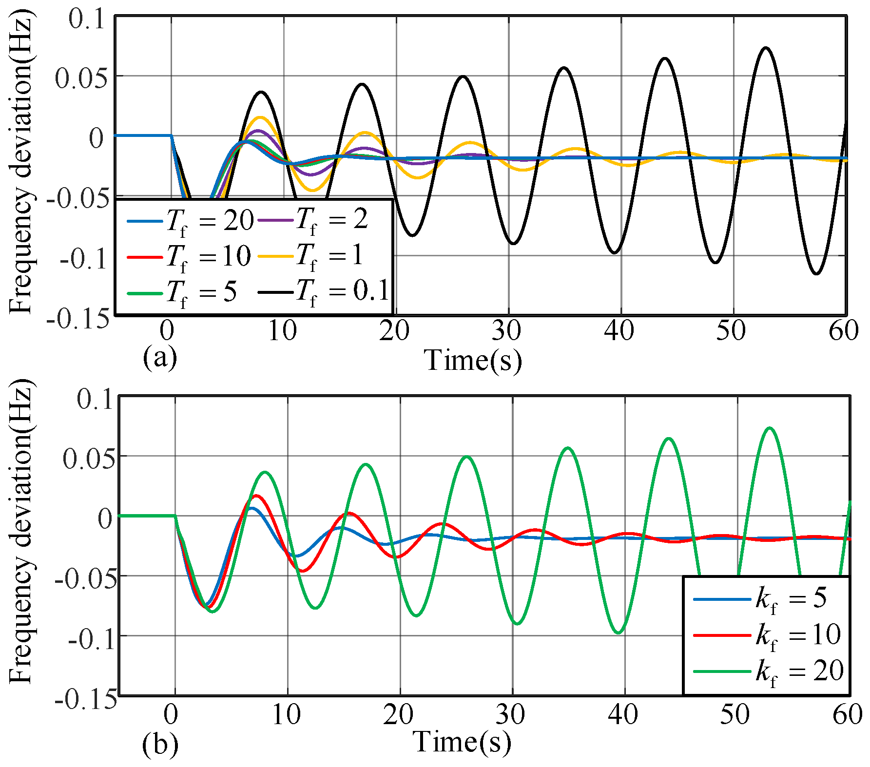
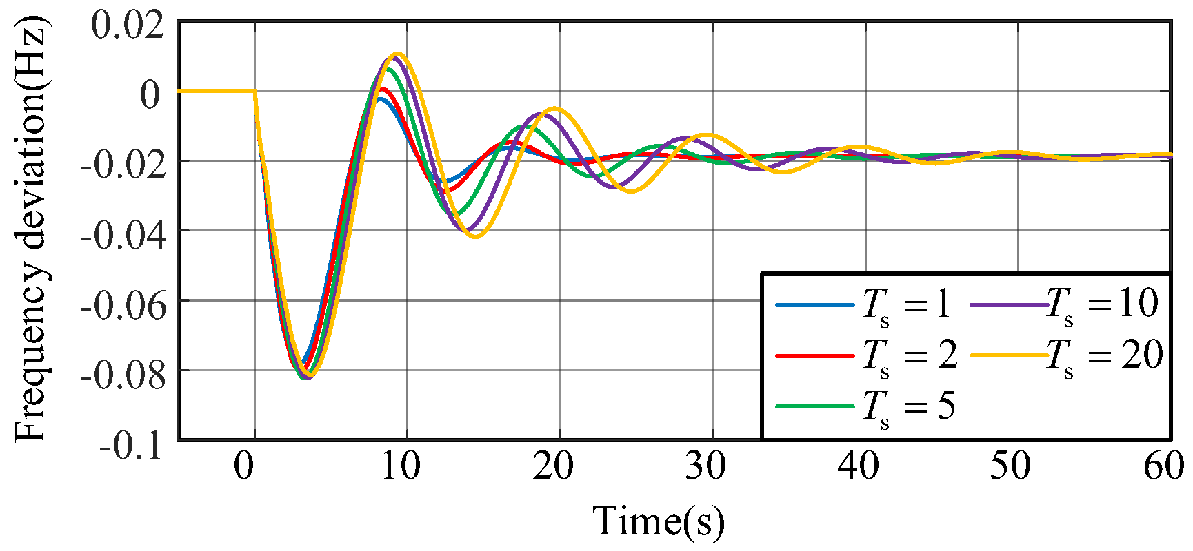
Figure 13 shows the simulation results when the time constant or the gain of the df/dt controller changes. It can be seen that the system is more stable with a larger time constant Ts and a smaller virtual inertia kf.
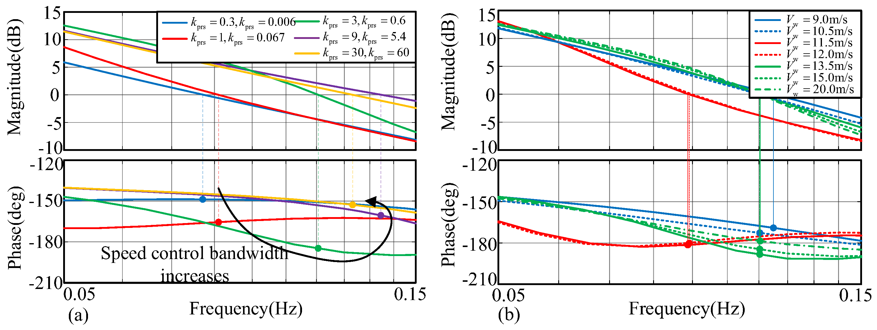
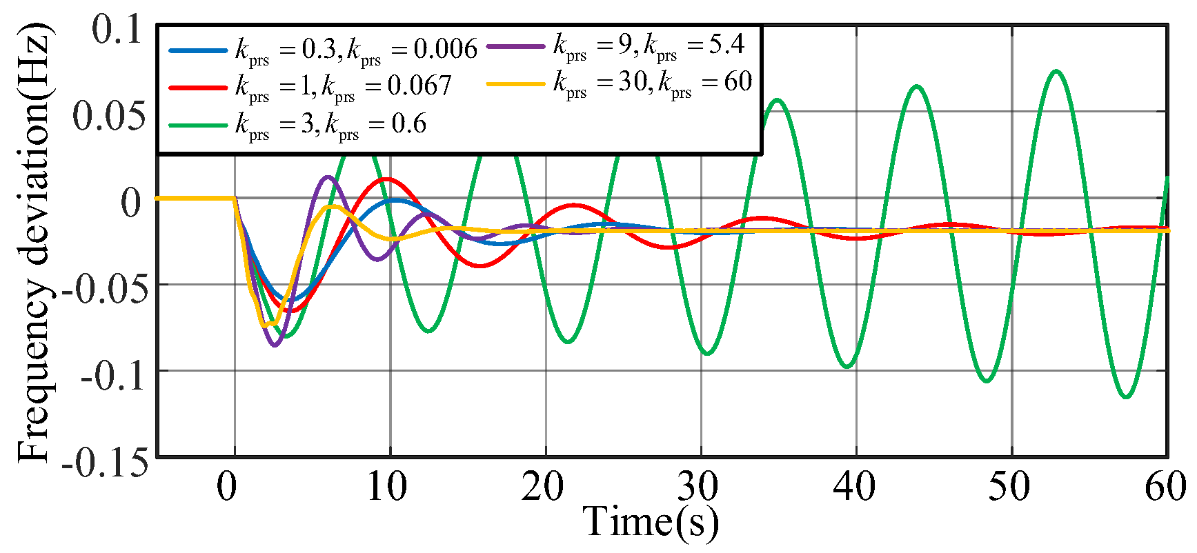
Figure 14 shows that the system becomes more unstable and then more stable when the bandwidth of the speed control increases.
Figure 15 shows the simulation results when the wind farm operates within different regions. When the wind speed increases, the power output of the wind farm is larger, and the system is more unstable, although the equivalent inertia of the DFIG varies.
Figure 16 illustrates that the system becomes more stable when the time constant of the low-pass filter of the MPPT increases.
When the pitch control parameter kpp increases, the system becomes more stable, as shown in Figure 17.
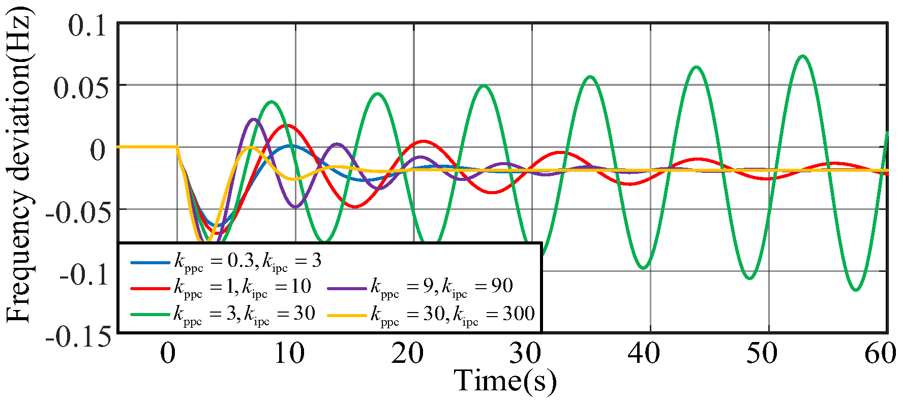
The influence of the bandwidth on pitch compensation control is shown in Figure 18. When the bandwidth increases, the system first becomes more unstable and then more stable.
The simulations above coincide with the analysis in Section 3, implying that the frequency domain analyses are correct.
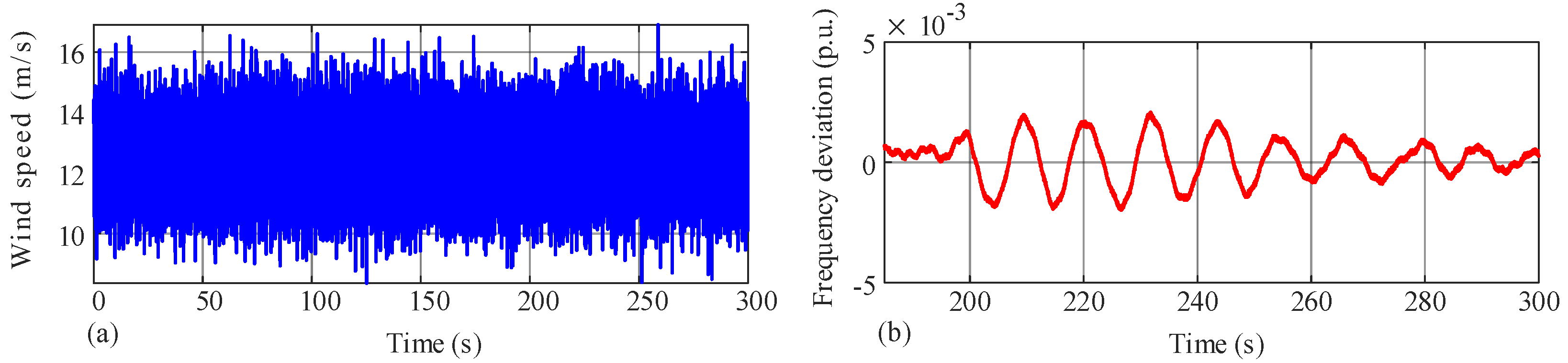
In reality, the wind speed is not constant. To simulate this effect on stability, the wind speed model is represented as follows:
V wind t = v average + v p sin ω wind t + v random
where vaverage = 12.5 m/s, vp = 0.5 m/s, ωwind = π rad/s, and vrandom is represented by a Gaussian-distributed random signal whose variance equals 1. A small load disturbance is added at t = 200 s, and the wind speed and system frequency response are shown in Figure 19. With the wind speed changing, the oscillation does not converge or diverge fast enough; thus, in the long period, the waveform is similar to an unattenuated oscillation.
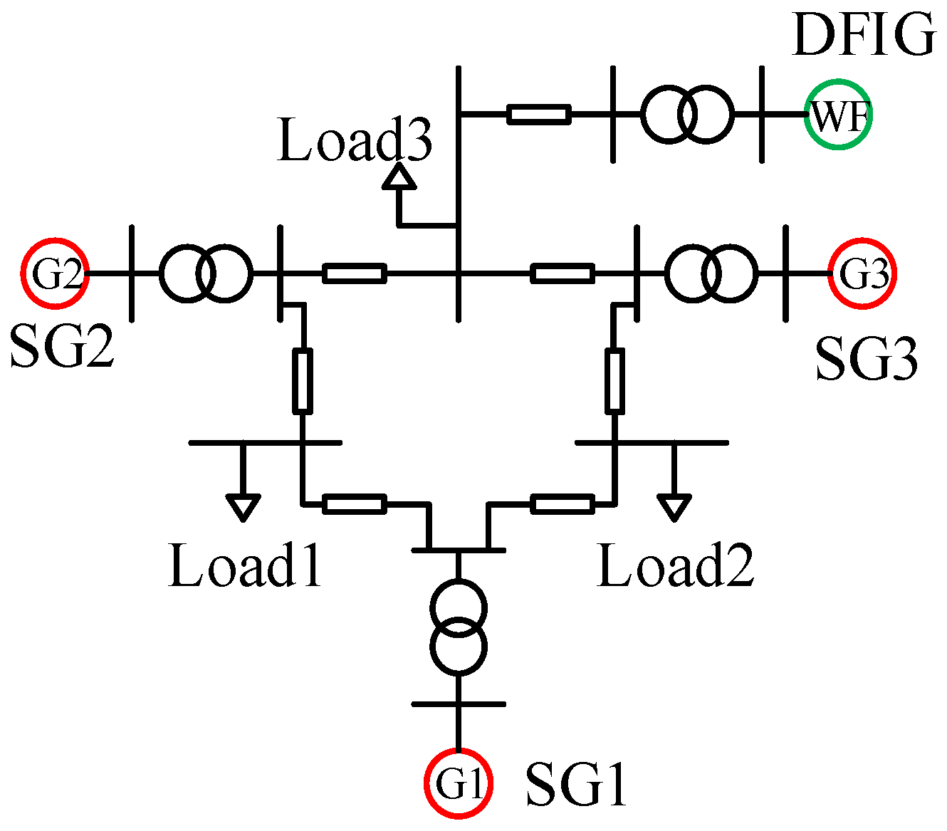
To explore whether the ultra-low frequency oscillation may exist in other systems, the four-machine, two-area system is utilized, where the steam turbines in the left area are replaced by two DFIGs. The system topology is shown in Figure 20. At t = 150 s, a load disturbance is added to Load 1, and the simulation result is shown in Figure 21. It can be seen that although the simulation system has changed, this phenomenon still exists.

5. Conclusions

Various kinds of new oscillation instability issues occur when the capacity of REG increases. This paper focused on the ultra-low frequency oscillation risk in thermal power generation systems and discovered that DFIGs with df/dt virtual inertia controllers can induce this problem, which has not been reported or studied. By deriving the motion equation model of the DFIG, it was shown that the negative phase characteristic introduced by the equivalent inertia of the DFIG can reduce the phase margin of the entire system within the ultra-low frequency band, making the system lose stability more easily. Subsequently, key factors that influence the stability were analyzed through frequency domain characteristic analysis, depicting influencing trends. Especially, it should be noticed that the increase in the virtual inertia and the decrease in its time constant deteriorate the stability, creating a conflict between providing a fast inertial response and the stability requirement. Finally, time-domain simulations verified the consistency between electromagnetic transient model dynamics and frequency domain analyses.
Since the ULFO is introduced by the negative phase of the equivalent inertia of the DFIG, it is important to develop a method to mitigate this effect while preserving the ability of the fast inertial response. Future studies may include reshaping the equivalent inertia to satisfy both requirements or designing effective controllers for oscillation damping.

Author Contributions

Conceptualization, W.H. (Wei He); methodology, X.Z. and W.H. (Wei He); formal analysis, X.Z., Y.L. and Y.F.; investigation, Y.F.; writing—original draft, Y.L. and W.H. (Wei He); project administration, W.H. (Wei Huang), S.Z. and X.L.; funding acquisition, W.H. (Wei Huang). All authors have read and agreed to the published version of the manuscript.

Funding

This research was funded by the Technology Project of China Southern Power Grid. [Project number: YNKJXM2022036]. And The APC was funded by the Technology Project of China Southern Power Grid. [Project number: YNKJXM2022036].

Data Availability Statement

The original contributions presented in this study are included in the article. Further inquiries can be directed to the corresponding author.

Conflicts of Interest

Author Wei Huang is employed by the Kunming Power Supply Bureau of Yunnan Power Grid Company Limited. Suwei Zhai and Xuegang Lu are employed by Yunnan Electric Power Dispatching and Control Center. The remaining authors declare that the research was conducted in the absence of any commercial or financial relationships that could be construed as a potential conflict of interest. The company had no role in the design of the study; in the collection, analyses, or interpretation of data; in the writing of the manuscript, or in the decision to publish the results.

Nomenclature

RPrimary frequency regulation coefficient
T1, T3Control time constant of the governor and the servo mechanism time constant
TCH, Trh, TCOSteam volume effect, reheater, and cross tube time constant
FHP, FIP, FLPHigh-, intermediate-, and low-pressure cylinder power proportional coefficient
λNatural overshoot coefficient
HSGInertia time constant of the rotor
JSGInertia time constant of the DFIG rotor
ωrRotor speed of the DFIG
ωpll, θpllFrequency and phase of the phase-locked loop
kppll, kipllProportional and integral parameters of the phase-locked loop
TsMPPT time constant
a, b, cMPPT control parameters
kf, TfGain and time constant of the virtual inertia control
kprs, kirsProportional and integral parameters of the speed controller
kpp, kipProportional and integral parameters of the pitch controller
kpc, kicProportional and integral parameters of the pitch compensation controller
TpTime constant of the low-pass filter for pitch and pitch compensation controllers
Ls, LmStator and mutual inductance of the DFIG
UtTerminal voltage of the DFIG
ω0Nominal angular frequency
kVIntegral parameter of the terminal voltage control
E, θAmplitude and phase of the internal voltage
ird, irqdq axis components of the rotor current of the DFIG
pComponents in the phase-locked loop coordinate
ωbNominal angular frequency
refReference value
sLaplacian operator

References

  1. Mo, W.; Chen, Y.; Chen, H.; Liu, Y.; Zhang, Y.; Hou, J.; Gao, Q.; Li, C. Analysis and Measures of Ultralow-Frequency Oscillations in a Large-Scale Hydropower Transmission System. IEEE J. Emerg. Sel. Top. Power Electron. 2018, 6, 1077–1085. [Google Scholar] [CrossRef]
  2. Hovey, L.M. Optimum Adjustment of Hydro Governors on Manitoba Hydro System. Trans. Am. Inst. Electr. Eng. Part III Power Appar. Syst. 1962, 81, 581–586. [Google Scholar] [CrossRef]
  3. Seppanen, J.; Lehtonen, M.; Kuivaniemi, M.; Haarla, L. Long Term Characteristics of Ultra Low Frequency Oscillations in the Nordic Power System. In Proceedings of the 2022 IEEE PES Innovative Smart Grid Technologies Conference Europe (ISGT-Europe), Novi Sad, Serbia, 10–12 October 2022; pp. 1–5. [Google Scholar]
  4. Wang, P.; Liu, T.; Wang, S.; Jiang, Q.; Yang, L.; Li, B. Small-signal Model and Influencing Factors Analysis of Ultra-low Frequency Oscillation in Hydropower Unit. Proc. CSEE 2020, 40, 5942–5954. (In Chinese) [Google Scholar]
  5. Su, Y.; Liu, T.; Li, B.; Jiang, Q.; Han, X.; Chen, G. Mechanism Analysis of Ultra-low Frequency Oscillation and Parameter Optimization of Hydro Turbine Governor. Power Syst. Technol. 2020, 44, 1008–1016. (In Chinese) [Google Scholar]
  6. Gao, Q.; Liu, Q.; Chen, Y.; Li, C.; Zhang, Y.; Du, X. Influence of Different Deadbands on the Frequency Stability. Power Syst. Technol. 2020, 44, 3575–3581. (In Chinese) [Google Scholar]
  7. Jiang, C.; Zhou, J.; Shi, P.; Li, S.; Huang, W.; Gan, D. Multi-objective Robust design of Hydro-turbine Governor Parameter, Considering Ultra-low Frequency Oscillation. Autom. Electr. Power Syst. 2019, 43, 125–131+147. (In Chinese) [Google Scholar]
  8. Zhang, J.; Shi, X.; Chen, G.; Zhou, J.; Cai, D.; Cai, W.; Jiang, C.; Zhao, Y. Simulation Test on Additional Damping Control of Hydropower Unit Governor. South. Power Syst. Technol. 2019, 13, 24–28. (In Chinese) [Google Scholar] [CrossRef]
  9. Yi, J.; Zhang, G.; Liu, M.; Zhang, X.; Zhang, P.; Teng, Y. Control Mechanism and Strategy Verification of Stabilizer for Suppressing Ultra-low Frequency Oscillation. Autom. Electr. Power Syst. 2020, 44, 192–199. (In Chinese) [Google Scholar]
  10. Liu, Q.; Chen, G.; Liu, B.; Zhang, Y.; Liu, C.; Zeng, Z.; Fan, C.; Han, X. Emergency Control Strategy of Ultra-low Frequency Oscillations Based on WAMS. In Proceedings of the 2019 IEEE Innovative Smart Grid Technologies—Asia (ISGT Asia), Chengdu, China, 21–24 May 2019; pp. 296–301. [Google Scholar]
  11. Zhang, G.; Hu, W.; Cao, D.; Huang, Q.; Yi, J.; Chen, Z.; Blaabjerg, F. Deep Reinforcement Learning-Based Approach for Proportional Resonance Power System Stabilizer to Prevent Ultra-Low-Frequency Oscillations. IEEE Trans. Smart Grid 2020, 11, 5260–5272. [Google Scholar] [CrossRef]
  12. Zhou, X.; He, P.; He, X. Research on Optimization of Damping Control Parameters for Suppressing Ultra-low Frequency Oscillation of Hydro-Generator Units. Yunnan Electr. Power 2019, 47, 107–113. (In Chinese) [Google Scholar]
  13. Liu, L.; Luo, X.; Xiong, L.; Guo, J.; Liu, X.; Liu, Y. Preset Power Based Droop Control for Improving Primary Frequency Regulation of Inverters Under Large Disturbances. IEEE Trans. Power Electron. 2025, 40, 9153–9166. [Google Scholar] [CrossRef]
  14. Jiang, C.; Zhou, J.; Shi, P.; Huang, W.; Gan, D. Ultra-low Frequency Oscillation Analysis and Robust Fixed Order Control Design. Int. J. Electr. Power Energy Syst. 2019, 104, 269–278. [Google Scholar] [CrossRef]
  15. Zhang, T.; Zhou, T.; Bu, J.; Chen, L.; Xu, Z. Influence Mechanism Analysis of Wind Power Integration on Ultra-low Frequency Oscillation Based on Comprehensive Inertial Control. In Proceedings of the 2021 IEEE Sustainable Power and Energy Conference, Nanjing, China, 23–25 December 2021; pp. 383–389. [Google Scholar]
  16. He, T.; Shu, H.; Li, S.; Wu, S.; Wan, L.; Dai, J. Analysis of the influence of wind power participating in frequency regulation on the ultra-low frequency oscillation of power system. Renew. Energy Resour. 2023, 41, 1113–1121. [Google Scholar]
  17. Wang, S.; Xu, Y.; Wu, X.; Wang, J.; Chen, G.; Zeng, X. Ultra-Low Frequency Oscillation Damping Control Method for Hydro-Photovoltaic Integrated Systems. IEEE Trans. Power Electron. 2025, 40, 2397–2418. [Google Scholar] [CrossRef]
  18. Australian Energy Market Commission. Frequency Control Frameworks Review. 2018. Available online: https://www.aemc.gov.au/sites/default/files/2018-07/Final%20report.pdf (accessed on 27 July 2021).
  19. EirGrid; University College Cork. Analysis, Monitoring and Mitigation of Common Mode Oscillations on the Power System of Ireland and Northern Ireland. 2020. Available online: https://e-cigre.org/publication/SESSION2020_C4-107 (accessed on 30 July 2021).
  20. Clark, K.; Miller, N.W.; Sanchez-Gasca, J. Modeling of GE Wind Turbine Generators for Grid Studies; G.E.: New York, NY, USA, 2010. [Google Scholar]
  21. He, W.; Yuan, X.; Hu, J. Inertia provision and estimation of PLL-based DFIG wind turbines. IEEE Trans. Power Syst. 2017, 32, 510–521. [Google Scholar] [CrossRef]
  22. Sun, L.; Zhao, X. Impacts of phase-locked loop and reactive power control on inertia provision by DFIG wind turbine. IEEE Trans. Energy Convers. 2019, 37, 109–119. [Google Scholar] [CrossRef]
  23. Huang, H.; Ju, P.; Jin, Y.; Yuan, X.; Qin, C.; Pan, X.; Zang, X. Generic system frequency response model for power grids with different generations. IEEE Access 2020, 8, 14314–14321. [Google Scholar] [CrossRef]
  24. Morren, J.; Pierik, J.; de Haan, S.W.H. Inertial response of variable speed wind turbines. Electr. Power Syst. Res. 2006, 76, 980–987. [Google Scholar] [CrossRef]
Figure 1. The structure of the governor and the steam turbine: (a) governor; (b) steam turbine.
Processes 13 01368 g001
Figure 2. Linearized model of the DFIG.
Processes 13 01368 g002
Figure 3. Motion equation model of the DFIG.
Processes 13 01368 g003
Figure 4. Verification of the motion equation: (a) test system; (b) active power deviation; (c) rotor speed deviation; and (d) terminal voltage deviation.
Processes 13 01368 g004
Figure 5. The analytical model of ULFO.
Processes 13 01368 g005
Figure 6. Approximate relationship between the unbalanced active power and the internal voltage phase.
Processes 13 01368 g006
Figure 7. The impact of the equivalent inertia of the wind turbine on system inertia.
Processes 13 01368 g007
Figure 8. The extended three-machine, nine-bus system.
Processes 13 01368 g008
Figure 9. The impact of df/dt parameters on stability: (a) time constant; (b) virtual inertia.
Processes 13 01368 g009
Figure 10. The impact of (a) speed control bandwidth and (b) wind speed on system stability.
Processes 13 01368 g010
Figure 11. The impact of (a) MPPT time constant and (b) pitch control parameter on system stability.
Processes 13 01368 g011
Figure 12. The impact of pitch compensation parameters on system stability.
Processes 13 01368 g012
Figure 13. Simulation results when (a) time constant and (b) virtual inertia changes.
Processes 13 01368 g013
Figure 14. Simulation results when the speed control bandwidth changes.
Processes 13 01368 g014
Figure 15. Simulation results of the wind farm within different operation regions.
Processes 13 01368 g015
Figure 16. Simulation results when the time constant of the MPPT control changes.
Processes 13 01368 g016
Figure 17. Simulation results when the pitch control parameter changes.
Processes 13 01368 g017
Figure 18. Simulation results when the bandwidth of the pitch compensation control changes.
Processes 13 01368 g018
Figure 19. Response under varying wind speed: (a) wind speed waveform; (b) system frequency response.
Processes 13 01368 g019
Figure 20. The four-machine, two-area system.
Processes 13 01368 g020
Figure 21. System frequency response in the four-machine, two-area system.
Processes 13 01368 g021
Table 1. Damping ratio and oscillation frequency with different Tf.
TfDamping RatioFrequency (Hz)
200.6130.0892
100.5490.0873
50.4280.0845
20.2180.0838
10.1050.0861
0.1−0.01290.0912
Table 2. Damping ratio and oscillation frequency with different kf.
kfDamping RatioFrequency (Hz)
50.2080.122
100.1060.106
20−0.01290.0912
Table 3. Damping ratio and oscillation frequency with different speed control bandwidth.
kprs, kirsDamping RatioFrequency (Hz)
0.3, 0.0060.4080.0848
1, 0.0670.2850.0795
3, 0.6−0.01290.0912
9, 5.40.2780.128
30, 600.350.147
Table 4. Damping ratio and oscillation frequency with different wind speeds.
VwDamping RatioFrequency (Hz)
90.09470.0998
10.50.09210.0923
11.50.1590.0734
120.1930.0737
13.5−0.01290.0912
150.03110.0874
200.06840.0890
Table 5. Damping ratio and oscillation frequency with different Ts.
TsDamping RatioFrequency (Hz)
10.2510.113
20.180.11
50.09470.0998
100.06740.0914
200.06570.0853
Table 6. Damping ratio and oscillation frequency with different kpp.
KppDamping RatioFrequency (Hz)
100−0.06030.0913
150−0.01290.0912
2000.07530.0823
Table 7. Damping ratio and oscillation frequency with different pitch compensation control bandwidth.
kppc, kipcDamping RatioFrequency (Hz)
0.3, 30.3420.0829
1, 100.2640.0772
3, 30−0.01290.0912
9, 900.0270.139
30, 3000.1560.152
Disclaimer/Publisher’s Note: The statements, opinions and data contained in all publications are solely those of the individual author(s) and contributor(s) and not of MDPI and/or the editor(s). MDPI and/or the editor(s) disclaim responsibility for any injury to people or property resulting from any ideas, methods, instructions or products referred to in the content.

