
Study of the Scale-Up Method and Dynamic Performance of the Forced-Air Self-Aspirating Flotation Machine


Abstract
1. Introduction
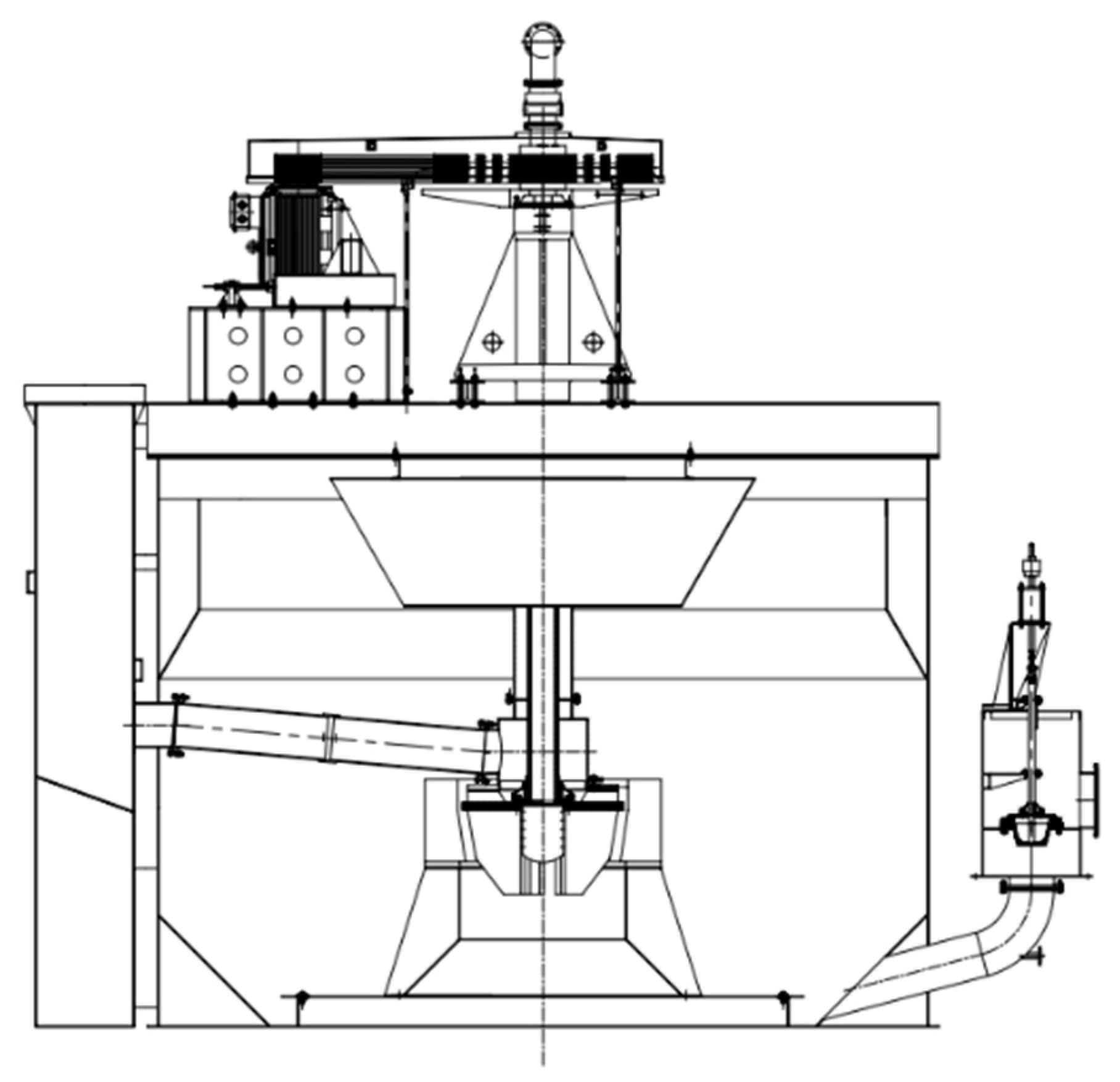
2. Forced-Air Self-Aspirating Flotation Machine
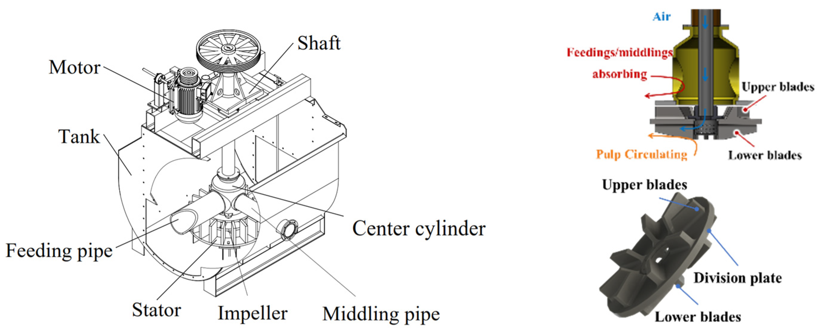
2.1. Conventional Forced-Air Self-Aspirating Flotation Machine
2.2. Methods
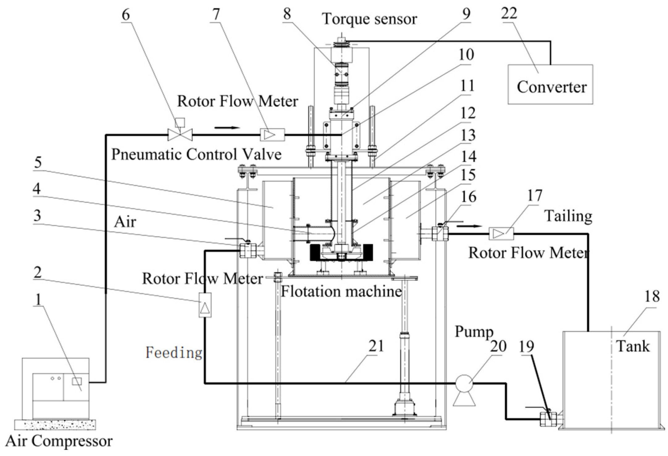
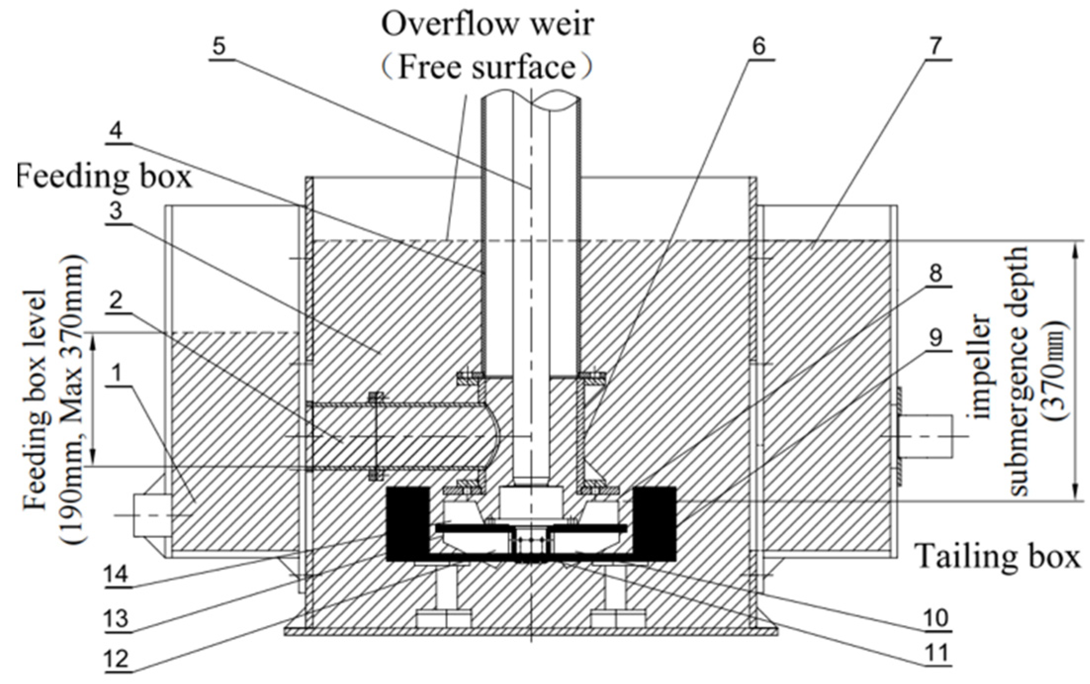
2.2.1. Experiment System of the Forced-Air Self-Aspirating Flotation Machine
2.2.2. Industrial Experiment System of the Forced-Air Self-Aspirating Flotation Machine
3. Scale-Up Challenges for Forced-Air Self-Aspirating Flotation Machines
3.1. Influencing Factors of Pulp Suction Capacity and Power Consumption in Flotation Machines
3.2. Scale-Up Limitations in Forced-Air Self-Aspirating Flotation Machines
4. Scale-Up Design Method of Large-Scale Forced-Air Self-Aspirating Flotation Machines
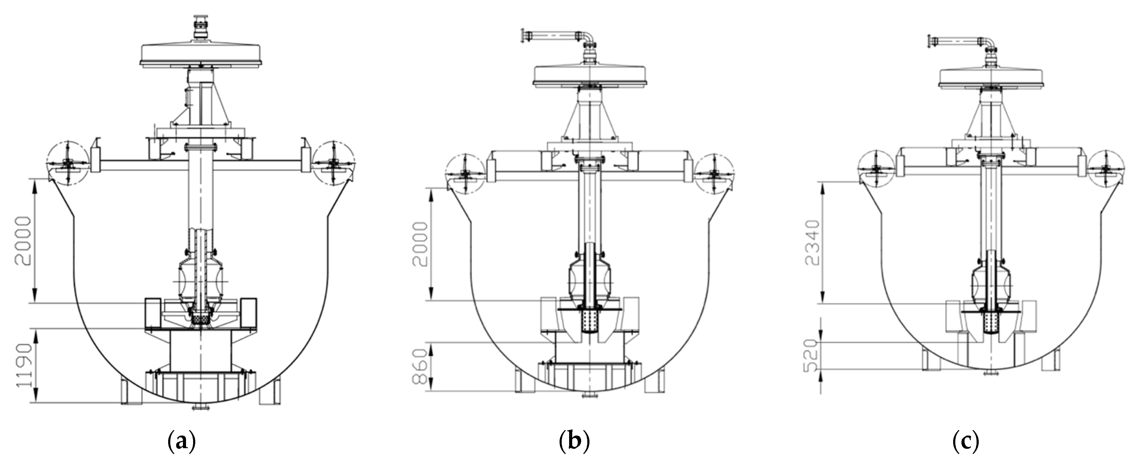
4.1. Large-Scale Design Program
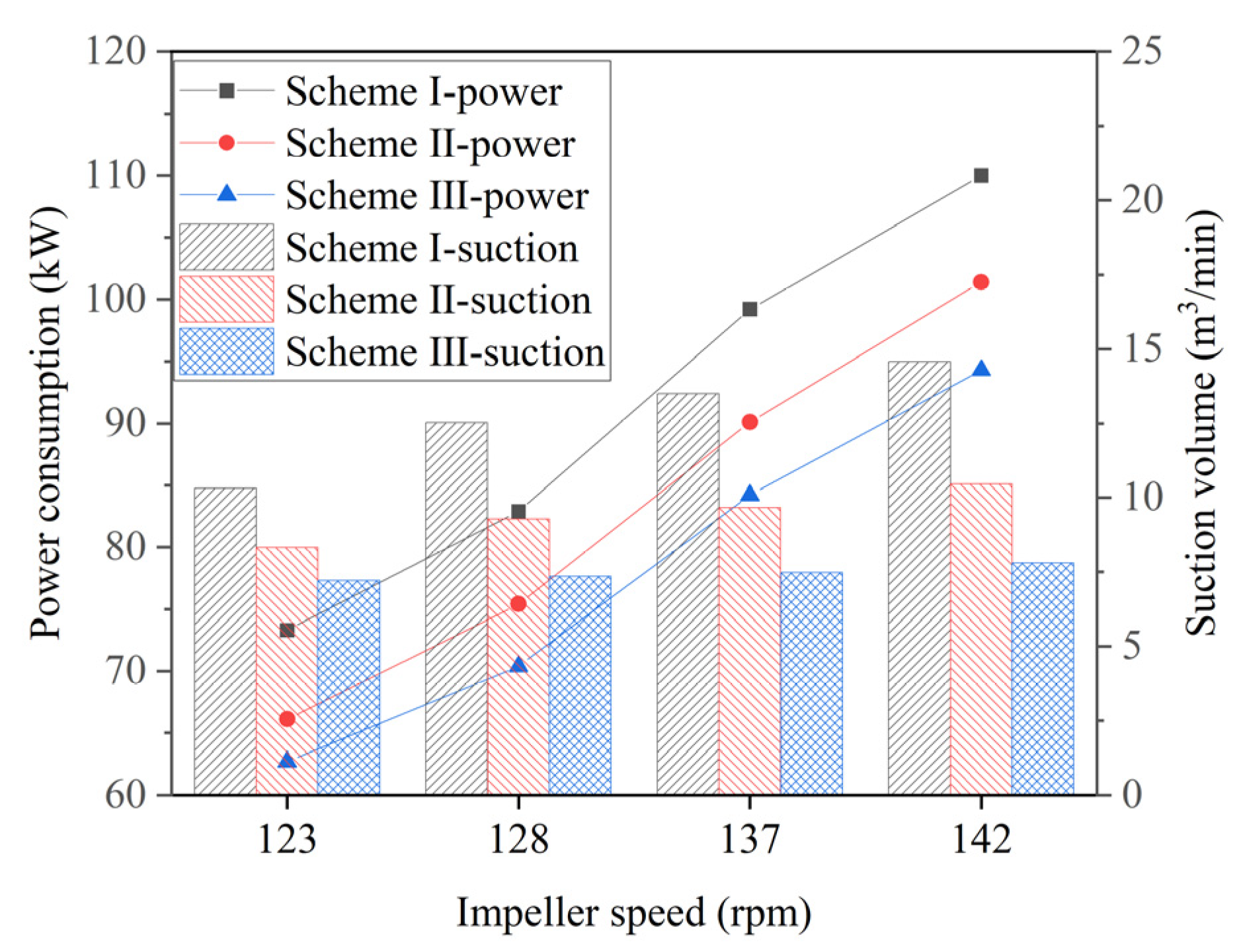
4.2. Verification of the Design Scheme
4.3. Design and Scale-Up Method of the Forced-Air Self-Aspirating Flotation Machine
5. The Hydrodynamic Performance of Large-Scale Forced-Air Self-Aspirating Flotation Machines
5.1. Models
5.2. Hydrodynamic Performance of the Forced-Air Self-Aspirating Flotation Machine
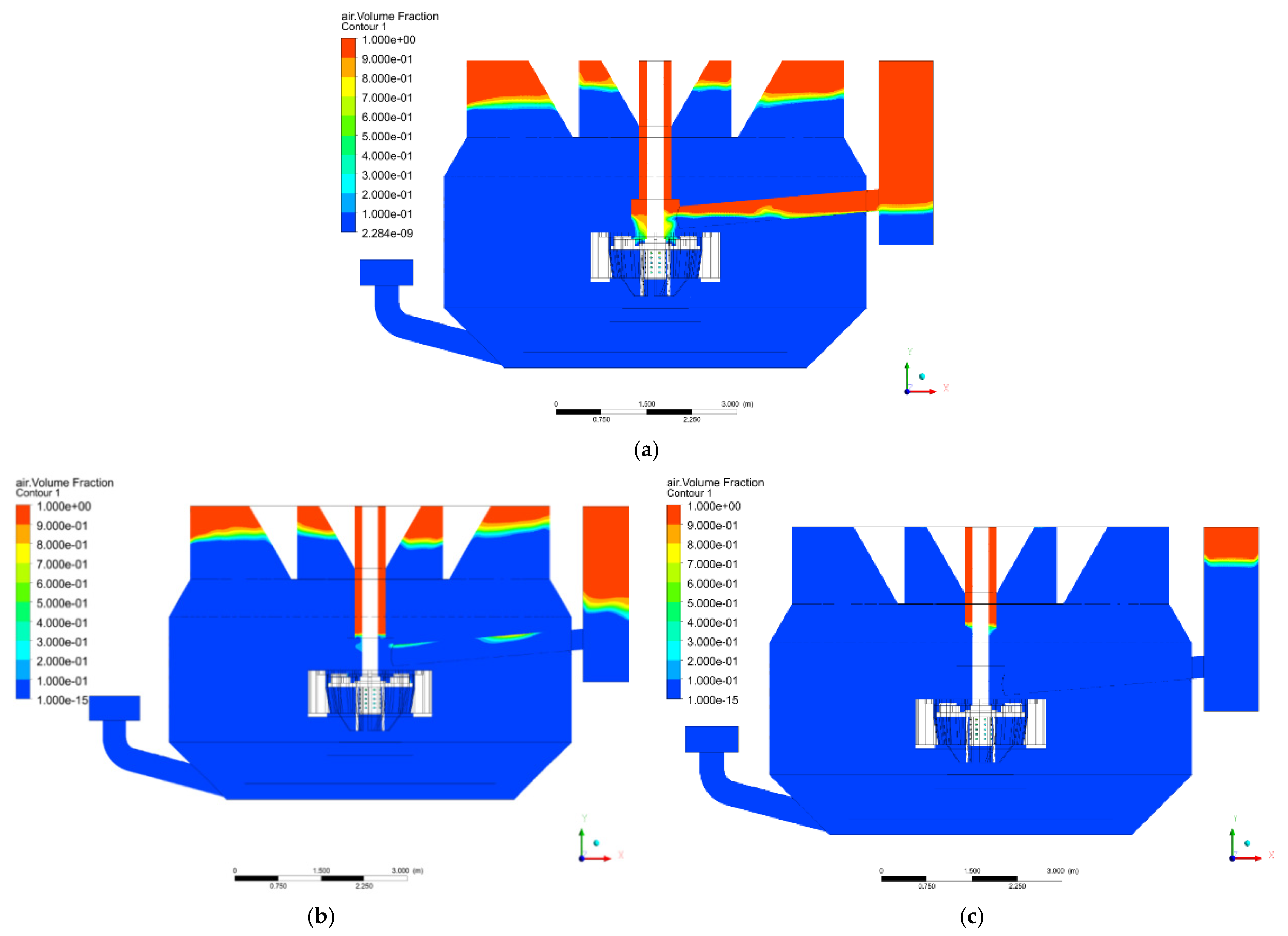
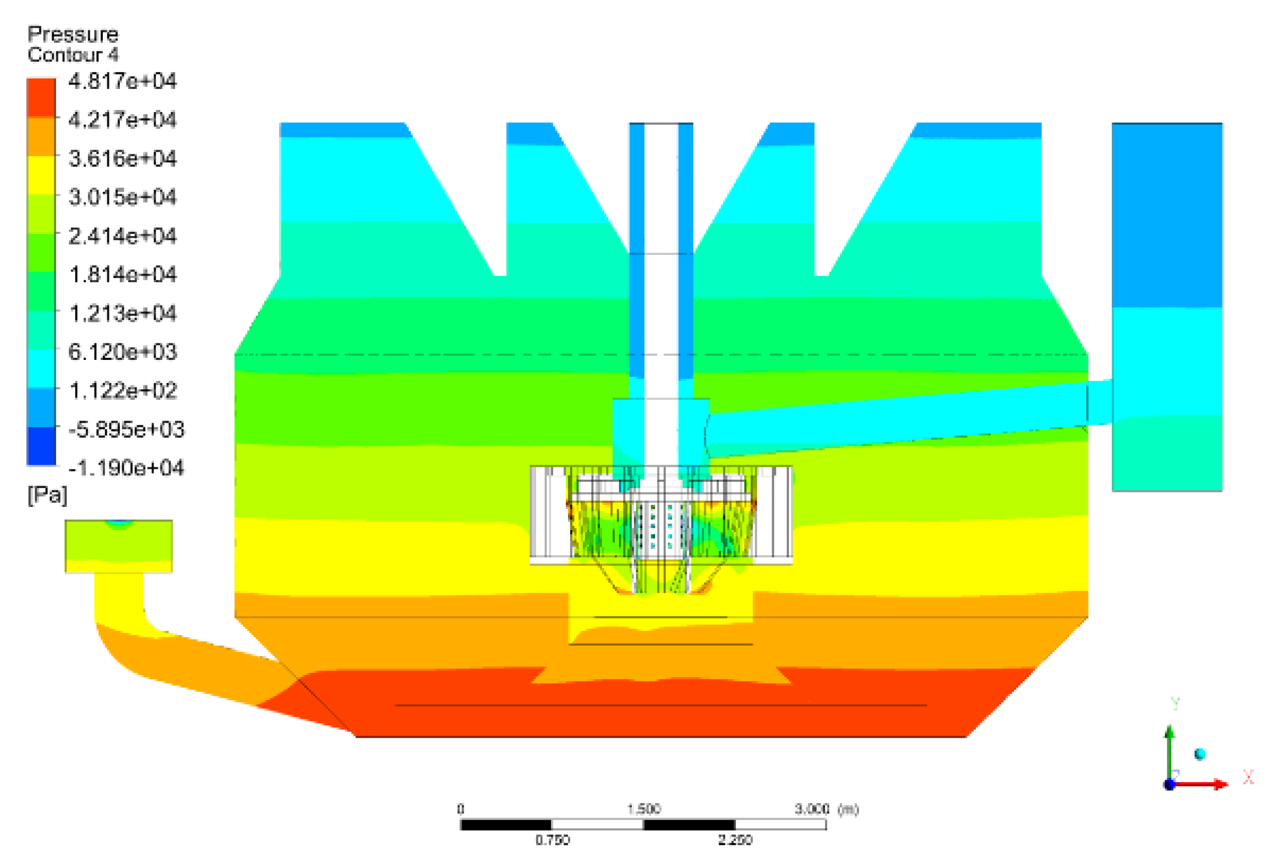
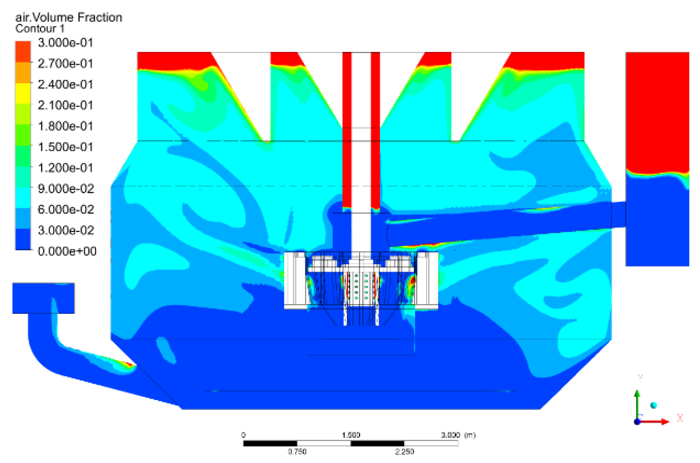
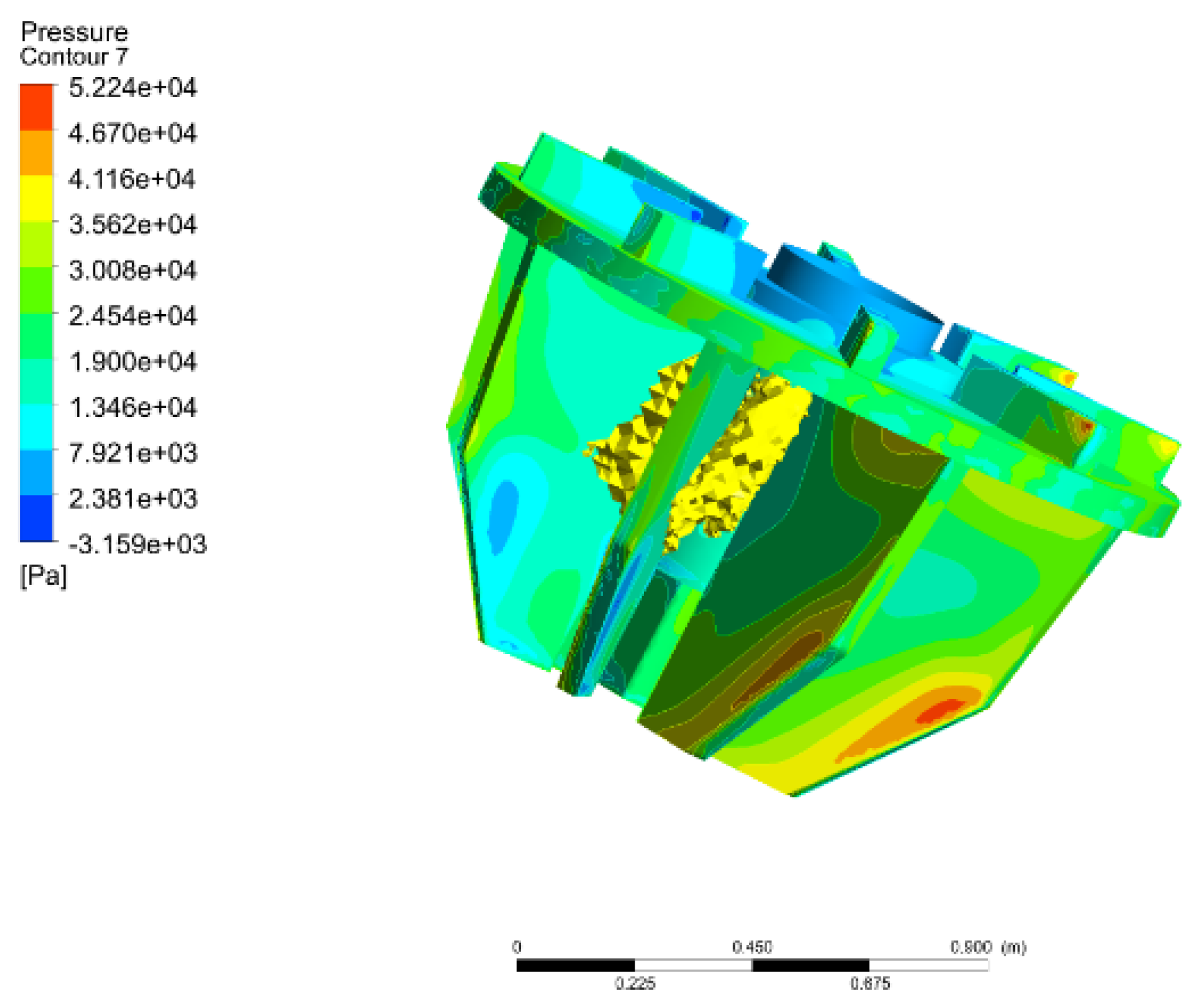
5.2.1. Suction Process of the Large-Scale Forced-Air Self-Aspirating Flotation Machine
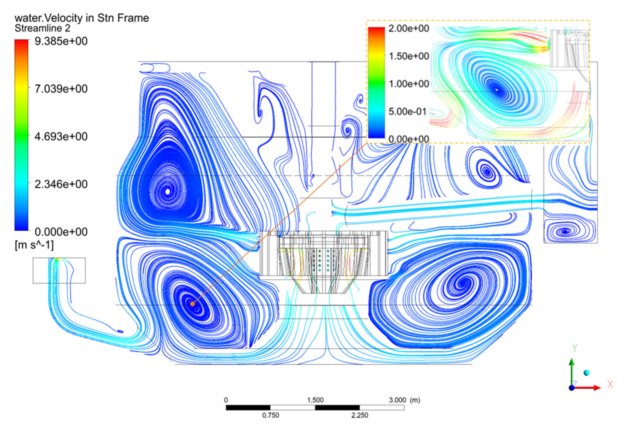
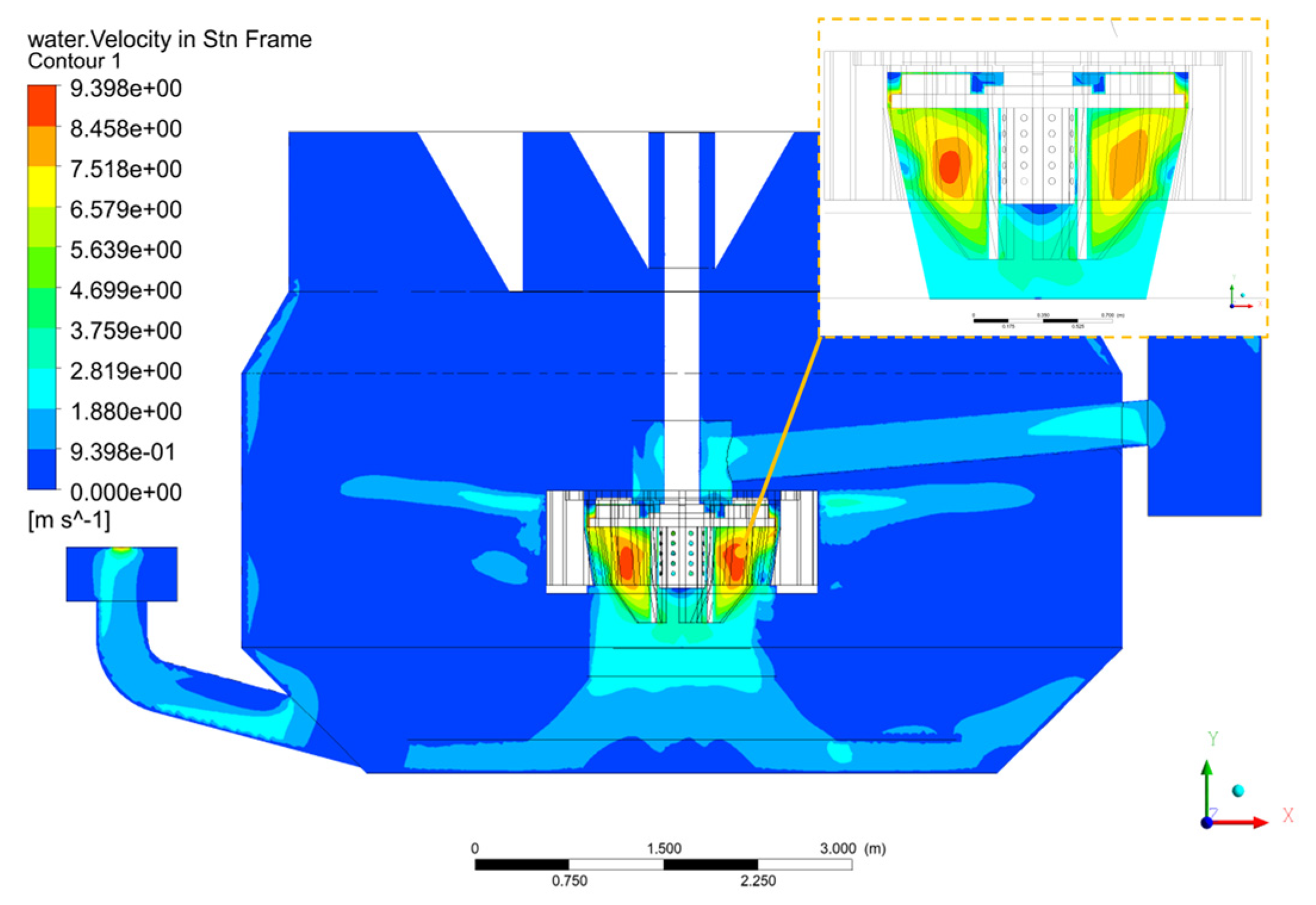
5.2.2. Flow Pattern of the Large-Scale Forced-Air Self-Aspirating Flotation Machine
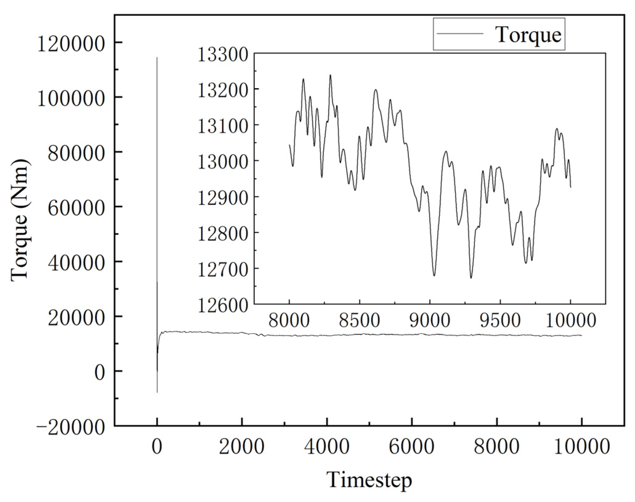
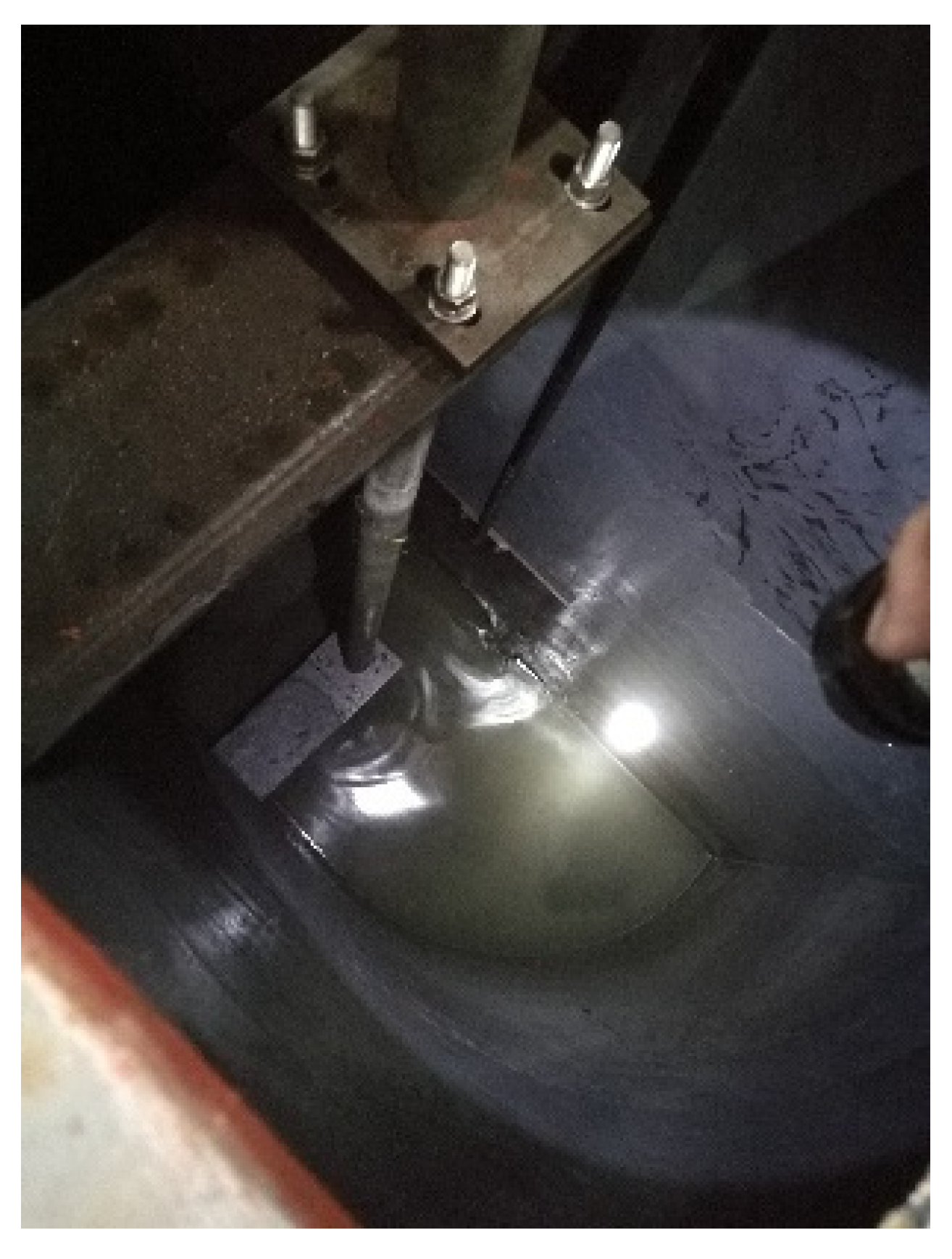
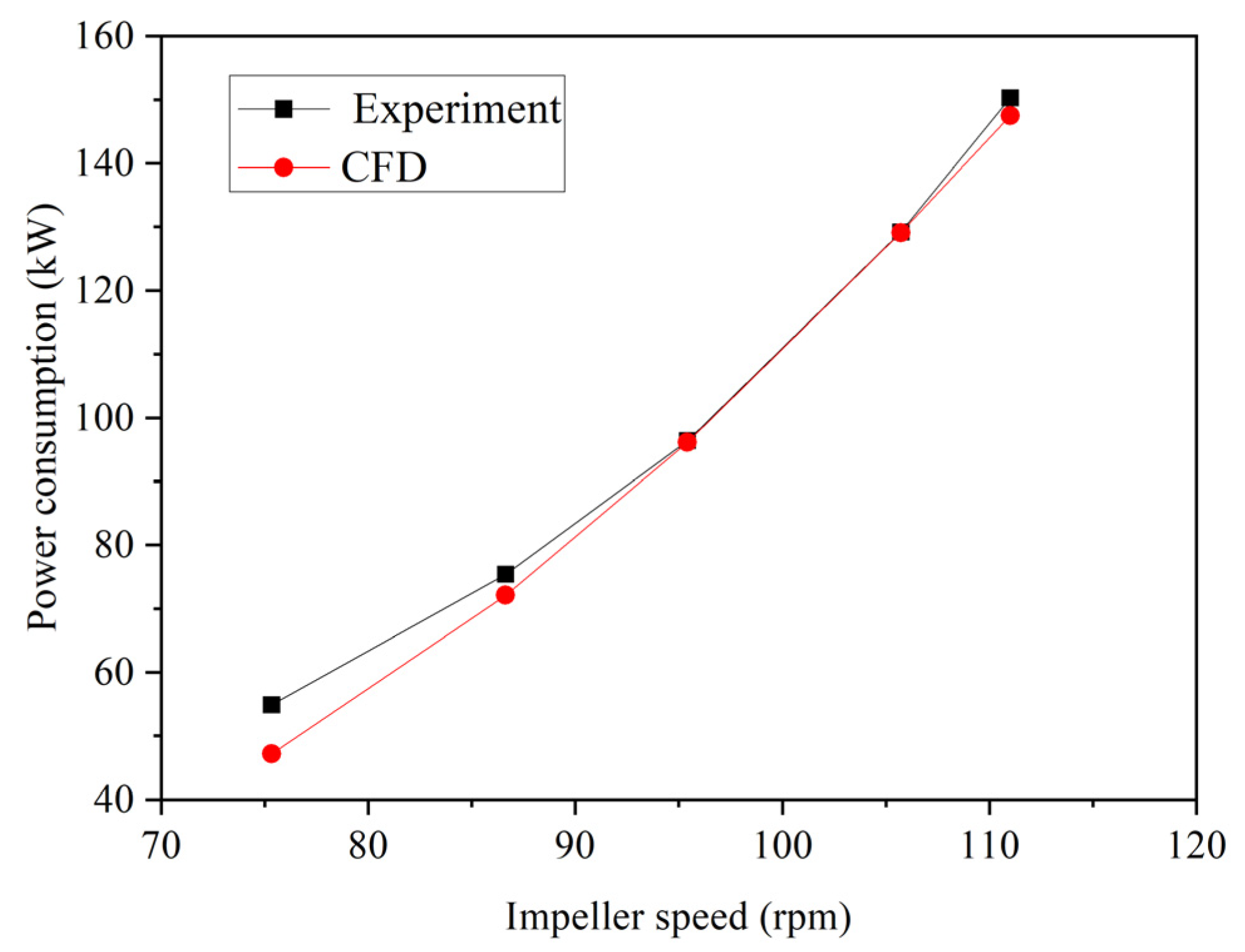
6. Dynamic Performance Testing and Validation of the Scale-Up Method
7. Conclusions
- (1)
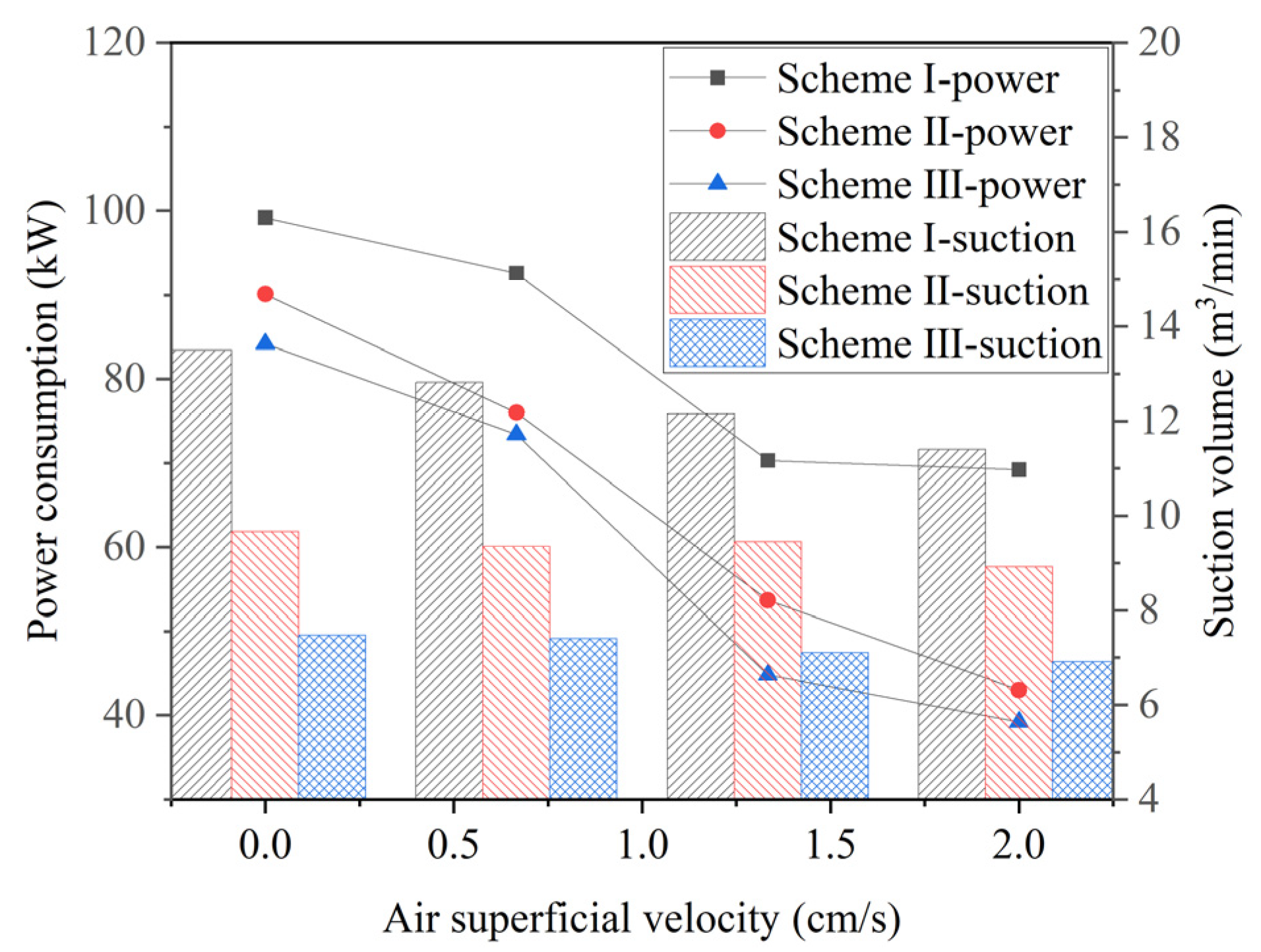
- Speed, air superficial velocity, feeding box level, and impeller submergence depth are the key factors influencing pulp suction capacity and power consumption. As the impeller submergence depth increases, the pulp suction capacity decreases, while the power consumption rises, indicating a significant increase in pulp suction resistance. Since the submergence depth inevitably increases with the scale-up of flotation machines using conventional designs, this becomes a core challenge in scaling up forced-air self-aspirating flotation machines.
- (2)
- An innovative design scheme for a large-scale forced-air self-aspirating flotation machine was developed, featuring an impeller–stator system positioned in the middle of the tank. By placing the impeller–stator system centrally, the issue of the impeller moving farther from the overflow weir during scale-up is eliminated, preventing a dramatic increase in pulp suction resistance as the equipment size increases.
- (3)
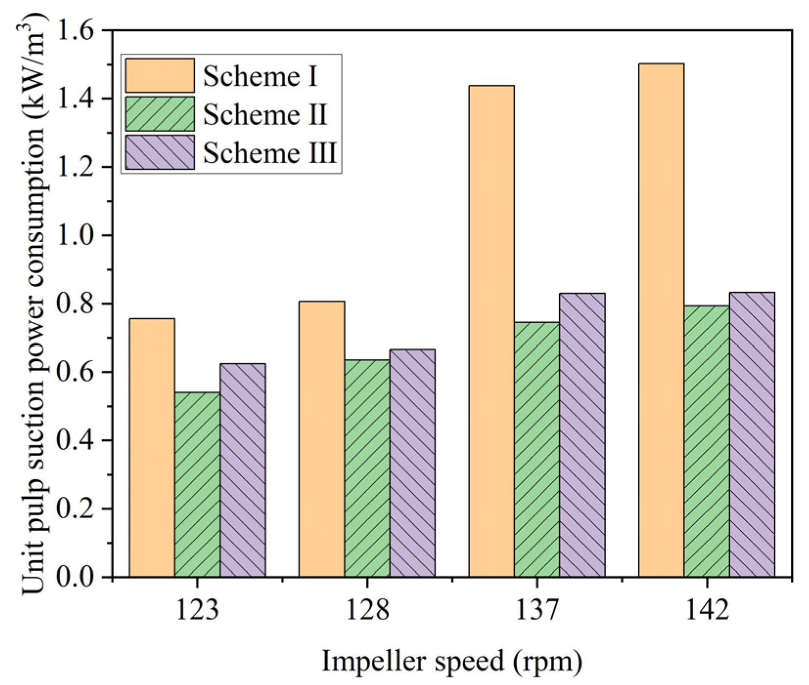
- The new impeller with the middle placement design demonstrates superior separation performance and a favorable balance between pulp suction capacity and power consumption. The industrial trial results confirm that the developed new impeller with the middle placement design significantly reduces power consumption and enhances separation performance, making it a viable design solution for large-scale forced-air self-aspirating flotation machines.
- (4)
- The independent designs of the pulp suction capacity of the upper blades and the pulp circulation capacity of the lower blades were further developed. This approach addresses the challenges of high power consumption and poor metallurgical performances in large-scale forced-air self-aspirating flotation machines, ensuring a more efficient and effective flotation process.
- (5)
- A design method and scale-up method for large-scale forced-air self-aspirating flotation machines were established. Core hydrodynamic performance parameters, including power consumption, pulp suction capacity, and circulation capacity, were predicted through CFD simulation, and the feasibility and accuracy of the scale-up method were successfully verified.
- (6)
- The largest forced-air self-pumping flotation machine, with a volume of 160 m3, was developed and successfully applied in engineering. An industrial test study confirmed that the flotation machine effectively achieved pulp suction while maintaining power consumption that is comparable to or only slightly higher than that of an air-forced flotation machine. Additionally, good metallurgical performance was verified through industrial testing. Therefore, this study demonstrates that the developed flotation machine successfully meets the requirements for a horizontal configuration in large-scale flotation circuits.
Author Contributions
Funding
Data Availability Statement
Acknowledgments
Conflicts of Interest
References
- Chen, J.; Zhu, Y. Study of semi-constrained properties of metal ions on mineral surface of flotation system. J. China Univ. Min. Technol. 2021, 50, 1181–1188. [Google Scholar]
- Wang, Z.; Zhang, M.; Fan, X.; Chen, F.; Han, D. Research on fluid dynamics performance of air forced & pulp induced flotation cell using numerical simulation. Nonferrous Met. (Miner. Process. Sect.) 2017, 127–131. [Google Scholar]
- Shen, Z. Theory and Technologies of Flotation Cells; Metallurgical Industrial Press: Beijing, China, 2012. [Google Scholar]
- Yu, Y.; Han, D.; Liu, Z. Analysis and application of flat lauout of flotation cells. Min. Metall. 2017, 26, 63–66. [Google Scholar]
- Shen, Z. Principles and Technologies of Flotation Machines; Springer: Berlin/Heidelberg, Germany, 2021. [Google Scholar]
- Han, S. Development and application of XJZ series mechanical stirring flotation machine. Met. Mine 1991, 56–58. [Google Scholar]
- Zhang, H.; Xie, B.; Liu, G. SF and JJF flotation machine combined unit. Nonferrous Met. (Miner. Process. Sect.) 1987, 38–41. [Google Scholar]
- Dong, G.; Liu, G.; Liu, L. Application of BF-T flotation machine to upgrading iron concentrate. Min. Metall. 2005, 4, 20–22. [Google Scholar]
- Wan, L. Study on the application of XCF, KYF and GF flotation units in bauxite production. Copp. Eng. 2019, 70–75. [Google Scholar]
- Wang, G. Development trend and development trend of foreign flotation machine. World Eng. Ind. 1990, 2–9. [Google Scholar]
- Shen, Z. Development of the XCF II and the combined flotation unit of XCF II/KYF II pneumatic-mechanical cells and the production practice. Nonferrous Metall. Equip. 2007, 21, 4–7. [Google Scholar]
- Shen, Z.; Zhang, M.; Shi, S.; Zhang, Y.; Duan, L. The scale-up and dynamics performance research of the air forced self pumping flotation cell. J. China Univ. Min. Technol. 2022, 51, 434–444. [Google Scholar] [CrossRef]
- Mesa, D.; Brito-Parada, P.R. Scale-up in froth flotation: A state-of-the-art review. Sep. Purif. Technol. 2019, 210, 950–962. [Google Scholar] [CrossRef]
- Vinnett, L.; Yianatos, J.; Díaz, F.; Hassanzadeh, A. Estimating effective volumes in industrial forced-air flotation cells. Miner. Eng. 2024, 211, 108678. [Google Scholar] [CrossRef]
- Wang, Z.; Chen, B.; Du, J.; Sheng, K.; Yan, S. Impeller Structure Improvement of XCF Flotation Machine Based on Simulation. Nonferrous Met. (Miner. Process. Sect.) 2023, 109–117. [Google Scholar]
- Sun, C.; Shi, S.; Han, D.; Zhang, Y.; Zhang, M.; Zhang, F. Zoning model of flotation kinetics process in air-forced mechanical agitator flotation machine. J. China Univ. Min. Technol. 2022, 51, 411–418. [Google Scholar] [CrossRef]
- Yianatos, J.; Vallejos, P. Challenges in flotation scale-up: The impact of flotation kinetics and froth transport. Miner. Eng. 2024, 207, 108541. [Google Scholar] [CrossRef]
- Romero, J. First Tank Cells of 630 m3 in operation at Buena Vista. In Proceedings of the 1st Flotation Symposium, Outotec Chile Customer Seminar, Santa Cruz, Chile, 4–5 October 2018. [Google Scholar]
- Shen, Z.; Zhang, M.; Fan, X.; Shi, S.; Han, D. Hydrodynamic and Flotation Kinetic Analysis of a Large Scale Mechanical Agitated Flotation Cell with the Typical Impeller and the Arc Impeller. Minerals 2019, 9, 79. [Google Scholar] [CrossRef]
- Shen, Z.; Chen, D.; Zhang, M.; Dong, G. Hydrodynamics analysis of a 680 M3 mechanical agitated flotation cell based on numerical simulation. In Proceedings of the 28th International Mineral Processing Congress, IMPC 2016, Quebec City, QC, Canada, 11–15 September 2016; Canadian Institute of Mining, Metallurgy and Petroleum: Westmount, QC, Canada, 2016. [Google Scholar]
- Lelinski, D.; Stevens, D.; Walker, M.; Weber, A. Metallurgical Performance of the 660 m3 SuperCell™ equipped with the nextSTEP™ Rotor and Stator. In Proceedings of the Flotation’17, Cape Town, South Africa, 13–16 November 2017; MEI: Cape Town, South Africa, 2017. [Google Scholar]
- Li, S.; Schwarz, M.P.; Yang, W.; Feng, Y.; Witt, P.; Sun, C. Experimental observations of bubble–particle collisional interaction relevant to froth flotation, and calculation of the associated forces. Miner. Eng. 2020, 151, 106335. [Google Scholar] [CrossRef]
- Nelson, M.G.; Lelinski, D. Hydrodynamic design of self-aerating flotation machines. Miner. Eng. 2000, 13, 991–998. [Google Scholar] [CrossRef]
- Gorain, B.K. Design, Operating Principles, and Optimization of Mechanical Flotation Cells. In Proceedings of the Froth Flotation: A Century of Innovation, Cape Town, CA, USA, 2007; SME Inc.: Wilmington, NC, USA, 2007. [Google Scholar]
- Zhang, M.; Shen, Z.; Fan, X.; Shi, S.; Yang, Y. Scale-up theory and technology of BGRIMM flotation cell. Nonferrous Met. (Miner. Process. Sect.) 2020, 98–104. [Google Scholar]
- Shi, S. The Flotation Dynamic Characteristics of Coarse Particle Minerals and the Structural Parameters Optimization of Large Flotation Machines. Ph.D. Thesis, University of Science and Technology Beijing, Beijing, China, 2020. [Google Scholar]
- Kelebek, S.; Yoruk, S. Bubble contact angle variation of sulphide minerals in relation to their self-induced flotation. Colloids Surf. A Physicochem. Eng. Asp. 2002, 196, 111–119. [Google Scholar] [CrossRef]
- Verrelli, D.I.; Koh, P.T.; Nguyen, A.V. Particle–bubble interaction and attachment in flotation. Chem. Eng. Sci. 2011, 66, 5910–5921. [Google Scholar] [CrossRef]
- Koh, P.T.L.; Schwarz, M.P. CFD model of a self-aerating flotation cell. Int. J. Miner. Process. 2007, 85, 16–24. [Google Scholar] [CrossRef]
- Farrokhpay, S.; Filippova, I.; Filippov, L.; Picarra, A.; Rulyov, N.; Fornasiero, D. Flotation of fine particles in the presence of combined microbubbles and conventional bubbles. Miner. Eng. 2020, 155, 106439. [Google Scholar] [CrossRef]
- Li, S.; Schwarz, M.P.; Feng, Y.; Witt, P.; Sun, C. A CFD study of particle–bubble collision efficiency in froth flotation. Miner. Eng. 2019, 141, 105855. [Google Scholar] [CrossRef]
- Shi, S.; Yu, Y.; Yang, W.; Zhou, H. Flow Field test and analysis of KYF flotation cell by PIV. In Proceedings of the 2013 International Conference on Process Equipment, Mechatronics Engineering and Material Science, Wuhan, China, 15–16 June 2013; pp. 200–204. [Google Scholar]
- Shi, S.; Zhang, M.; Fan, X.; Chen, D. Experimental and computational analysis of the impeller angle in a flotation cell by PIV and CFD. Int. J. Miner. Process. 2015, 142, 2–9. [Google Scholar] [CrossRef]
- Basavarajappa, M.; Miskovic, S. CFD simulation of single-phase flow in flotation cells: Effect of impeller blade shape, clearance, and Reynolds number. Int. J. Min. Sci. Technol. 2019, 29, 657–669. [Google Scholar] [CrossRef]
- Dong, G.; Zhang, M.; Yang, L.; Wu, F. Analysis of Flow Field in the KYF Flotation Cell by CFD. In Proceedings of the 2013 International Conference on Process Equipment, Mechatronics Engineering and Material Science, Wuhan, China, 15–16 June 2013; pp. 161–165. [Google Scholar]
- Windows-Yule, C.; Herald, M.; Nicuşan, A.; Wiggins, C.; Pratx, G.; Manger, S.; Odo, A.; Leadbeater, T.; Pellico, J.; de Rosales, R.T. Recent advances in positron emission particle tracking: A comparative review. Rep. Prog. Phys. 2022, 85, 016101. [Google Scholar] [CrossRef]
- Schwarz, M.P.; Koh, P.T.L.; Yang, W.; Nguyen, B. Investigation of the gas-liquid-particle multi-phase hydrodynamics of Wemco flotation cells. Miner. Eng. 2022, 179, 107388. [Google Scholar] [CrossRef]
- Schwarz, M.P.; Koh, P.T.L.; Wu, J.; Nguyen, B.; Zhu, Y. Modelling and measurement of multi-phase hydrodynamics in the Outotec flotation cell. Miner. Eng. 2019, 144, 106033. [Google Scholar] [CrossRef]
- Alexander, D.J.; Runge, K.C.; Franzidis, J.P.; Manlapig, E.V. The application of multicomponent floatability models to full scale flotation circuits. In Proceedings of the 7th Mill Operators Conference, Kalgoorlie, WA, Australia, 12–14 October 2000. [Google Scholar]
- Arbiter, N. Development and scale-up of large flotation cells. Min. Eng. 2000, 52, 28–33. [Google Scholar]
- Vallejos, P.; Yianatos, J.; Grau, R.; Yañez, A. Evaluation of flotation circuits design using a novel approach. Miner. Eng. 2020, 158, 106591. [Google Scholar] [CrossRef]
- Yianatos, J.B.; Larenas, J.M.; Moys, M.H.; Diaz, F.J. Short time mixing response in a big flotation cell. Int. J. Miner. Process. 2008, 89, 1–8. [Google Scholar] [CrossRef]
- Yianatos, J.B.; Henríquez, F.D. Short-cut method for flotation rates modelling of industrial flotation banks. Miner. Eng. 2006, 19, 1336–1340. [Google Scholar] [CrossRef]
- Yianatos, J.; Vallejos, P.; Grau, R.; Yañez, A. New approach for flotation process modelling and simulation. Miner. Eng. 2020, 156, 106482. [Google Scholar] [CrossRef]
- Yianatos, J.; Vallejos, P.; Rodriguez, M.; Cortinez, J. A scale-up approach for industrial flotation cells based on particle size and liberation data. Miner. Eng. 2022, 184, 107635. [Google Scholar] [CrossRef]
- Yianatos, J.; Vallejos, P. Limiting conditions in large flotation cells: Froth recovery and bubble loading. Miner. Eng. 2022, 185, 107695. [Google Scholar] [CrossRef]
- Shen, Z.; Liu, G.; Lu, S.; Liu, Z. Characteristics and application of BGRIMM series flotation cell. Nonferrous Met. (Miner. Process. Sect.) 1999, 31–33. Available online: http://ysxk.ijournals.cn/ysjsxkbfen/ch/reader/view_abstract.aspx?file_no=19990667&flag=1 (accessed on 20 April 2025).
- Guan, X.F. Modern Pump Theory and Design; China Astronautical Press: Beijing, China, 2014. [Google Scholar]
- Fayed, H.; Ragab, S. Numerical Simulations of Two-Phase Flow in a Self-Aerated Flotation Machine and Kinetics Modeling. Minerals 2015, 5, 164–188. [Google Scholar] [CrossRef]


| Parameter | Value | Parameter | Value |
|---|---|---|---|
| Effective volume | 200 L | Motor | 1.1 kW |
| Tank (L × W × H) | 640 × 640 × 650 mm | Impellers | Φ250 mm |
| Overflow weir height | 550 mm | Stator | Φ410 mm |
| Hollow shaft | Φ52 mm | Cover plate | Φ250 mm |
| Center cylinder | Φ150 mm | Impeller speed | Design speed: 330 rpm |
| Connecting tube | Φ140 mm | Linear velocity | 0~4.6 m/s |
| Feeding pipe | Φ95 mm | Rotor speed | 0~400 rpm |
| Item | Manufacturer Model | Note |
|---|---|---|
| Torque Sensor | Electro-Measurement, AVIC, Beijing, China | ZH-10/0–100 Nm |
| Converter | S700, ABB, Beijing, China | 0.75 kW |
| Flowmeter | ZMB 3″, Wilo, Shanghai, China | 0–1000 L/min |
| Pump | DSU-80D, MRT, Hangzhou, China | 0–833 L/min |
| No. | Items | Note |
|---|---|---|
| 1 | Effective volume | 50 m3 |
| 2 | Tank (W × L) | 4200 × 4200 mm |
| 3 | Overflow weir height | 3600 mm |
| 4 | Motor | 132 kW |
| 5 | Converter | SINAMICS G120X 160 kW |
| 6 | Flowmeter | EMF8301(300); 500~2500 m3/h |
| Scheme I Conventional Impeller with Middle Placement | Scheme II New Impeller with Middle Placement | Scheme III New Impeller with Bottom Placement | |
|---|---|---|---|
| Diameter of upper blades | Φ1200 mm | Φ1050 mm | Φ1050 mm |
| Diameter of bottom blades | Φ1200 mm | Φ1050 mm | Φ1050 mm |
| Bottom blade height | 207 mm | 570 mm | 570 mm |
| Impeller submergence depth | 2000 mm | 2000 mm | 2340 mm |
| Impeller-to-bottom distance | 1190 mm | 860 mm | 520 mm |
| Item | Ore Grade | Concentrate Grade | Tailing Grade | Yield | Recovery | Variance | Standard Deviation |
|---|---|---|---|---|---|---|---|
| Conventional impeller with middle placement | 18.48% | 40.81% | 10.05% | 27.90% | 60.72% | 0.48% | 6.92% |
| New impeller with middle placement | 18.21% | 41.82% | 8.60% | 28.91% | 66.41% | 0.47% | 6.89% |
| New impeller with bottom placement | 19.15% | 40.83% | 9.74% | 30.09% | 64.08% | 0.86% | 9.25% |
| ns | 100 | 110 | 120 | 130 | 140 | 150 |
| KD2 | 1 | 0.995 | 0.994 | 0.994 | 0.995 | 0.997 |
| ns | 100 | 110 | 120 | 130 | 140 | 150 |
| KD2 | 1.1 | 1.067 | 1.037 | 1.011 | 0.987 | 0.965 |
| Parameter | Design Value |
|---|---|
| Volume (m3) | 160 |
| Dimensions (overflow weir) (m) | 7 × 7 × 4.8 |
| Impeller height from bottom (m) | 1.2 |
| Speed (r/min) | 110 |
| Installed power (kW) | 200~220 |
| Feed, Q (m3/s) | Feeding | Head for Upper Blades, H (m) | Specific Speed, ns | Inlet Diameter, D0 (m) | Outlet Diameter, D2 (m) | Width, b2 (mm) | ||
|---|---|---|---|---|---|---|---|---|
| Ore Density (kg/m3) | Concentration (%) | Specific Gravity of Pulp | ||||||
| 0.4 | 4 × 10³ | 30 | 1.29 | 2.675 | 124.7 | 0.69 | 1.31 | 102 |
| No. | Impeller Dynamic Domain (1 × 10⁴) | Feeding Box and Center Cylinder Static Domain (1 × 10⁴) | Tank Body Static Domain (1 × 10⁴) | Total Elements (1 × 10⁴) | Power Consumption (kW) | Power Consumption Ratio |
|---|---|---|---|---|---|---|
| 1 | 41 | 41 | 207 | 289 | 171.41 | 1.14 |
| 2 | 69 | 69 | 376 | 514 | 172.43 | 1.15 |
| 3 | 135 | 143 | 710 | 988 | 150.24 | 1 |
| 4 | 237 | 357 | 2259 | 2853 | 154.60 | 1.03 |
| Different Working Conditions | Upper Blades (kW) | Lower Blades (kW) | Suction Volume (m3/min) | Circulation Volume (m3/min) | Upper/Total Power Consumption Ratio | |
|---|---|---|---|---|---|---|
| Feeding Rate (m3/min) | Air Superficial Velocity (cm/s) | |||||
| 0 | 0 | 8 | 142 | 0 | 227 | 5% |
| 9.8 | 0 | 16 | 146 | 10 | 236 | 10% |
| 25.7 | 0 | 28 | 154 | 26 | 251 | 15% |
| 34.2 | 0 | 31 | 154 | 31 | 250 | 17% |
| 9.8 | 1.67 | 16 | 121 | 11 | 221 | 12% |
| No. | Ore Grade | Concentrate Grade | Tailing Grade | Yield | Recovery |
|---|---|---|---|---|---|
| 1 | 41.3% | 45.4% | 24.2% | 80.4% | 88.5% |
| 2 | 34.0% | 46.5% | 22.6% | 47.8% | 65.3% |
| 3 | 36.7% | 44.1% | 17.8% | 71.8% | 86.3% |
| 4 | 35.8% | 41.3% | 11.2% | 81.6% | 94.2% |
| 5 | 27.2% | 38.1% | 15.0% | 52.6% | 73.8% |
| 6 | 28.6% | 36.8% | 17.0% | 58.6% | 75.4% |
| 7 | 34.1% | 42.6% | 15.0% | 69.2% | 86.4% |
| 8 | 36.2% | 43.0% | 10.9% | 78.7% | 93.6% |
| Average | 34.2% | 42.2% | 16.7% | 67.6% | 82.9% |
| Variance | 1.07% | ||||
| Standard deviation | 10.32% | ||||
| No. | Ore Grade | Concentrate Grade | Tailing Grade | Yield | Recovery |
|---|---|---|---|---|---|
| 1 | 0.37% | 0.09% | 0.35% | 8.3% | 77.7% |
| 2 | 0.65% | 0.01% | 0.60% | 9.2% | 84.6% |
| 3 | 0.58% | 0.10% | 0.47% | 10.5% | 84.6% |
| 4 | 0.64% | 0.19% | 0.76% | 6.1% | 72.1% |
| 5 | 0.56% | 0.07% | 0.82% | 6.0% | 88.3% |
| 6 | 0.44% | 0.10% | 0.56% | 6.2% | 78.7% |
| 7 | 0.58% | 0.07% | 0.19% | 28.5% | 91.4% |
| 8 | 0.40% | 0.09% | 0.18% | 17.7% | 81.5% |
| Average | 0.53% | 0.09% | 0.49% | 11.6% | 82.4% |
| Variance | 0.38% | ||||
| Standard deviation | 6.19% | ||||
Disclaimer/Publisher’s Note: The statements, opinions and data contained in all publications are solely those of the individual author(s) and contributor(s) and not of MDPI and/or the editor(s). MDPI and/or the editor(s) disclaim responsibility for any injury to people or property resulting from any ideas, methods, instructions or products referred to in the content. |
© 2025 by the authors. Licensee MDPI, Basel, Switzerland. This article is an open access article distributed under the terms and conditions of the Creative Commons Attribution (CC BY) license (https://creativecommons.org/licenses/by/4.0/).
Share and Cite
Zhang, M.; Shen, Z.; Ma, F.; Zhang, Y.; Liu, B. Study of the Scale-Up Method and Dynamic Performance of the Forced-Air Self-Aspirating Flotation Machine. Processes 2025, 13, 1316. https://doi.org/10.3390/pr13051316
Zhang M, Shen Z, Ma F, Zhang Y, Liu B. Study of the Scale-Up Method and Dynamic Performance of the Forced-Air Self-Aspirating Flotation Machine. Processes. 2025; 13(5):1316. https://doi.org/10.3390/pr13051316
Chicago/Turabian StyleZhang, Ming, Zhengchang Shen, Fei Ma, Yuejun Zhang, and Boshen Liu. 2025. "Study of the Scale-Up Method and Dynamic Performance of the Forced-Air Self-Aspirating Flotation Machine" Processes 13, no. 5: 1316. https://doi.org/10.3390/pr13051316
APA StyleZhang, M., Shen, Z., Ma, F., Zhang, Y., & Liu, B. (2025). Study of the Scale-Up Method and Dynamic Performance of the Forced-Air Self-Aspirating Flotation Machine. Processes, 13(5), 1316. https://doi.org/10.3390/pr13051316