Article

Open-Circuit Fault Diagnosis in 3ϕ V/F-Controlled VSIs Under Variable Load Conditions at Different Frequencies Using Park’s Vector Normalization and Extreme Gradient Boosting

by
Priyanka Tupe-Waghmare
1,
Neha Ganvir
2,
R. B. Dhumale
3 and
Aziz Nanthaamornphong
4,*
1
Priyanka Tupe-Waghmare, Symbiosis Institute of Technology, Symbiosis International (Deemed University), Pune 412115, India
2
K.J.College of Engineering and Management Research, Pune 411048, India
3
AISSMS Institute of Information Technology, Pune 411001, India
4
College of Computing, Prince of Songkla University, Phuket 83120, Thailand
*
Author to whom correspondence should be addressed.
Processes 2025, 13(5), 1313; https://doi.org/10.3390/pr13051313
Submission received: 8 March 2025 / Revised: 14 April 2025 / Accepted: 24 April 2025 / Published: 25 April 2025
(This article belongs to the Special Issue Fault Diagnosis of Equipment in the Process Industry)

Abstract

:
The open-circuit fault diagnosis of switching devices in 3ϕ V/F-controlled voltage source inverters is critical, since diagnostic parameters change with varying load conditions and frequency. Park’s vector transform-based approaches depend on threshold values for fault diagnosis, demanding continuous modifications based on load variations, making them prone to improper diagnosis. Artificial intelligence-based methods give good accuracy, but they require extensive data collection under varying load conditions, creating implementation efforts that are considerably high. This paper focuses on optimizing threshold-independent methods and reducing data requirements for the artificial intelligence-based open-circuit fault diagnosis of 3ϕ V/F-controlled VSIs. To mitigate the problem of fault misclassification under variable load conditions at different frequencies, the stator current is normalized using Park’s vector transform. Normalized currents ensure that the extracted features remain the same under all load conditions while providing distinctive features for faulty and healthy conditions. Feature extraction is implemented using the wavelet transform, and feature selection is carried out using a ReliefF algorithm, which enhances classification by selecting key features. The selected features are then used to diagnose faults using an extreme gradient boosting algorithm. In XGBoost, a random search is preferred over a grid search to find the best hyperparameters for optimal performance, as it speeds up tuning, explores more options, and efficiently balances accuracy. The proposed system outperforms current open-switch fault diagnosis approaches by providing high effectiveness, strong resistivity, and a fast detection time. The results are presented for different combinations of single and multiple open-switch faults under variable load conditions at different frequencies.

1. Introduction

Fault diagnosis in a three-phase voltage source inverter (3ϕ-VSI) is important for confirming consistent performance, avoiding equipment destruction, and improving system security [1]. Fault diagnosis aids to avoid disastrous failures, decreasing downtime and maintenance expenses, and guaranteeing nonstop and stable performance, particularly in industrial and renewable energy applications [2]. VSI components, for example, switching devices like Metal Oxide Semiconductor Field Effect Transistors (MOSFETs) and Insulated Gate Bipolar Transistors (IGBTs), are prone to faults due to overcurrent, overvoltage, or thermal stress, making appropriate diagnoses critical to avoid further damage [3]. These faults in a VSI can affect connected loads due to voltage imbalances, harmonics, as well as poor waveform quality. Also, undiagnosed faults pose severe safety threats, including short circuits, fire, or electric shock. Predictive fault diagnosis allows for condition-based maintenance instead of reactive maintenance, adjusting operational costs and increasing system efficiency. By identifying and correcting faults, the entire operation with the lifetime of the inverter and associated components can be maintained [4]. Common VSI faults, for example, open-circuit faults (OCFs), short-circuit faults, and sensor failures, need real-time monitoring and intelligent fault-finding methods like machine learning, wavelet analysis, or model-based methods for successful diagnosis [5].
The diagnosis of OCFs in a 3ϕ-VSI is important for guaranteeing system reliability, efficiency, and safety. An OCF arises when a switching device, like an IGBT or MOSFET, is unable to conduct because of internal damage, gate drive failure, or connection problems [6]. OCFs can generate unbalanced phase currents, resulting in voltage fluctuations and degraded power quality, which harmfully affects connected loads, particularly in industrial and Induction Motor (IM) drives [7]. Furthermore, OCFs increase stress on other components, causing heat, extreme switching damages, and probable system breakdown. The diagnosis of OCFs in real time avoids whole system failure by allowing appropriate maintenance and remedial actions [8].
Park’s vector transform (PVT)-based OCF diagnosis method has received significant attention because of its effectiveness in real time [9,10]. PVT allows for fault diagnosis in a stationary reference frame by converting 3ϕ currents into 2ϕ direct-quadrature (d-q) components. The PVT creates a symmetric circular pattern in the d-q plane under healthy conditions of switching devices. While in the presence of OCF, the pattern becomes asymmetrical. The localization of a faulty switching device becomes possible by analyzing asymmetrical patterns.
The OCF is diagnosed by calculating the location of the midpoint d-q pattern, which denotes the mean value of the AC current space vector over one period [11]. The value of the pattern is zero in healthy conditions of all switching devices, while if a fault occurs, a typical phase angle and magnitude are observed. This technique shows vague effectiveness at small currents and reveals low resistivity in low-current conditions with a detection time of approximately 20.00 ms. The implementation effort is moderate, needing adequate computational resources and sensor inputs. This technique is mainly used for diagnosing a single OCF, but its operation is considerably suffering from high threshold dependence, which may result in detection accuracy under variable loads at different frequencies.
The normalized DC current method is proposed in [12] to overcome the drawback of load dependency. The normalized values are compared with the threshold value to diagnose an OCF. This method shows drawbacks when used in a closed-loop control scheme. In the modified normalized DC current method, only large, normalized values are compared with threshold values to overcome the problem and avoid multiple satisfying conditions. This method is further modified using the Simple Direct Current Method; the largest absolute current is compared with the threshold value to locate the faulty leg. The polarity of the largest absolute current is used to locate the faulty switch [12]. The slope of the pattern obtained in the d-q plane is used to locate the faulty switch and missing pattern [13]. The slope method has poor effectiveness and poor resistivity, with a detection time of 38.30 ms and necessitating adequate computational resources and sensor inputs. Hybrid methods combining PVT and machine learning (ML) algorithms are implemented to diagnose single as well as multiple OCFs. The Clustering-Adaptive Neuro Fuzzy Inference System is fed with d-q components to recognize fault patterns. This technique has the worst error of 2.26%, a detection time of 38.30 ms, high implementation efforts, and low tuning efforts [14].
Artificial Neural Network (ANN), Convolution Neural Network (CNN), Fuzzy Logic (FL), Decision Tree (DT), and Support Vector Machine (SVM)-based methods are implemented to diagnose OCFs. 3ϕ voltages, currents, and electromagnetic torques are used for training a multiclass ANN, and the prediction rate is around 75% [15]. An OCF diagnosis technique for Three-Level Neutral Point Clamped Inverters based on a Multi-Scale Shuffled CNN is proposed in [16] and shows better efficiency. FL-based OCF diagnosis in a voltage-fed PWM VSI is designed on the basis of stator current analysis. The proposed diagnosis method denotes the faulty pattern as a semicircle, with its location showing the faulty switch, and simulated results approve its feasibility [17]. The SVM is proposed to diagnose only a single OCF in a 3ϕ-VSI, which locates faults within 16.67 ms [18].
In recent years, the discrete wavelet transform (DWT) has been widely used for OCF diagnosis because time–frequency decomposition permits the analysis of transient signals, confirming robust performance even under noise. A main benefit of DWT in OCF diagnosis for a 3ϕ-VSI is its capability to extract fault signatures from fault diagnosis parameters by identifying unexpected distortions or deviations in wavelet coefficients. This allows for the exact diagnosis of single and multiple OCFs in real time, making DWT extremely effective. The high accuracy in OCF diagnosis is obtained using hybrid approaches, combining DWT with ML algorithms. The fuzzy wavelet-based OCF diagnosis method proposed in [19] is effective if fuzzy rules are carefully designed. The fault isolation time is five cycles and resistivity against false alarms is good. OCF diagnosis in a multilevel VSI using the combination of sub-band wavelet energy and SVM is proposed in [20], yielding 92%. The combined wavelet-ANN-based OCF diagnosis method in PV-fed multilevel inverters provides a precise difference between healthy operating conditions and OCF conditions if the ANN is thoroughly trained [21]. The implementation efforts required for this method are very high due to the data collection needed for ANN training.
The survey focuses on the advantages and shortcomings of single and multiple OCF diagnosis methods for 3ϕ-VSIs. References [9,10,11,12,13] focus on PVT-based approaches, which depend on threshold values for OCF diagnosis, demanding continuous modifications based on load variations, making them prone to improper diagnosis. References [14,15,16,17,18,19,20,21] investigate AI-based methods, for example, ANN, FL, SVM, and hybrid methods, which give good accuracy. However, they require extensive data collection under varying load conditions, creating implementation efforts that are considerably high. Overall, PVT-based techniques are computationally capable but suffer from threshold sensitivity; however, AI-based methods offer better accuracy in OCF diagnosis but need complex training data, creating real-time execution challenges. Hybrid approaches, mainly those incorporating DWT with AI, demonstrate promising outcomes in improving accuracy as well as robustness.

1.1. Problem Statements and Research Gap

OCF diagnosis in 3ϕ V/F-controlled VSIs is crucial for maintaining system reliability, minimizing downtime, and ensuring safety, especially in industrial and renewable energy applications. However, existing diagnostic methods face significant limitations:
  • Threshold Dependency in PVT: Traditional PVT-based diagnostic methods rely heavily on threshold values for fault identification. These thresholds require continuous adjustment with changing load and frequency conditions, often resulting in poor diagnosis performance and misclassification under dynamic scenarios.
  • Data Intensity in AI-Based Methods: Artificial intelligence-based approaches like ANN, SVM, CNN, etc., offer high classification accuracy but necessitate extensive datasets collected under numerous load and frequency conditions. This leads to complex implementation efforts and poses real-time execution challenges.
  • Limited Robustness in Hybrid Techniques: While some hybrid methods combining PVT and AI, like fuzzy wavelet-based techniques, have been proposed, many still suffer from long detection times and high complexity and sensitivity to low current or noise environments.
  • Lack of a Generalized Framework: Many of the existing techniques are specialized for detecting specific fault conditions (e.g., single OCFs) and struggle with scalability to multiple or simultaneous faults across phases and legs.

1.2. Proposed Approach

To address these challenges, this research proposes a novel OCF diagnosis technique for 3ϕ V/F-controlled VSIs that integrates the following:
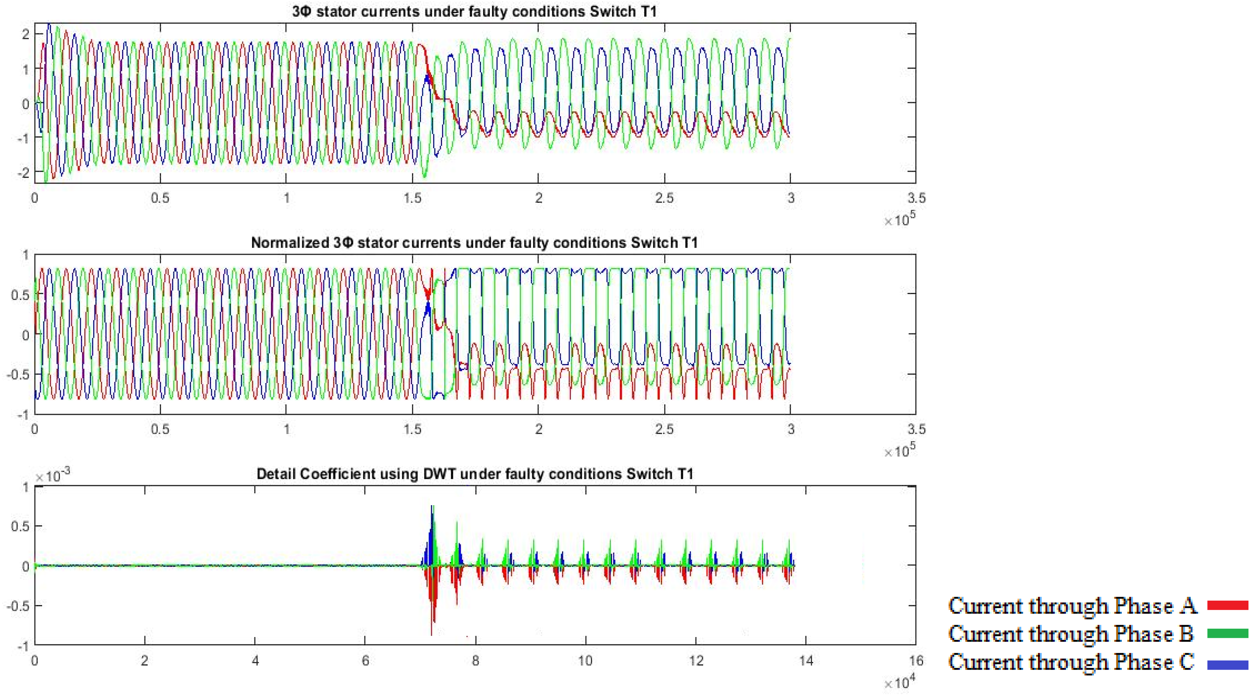
  • Park’s Vector Normalization: To eliminate the influence of load variations on current magnitudes, the 3ϕ stator currents are normalized using the modulus of the Park’s vector. This normalization makes diagnostic features consistent across varying load and frequency conditions.
  • Wavelet Transform for Feature Extraction: DWT captures both time and frequency domain characteristics of the normalized stator currents, allowing for the identification of transient patterns caused by OCFs.
  • ReliefF Algorithm for Feature Selection: This algorithm reduces computational complexity by selecting the most relevant features that distinguish between healthy and faulty conditions, thereby improving model generalization and avoiding overfitting.
  • Extreme Gradient Boosting (XGBoost): XGBoost is employed as the final fault classifier due to its speed, accuracy, and ability to handle imbalanced datasets. To optimize performance, a random search (RS) is used over a traditional grid search (GS) for hyperparameter tuning, offering faster convergence and better exploration of the parameter space.

1.3. Contribution of the Work

The key contributions of this research are as follows:
  • Development of a Threshold-Independent OCF Diagnosis Framework: The proposed method eliminates the dependency on threshold values by introducing Park’s vector normalization, ensuring reliable diagnosis performance under varying load and frequency conditions.
  • Efficient Feature Engineering for Accurate Fault Diagnosis: Leveraging DWT for extracting fault-revealing features from normalized stator currents and the ReliefF algorithm for selecting the most relevant features significantly enhances diagnosis accuracy while reducing computational burden.
  • Integration of XGBoost for Robust and Fast Fault Classification: A novel application of XGBoost is introduced for multi-class OCF diagnosis. The model excels in handling class imbalance, maintains high fault detection accuracy, and achieves rapid classification with detection times as low as 8 ms.
  • Hyperparameter Optimization Using Random Search: The use of an RS for XGBoost tuning improves model efficiency by reducing training time and avoiding unnecessary evaluations typical in a grid search.
  • Comprehensive Fault Coverage and Validation: The system successfully diagnoses 22 fault conditions, including single and multiple OCFs in different phases and legs, under dynamic load and frequency conditions, demonstrating the scalability and robustness of the proposed method.
  • Real-Time Applicability and Generalization: The proposed diagnostic framework shows strong potential for real-time deployment in industrial environments, with high adaptability to real-world disturbances such as load transients and frequency variations.
This work proposes a threshold-independent OCF diagnosis using Park’s vector normalization, DWT-based feature extraction, and ReliefF for efficient selection. With XGBoost optimized via a random search, it accurately detects 22 fault scenarios in real time under varying loads and frequencies, ensuring robust industrial applicability.
The 3ϕ V/F-controlled VSI under healthy and OCF conditions, and the proposed OCF diagnosis for 3ϕ V/F-controlled VSIs under variable load conditions at different frequencies, are explained in Section 2. The implementation of the proposed system is reported in Section 3 and results are presented to evaluate the fault diagnosis performance in Section 4.

2. The OCF Analysis for 3ϕ V/F-Controlled VSIs

The major faults of 3ϕ V/F-controlled VSIs are categorized below and shown in Figure 1.
  • AC line faults [F1];
  • DC bus faults [F2];
  • Power diode faults [F3–4];
  • DC link electrolytic capacitor faults [F5];
  • Switching device faults [F6–8];
  • Faults in control circuitry [F9].
IGBTs are used as switching devices in many 3ϕ V/F-controlled VSIs. IGBT faults are classified into three types:
  • Short-circuit fault (SCF);
  • Intermittent gate-misfiring fault (IGMF);
  • Open-circuit fault (OCF).
The timely diagnosis and protection against SCFs is required, as SCFs result in extremely severe stress on the switching devices. Unfortunately, an SCF is a frequently occurring fault, which arises because of voltage and current stress when the device is in forward blocking mode or carrying load current. In an SCF condition, the driver circuit of the healthy switch of the same leg should be blocked immediately to avoid shoot-through faults. Otherwise, the phase current will constantly rise. SCFs are not simple to deal with, as the time between fault occurrence and breakdown is negligible; normally, it is 10 μs. Hence, the majority of the existing IGBT SCF protection techniques are hardware-based circuits.
IGMFs occur because of missing one of the firing pulses. The recurrence of this fault results in an OCF. A further reason for an OCF is the failure of the isolated drive amplifier in the firing circuit. If the IGBT in an upper part of leg A is affected by an OCF, then the current conducting through phase A will pass through the bypass diode. The phase A voltage depends on switching pattern of the IGBT in a lower part of leg A and the polarity of phase A current. This leads to the addition of a DC current offset in both the faulty and healthy phases.
This DC current offset generates unbalanced current stress in the upper and lower switching devices of leg A. The DC component generates a pulsating torque. At the minimum operating frequency, the pulsating torque has a low frequency, which generates fluctuations in IM and leads to an increasing load on the VSI. A further increase in the load of the VSI may lead to a catastrophic breakdown with the failure of the drive system. This type of drive failure can cause a sever difficulty, which costs a lot of money and is quite dangerous from safety point of view. In 3ϕ V/F-controlled VSIs, the change in output voltage due to faults causes an imbalance in the three-phase currents. They are noticeable and an early detection method can avoid such serious faults with great effort. If an open-circuit fault remains undetected, it will result in secondary faults in the IM drive system. For this reason, the OCF diagnosis of switching devices has become an interesting field of research.

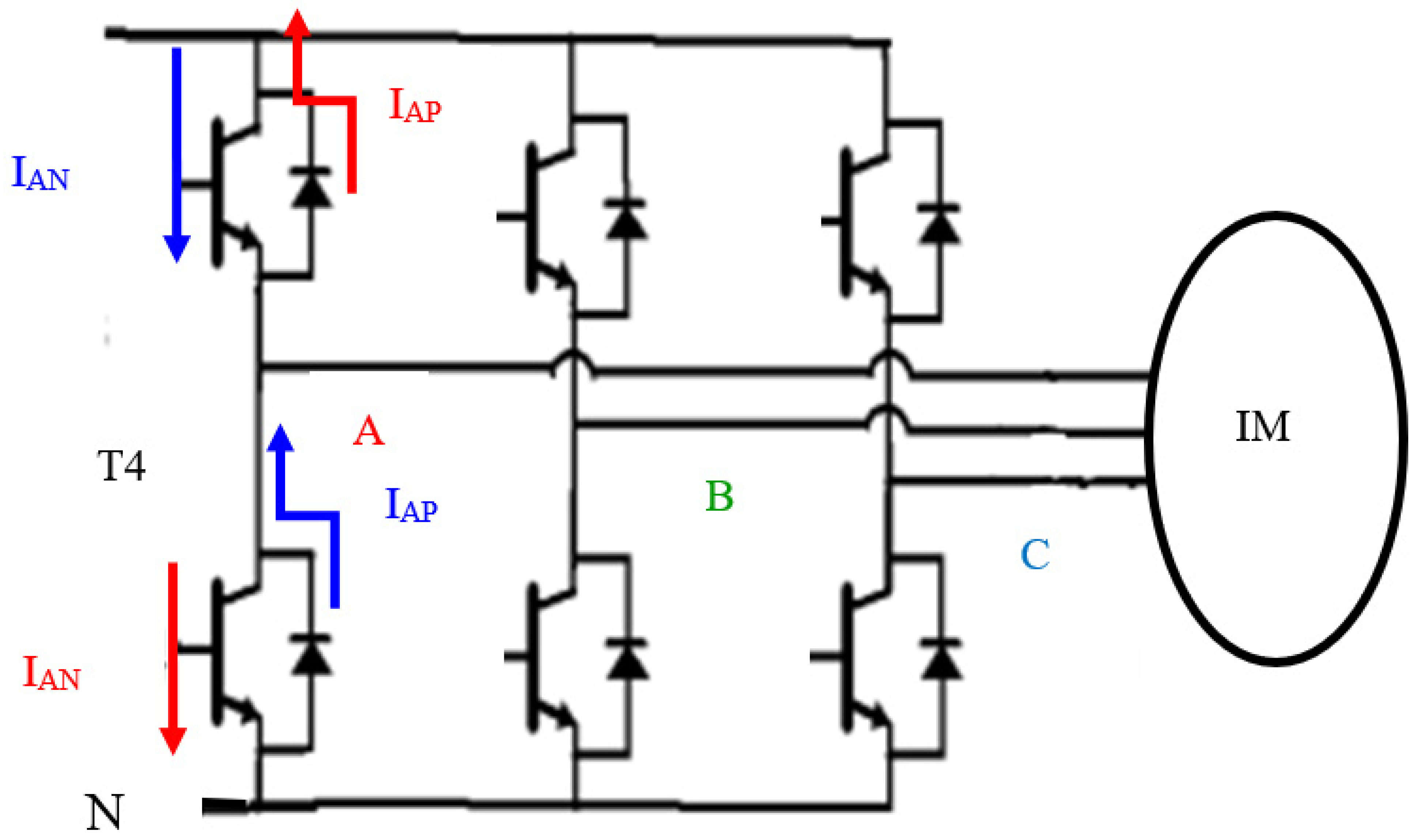
2.1. VSI Under Healthy and Open-Circuit Faulty Conditions

The circuit diagram of 3ϕ V/F-controlled VSIs is shown in Figure 2. The positive (IAP) and negative (IAN) currents are conducting through the A-phase. The switching sequence of IGBTs T1 to T6 in the 180° mode of operation under a healthy condition is given in Table 1. Every IGBT conducts for an angular frequency of 180°. Three IGBTs are in the ON state at any instant of time. When T1 is switched ON, terminal A is connected to positive terminal of the input DC voltage. When T4 is switched on, terminal A is carried to the negative terminal of the DC input voltage. In one cycle, there are six modes of operation, and each mode is of 60° duration.
The switching sequence for the IGBT T1 OCF condition is shown in Table 2. As shown in Figure 3, the phase current IA is negative in the IGBT-T1 OCF condition. In this condition, the A-phase only has a negative current, because the faulty switch T1 cannot conduct current during the positive half cycle. Also, current cannot conduct through freewheeling diode D1 because the voltage at the point A-pole is greater than the band C poles.

2.2. OCF Diagnosis for 3ϕ V/F-Controlled VSIs Under Variable Load at Different Frequencies

The proposed system for OCF diagnosis for 3ϕ V/F-controlled VSIs under variable load conditions at different frequencies is shown in Figure 4.
The 3 ϕ stator currents of a 3ϕ V/F-controlled VSI are represented in Equation (1).
i s = i a i b i c
where i a ,   i b ,   a n d   i c   are the instantaneous phase currents. These currents help as the main parameters for OCF diagnosis, as any deviation in the switching operation of the VSI marks the current waveforms. By investigating 3 ϕ stator currents, faults can be precisely identified and classified.
The Id and Iq are calculated using Equations (2) and (3).
I d = 2 3 i a 1 6 i b 1 6 i c
I q = 1 2 i b i c
The Park’s vector modulus and normalized three-phase current of the voltage source inverter are calculated using Equation (4) and Equation (5), respectively.
I s ¯ =   I d 2 + I q 2
I N o r m =   i s I ¯ s
Because of this normalization process, the normalized phase currents ( I N o r m ) will always take values within the range of ± 0.81, which is independent of the measured current’s amplitude. The features are extracted from the normalized current signals ( I N o r m ) to facilitate a correct OCF diagnosis. This is attained using DWT, which offers a time–frequency representation of the signal. Contrasting the Fourier Transform, which simply deals with frequency-domain information and drops time localization, DWT captures sudden rises or falls in the current signal as a result of fault occurrence by analyzing the signal in both the time and frequency domains. The approximate coefficients A k I N o r m and detail coefficients D k I N o r m are obtained using DWT decomposition of normalized phase currents ( I N o r m ) at the n level, as given by Equation (6) and Equation (7), respectively.
A k I N o r m = i = 1 m I i N o r m ϕ n , k i
D k I N o r m =   i = 1 m I i N o r m Ψ n , k ( i )
ϕ n , k i and Ψ n , k ( i ) are the scaling and wavelet functions, respectively, m represents the total number of samples, and k is a shifting parameter.
The subsequent important step is feature selection, which is used to categorize the most significant features for OCFs. The ReliefF algorithm (RA) is used for this reason, as it successfully ranks features based on their capability to differentiate OCFs. Feature selection is important, as it decreases computational complexity, avoids unnecessary processing time, avoids overfitting by removing inappropriate features that might mislead the model, as well as increases classification accuracy by retaining only the utmost important features. Mathematically, the RA allocates a weight to each feature, updating it based on its capability to separate different fault classes. Ranking extracted features are based on their assigned weights and selecting only the top-ranked features. The weight is updated using Equation (8).
W D k I N o r m =   W ( D k I N o r m ) n e a r e s t   h i t P D k I N o r m n e a r e s t   m i s s P D k I N o r m
The RA uses these nearest neighbors to update feature weights, confirming that features provided to class differences obtain greater meaning. The nearest hit denotes the nearby sample in the same class; however, the nearest miss is the neighboring sample from a dissimilar class. Features with higher values are measured more significantly for OCFs, as they improve the differentiation between faulty and healthy conditions. These selected features (FSel) are then used to train XGBoost, which performs fault diagnosis with improved accuracy and efficiency. XGBoost is selected for its effectiveness in handling imbalanced data; its capacity to offer faster training times with greater accuracy is due to its ensemble learning approach.
An XGBoost classifier is trained to classify healthy or faulty switches in a 3ϕ V/F-controlled VSI. The selected features are used as inputs to learn patterns associated with various fault conditions. XGBoost’s capability to identify complex relationships in the data enhances the reliability of OCF diagnosis, ensuring the effective detection of OCFs in the 3ϕ V/F-controlled VSI.
XGBoost is an ensemble learning technique intended to optimize speed and performance, excelling appropriately for complex classification tasks like OCF diagnosis in 3ϕ V/F-controlled VSIs. XGBoost’s architecture relies on a boosting framework that sequentially adds DTs, each of which corrects the mistakes made by its predecessor. This repetitive process continues until the particular number of trees is reached or the residuals are reduced. XGBoost helps prevent overfitting by using a custom objective function. This objective function combines a loss function with a regularization term. For effective feature separation, DTs use a greedy algorithm to select optimal split points based on information gain. In gradient boosting, the gradients of the previous trees are calculated to optimize predictions by fitting subsequent trees to the residual errors. The max_depth parameter in XGBoost controls the depth of individual DTs, preventing them from becoming too complex and overfitting to the training data. By limiting the depth, XGBoost effectively regulates model complexity while ensuring that trees generalize well to unseen data. Moreover, it expeditiously handles imbalanced data by allocating higher weights to minority classes, improving the ability to properly categorize faulty conditions even when healthy cases command the dataset. XGBoost parameter optimization for OCF diagnosis in 3ϕ V/F-controlled VSIs are given in Table 3.
The performance of OCF diagnosis in 3ϕ V/F-controlled VSIs under variable load conditions and different operating frequencies is enhanced using an RS for hyperparameter tuning in XGBoost. In contrast to a GS, an RS selects values arbitrarily from the hyperparameter space given in Table 3. This improves efficiency by reducing computation time while still searching for the best model settings. The steps to tune XGBoost using an RS are as follows.
  • Choose Random Hyperparameters: Set a fixed number of trials like 50 to 100. For every iteration, XGBoost is trained using an altered arbitrarily selected combination of hyperparameters from Table 3.
  • Check Model Performance: 5-fold cross-validation is used to test how well the model works on different data samples. The best model is selected based on performance measures like accuracy, F1-score, and Mean Squared Error (MSE).
  • Avoid Overfitting with Early Stopping: The model is unceasingly checked, and training stops if there is no development after 10 rounds. This confirms that the model does not remember noise and works on new data.
  • Select the Best Model: After testing various combinations, the one with the maximum accuracy and lowermost error is preferred.
Using RS, XGBoost is fine-tuned efficiently for OCF diagnos in 3ϕ V/F-controlled VSIs, making the system more accurate, reliable, and fast.

3. Implementation

The proposed method can diagnose the following 22 possible combinations of OCFs in a 3ϕ V/F-controlled VSI:
  • One healthy condition;
  • Six classes of single-switch open-circuit faults;
  • Three classes of double-switch open-circuit faults in same phase;
  • Twelve classes of double-switch open-circuit faults in different phases.
From above listed classes, case wise, some faulty conditions are considered for the analysis of proposed OCF. In total, nine conditions are considered. These conditions are mentioned below:
  • Single-switch open-circuit fault in upper part of leg (IGBT T1);
  • Single-switch open-circuit fault in lower part of leg (IGBT T4);
  • Single-phase open-circuit fault i.e., double switch fault in same leg (IGBTs T1T4);
  • Double-switch fault in different legs (IGBTs T1T6);
  • Double-switch fault in upper part of two legs (IGBTs T1T3);
  • Double-switch fault in lower part of two legs (IGBTs T4T6);
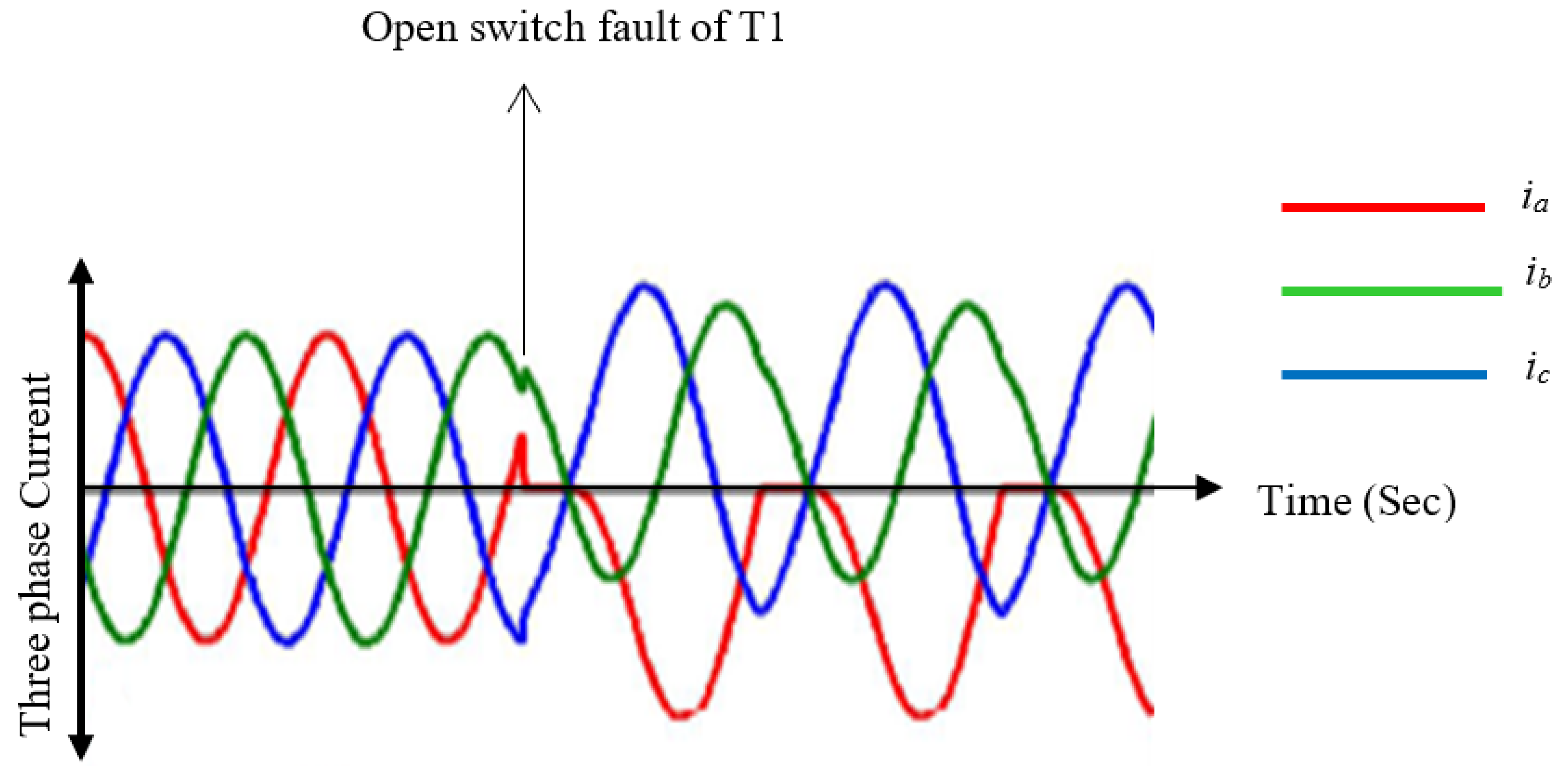
  • Sudden change in load or current waveform;
  • Load variation during faulty condition;
  • Fault diagnosis at different frequencies.
The specifications of the hardware used to implement the proposed method are given in Table 4. The 3 ϕ stator currents of 3ϕ V/F-controlled VSIs are collected and converted into a packet for further analysis. Each packet consists of 10,000 samples, which represent one complete cycle of 3 ϕ stator currents. The load variations were tested by varying the load power within the range of 500 W to 1.5 kW. The load impedance configuration consisted of a resistor of 0.20 Ω and an inductor of 10 mH, representing a typical RL load. The system operated with an output voltage with a 230 V peak and an output current of 3.063 A. Additionally, the tests were conducted across a range of output frequencies from 40 Hz to 70 Hz to evaluate the system’s performance under different operating conditions. The 3 ϕ stator currents are converted into the d-q plane using PVT. PVT allows for fault diagnosis in a stationary reference frame by converting 3ϕ currents into 2ϕ direct-quadrature (d-q) components. PVT creates a symmetric circular pattern, as shown in Figure 5, in the d-q plane under healthy conditions of switching devices. While in the presence of OCFs, the pattern becomes asymmetrical. These shapes, with the help of the pattern recognition method, can diagnose only a single-switch OCF. The 3 ϕ stator currents are normalized using Park’s vector modulus, which converts magnitude in the range of ± 0.81. The 3 ϕ stator currents and 3 ϕ-normalized stator currents using Park’s vector modulus is shown in Figure 6.
The choice of a mother wavelet is dependent on the potential for a particular application; therefore, DWT does not have a fixed mother wavelet such as other transforms like Fast Fourier Transform or Discrete Cosine Transform. The different mother wavelets give different results for the analysis of the same signal; hence, the selection of the mother wavelet and signal decomposition level is a crucial task in fault diagnosis. The commonly used mother wavelets are Daubechies (DB), Symmlet, Coiflet, and Battle-Lamarie, each performing differently. The selection of the mother wavelet is determined by parameters like symmetry, orthogonality, compact support, and vanishing moments; sometimes, multiple wavelets have similar properties, and if so, the nearest to the original signal is preferred. Another problem is choosing the correct decomposition level, which is typically determined through testing as well as understanding the pattern of data, and with the maximum level being contingent on the sample count, as the data are halved at each level. In this work, the selection of a mother wavelet is carried out based on the analysis of signals using different mother wavelets at different levels of decomposition. The DB2 wavelet was chosen for its effectiveness in analyzing non-stationary, transient signals like three-phase stator currents during fault conditions. It balances compact support, orthogonality, and vanishing moments, which are essential for detecting subtle deviations in open-circuit faults. At level 2, DB2 provided the best feature extraction for healthy vs. faulty conditions. The analysis of a non-stationary 3 ϕ-normalized stator current signal using the DB2 mother wavelet at level 2 under healthy and faulty conditions of device T1 is shown in Figure 7, which reveals that wavelet transform coefficients ( D k I N o r m ) clearly differentiate between the healthy and faulty conditions.
The RA gives weights to features, which are derived from their capability to separate healthy and faulty switches. It examines every feature by matching its values among various group labels, for example, healthy and faulty. The algorithm computes the significance of each feature by finding its nearest neighbors within the similar class, identified as the nearest hit, and different classes, known as the nearest miss. Features that regularly differentiate between situations collect higher weight scores, whereas those with a negligible impact are given lower scores. An example of feature weights assigned by ReliefF is given in Table 5.
Features with scores above the cutoff, for example, 0.75, are considered important and taken for OCF diagnosis, whereas those scoring below the cutoff are rejected to decrease computational complexity. Depending on the predefined threshold value, the mean of energy of detail coefficients, wavelet coefficients, RMS value, standard deviation, and kurtosis features are selected. Table 5 presents the final set of features chosen for classification.
An RS was preferred for hyperparameter tuning in XGBoost due to its efficiency in exploring the hyperparameter space, reducing computation time compared to a grid search. The selected features are used to train the XGBoost model, utilizing an RS for hyperparameter optimization. The dataset comprises five features, identified by high weight scores using the RA, and standardization confirms all features remain in the same range to increase model convergence speed. The dataset is divided into three subsets: a Training Set (70%) for learning model parameters, a Validation Set (15%) for hyperparameter tuning and early stopping, and a Test Set (15%) for performance evaluation on unseen data. To optimize XGBoost, the RS capably chooses hyperparameters, comprising the number of estimators, learning rate, and maximum depth. The tested values consist of the number of estimators [50, 100, 150, 200, 250], learning rate [0.001, 0.005, 0.01, 0.05, 0.1], and maximum depth [3, 5, 7, 9]. This technique expedites tuning by minimizing unwanted evaluations while still finding an optimal model configuration. The output layer involves six classes (B0 to B5), signifying six switching device conditions (T1 to T6) in the system. This architecture permits XGBoost to capably learn complex fault patterns while confirming accurate classification performance. The training progress, including accuracy and loss reduction over epochs, is shown in Figure 8.

4. Results and Discussion

The proposed OCF diagnosis method for 3ϕ V/F-controlled VSIs under variable load conditions at different frequencies demonstrates remarkable accuracy and efficiency, with fault detection times consistently ranging between 10 ms and 20 ms under various fault conditions. The results showcase the robustness and reliability of the approach, particularly in its ability to handle multiple fault scenarios with minimal detection delays. Detailed discussions for each condition are presented below.

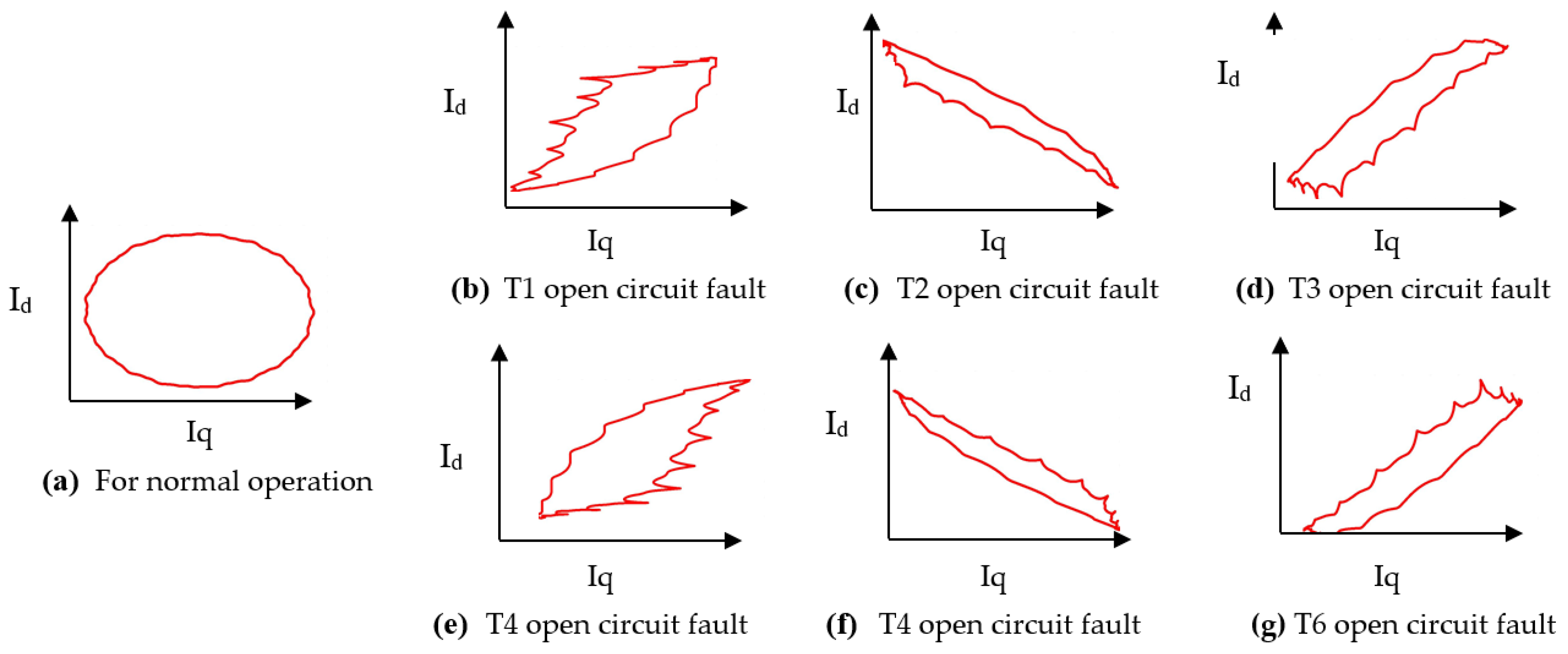
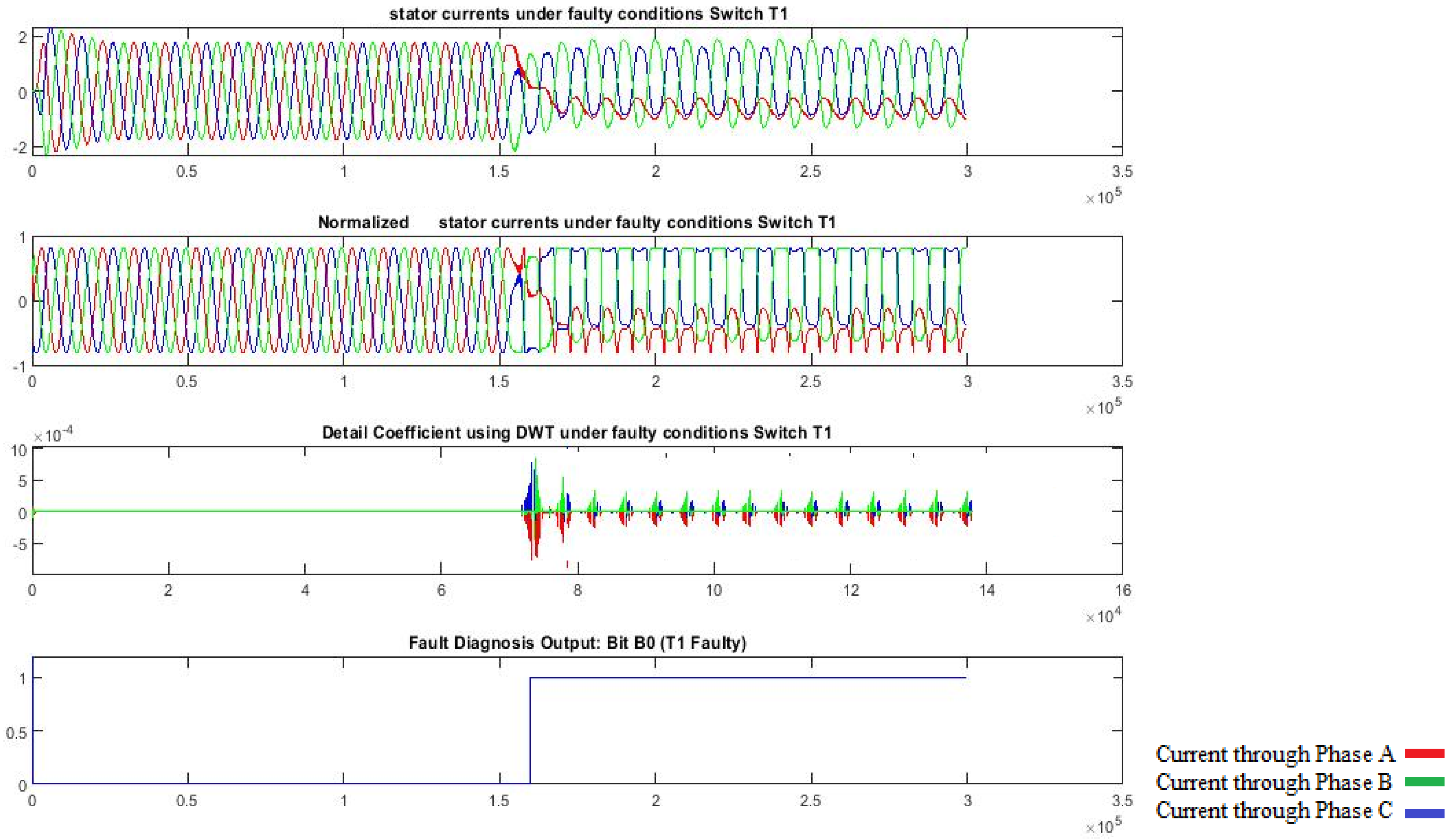
4.1. T1 Open-Circuit Fault

Figure 9 illustrates the time-domain waveforms corresponding to a T1-OCF. In this scenario, a noticeable disturbance is observed in the phase current corresponding to T1, while the other two-phase currents show compensatory behavior. The normalized current waveforms highlight the asymmetry caused by the OCF. The XGBoost model-processed output accurately identifies this abnormality, triggering the fault diagnosis mechanism swiftly. The method’s sensitivity to subtle changes in the waveform is particularly noteworthy, ensuring prompt fault identification.

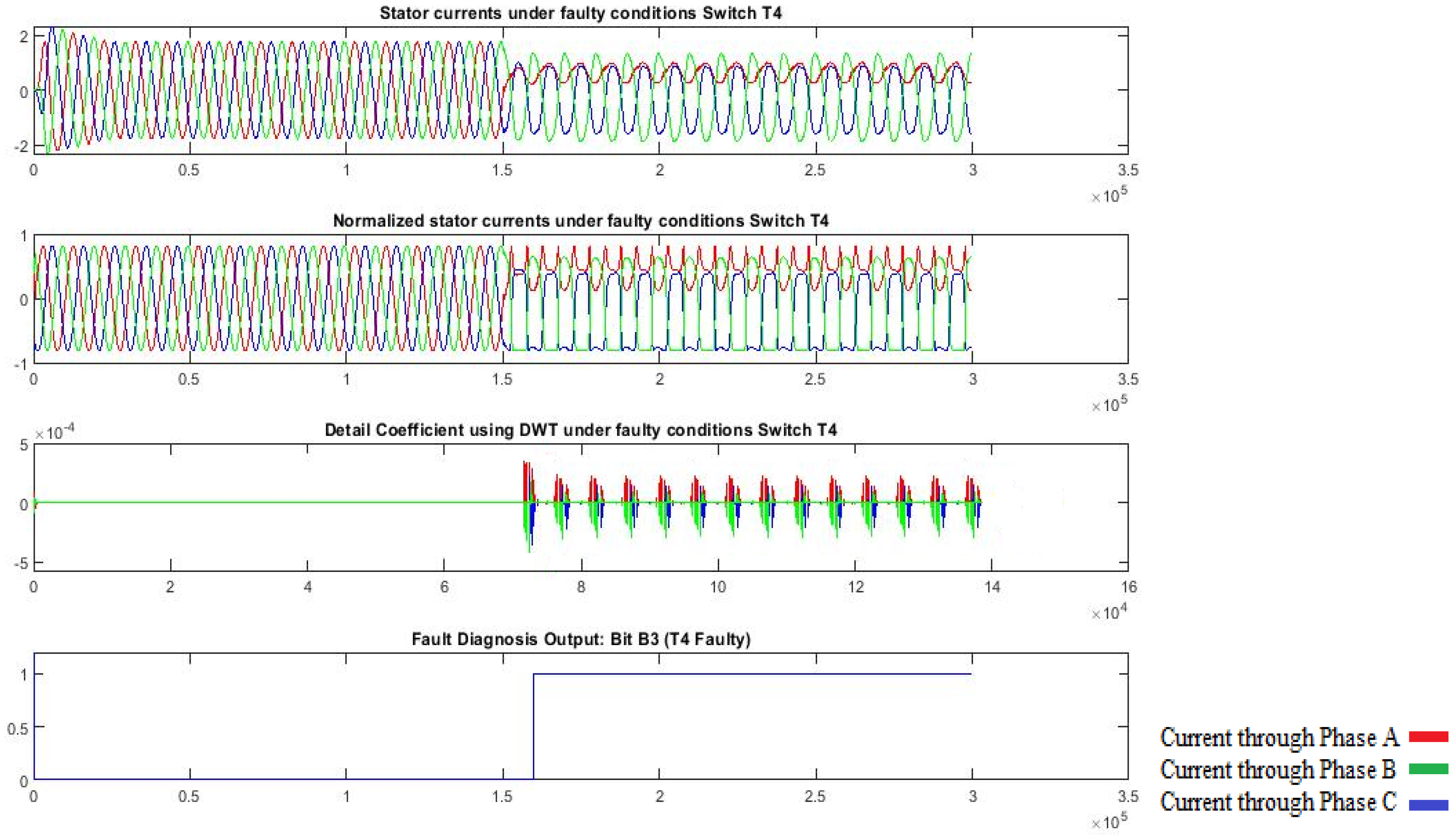
4.2. T4 Open-Circuit Fault

Concerning the results for a T4 open-circuit fault, here, the fault introduces a distinct change in the time-domain waveform of the affected phase; this leads to an imbalance that propagates across the three-phase system, as is shown in Figure 10. The normalized currents reflect this imbalance, and the XGBoost model-processed output effectively recognizes the unique pattern associated with the T4 fault. Despite the different fault location compared to the T1 scenario, the detection time remains within 20 ms, highlighting the method’s consistency and adaptability.

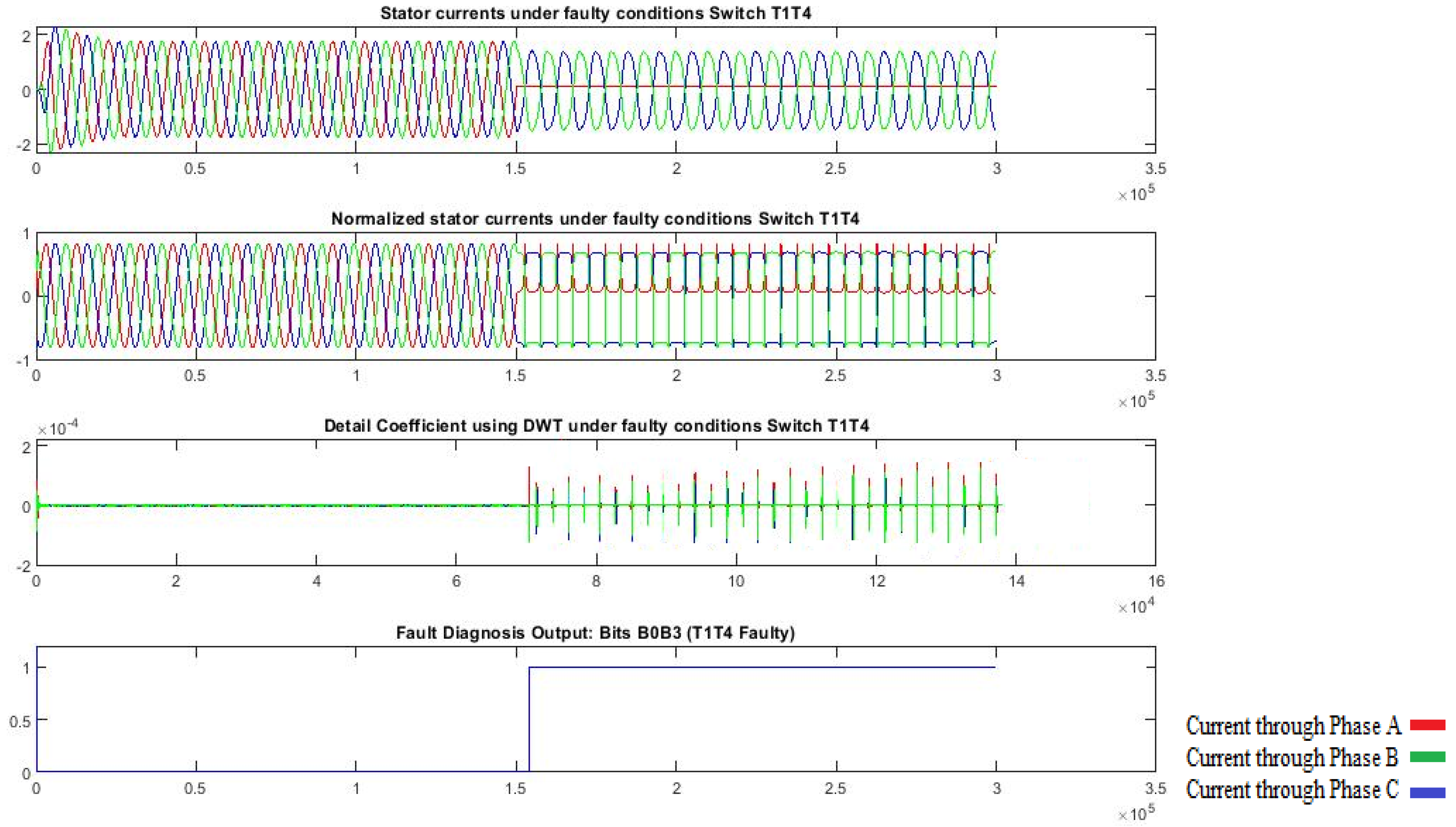
4.3. T1-T4 Open-Circuit Fault

Figure 11 illustrates the scenario of a T1-T4 open-circuit fault, representing a more complex situation involving an open-phase fault. The XGBoost model-processed output efficiently distinguishes this complex pattern from other fault types, correctly diagnosing the dual open-circuit condition. Despite the increased complexity, the detection time is maintained around 10 ms, reflecting the robustness of the proposed method. This demonstrates the system’s ability to effectively manage multiple simultaneous faults without compromising the detection speed or accuracy.

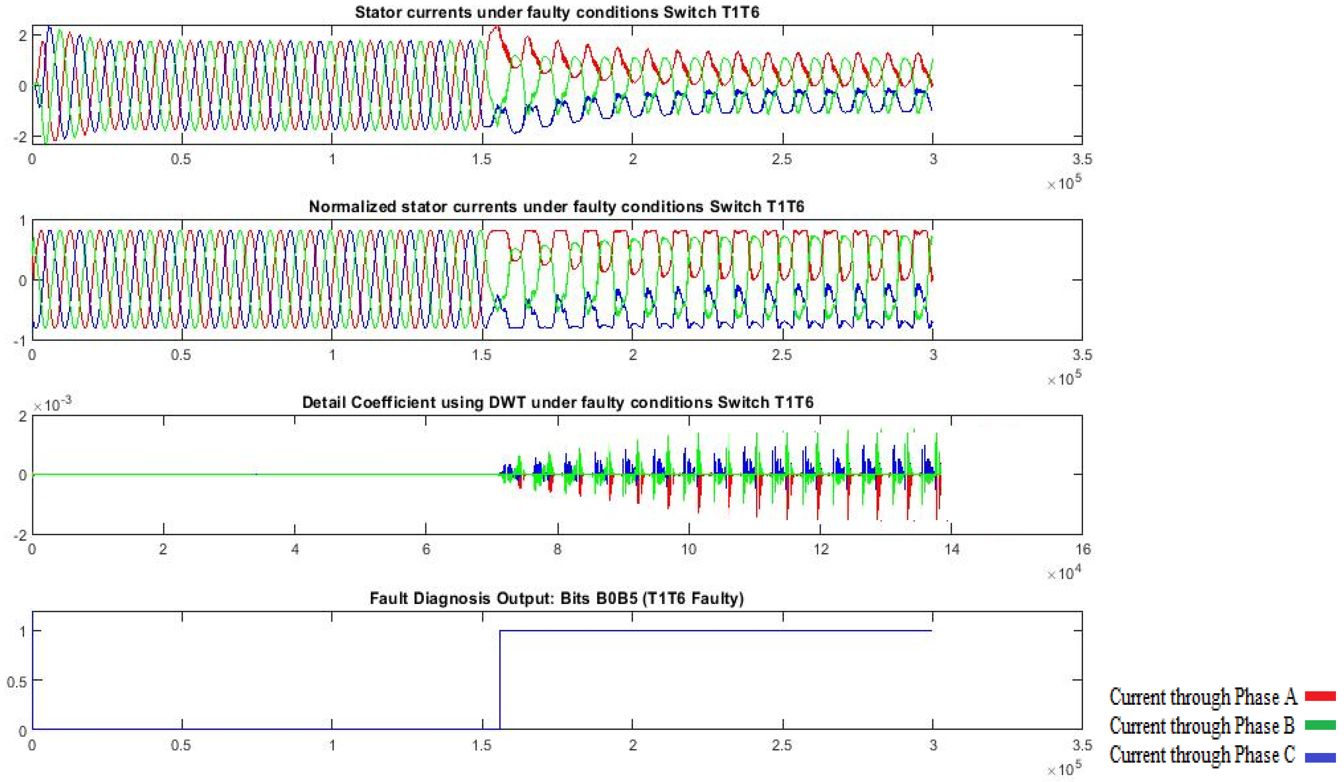
4.4. T1-T6 and T1-T3 Open-Circuit Faults

Figure 12 and Figure 13 display the results for T1-T6 and T1-T3 open-circuit faults, which represent even more severe fault conditions. This scenario causes a substantial disruption across all three phases, leading to highly irregular current waveforms. The normalized currents display significant deviations from the expected patterns, which are efficiently captured by the XGBoost model-processed output. The diagnosis mechanism accurately identifies the fault, despite the extensive impact on the system. Interestingly, the detection time remains within 20 ms, demonstrating the method’s exceptional capability to handle severe multi-phase faults with minimal latency. The consistency between the results in Figure 12 and Figure 13 reinforces the reliability of the approach under repetitive testing conditions.

4.5. T4-T6 Open-Circuit Fault

Figure 14 shows the results for a T4-T6 open-circuit fault, another complex dual-fault scenario. This condition induces distinctive distortions in the waveforms corresponding to the affected phases, with resultant imbalances in the remaining phase. The normalized currents clearly illustrate these anomalies. The XGBoost model-processed output accurately correlates this unique pattern to the T4-T6 fault condition, ensuring a precise diagnosis. The detection time in this case is around 20 ms, which is well within the expected range, showcasing the method’s efficiency even for challenging fault combinations. The ability to differentiate this dual-fault scenario from others further highlights the effectiveness of the proposed approach.

4.6. T1 Open-Circuit Fault with Sudden Load Changes

Figure 15 presents the case of a T1 open-circuit fault combined with sudden load changes. This scenario introduces dynamic disturbances in the time-domain waveforms due to the abrupt load variations, which could complicate fault diagnosis. However, the proposed method effectively segregates the fault signature from the transient effects of the load change. The XGBoost model-processed output remains unaffected by the dynamic fluctuations, accurately diagnosing the T1 fault. This result is particularly significant, as it validates the method’s reliability under real-world operating conditions where load changes are common.

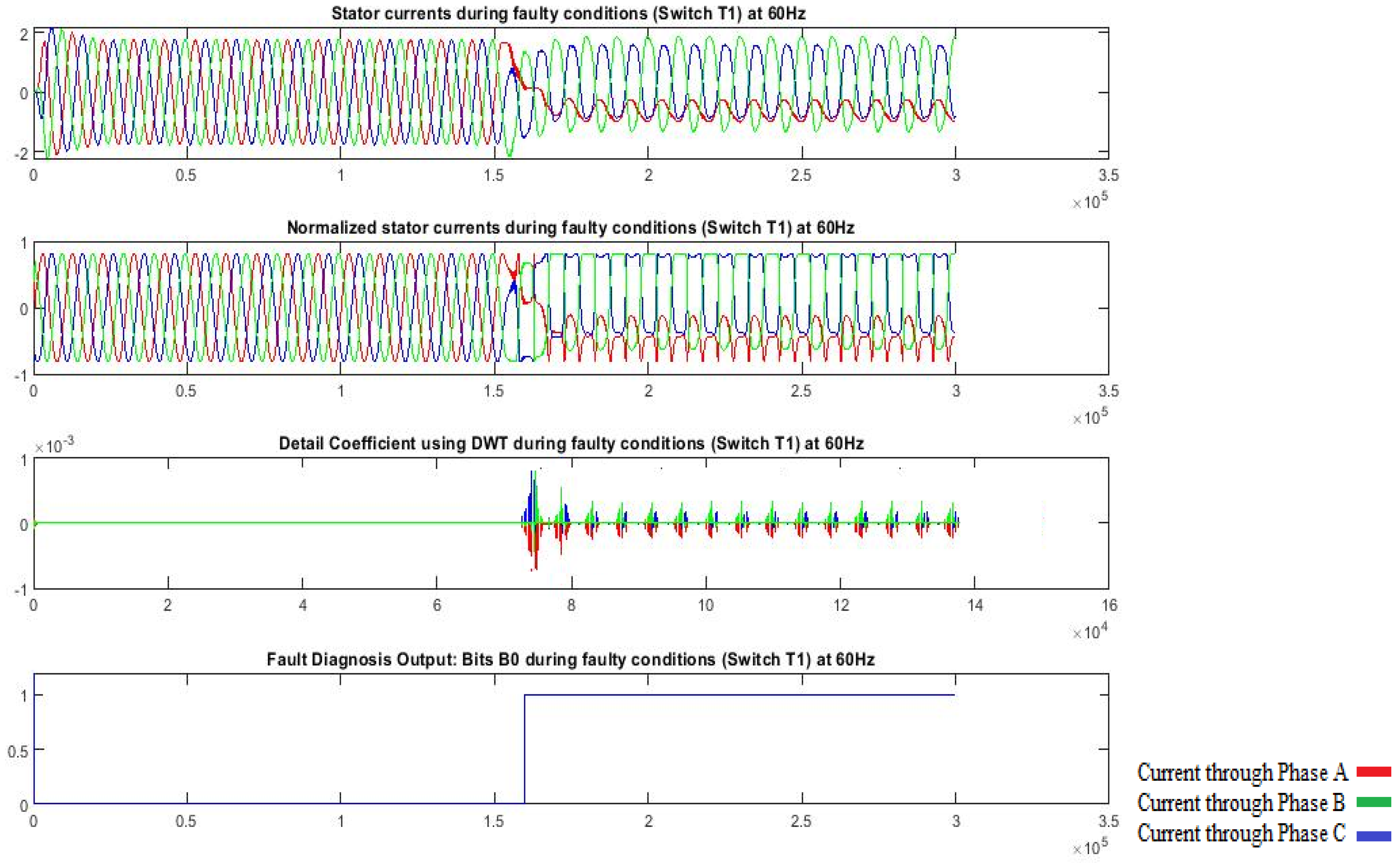
4.7. T1 Open-Circuit Fault at 60 Hz Frequency

Figure 16 shows the results for a T1 open-circuit fault at a 60 Hz frequency. The change in operating frequency affects the fundamental component of the current waveforms, which could potentially impact the fault diagnosis mechanism. Nevertheless, the proposed method successfully adapts to this frequency change, maintaining an accurate fault diagnosis. The normalized currents display the characteristic pattern of a T1 fault, and the XGBoost model-processed output precisely identifies this condition without any misclassification. The detection time is around 20 ms. This demonstrates the versatility of the method in handling frequency variations while preserving its diagnostic accuracy.
The statistical performance comparison of various OCFDM classification methods is presented in Table 6. The Wavelet-Fuzzy Method [22] achieved an accuracy of 92%, while the Wavelet-Neural Network [23] improved it to 95%. A hybrid approach combining Park’s vector and Wavelet-NN [24] further enhanced the accuracy to 96%. The hardware-based system [25] reached 98% accuracy with a low false positive rate of 2%. Notably, the proposed method integrating Park’s vector normalization with XGBoost outperformed all previous methods, achieving the highest accuracy of 99%, precision of 97%, recall of 96%, and the lowest false positive rate of just 1%, demonstrating its effectiveness and reliability.

5. Conclusions

The open-circuit fault diagnosis for 3ϕ V/F-controlled voltage source inverters under variable load conditions at different frequencies is a challenging task. Few methods have been implemented to diagnose open-circuit faults, but they have limitations such as the need for threshold adjustment according to load variations, difficulties in collecting data under variable load conditions to train fault classification algorithms, and challenges in avoiding false alarms at variable frequencies. The proposed method in this paper effectively diagnoses open-circuit faults in 3ϕ V/F-controlled voltage source inverters using the normalized current method. Normalized currents help to keep the features the same under all load conditions while clearly showing the difference between faulty and healthy conditions. The proposed method uses Park’s vector transform, wavelet transform, ReliefF algorithm, and an XGBoost model. In this study, XGBoost was utilized for optimal hyperparameter tuning in the OCF diagnosis of 3ϕ V/F-controlled VSIs. A random search was preferred over a grid search due to its ability to accelerate the tuning process, explore a wider range of hyperparameter combinations, and efficiently balance accuracy with computational cost. The proposed approach enhances model convergence while maintaining robustness, making it a practical and effective solution for real-time fault classification in power electronic systems. The results clearly demonstrate that the proposed method consistently achieves rapid and accurate fault diagnosis across all tested scenarios, with detection times ranging from 8 ms to 18 ms. The proposed approach proves to be highly effective in recognizing complex fault patterns, even under challenging conditions such as simultaneous faults, sudden load changes, and frequency variations. The method’s robustness, adaptability, and reliable performance make it a highly suitable solution for real-time fault diagnosis in three-phase systems.

Author Contributions

Methodology, P.T.-W.; Software, N.G.; Investigation, R.B.D.; Data curation, A.N.; Writing—original draft, R.B.D.; Writing—review & editing, R.B.D. All authors have read and agreed to the published version of the manuscript.

Funding

This research received no external funding.

Data Availability Statement

The original contributions presented in this study are included in the article. Further inquiries can be directed to the corresponding author.

Conflicts of Interest

The authors declare no conflict of interest.

References

  1. Luo, Y.; Zhang, L.; Chen, C.; Li, K.; Yu, T.; Li, K. FRA-Based Parameter Estimation for Fault Diagnosis of Three-Phase Voltage-Source Inverters. IEEE Access 2023, 11, 113836–113847. [Google Scholar] [CrossRef]
  2. Park, Y.J.; Fan, S.K.S.; Hsu, C.Y. A review on fault detection and process diagnostics in industrial processes. Processes 2020, 8, 1123. [Google Scholar] [CrossRef]
  3. Ajra, Y.; Hoblos, G.; Al Sheikh, H.; Moubayed, N. A Literature Review of Fault Detection and Diagnostic Methods in Three-Phase Voltage-Source Inverters. Machines 2024, 12, 631. [Google Scholar] [CrossRef]
  4. Orosz, T.; Rassõlkin, A.; Arsénio, P.; Poór, P.; Valme, D.; Sleisz, Á. Current Challenges in Operation, Performance, and Maintenance of Photovoltaic Panels. Energies 2024, 17, 1306. [Google Scholar] [CrossRef]
  5. Mahafzah, K.A.; Obeidat, M.A.; Mansour, A.M.; Al-Shetwi, A.Q.; Ustun, T.S. Artificial-Intelligence-Based Open-Circuit Fault Diagnosis in VSI-Fed PMSMs and a Novel Fault Recovery Method. Sustainability 2022, 14, 16504. [Google Scholar] [CrossRef]
  6. Kwon, B.H.; Kim, S.H.; Kim, S.M.; Lee, K.B. Fault diagnosis of open-switch failure in a grid-connected three-level Si/Sic hybrid ANPC inverter. Electronics 2020, 9, 399. [Google Scholar] [CrossRef]
  7. Gnaciński, P.; Pepliński, M.; Muc, A.; Hallmann, D. Induction Motors Under Voltage Unbalance Combined with Voltage Subharmonics. Energies 2024, 17, 6324. [Google Scholar] [CrossRef]
  8. Gmati, B.; Ben Rhouma, A.; Meddeb, H.; Khojet El Khil, S. Diagnosis of Multiple Open-Circuit Faults in Three-Phase Induction Machine Drive Systems Based on Bidirectional Long Short-Term Memory Algorithm. World Electr. Veh. J. 2024, 15, 53. [Google Scholar] [CrossRef]
  9. Sonawane, V.R.; Patil, S.B.; Rajankar, O.S.; Idhate, S. Optimizing fault diagnosis in variable load conditions: A machine and deep learning approach for voltage source inverters. J. Integr. Sci. Technol. 2025, 13, 1057. [Google Scholar] [CrossRef]
  10. Sun, X.; Diao, N.; Song, C.; Qiu, Y.; Zhao, X. An Open-Circuit Fault Diagnosis Method Based on Adjacent Trend Line Relationship of Current Vector Trajectory for Motor Drive Inverter. Machines 2023, 11, 928. [Google Scholar] [CrossRef]
  11. Mendes, A.M.S.; Marques Cardoso, A.J. Voltage source inverter fault diagnosis in variable speed AC drives, by the average current Park’s vector approach. In Proceedings of the IEEE International Electric Machines and Drives Conference, Seattle, WA, USA, 9–12 May 1999; IEEE: New York, NY, USA, 2002; pp. 704–706. [Google Scholar]
  12. Rothenhagen, K.; Fuchs, F.W. Performance of Diagnosis Methods for IGBT Open Circuit Faults in Voltage Source Active Rectifiers. In Proceedings of the 2004 IEEE 35th Annual Power Electronics Specialists Conference, Aachen, Germany, 20–25 June 2004; IEEE: New York, NY, USA, 2004; Volume 6, pp. 4348–4354. [Google Scholar] [CrossRef]
  13. Peuget, R.; Courtine, S.; Rognon, J.P. Fault detection and isolation on a pwm inverter by knowledge-based model. IEEE Trans. Ind. Appl. 2002, 34, 1318–1326. [Google Scholar] [CrossRef]
  14. Park, J.; Kim, D.; Kim, S.; Lee, D.; Chun, M. G-ANFIS based fault diagnosis for Voltage-fed PWM Motor Drive Systems. In Proceedings of the IEEE Annual Meeting of the Fuzzy Information, 2004. Processing NAFIPS ’04, Banff, AB, Canada, 27–30 June 2004; IEEE: New York, NY, USA, 2004; pp. 379–383. [Google Scholar]
  15. Masrur, M.A.; Chen, Z.; Zhang, B.; Murphey, Y.L. Model-Based Fault Diagnosis in Electric Drive Inverters Using Artificial Neural Network. In Proceedings of the 2007 IEEE Power Engineering Society General Meeting, Tampa, FL, USA, 24–28 June 2007; IEEE: New York, NY, USA, 2007; pp. 1–7. [Google Scholar]
  16. Yan, Y.; Wu, J.; Cao, Y.; Liu, B.; Li, C.; Shi, T. An Open-Circuit Fault Diagnosis Method for Three-Level Neutral Point Clamped Inverters Based on Multi-Scale Shuffled Convolutional Neural Network. Sensors 2024, 24, 1745. [Google Scholar] [CrossRef] [PubMed]
  17. Zidani, F.; Diallo, D.; Benbouzid, M.H.H.; Naït-Saïd, R. Fuzzy detection and diagnosis of fault modes in a voltage-fed PWM inverter induction motor drive. In Proceedings of the IEEE International Conference on Electric Machines and Drives, San Antonio, TX, USA, 15 May 2005; IEEE: New York, NY, USA, 2005; pp. 748–753. [Google Scholar] [CrossRef]
  18. Mohammadhassani, A.; Mehrizi-Sani, A. Open-circuit submodule fault diagnosis in MMCs using support vector machines. IET Gener. Transm. Distrib. 2022, 16, 5015–5025. [Google Scholar] [CrossRef]
  19. Dhumale, N.R.; Dhumale, R.B.; Shelke, M.V.; Nikam, S.S.; Mane, P.B.; Sarawade, A.N. Fuzzy Logic Diagnostics for Open-Circuit Faults in Renewable Energy Voltage Source Inverters with Changeable Load Con-ditions. Int. J. Intell. Syst. Appl. Eng. 2024, 12, 80–86. [Google Scholar]
  20. Khan, F.A.; Shees, M.M.; Alsharekh, M.F.; Alyahya, S.; Saleem, F.; Baghel, V.; Sarwar, A.; Islam, M.; Khan, S. Open-Circuit Fault Detection in a Multilevel Inverter Using Sub-Band Wavelet Energy. Electronics 2021, 11, 123. [Google Scholar] [CrossRef]
  21. Singh, V.; Yadav, A.; Gupta, S. Combined Wavelet and Ann-Based Open-Switch Fault Detection and Classification in PV-Fed Multilevel Inverter. J. Inst. Eng. Ser. B 2024, 105, 217–228. [Google Scholar] [CrossRef]
  22. Dhumale, R.B.; Lokhande, S.D. Comparative Study of Fault Diagnostic Methods in Voltage Source Inverter Fed Three Phase Induction Motor Drive. IOP Conf. Ser. Mater. Sci. Eng. 2017, 197, 012006. [Google Scholar] [CrossRef]
  23. Charfi, F.; Sellami, F.; Al-Haddad, K. Fault Diagnostic in Power System Using Wavelet Transforms and Neural Networks. In Proceedings of the 2006 IEEE International Symposium on Industrial Electronics, Montreal, QC, Canada, 9–13 July 2006; IEEE: New York, NY, USA, 2007; Volume 2, pp. 1143–1148. [Google Scholar] [CrossRef]
  24. Dhumale, R.B.; Lokhande, S.D. Neural Network Fault Diagnosis of Voltage Source Inverter under variable load conditions at different frequencies. Meas. J. Int. Meas. Confed. 2016, 91, 565–575. [Google Scholar] [CrossRef]
  25. Dale, M.; Kamble, V.H.; Dhumale, R.B.; Nanthaamornphong, A. Open Switch Fault Diagnosis in Three-Phase Voltage Source Inverters Using Single Neuron Implementation. Processes 2025, 13, 1070. [Google Scholar] [CrossRef]
Figure 1. Faults in 3ϕ V/F-controlled VSIs.
Processes 13 01313 g001
Figure 2. Direction of currents conducting in three-phase VSI.
Processes 13 01313 g002
Figure 3. Simulation results concerning waveform during T1 open-circuit fault.
Processes 13 01313 g003
Figure 4. Proposed OCF diagnosis for 3ϕ V/F-controlled VSIs.
Processes 13 01313 g004
Figure 5. d-q patterns for healthy and faulty conditions.
Processes 13 01313 g005
Figure 6. The 3 ϕ stator currents and 3 ϕ-normalized stator currents using Park’s vector modulus.
Processes 13 01313 g006
Figure 7. Analysis of a non-stationary 3 ϕ-normalized stator current signal using the DB2 mother wavelet at level 2 under healthy and OCF conditions of device T1.
Processes 13 01313 g007
Figure 8. The training progress, including accuracy and loss reduction over epochs.
Processes 13 01313 g008
Figure 9. Results regarding the time-domain waveforms of the three-phase currents, the normalized currents, XGBoost model-processed output, and the diagnosis result of T1 open-circuit fault.
Processes 13 01313 g009
Figure 10. Results regarding the time-domain waveforms of the three-phase currents, the normalized currents, XGBoost model-processed output, and the diagnosis result of T4 open-circuit fault.
Processes 13 01313 g010
Figure 11. Results regarding the time-domain waveforms of the three-phase currents, the normalized currents, XGBoost model-processed output, and the diagnosis result of T1-T4 open.
Processes 13 01313 g011
Figure 12. Results regarding the time-domain waveforms of the three-phase currents, the normalized currents, XGBoost model-processed output, and the diagnosis result of T1-T6 open.
Processes 13 01313 g012
Figure 13. Results regarding the time-domain waveforms of the three-phase currents, the normalized currents, XGBoost model-processed output, and the diagnosis result of T1-T3 open.
Processes 13 01313 g013
Figure 14. Results regarding the time-domain waveforms of the three-phase currents, the normalized currents, XGBoost model-processed output, and the diagnosis result of T4-T6 open.
Processes 13 01313 g014
Figure 15. Results regarding the time-domain waveforms of the three-phase currents, the normalized currents, XGBoost model-processed output, and the diagnosis result of T1 open-circuit fault and sudden change in load conditions.
Processes 13 01313 g015
Figure 16. Results regarding the time-domain waveforms of the three-phase currents, the normalized currents, XGBoost model-processed output and the diagnosis result of T1 open-circuit fault at 60 Hz frequency.
Processes 13 01313 g016
Table 1. Switching sequence for healthy operation.
StateT1T2T3T4T5T6
1100011
2110001
3111000
4011100
5001110
6000111
Table 2. Switching sequence for IGBT T1 open-circuit fault.
StateT1T2T3T4T5T6
1000011
2010001
3011000
4011100
5001110
6000111
Table 3. XGBoost parameter optimization for OCF diagnosis in 3φ V/F-controlled VSIs.
ParameterDescriptionRecommended RangeTuning Strategy and Key Decisions
Learning RateControls step size for updating weights; affects convergence speed and generalization.0.01–0.1Random search explored fine-grained values (e.g., 0.01, 0.03, 0.05, 0.07, 0.1); selected based on validation accuracy and early stopping performance.
Number of TreesDetermines the number of boosting rounds; early stopping prevents overfitting.Start with 100, increase graduallyRandom search sampled values from 100 to 500 in steps of 50; early stopping with 10 rounds used to halt training on plateau.
Maximum DepthControls tree complexity; prevents overfitting while capturing fault patterns.3–6Random values in range [3, 6]; deeper trees avoided to reduce overfitting and improve generalization.
SubsamplingReduces overfitting by using a fraction of training data per boosting round.0.6–0.9Randomly sampled values from uniform distribution; values around 0.8 found optimal for balance.
Column SubsamplingEnhances model diversity by selecting a subset of features per tree.0.7–0.9Random search tried values in steps of 0.05; 0.8 selected based on consistent gain across folds.
L1 RegularizationControls model sparsity and complexity, preventing overfitting.0–0.1Tuned via random search; values close to 0.05 yielded sparse and interpretable models.
L2 RegularizationEnhances model robustness by penalizing large coefficients.0.1–1Random values between 0.1 and 1.0; moderate regularization (e.g., 0.3–0.5) found effective.
Scale Positive WeightAdjusts class imbalance by weighting faulty samples appropriately.Ratio of healthy to faulty samplesComputed dynamically based on training data distribution; included in random search to assess sensitivity.
Table 4. Specifications of VSI.
ParametersValues
DC Link Electrolytic Capacitor5000 µF
Load Inductance10 mH
Load Resistor0.20 Ω
Output AC Voltage230 Vp
Output Current3.0630 Amp
Output Frequency40–70 Hz
Load Power (Variable)500 W–1.5 kW
Table 5. Feature weights assigned by ReliefF.
Feature NumberFeature NameWeight Score RelevanceFeature Selected or Rejected
1Mean of Wavelet Coefficients0.88Selected
2Standard Deviation0.81Selected
3Kurtosis0.77Selected
4Skewness0.70Rejected
5Energy of Detail Coefficients0.91Selected
6Entropy0.65Rejected
7RMS Value0.84Selected
Table 6. Statistical performance comparison of OCFDMs.
MethodAccuracy (%)Precision (%)Recall (%)False Positive Rate (%)
Wavelet-Fuzzy Method [22]9290897
Wavelet-Neural Network [23]9593915
Hybrid Approach (Park’s Vector + Wavelet-NN) [24]9694924
Hardware based System [25]9896952
Proposed Method (Park’s Vector + XGBoost)9997961
Disclaimer/Publisher’s Note: The statements, opinions and data contained in all publications are solely those of the individual author(s) and contributor(s) and not of MDPI and/or the editor(s). MDPI and/or the editor(s) disclaim responsibility for any injury to people or property resulting from any ideas, methods, instructions or products referred to in the content.

