Article

Small-Signal Stability Analysis of Grid-Connected System for Renewable Energy Based on Network Node Impedance Modelling

1
CTG Wuhan Science and Technology Innovation Park, China Three Gorges Corporation, Wuhan 430014, China
2
School of Electrical Engineering, Southwest Jiaotong University, Chengdu 611756, China
3
Three Gorges Intelligent Engineering Co., Ltd., Wuhan 430000, China
*
Author to whom correspondence should be addressed.
Processes 2025, 13(5), 1292; https://doi.org/10.3390/pr13051292
Submission received: 6 March 2025 / Revised: 9 April 2025 / Accepted: 17 April 2025 / Published: 23 April 2025

Abstract

:
As distributed renewable energy is integrated into the power grid, the issue of small-signal stability arising from the interaction between the grid-connected converters and the grid-side impedance cannot be overlooked. However, when multiple converters for renewable energy are interconnected, the system topology becomes complex, making it difficult to delineate the source and grid subsystems. This poses challenges for analyzing the interactive stability among the control loops of grid-connected converters and network impedance. To address this, this article establishes a small-signal impedance model for a grid-connected system. By deriving the transfer functions of individual control loops through the control block diagram, the stability influencing factors for specific control parameters can be analyzed. Furthermore, a stability analysis method for systems with multiple grid-connected converters based on a network node impedance model is proposed. This method enables the determination of stability for grid-connected converters connected at different node locations, providing a theoretical reference for the stability analysis of grid-connected systems.

1. Introduction

1.1. Research Background and Significance

With rapid advancements in renewable energy generation technologies, grid-connected converters have gained widespread application because of their exceptional efficiency, low maintenance costs, and excellent grid adaptability [1,2,3]. According to statistics, the cumulative installed capacity of the global renewable energy industry reached 4257 GW in 2023, with a compound annual growth rate of 8.94% over the past five years. Preliminary projections indicate that this figure is expected to further increase to 4643 GW in 2024.
However, with the access of high-percentage and large-scale renewable energy and DC loads, the power electronic converters play an increasingly important role in the distribution system as the port connection device for distributed sources or loads in the distribution system. Large-scale converters connected to the grid, in making the system with faster dynamic response, higher energy utilization conversion efficiency at the same time, but also brings more complex system stability problems, particularly those related to small-signal stability, have become increasingly severe, posing a significant threat to the safe and stable operation of the power grid [4,5,6]. There is a sub-synchronous oscillation event in Hami, Xinjiang, which is a typical case and provides an in-depth analysis of the oscillation issues caused by the integration of large-scale power electronic converters from the perspective of impedance interactions [6,7,8,9].
For renewable energy systems, the factors affecting their small-signal stability are becoming increasingly complex and diverse, not only influenced by the converter’s own parameter configuration and control strategy, but also by various factors such as grid conditions and operating power [10,11,12]. Therefore, it is crucial to explore in-depth the modelling methods and stability influencing factors of grid-connected inverters to ensure the safe and stable operation of the power system.
Small-signal stability analysis is vital for assessing whether a power system can maintain stable operation after encountering small disturbances. Research methods for determining the small-signal stability of grid-connected converter systems include primarily eigenvalue analysis, which is based on state-space models, and impedance analysis, which is based on impedance models [13,14,15]. The former delves into the internal dynamic characteristics of the system by constructing its state-space representation [16]. However, the dimensionality of the state-space model will significantly increase in high proportion power electronic converter systems, thereby increasing computational complexity and limiting scalability. In contrast, impedance analysis has been widely used in recent years due to its advantages of convenient measurement verification, simple modelling, and strong scalability, particularly in the small-disturbance stability analysis of various renewable energy grid-connected systems [17,18,19]. This method is especially suitable for small-signal stability analysis of large-scale complex systems [20,21]. Table 1 shows the differences between these two stability analysis methods. After comparative analysis, impedance analysis method is more suitable for small-signal stability analysis of multi-inverter systems [22,23,24,25,26,27,28]. However, existing impedance modelling methods still have certain limitations. For example, modelling the entire closed-loop control system can complicate the analysis of the stability impact of individual control loop parameters [25,26]. In addition, when analyzing multiple grid-connected converters, reconstruction is required whenever the network topology changes [25,26,27,28,29,30,31]. In contrast, this study proposes a new network node impedance model that can address these limitations through more flexible and effective stability analysis even when the number or location of grid-connected converters changes. This method significantly reduces the stability analysis challenges caused by rapid structural changes in the system and provides a more intuitive and comprehensive understanding of the impact on the stability of multi-converter systems.
Although many studies have focused on small-signal stability analysis of grid-connected systems, most of them are limited to single-converter systems or specific network topologies [26,27]. And most of the current studies use Bode diagram for stability analysis, although oscillation frequency can be found, multi-point location cannot be achieved. In contrast, our work proposes a novel network node impedance model that can handle complex topologies and multiple connection points, and can more easily and quickly locate the source of instability of a multi-converter system, respond quickly to topological changes, and provide theoretical guidance for system parameter design.

1.2. Research Contents

This article constructs a control loop impedance model and a network node impedance model for grid-connected converters in a multi-converter integration system, and deeply analyzes the impact of different connection positions on system stability in the scenario of multiple grid-connected converters. These research results not only enrich the theoretical framework for stability analysis of multi-inverter integrated systems, but also provide important reference value for system design and optimization in practical engineering applications. The main innovations of this article are as follows:
(1) Propose a topology adaptive node impedance model that can quickly respond to changes in network structure by adjusting only a few elements (such as local node admittance) in the impedance analysis model of a multi-inverter distribution system. Breaking through the bottleneck of fuzzy source network partitioning and high-dimensional computational complexity in traditional methods for multi-inverter access scenarios, it provides a new tool for stability analysis of multi-node complex systems.
(2) By constructing open-loop transfer functions for the input-output variables of each control loop in the grid-connected inverter, decoupling stability analysis of the control loop is achieved. Directly revealing the impact of specific control parameters (such as PI gain and filter inductance) on stability avoids the tedious process of whole-system modelling and parameter scanning in traditional methods.

2. Impedance Modelling of Grid-Connected Converters

2.1. Topology of Grid-Connected Converters

For the small-signal stability of grid-connected systems, it is generally permissible to neglect the dynamic characteristics associated with synchronous generators, transmission devices, and machine-side converters, instead of focusing on the dynamics of the grid-side converter, PLL, and interactions among lines [1,2]. Figure 1 shows the topology of the grid-connected converter in the system for renewable energy.
Grid-connected converters for renewable systems typically adopt a dual closed-loop control strategy for voltage and current to ensure stability in both the output voltage and current. The typical topology is illustrated in Figure 2, where the grid voltage is denoted as vgr, while the grid-side impedances are represented by Rgr and Lgr. The filter is an L-type filter circuit denoted by RLC and L. The DC side consists of a constant current Idc in parallel with a capacitor Cdc, providing a stable DC voltage Vdc. The control of the grid-connected converter relies on measurements of the three-phase AC voltages va, vb, and vc, as well as the three-phase AC currents ia, ib, and ic on its AC side. The actual phase angle θ is obtained by measuring the three-phase AC voltages at the point of common coupling (PCC) and applying the Clarke transformation. This phase angle is then tracked by the PLL to obtain a synchronous phase angle θ’ for synchronous dq-axis rotational coordinate transformations in other control loops [24]. The difference between the DC voltage and its reference value Vdcref is processed by a PI controller to obtain the d-axis reference current idref in the dq synchronous coordinate system, forming the DC voltage control loop. To achieve unity power factor operation of the grid-connected converter, the q-axis reference current iqref is set to zero. On this basis, the AC voltage reference value vref is calculated through the current controller and Park transformation. Finally, sine wave pulse width modulation (SPWM) technology is employed to control the switching of DC-side switches, achieving stable conversion between AC and DC currents. In the following, the transfer functions of various control loops in the grid-connected converter are modelled.

2.2. Impedance Modelling for Grid-Connected Converters

2.2.1. Model of PLL

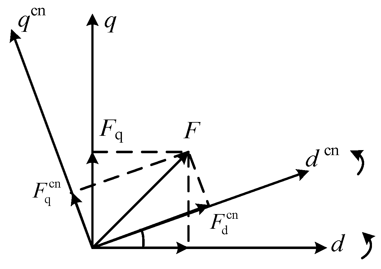
Owing to the control effect of the PLL, the main circuit coordinate system and the control system, and the relationship between the two coordinate systems is shown in Figure 3. The d-axis and q-axis constitute the primary circuit coordinate system, with Fd and Fq representing the projections of vector F onto the d-axis and q-axis, respectively. Correspondingly, the dcn-axis and qcn-axis form the control system coordinate system, with Fdcn and Fqcn denoting the projections of vector F onto the dcn-axis and qcn-axis, respectively. ω1 represents the fundamental angular frequency of the grid voltage. The control system coordinate system rotates with an angular velocity of ωPLL, and the phase angle difference between them is θPLL. Under steady-state conditions, the phase angle difference between the primary circuit dq coordinate system and the control system dq coordinate system is zero. However, when the PLL is subjected to small-signal disturbances, the θPLL will no longer be zero. Figure 4 illustrates the control structure of PLL.
The relationship between the small-signal disturbance component Δvqcn on the q-axis of the voltage at the PCC of the converter and the small-signal disturbance component ΔθPLL arising from the phase angle difference in the PLL can be expressed as:
Δ θ PLL = Δ v q cn k pPLL + k iPLL s 1 s
where kpPLL and kiPLL represent the proportional and integral constants of the proportional–integral controller in the PLL, respectively. The expression for the phase angle error can be correspondingly represented as follows.
Δ θ PLL = s k pPLL + k iPLL s 2 + s V d k pPLL + V d k iPLL Δ v q = G PLL Δ v q
Furthermore, considering the relationship between the disturbance components of the converter’s output AC current and the duty cycle signal in different rotating speed coordinate systems, the transfer function of the PLL can be derived as follows:
G P L L i = 0 I q G P L L 0 I d G P L L , G P L L d = 0 D q G P L L 0 D d G P L L , G P L L = s k pPLL + k iPLL s 2 + s V d k pPLL + V d k iPLL
where Id and Iq represent the projections of the steady-state three-phase AC current output by the grid-connected converter and Dd and Iq represent the projections of the duty cycle signal in the dq coordinate system of the primary circuit. From (2), it can be inferred that small-signal disturbance components in the primary circuit can penetrate the control system through the PLL, thereby adversely affecting system stability.

2.2.2. Model of Voltage Controllers and Current Controllers

For the voltage controller, the relationship between the input voltage disturbance ΔVdc on the DC side of the grid-connected converter and the disturbances in the DC-side current Δidc and AC-side current Δi can be expressed as follows:
Δ V dc = 1 s C dc Δ i dc 0 3 4 s C dc I d I q 0 0 Δ d d Δ d q 3 4 s C dc D d D q 0 0 Δ i d Δ i q = 1 s C dc Δ i dc G d c d Δ d G d c i Δ i
where Gdcd represents the transfer function matrix between the DC-side voltage and the duty cycle signal of the converter under small-signal disturbances; Gdci represents the transfer function matrix between the DC-side voltage and the AC-side current; and Id and Iq are the steady-state values of the AC current signals.
Δ i d Δ i q = s L LC + R LC w 1 L LC w 1 L LC s L LC + R LC 1 V dc 2 Δ d d Δ d q Δ v d Δ v q + 1 2 D d 0 D q 0 Δ V dc 0 = Y o u t Δ d Y i n Δ v + Y d c Δ V d c
where Yout represents the transfer function matrix between the AC current and the steady-state values Dd and Dq of the duty cycle signal, Yin represents the transfer function matrix between the AC current and the AC voltage, and Ydc represents the transfer function matrix between the AC current and the DC-side input voltage ΔVdc.
According to the transfer function models of the control loops, multiple coupling effects exist between the control loops and the control parameters for the AC-side output current Δi and the DC-side voltage ΔVdc of the grid-connected converter. These coupling characteristics are reflected in the impedance characteristics of the grid-connected converter port.
Figure 5 presents a small-signal control block diagram derived from the relationship between the input voltage and current and the output voltage and current of the grid-connected converter. The relationship between variables in the main circuit and control circuit is displayed, from which the overall impedance model of the grid-connected converter can be derived [32].
In Figure 5, Path 1 and Path 2 are, respectively, phase-locked loop effect paths, Path 3 is a current inner loop control structure, and Path 4 is a voltage outer loop control structure. voltage and current symbols with superscripts “ G d e c ” denote input and output variables in the dq coordinate system of the control system, whereas those without superscripts “ G d e c ” represent input and output variables in the dq coordinate system of the main circuit. The transfer function matrices Gcv and Gci represent the equivalent transfer functions of the proportional–integral controllers in the voltage loop and current loop, respectively. Gdec is the decoupling term in the current control loop, Gdcv is the transfer function that normalizes the modulation wave, Gsd is the equivalent transfer function of the delay element in SPWM control, GPLLd and GPLLi are the equivalent transfer functions of the control paths in the PLL, and Gdcc is the transfer function matrix between the DC-side voltage and current. The specific expressions of these transfer functions for different control loops are shown in (6). Since the primary objective of this article is to propose a stability analysis method for each control loop, the detailed derivation process of the overall impedance model of the grid-connected converter is not presented here.
G d e c = 0 w 1 L w 1 L 0 , G d c v = 2 / V dc 0 0 2 / V dc G s d = e s T d 0 0 e s T d   , G d c c = 1 / s C dc 0 0 1 / s C dc

2.3. Modelling for Integrating Multiple Grid-Connected Converters into Systems Based on Network Node Impedance

Based on the impedance modelling of a single grid-connected converter, a network node impedance modelling approach for systems incorporating multiple grid-connected converters is developed. This model aims to analyze the coupling effects between grid-connected converters and the power grid, as well as among different grid-connected converters, providing a theoretical foundation for stability studies of systems with multiple grid-connected converters.
To enhance the generality of the results, the equivalent simplifications on the system with multiple grid-connected converters are first performed. Assume that there is a total of n nodes in the system, with m nodes connected to converters, la-belled Con1, Con2, Con3, …, Conm. In the dq coordinate system, Norton’s theorem can be applied to equivalently represent the converters and the grid as current sources in parallel with grid impedance. The equivalent circuit of the system at this point is shown in Figure 6. Vj, Vm represent the voltages at the parallel nodes of the grid-connected converters and the grid at different locations. Is,j, Is,m denote the equivalent power source currents of the grid-connected converters. Io,j, Io,m represent the outlet currents on the grid side of the grid-connected converters. The electrical equipment in the power system, such as transformers, transmission lines, compensation devices, and filters, is equivalently represented via RLC circuits, i.e., Rgr,n, Lgr,n, Cgr,n, and other components.
Assuming that the fundamental frequency of the grid is ω1, under a three-phase balanced state, the equivalent admittance YsC of the capacitive elements and the equivalent impedance of the resistive-inductive elements in the system, after dq coordinate transformation, can be expressed as (7) and (8), respectively.
Y s C = s C ω 1 C ω 1 C s C
Z R + s L = R + s L ω 1 L ω 1 L R + s L
Although the stability of a single grid-connected converter can be relatively easily achieved, when multiple grid-connected converters are integrated into a system, the instability of one device may trigger oscillations or even instability throughout the entire system. Therefore, it is necessary to assess the stability of systems with multiple grid-connected converters.
Considering the superposition principle, an equivalent network node impedance model for systems with multiple grid-connected converters is established. In the dq coordinate system, by setting the equivalent current sources in the grid to zero (i.e., Igr,n = 0), the relationship between the node voltages and the currents flowing through the nodes in the system with the converters connected can be expressed as (9) [19].
I in = Y in V x = Y 11 Y 1 k Y 1 n Y k 1 Y kk Y kn Y n 1 Y nk Y nn V 1 V k V n
where the injected node current is the current in the dq coordinate system, denoted as Iin = [Id,in, Iq,in]T. Similarly, the node voltage Vx is represented as Vx = [Vd,x, Vq,x]T. Yin represents the node admittance matrix of the system in a common coordinate system when the equivalent current sources in the system are set to zero. It is a 2n × 2n square matrix.
According to the superposition theorem, under normal system operation, the expression for the node voltage matrix Vcon of the nodes with converters connected is given by (10).
V con = V conx + V cony = I o Z m + I gr Z gr
where Vcon represents the node voltage matrix composed of the nodes connected to the grid-connected converters, i.e., Vcon = [V1, …, Vk, …, Vn]T.
The node-injected current Iin is the output current on the side of the converters connected to the grid. The relationship between Iin and the equivalent current source Is of the converters can be expressed as (11).
I in = I o = I s Y conx V con
where Io = [Io,1, …, Io,k, …, Io,m]T, where Io,k = [Iod,k, Ioq,k]T. Yconx is a 2n × 2n matrix composed of the equivalent output admittances of all converters, satisfying Yconx = diag(Ycon,1,…, Ycon,m,…, Ycon,n). Io, Vcon, and Yconx are all matrices in the dq coordinate system.
By combining (10) and (11) and eliminating the intermediate variable Vcon, the output current Io of the converters connected to the grid can be obtained as
I o = ( I + Y conx Z m ) 1 ( I s Y conx I gr Z gr )
where I denote the 2n × 2n identity matrix.
Therefore, the stability analysis problem of a system with multiple grid-connected converters can be transformed into a stability analysis problem of a multi-input multioutput (MIMO) system. In this context, Is and Igr are the small-signal disturbance input variables, whereas Io is the system output variable. The stability of the output variable is closely related to variables such as Yconx and Zm. Yconx is a diagonal matrix composed of the equivalent output admittance of the converters. As long as each converter remains stable, Yconx will have no poles in the right half-plane. The grid-side impedance Zm is composed of passive components in the power system and inherently does not have poles in the right half-plane. Therefore, the stability of this MIMO system is solely related to (I + YconxZm)−1. The open-loop transfer function Lm can be expressed as (13).
L m = Y conx Z m
Using the Nyquist criterion, it is determined that the necessary and sufficient condition for the stability of a system with multiple grid-connected converters is that the Nyquist plot of the eigenvalues of Lm does not enclose the point (−1, j0) in the complex plane. The transfer function matrix Lm is different from the traditional impedance analysis method to judge the system stability. The traditional impedance analysis method requires complete re-modeling when the network topology changes. The proposed network node impedance model only requires minor adjustment of several elements in the impedance matrix. This significantly improves the efficiency of stability analysis for complex systems with multiple access points.
By modelling the control loop of a single grid-connected converter and the system with multiple grid-connected converters, the stability of the control loop of the grid-connected converter and the stability of the system with multiple grid-connected converters can be assessed. A detailed analysis is presented in the subsequent sections.

3. Stability Analysis of Control Loop for Grid-Connected Converters

3.1. Analysis of the Impact on Current Loop of Grid-Connected Converters

The control system of grid-connected converters encompasses multiple control loops, including the voltage loop, current loop, and PLL. Ensuring the stability of each control loop is fundamental to maintaining the overall system stability. Therefore, this article delves into the stability analysis of these control loops.
By simplifying the control section with an inner current loop in Figure 4, the small-signal control block diagram of the grid-connected converter is obtained considering the inner current loop. The control loops involving the PLL are represented by paths ① and ② in the diagram, whereas path ③ represents the control loop involving the inner current loop.
Hence, the open-loop transfer function of the small-signal model for the converter’s current loop can be derived as follows.
G oi = Y out G sd G dcv ( G ci G dec ) G ci = k pi + k ii s , 0 ; 0 , k pi + k ii s
where Gci represents the transfer function of the current loop PI controller.
According to the generalized Nyquist criterion, the control loop is stable when the Nyquist curves of all the eigenvalues of the open-loop transfer function matrix Goi of the current loop do not enclose the point (−1, j0) in the complex plane. Equation (14) shows that the stability of the grid-connected converter’s current loop is closely related to factors such as the filter resistance RLC, inductance LLC, time delay constant Td, proportional–integral coefficients kpi and kii in the current controller, and decoupling parameters in the current controller. For the filter circuit, increasing the filter inductance L can enhance the converter’s stability. However, when the inductance increases beyond a certain range, excessively large inductance values can slow down the circuit’s dynamic response and reduce energy transmission efficiency. In practical engineering, owing to limitations such as installation space and economic considerations, adjusting the filter inductance to regulate the stability margin of the grid-connected converter is less common. Therefore, the improvement in grid-connected converter stability is achieved primarily by modifying control parameters such as Td, kpi, and kii.
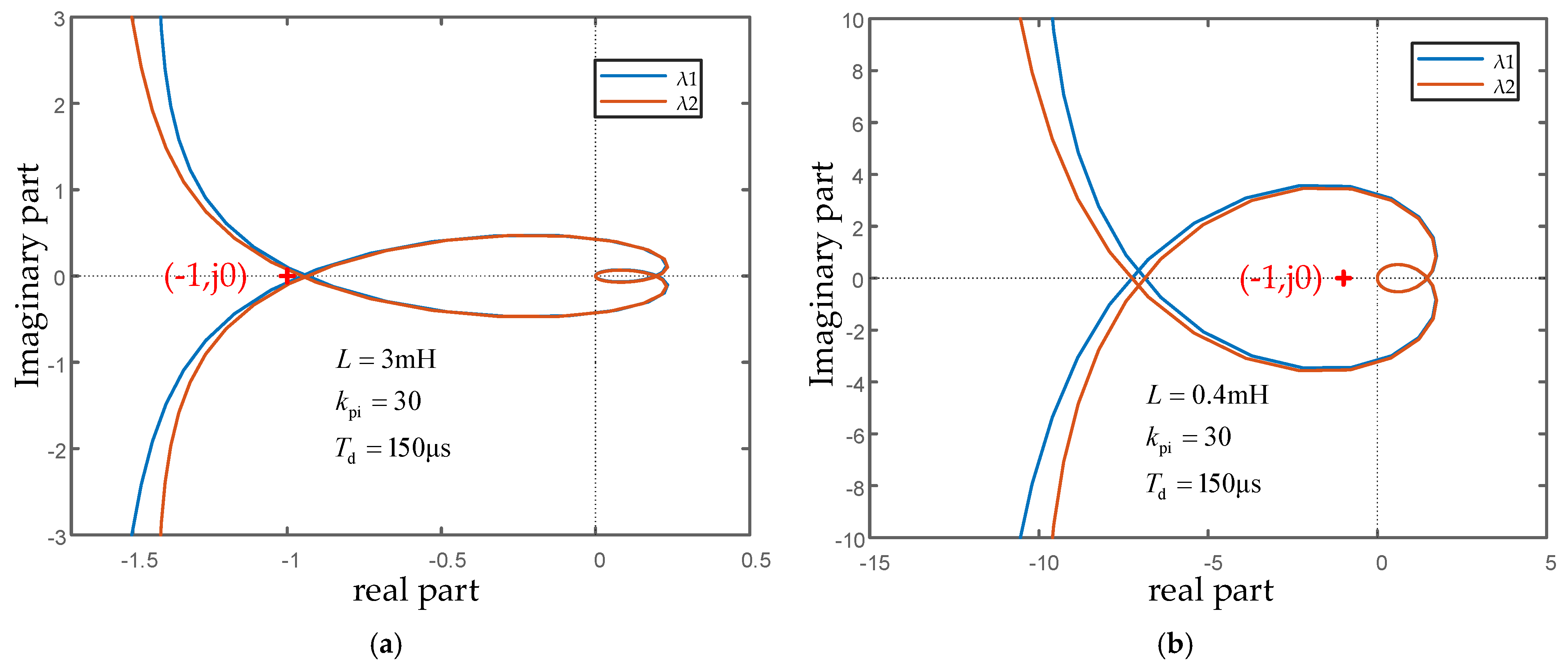
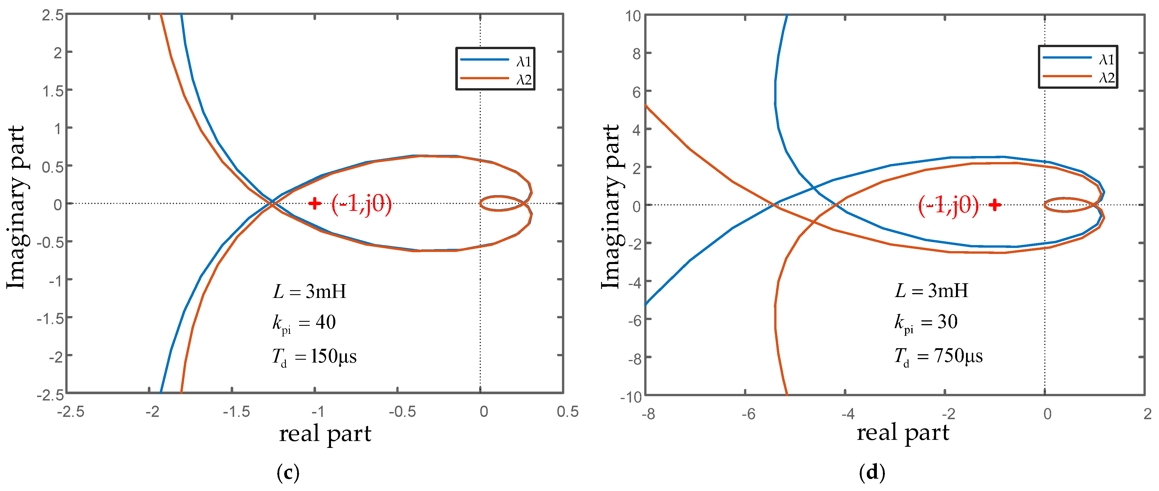
Figure 7 shows the Nyquist curves of the eigenvalues of the open-loop transfer function of the current loop when the filter inductance, proportional gain of the current controller and the time delay parameter are varied. In Figure 7, decreasing the filter inductance L of the current controller from 3 mH to 0.4 mH, increasing the proportional gain kpi of the current controller from 30 to 40 or increasing the time delay Td from 150 μs to 750 μs can lead to system instability. Therefore, the filter inductance, proportional gain and time delay should be controlled within reasonable ranges to avoid instability issues.

3.2. Analysis of the Impact of the Phase-Locked Loop on Grid-Connected Converters

There is a loop representing the positive feedback path introduced by the PLL control structure. Yconi denotes the equivalent admittance of the converter, and its expression is given by:
Y coni = Δ i Δ v = G cli ( Y out G sd G pllz Y in )
where I represent the second-order identity matrix and Gcli denotes the closed-loop transfer function of the inner current loop, which is expressed as follows:
G cli = ( I + G oi ) 1
Owing to the use of SPWM technology in the converter, under steady-state conditions, the relationship between the voltage and current at the PCC satisfies (17).
D d V dc 2 = V d + R LC I d w 1 L I q D q V dc 2 = R LC I q + w 1 L I q
When the inner current loop remains stable, Gcli does not possess poles in the right-half plane. In this scenario, the expression for the PLL transfer function Gpllz should satisfy:
G pllz = G PLLd G dcv ( G ci G dec ) G PLLi
If (YoutGsdGpllz-Yin) does not have poles in the right-half plane, both the inner current loop and the PLL of the grid-connected converter can maintain stability. Neglecting the equivalent internal resistance of the filter, i.e., setting RLC = 0, it can be obtained as
Y out G sd G pllz = e s T d G P L L ( s L ) 2 + ( w 1 L ) 2 0 s L G ci I q + w 1 L ( V d + G ci I d ) 0 w 1 L G ci I q + s L ( V d + G ci I d )
The above equation has two eigenvalues, λ1 and λ2, with the following values:
λ 1 = 0 λ 2 = w 1 L G ci I q + s L ( V d + G ci I d )
Figure 8 presents Nyquist plots of the eigenvalues for the grid-connected converter system in both the rectifying mode (Idref < 0) and inverting mode (Idref > 0). Specifically, when Idref < 0, the eigenvalue λ2 shifts towards the left-half plane, making it easier to enclose the point (−1, j0) in the complex plane, thereby reducing the stability of the grid-connected converter. Conversely, when Idref > 0, the Nyquist curve of the eigenvalue λ2 shifts towards the right-half plane compared with the curve in the rectifying mode, moving away from the point (−1, j0) in the complex plane and thus enhancing the stability of the grid-connected converter.
To quantify the effectiveness of our proposed method, we compared it with traditional eigenvalue-based methods. Traditional methods often require complex state-space models and struggle with scalability in multi-converter systems [28]. In contrast, our impedance-based approach simplifies the analysis by directly linking control parameters to stability margins. For example, our method can detect instability at a 33% increase in kpi (from 30 to 40) with a precision of ±5%, whereas traditional methods may fail to detect such changes due to their computational complexity and sensitivity to model order [28]. This highlights the superior accuracy and computational efficiency of our proposed method, making it more suitable for practical applications in complex grid-connected systems.
Through the analysis of the current control loop and phase-locked loop, it derives that various factors, including the proportional coefficient of the current controller, time delay, filter impedance, grid impedance, and power transmission direction, can potentially impact the stability of grid-connected converters. The proposed method simplifies the analysis process and provides a more intuitive understanding of parameter influence patterns. This is achieved by deriving the open-loop transfer functions of each control loop from the control block diagram to analyze the stability of the control loops.

4. Stability Analysis of Renewable Energy Systems Incorporating Multiple Grid-Connected Converters

Based on (15), the criteria for assessing the stability of a system with multiple grid-connected converters are as follows. First, the eigenvalues of the gain matrix Lm = YconxZm are calculated, and the Nyquist curves for all the eigenvalues are plotted. If none of the Nyquist curves enclose the point (−1, j0) in the complex plane, the system can be deemed stable; otherwise, it is considered unstable.
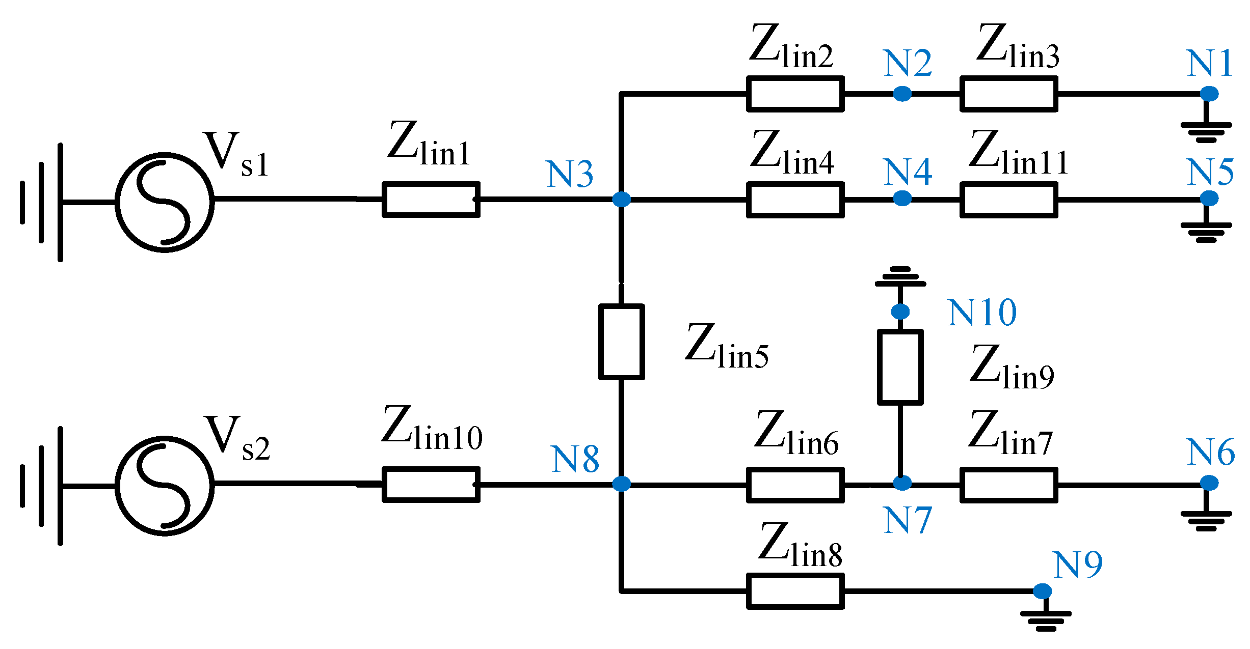
To validate the proposed theory for stability analysis of multiple grid-connected converters, this article conducts an empirical study using a system with four grid-connected converters as an example. Figure 9 presents a schematic diagram of the topology of the system with four grid-connected converters. Among them, Con1, Con2, and Con3 are connected at fixed positions, whereas Con4’s position is varied to analyze the impact of the network impedance matrix on system stability at different connection points. Nodes N1–N13 in the diagram represent various points in the system. Combining Figure 9 with the network node impedance modelling method, the calculation models for Yconx and Zm can be derived as shown in (21) and (22), respectively.
Where Yconx,1, Yconx,2, Yconx,3, and Yconx,4 represent the equivalent output admittances of the four grid-connected converters, respectively, and their calculation methods are given in the formula. Zm,ij denotes the impedance matrix element between node i and node j, with the subscript k indicating the connection point of the grid-connected converter Con4. In this article, the possible connection points are k = 1, 2, 4, 5, 6, 7, and 8.
Y conx = Y conx , 1 0 0 0 0 Y conx , 2 0 0 0 0 Y conx , 3 0 0 0 0 Y conx , 4
Z m = Z m , 3   3 Z m , 3   9 Z m , 3   10 Z m , 3   k Z m , 9   3 Z m , 9   9 Z m , 9   10 Z m , 9   k Z m , 10   3 Z m , 10   9 Z m , 10   10 Z m , 10   k Z m , k   3 Z m , k   9 Z m , k   10 Z m , k   k
Since the impedance models in (21) and (22), in conjunction with (15), the stability of a system with multiple grid-connected converters can be assessed by calculating the eigenvalues of the open-loop transfer function Lm. Table 2 shows the results of the system stability analysis when converter 4 is not connected in parallel with other converters. From Table 2 it can be concluded that the system will be unstable when converter 4 is connected to N1 and N7. The following is a detailed analysis of the system stability when the converter is connected to N6 and N7. Figure 10 and Figure 11 present the Nyquist curves of the eigenvalues of the open-loop transfer function Lm when converter Con4 is connected to nodes N6 and N7, respectively.
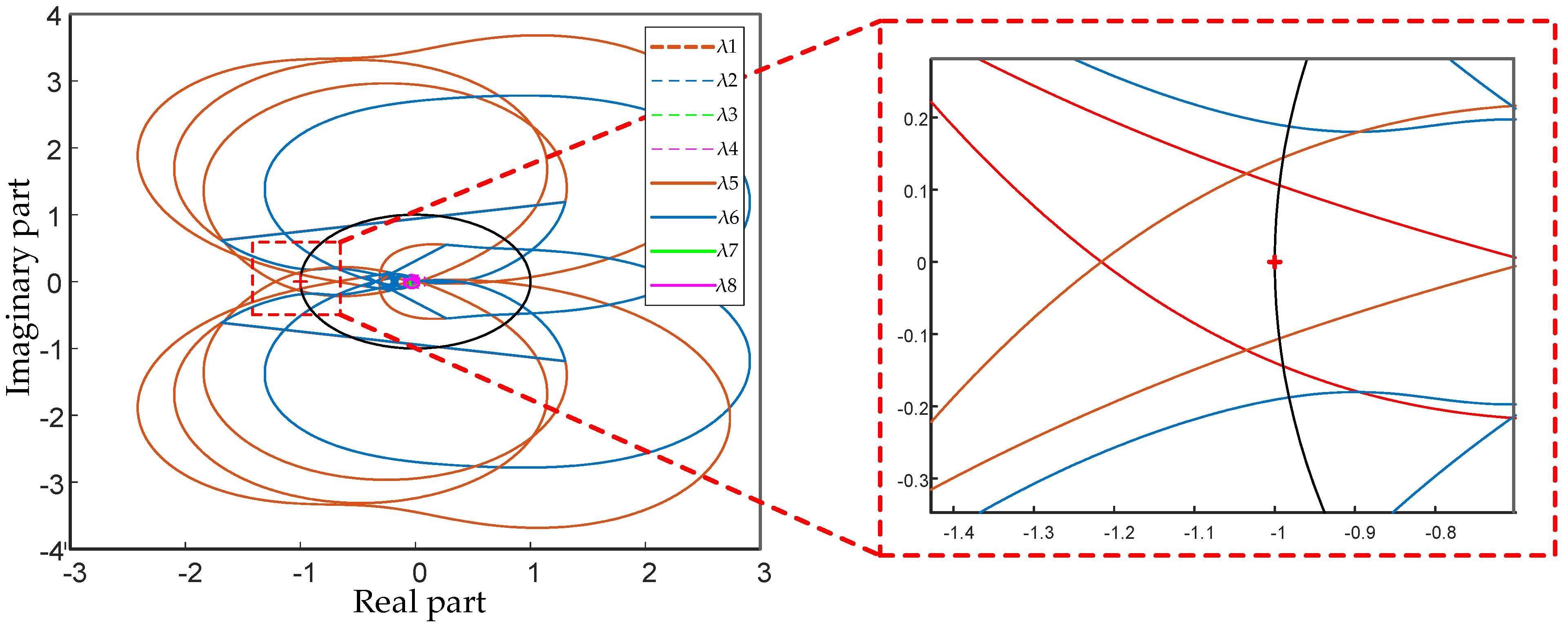
Specifically, Figure 10 shows that when Con4 is connected to node N6, none of the Nyquist curves of the eigenvalues of Lm enclose the point (−1, j0), indicating that Lm has no right-half-plane poles and that the system is stable. However, Figure 11 reveals that when the connection point of the grid-connected converter changes to N7, one of the eigenvalues of Lm (specifically, eigenvalue λ5) encloses the point (−1, j0) in the complex plane, suggesting that Lm has right-half-plane poles and that the system is unstable.
It can be seen that the converter 4 access nodes 1 and 7 are the leading factors causing the system instability, and the system instability source positioning is realized. Therefore, different connection points of the grid-connected converter can alter the grid-side circuit topology and equivalent impedance model, thereby affecting the stability of the system.

5. Case Verification

To verify the accuracy and effectiveness of the stability analysis results presented in this article for both the control loop of a grid-connected converter and the system with multiple grid-connected converters, corresponding simulation models are constructed in the MATLAB R2024a/Simulink environment. The simulation models were designed to closely mimic real-world power systems, incorporating realistic parameters and operating conditions. The results of these simulations provide strong evidence of the models’ validity and their potential for practical application in actual systems. Specifically, the topology and control strategy of a single grid-connected converter remain consistent with those shown in Figure 2, whereas the overall topology of the system with multiple grid-connected converters is consistent with that shown in Figure 9. This case system refers to the structure of the IEEE 13 node model [33]. The parameters used in the simulation process are detailed in Table 3 and Table 4. The parameters used in the simulation process are shown in Table 3 and Table 4. These parameters are set according to the industry standard of the grid-connected inverter PI adjustment guide and the typical parameter Settings obtained from experimental tests. They have certain practical significance and are not explained too much here.
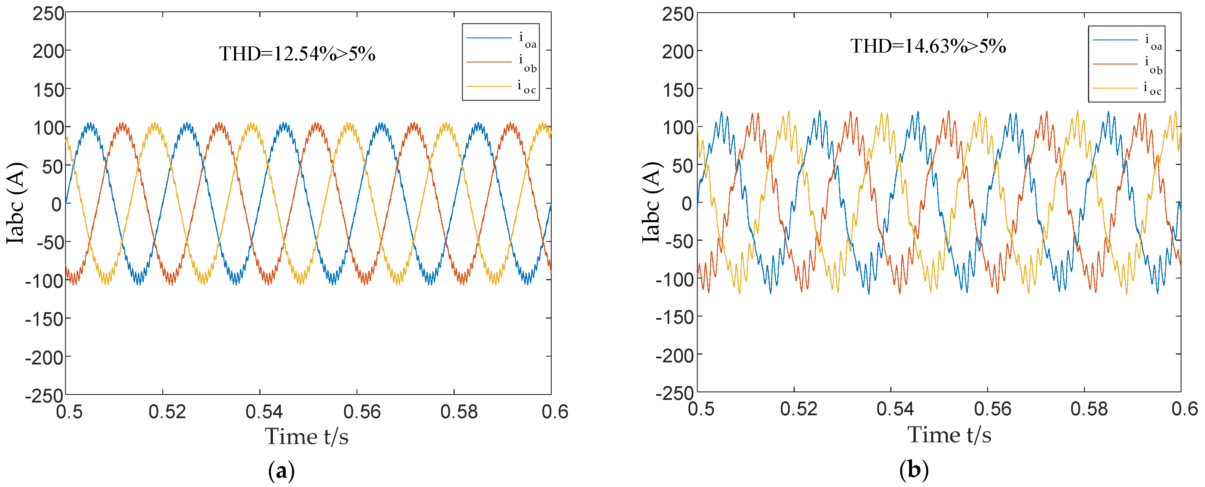
Figure 12 and Figure 13 show the simulation results of stability analysis of the single converter system. the stability analysis results of the current control loop are verified. Figure 12 presents the simulation results under two conditions: increased proportional gain of the current control loop (Figure 12a), and increased time delay constant (Figure 12b). The changes in the parameters are consistent with those shown in Figure 7. The simulation results indicate that as the proportional gain of the current control loop and the time delay increase, the system becomes unstable, which aligns with the analysis results of the theoretical model, thereby validating the correctness of the theoretical analysis.
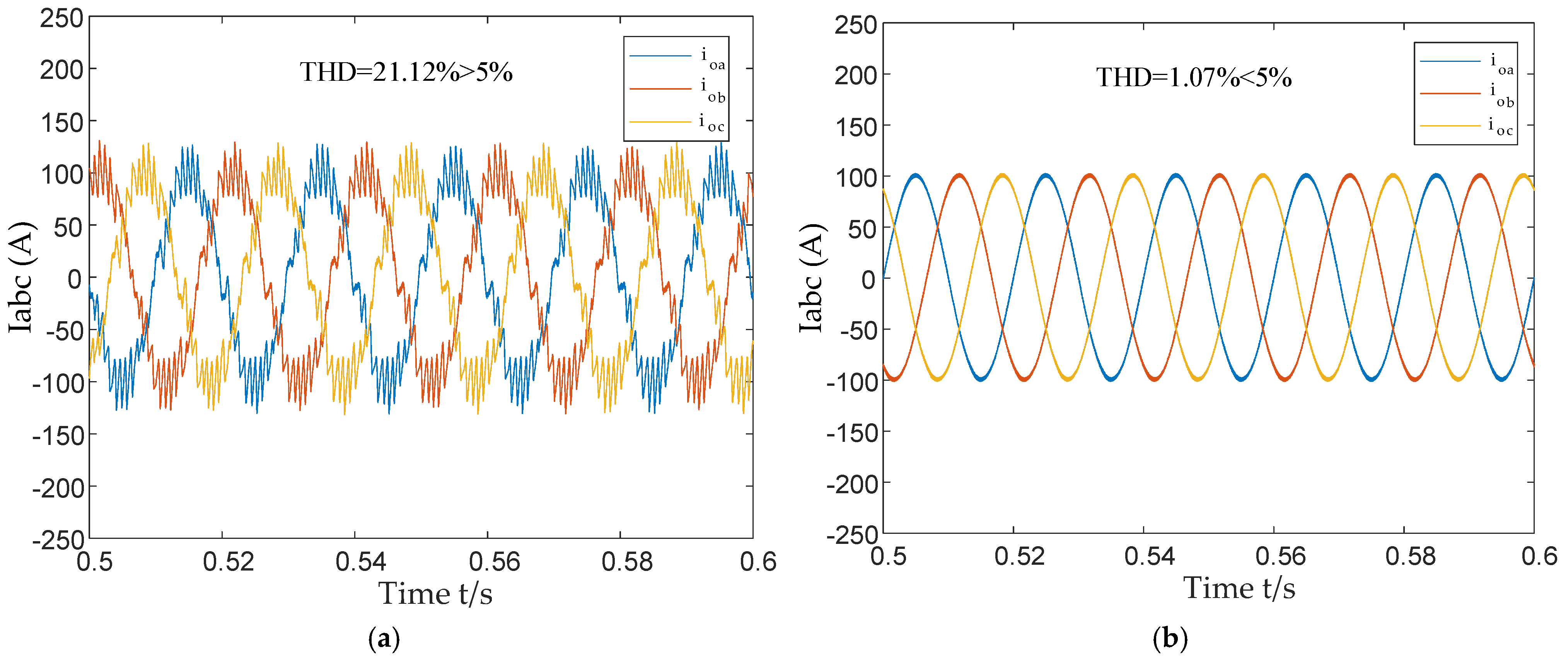
The results of PLL stability analysis are validated. Figure 13 presents the simulation results under two conditions: when the current reference value Idref is less than zero and when it is greater than zero. When Idref is less than zero, the current waveform at the point of common coupling exhibits significant oscillations, indicating that the system is in an unstable state. This aligns with the theoretical analysis results shown in Figure 8a. Conversely, when Idref is greater than zero, the current at the point of common coupling operates stably, which is consistent with the theoretical analysis results shown in Figure 8b. These simulation results verify the correctness of the PLL stability analysis.
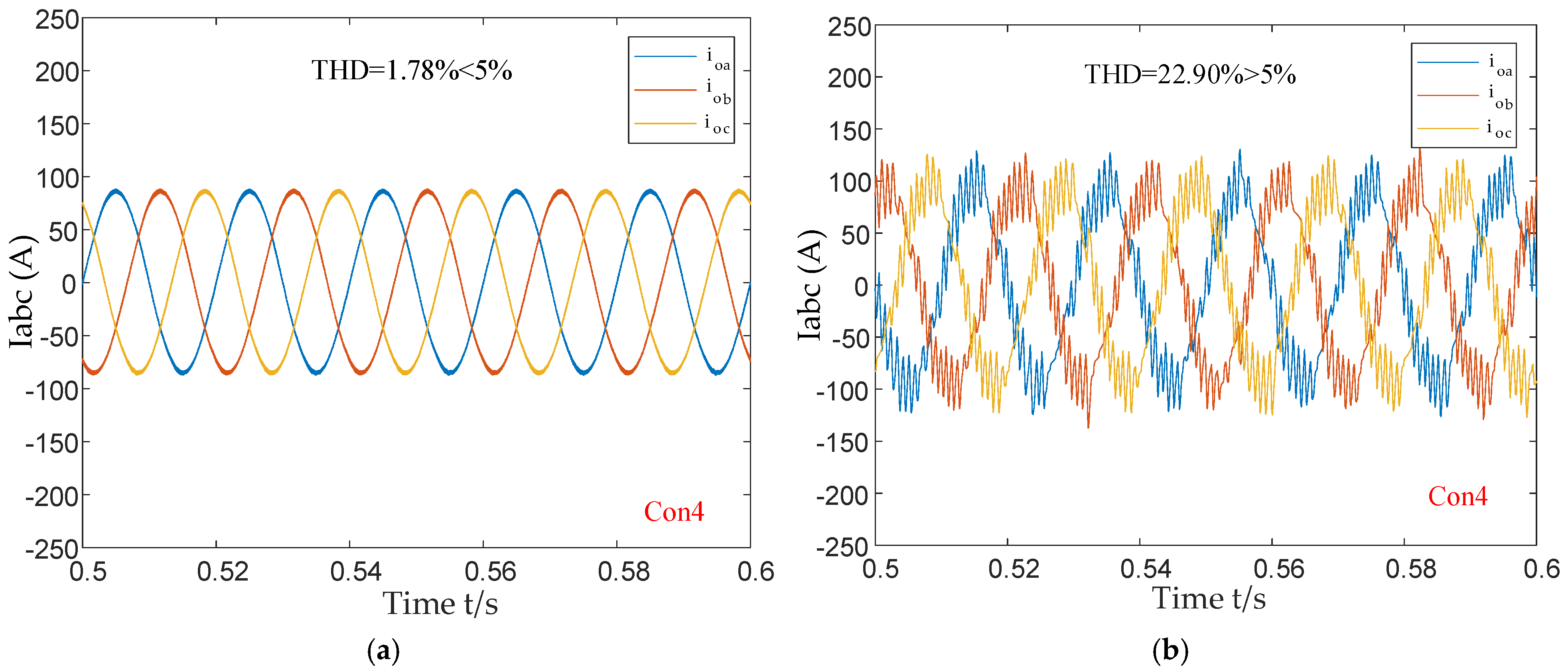
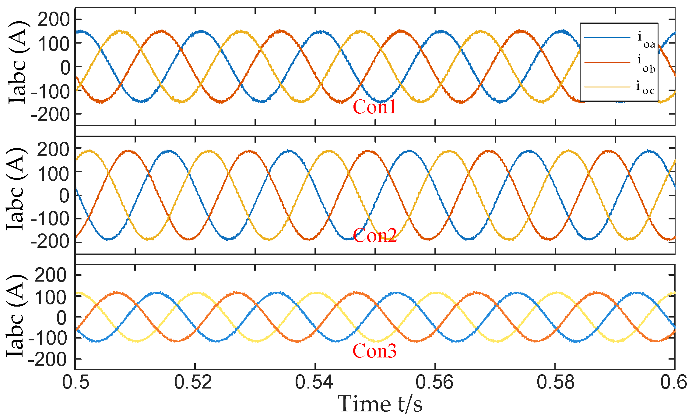
Figure 14 and Figure 15 shows the simulation results for the stability analysis of the multi-converter system. The results of the stability analysis for a system with multiple parallel-connected converters are validated. Figure 14a displays the current waveform at the PCC when converter Con4 is connected to node N6, with the current waveform remaining stable. However, when converter Con4 is instead connected to node N7, as shown in Figure 14b, the PCC waveform of converter Con4 exhibits significant harmonic distortion (THD = 9.25%), indicating that the system is in an unstable state. This aligns with the theoretical analysis results presented in Figure 11, thereby validating the effectiveness of the proposed stability analysis method for systems with multiple grid-connected converters. From Figure 15, it can be concluded that when converter 4 is connected to the node 7, the remaining three converters can still output stable three-phase current waveform, and only converter 4 has high-frequency oscillation, so it can be judged that converter 4 is the source of instability.
Hence, the stability analysis results for both individual grid-connected converters’ control loops and the systems with multiple grid-connected converters are in good agreement with the simulation results, demonstrating the validity of the proposed model.

6. Conclusions

A detailed impedance model of the grid-connected converter was developed. Based on this model, a simple and highly accurate stability analysis expression was derived and an in-depth analysis of the instability mechanisms and stability influencing factors of individual control loops in direct-drive grid-connected converters was conducted. Furthermore, the stability of systems with multiple grid-connected converters was explored. The main research conclusions include the following:
(1) By modelling and analyzing the current loop and PLL of grid-connected converters individually, the influence patterns of various control loop parameters on stability are revealed. Specifically, within a certain range, reducing the filter inductance L, increasing the current control proportional coefficient kpi, increasing the digital delay time constant Td and adjusting the power direction Idref will all lead to a decrease in system stability or even instability.
(2) Based on the small-signal impedance model of the multi-converter system established using the nodal admittance matrix, a simple and easily solvable loop gain matrix Lm was obtained. Through Lm, the stability of the system can be judged more accurately and quickly. It was found that changes in the connection points of grid-connected converters lead to variations in the network node impedance matrix, which in turn affects system stability. By adjusting certain parameters in the grid-side matrix of the proposed model, the stability of the system under different node connections can be analyzed, simplifying the analysis process. Even when the system topology changes frequently, the reconstruction or modification of the stability analysis model involving some elements in Lm is convenient and fast, significantly improving the efficiency of analyzing the stability of distribution systems.
However, the small-signal modelling method used in this article only discusses scenarios where multiple converters of the same type are connected to the distribution system, lacking analysis of scenarios where different types of converters are connected to the distribution system. Moreover, the proposed stability analysis method still has certain limitations in weak current networks with high harmonic distortion. Future work will focus on in-depth research on modelling methods for various types of power electronic converters, while expanding and improving relevant models to enhance the accuracy of stability analysis under different operating conditions.

Author Contributions

Conceptualization, L.H.; Methodology, D.L. and J.R.; Software, Y.S.; Validation, L.H., D.L. and Y.S.; Formal analysis, Y.W. and Y.X.; Investigation, H.T.; Data curation, J.R. and J.L.; Writing – original draft, L.H.; Visualization, Y.W.; Project administration, J.L. and Y.X.; Funding acquisition, J.R. All authors have read and agreed to the published version of the manuscript.

Funding

This research was funded by the Research Project of China Three Gorges Corporation Limited, grant number NBZZ202300679.

Data Availability Statement

The original contributions presented in this study are included in the article. Further inquiries can be directed to the corresponding author.

Conflicts of Interest

Authors Lifu He, Yangwu Shen, Jiapeng Ren and Yuting Wang were employed by the company China Three Gorges Corporation. Authors Jin Li and Yaqin Xu were employed by the company Three Gorges Intelligent Engineering Co., Ltd. The remaining authors declare that the research was conducted in the absence of any commercial or financial relationships that could be construed as a potential conflict of interest.

References

  1. Mao, L.; Huang, Y.; Zhao, J.; Zeng, Z. Suppression and stability analysis of positive feedback effect of phase-locked loop in grid connected inverters under weak power grid. Int. J. Electr. Power Autom. Equip. 2025, 4, 1–13. [Google Scholar]
  2. Gao, B.; Liu, Y.; Shao, B.; Ran, H. A path analysis method to study the sub-synchronous oscillation mechanism direct-drive wind farm with VSC-HVDC system. Int. J. Electr. Power Energy Syst. 2023, 43, 6646–6660. [Google Scholar]
  3. Bakhshizadeh, M.K.; Ghosh, S.; Yang, G.; Kocewiak, Ł. Transient Stability Analysis of Grid-Connected Converters in Wind Turbine Systems Based on Linear Lyapunov Function and Reverse-Time Trajectory. J. Mod. Power Syst. Clean Energy 2024, 12, 782–790. [Google Scholar] [CrossRef]
  4. Du, W.; Dong, W.; Wang, H.; Cao, J. Dynamic aggregation of same wind turbine generators in parallel connection for studying oscillation stability of a wind farm. IEEE Trans. Power Syst. 2019, 34, 4694–4705. [Google Scholar] [CrossRef]
  5. Li, Y.; Fan, L.; Miao, Z. Wind in weak grids: Low-frequency oscillations, sub-synchronous oscillations, and torsional interactions. IEEE Trans. Power Syst. 2020, 35, 109–118. [Google Scholar] [CrossRef]
  6. Li, G.; Chen, Y.; Luo, A.; Liu, X. Wideband Harmonic Voltage Feedforward Control Strategy of STATCOM for Mitigating Subsynchronous Resonance in Wind Farm Connected to Weak Grid and LCC HVDC. IEEE Trans. Emerg. 2021, 9, 4546–4557. [Google Scholar] [CrossRef]
  7. Shao, B.; Zhao, S.; Gao, B.; Yang, Y.; Blaabjerg, F. Adequacy of the single-generator equivalent model for stability analysis in wind farms with VSC-HVDC systems. IEEE Trans. Energy Convers. 2021, 36, 907–918. [Google Scholar] [CrossRef]
  8. Xu, Y.; Zhang, M.; Fan, L.; Miao, Z. Small signal stability analysis of type-4 wind in series compensated networks. IEEE Trans. Energy Convers. 2020, 35, 529–538. [Google Scholar] [CrossRef]
  9. Du, W.; Ren, B.; Wang, H.; Wang, Y. Comparison of methods to examine sub-synchronous oscillations caused by grid-connected wind turbine generators. IEEE Trans. Power Syst. 2019, 34, 4931–4943. [Google Scholar] [CrossRef]
  10. Wang, L.; Zeng, S.; Feng, W.; Prokhorov, A.V.; Mokhlis, H.; Huat, C.K.; Tripathy, M. Damping of Subsynchronous Resonance in a Hybrid System with a Steam-Turbine Generator and an Offshore Wind Farm Using a Unified Power-Flow Controller. IEEE Trans. Ind. Appl. 2021, 57, 110–120. [Google Scholar] [CrossRef]
  11. Chen, W.; Wang, P.; Li, K.; Zou, R.; Tian, S.; Yu, H. Forced Subsynchronous Oscillations of Turbine-Generators Excited by Interharmonics from Bundled Offshore Wind Farms. IEEE Trans. Power Syst. 2024, 39, 5416–5430. [Google Scholar] [CrossRef]
  12. Yu, J.; Ouyang, J.; Zhang, A.; Chen, J. Modeling of Dynamic Control Error and Emergency Frequency Control for Direct-Drive PMSG-Based Wind Turbine Under Grid Fault. IEEE Trans. Sustain. Energy. 2024, 15, 1690–1702. [Google Scholar] [CrossRef]
  13. Yu, J.; Wang, S.; Liu, Z.; Li, J.; Liu, J.; Shang, J. Accurate Small-Signal Terminal Characteristic Model and SISO Stability Analysis Approach for Parallel Grid-Forming Inverters in Islanded Microgrids. IEEE Trans. Power Electron. 2023, 38, 6597–6612. [Google Scholar] [CrossRef]
  14. Jiang, K.; Ji, X.; Liu, D.; Zheng, W.; Tian, L.; Chen, S. Small-Signal Modeling of Grid-Forming Wind Turbines in Active Power and DC Voltage Control Timescale. Electronics 2024, 13, 4728. [Google Scholar] [CrossRef]
  15. Tang, H.; Wang, J.; Wu, C.; Wang, Y. Effect of Coupling Impedance on Stability Assessment of Grid-Forming Converters Under Various Grid Conditions. Electronics 2024, 13, 4382. [Google Scholar] [CrossRef]
  16. Arshad, M.; Beik, O.; Pallapati, R.; Hoberg, S. Overview and Impedance-Based Stability Analyses of Bison Wind Farm: A practical example. IEEE Ind. Appl. Mag. 2024, 30, 50–63. [Google Scholar] [CrossRef]
  17. Qin, S.; Wang, P.; Li, S.; Zhao, H.; Wang, J.; Luo, J. Stability Region Assessment with Mechanism-Data Driven Equivalent Impedance for Wind Power Plant. IEEE Trans. Power Electron. 2024, 39, 9355–9366. [Google Scholar] [CrossRef]
  18. Mu, H.; Yang, D.; Sun, Y.; Larumbe, L.B. Dynamic Power Tracking Performance and Small Signal Stability Analysis of Integrated Wind-to-Hydrogen System. IEEE Trans. Sustain. Energy. 2024, 15, 2444–2456. [Google Scholar] [CrossRef]
  19. Li, Y.; Shuai, Z.; Liu, X.; Chen, Y.; Li, Z.; Hong, Y.; Shen, Z. Stability Analysis and Location Optimization Method for Multiconverter Power Systems Based on Nodal Admittance Matrix. IEEE Trans. Emerg. 2021, 9, 529–538. [Google Scholar] [CrossRef]
  20. Zhang, H.; Wang, X.; Harnefors, L.; Gong, H.; Hasler, J.P.; Nee, H.P. SISO Transfer Functions for Stability Analysis of Grid-Connected Voltage-Source Converters. IEEE Trans. Ind. Appl. 2019, 55, 2931–2941. [Google Scholar] [CrossRef]
  21. Pedra, J.; Sainz, L.; Monjo, L. Three-Port Small Signal Admittance-Based Model of VSCs for Studies of Multi-Terminal HVDC Hybrid AC/DC Transmission Grids. IEEE Trans. Power Syst. 2021, 36, 732–743. [Google Scholar] [CrossRef]
  22. Henao, C.; Pepiciello, A.; Debbat, A.; Tarraso, M.; Dominguez, L.J. State Space Modeling and Small-Signal Stability Analysis of a Multiport Soft Open Point Based on the Triple Active Bridge Converter. SEST—Driving the Advances for Future Electrification. In Proceedings of the 2024 International Conference on Smart Energy Systems and Technologies, Torino, Italy, 10–12 September 2024. [Google Scholar]
  23. Wang, T.; Li, F.; Yin, C.; Jin, G. Small Disturbance Stability Analysis of Onshore Wind Power All-DC Power Generation System Based on Impedance Method. Energies 2024, 17, 1459. [Google Scholar] [CrossRef]
  24. Kwon, J.B.; Wang, X.; Blaabjerg, F.; Bak, C.L.; Wood, A.R.; Watson, N.R. Harmonic Instability Analysis of a Single-Phase Grid-Connected Converter Using a Harmonic State-Space Modeling Method. IEEE Trans. Ind. Appl. 2016, 52, 4188–4200. [Google Scholar] [CrossRef]
  25. Qian, W.; Yin, J.; Chen, Z.; Huang, X. Improved sequential impedance modeling and stability analysis of virtual synchronous generators considering frequency coupling effects. Energy Rep. 2024, 12, 2631–2641. [Google Scholar] [CrossRef]
  26. Zhu, Y.; Gu, Y.; Li, Y.; Green, T. Impedance-Based Root-Cause Analysis: Comparative Study of Impedance Models and Calculation of Eigenvalue Sensitivity. IEEE Trans. Power Syst. 2023, 38, 1642–1654. [Google Scholar] [CrossRef]
  27. Wang, F.; Zhu, S.; Liu, K.; Chen, M.; Du, Y. Impedance Modeling of Wind Turbine-Variable Speed Pumped Storage Combined Operation System. Energy Reports. 2021, 7, 470–478. [Google Scholar] [CrossRef]
  28. Li, Z.; Wang, Z.; Wang, Y.; Yin, T.; Mei, N.; Yue, B. Accurate Impedance Modeling and Control Strategy for Improving the Stability of DC System in Multiterminal MMC-Based DC Grid. IEEE Transactions on Power Electronics. 2020, 35, 10026–10049. [Google Scholar] [CrossRef]
  29. Zhang, H.; Liu, Z.; Wu, S.; Li, Z. Input Impedance Modeling and Verification of Single-Phase Voltage Source Converters Based on Harmonic Linearization. IEEE Trans. Power Electron. 2019, 34, 8544–8554. [Google Scholar] [CrossRef]
  30. Qu, K.; Liu, Y.; Liu, Z.; Zhao, J.; Zeng, Z.; Mao, L. Small-signal stability analysis and participation factor identification for multi converter DC microgrids. J. Power Electron. 2024, 39, 1–13. [Google Scholar] [CrossRef]
  31. Zhang, L.; Liu, X.; Gu, X.; Li, H.; Li, Y.; Zhang, C. Review and Prospect of Research on Frequency Safety and Stability of New Power System. Zhejiang Electr. Power. 2024, 43, 12–26. [Google Scholar]
  32. Li, Y.; Shuai, Z.; Fang, J.; Wu, X.; Shen, Z. Small-Signal Stability Analysis Method for Hybrid AC–DC Systems with Multiple DC Buses. IEEE J. Emerg. Sel. Top. Circuits Syst. 2021, 11, 17–27. [Google Scholar] [CrossRef]
  33. Kersting, W.H. Radial distribution test feeders. IEEE Trans. Power Syst. 2002, 2, 908–912. [Google Scholar]
Figure 1. Topology of a grid-connected renewable energy system via converters.
Processes 13 01292 g001
Figure 2. Typical topology of a grid-connected inverter renewable energy system.
Processes 13 01292 g002
Figure 3. The dq coordinate system of the main circuit and control system.
Processes 13 01292 g003
Figure 4. Topology of PLL.
Processes 13 01292 g004
Figure 5. Small-signal control block diagram of the grid-connected inverter.
Processes 13 01292 g005
Figure 6. Equivalent circuit for systems with multiple grid-connected converters.
Processes 13 01292 g006
Figure 7. Nyquist curves of the eigenvalues of the open-loop transfer function Goi of the current loop under different parameters. (a) Parameter setting of L, kpi, Td when the system is stabilized. (b) Reduction in the filter inductance L. (c) Increasing the proportional coefficient kpi of the current controller. (d) Increasing the time constant Td.
Processes 13 01292 g007aProcesses 13 01292 g007b
Figure 8. Nyquist curves of the eigenvalues of the phase-locked loop transfer function for different operating modes of the grid-connected. (a) Rectifying mode (unstable); (b) inverting mode (stable).
Processes 13 01292 g008
Figure 9. Topology of a renewable energy system with four grid-connected converters.
Processes 13 01292 g009
Figure 10. Nyquist plot of the eigenvalues when the grid-connected converter is connected to node N6 (stable system).
Processes 13 01292 g010
Figure 11. Nyquist plot of the eigenvalues when the grid-connected converter is connected to node N7 (unstable system).
Processes 13 01292 g011
Figure 12. Simulation results when varying the current loop parameters. (a) Current loop proportional gain increased from 30 to 40; (b) time delay increased from 150 μs to 750 μs.
Processes 13 01292 g012
Figure 13. Simulation results when varying the current reference value Idref. (a) Idref is less than zero; (b) Idref is greater than zero.
Processes 13 01292 g013
Figure 14. Simulated current waveform at the PCC for grid-connected converter Con4 connected to different nodes. (a) Connected to node N6. (b) Connected to node N7.
Processes 13 01292 g014
Figure 15. When Con4 is connected to N7, the other three converters output three-phase current waveforms.
Processes 13 01292 g015
Table 1. Comparison among typical stability analysis methods.
Analysis MethodFeature Value Analysis Method [22,23,24].Impedance Analysis Method [25,26,27,28].
Modeling PrincipleKnown system internal parameters, establish state differential equations in the time domain, obtain small-signal model through linearizationBased on system port characteristics, establish impedance model, analyze stability through equivalent impedance ratio
Stability Analysis CriteriaFeature Value CriteriaNyquist criteria
AdvantagesFully reveals the stability characteristics of system variablesCompact form, clear physical meaning, easy calculation
DisadvantagesModel order may be very high, poor scalabilityFrequency coupling increases analysis complexity; multi-input systems are difficult to divide into source-load subsystems
Applicable ScenariosSuitable for scenarios where system structure is clear, parameters are known, and model dimensions are lowSuitable for complex topologies, where equipment parameters are not fully known or rapid assessment is needed
Table 2. System stability analysis results when Con4 is connected to partial nodes.
Node NumberGM/dBPM/°
N1instability
N20.66227.6340
N40.62607.5370
N50.69597.9410
N60.68757.8440
N7instability
N80.78758.0372
Table 3. Control parameters of the grid-connected converter.
ParametersValue
Converter DC-side voltage Vdc (kV)0.8
Converter DC-side capacitance Cdc (uF)8000
Distribution grid voltage Vgr (kV)0.38
Filter inductance L (mH)3
Filter resistance RLC (Ω)0.01
Equivalent impedance of the grid Zgr0
Fundamental frequency of the distribution grid f1 (Hz)50
Sampling frequency fs (kHz)20
Proportional coefficient of the current controller kpi30
Integral coefficient of the current controller kii300
Proportional coefficient of the PLL controller kpPLL2
Integral coefficient of the PLL controller kiPLL200
Table 4. Circuit parameters of the renewable energy system.
ParametersValue
Line parametersZlin1 = 0.1293 Ω + 1.2480 mH, Zlin2 = 0.0752 Ω + 0.2454 mH
Zlin3 = 0.1254 Ω + 0.4090 mH, Zlin4 = 0.0704 Ω + 0.3651 mH
Zlin5 = 0.0100 Ω + 0.1655 mH, Zlin6 = 0.0755 Ω + 0.2438 mH
Zlin7 = 0.0755 Ω + 0.2435 mH, Zlin8 = 0.0756 Ω + 0.1346 mH
Zlin9 = 0.1203 Ω + 0.2470 mH, Zlin10 = 0.0647 Ω + 0.6293 mH
Zlin11 = 0.0100 Ω + 0.1655 mH
Load parametersZload1 = 2.6667 Ω + 16.977 mH, Zload2 = 2.6667 Ω + 33.953 mH
Zload3 = 2.6667 Ω + 11.318 mH, Zload4 = 1.3333 Ω + 4.2441 mH
Zload5 = 1.0667 Ω + 6.7910 mH, Zload6 = 1.3333 Ω + 16.977 mH
Zload7 = 1.7778 Ω + 5.659 mH, Zload8 = 1.7778 Ω + 8.488 mH
Equivalent capacitanceCLin9 = CLin10 = 5.2 μF
C1 = 1989.44 μF, C2 = 1591.55 μF
Disclaimer/Publisher’s Note: The statements, opinions and data contained in all publications are solely those of the individual author(s) and contributor(s) and not of MDPI and/or the editor(s). MDPI and/or the editor(s) disclaim responsibility for any injury to people or property resulting from any ideas, methods, instructions or products referred to in the content.