Article

Doubly Fed Induction Generator Frequency Regulation Enhancement Using Combined Inertia and Proportional Resonant Controller

by
Mohamed Abdeen
1,
Saleh Al Dawsari
2,3,*,
Mahmoud A. El-Dabah
1,
Mamdouh K. Ahmed
1,
Ezzeddine Touti
4,
Ahmed A. Zaki Diab
5,* and
Ayat G. Abo El-Magd
6
1
Department of Electrical Engineering, Faculty of Engineering, Al-Azhar University, Cairo 4434103, Egypt
2
School of Engineering, Cardiff University, Cardiff CF24 3AA, UK
3
Electrical Engineering Department, College of Engineering, Najran University, Najran 1988, Saudi Arabia
4
Center for Scientific Research and Entrepreneurship, Northern Border University, Arar 73213, Saudi Arabia
5
Electrical Engineering Department, Faculty of Engineering, Minia University, Minia 61111, Egypt
6
El-Minia High Institute of Engineering and Technology, New Minya, Minya 61111, Egypt
*
Authors to whom correspondence should be addressed.
Processes 2025, 13(5), 1284; https://doi.org/10.3390/pr13051284
Submission received: 11 March 2025 / Revised: 14 April 2025 / Accepted: 21 April 2025 / Published: 23 April 2025
(This article belongs to the Section Energy Systems)

Abstract

:
Power systems are currently undergoing a transition from centralized synchronous generators to decentralized non-synchronous generators that rely on renewable energy sources. This shift poses a challenge to system operators, as the high penetration levels of renewable energy introduce variability and changes in the physics of power systems. Load-frequency control is one of the biggest challenges faced by electrical grids, especially with increased wind energy penetration in recent years. The inertial controller is one of the methods used to support system frequency in variable-speed wind turbines. In this study, a proportional resonant (PR) controller was added to an inertial controller to achieve better frequency regulation by controlling the active power of the doubly fed induction generator (DFIG). First, the impact of the PR controller parameters on the frequency deviation, overshoot, settling time, and system stability was investigated to identify the optimal values that achieved the lowest frequency deviation while maintaining system stability. Second, the performance of the proposed method was compared that of the traditional method under different load perturbations. The results prove that improperly determining the proportional gain of the PR controller negatively affects system stability and frequency deviation. In addition, the results validate the hypothesis that the proposed method would provide fast frequency support for all the studied cases. The analysis and simulation of these scenarios were performed using the MATLAB/SIMULINK program.

1. Introduction

Due to the depletion of fossil fuels and their significant effects on the atmosphere, all countries are moving toward renewable energy sources (RESs), such wind energy and solar energy. However, the existence of traditional generators such as synchronous generators improves system frequency regulation because of their high inertia. For example, a portion of the kinetic energy held in the rotor is released when the load is raised, resulting in a decreased rate of change of frequency (ROCOF). As a result, the system frequency stays within a permissible range. On the other hand, RESs have little inertia. When the load is changed, a greater ROCOF occurs. As a result, the frequency of the system is outside of the permissible range, and thus, the system becomes unstable. Therefore, several researchers have proposed different methods for improving the system frequency [1]. One variable-speed wind turbine that is frequently utilized in the production of wind power is the doubly fed induction generator (DFIG). However, the rotor of DFIGs is decoupled with the grid frequency due to wind speed changes, which cause unpredictable and swift power fluctuations to power systems. As a result, high-proportion wind power integration reduces reserve capability and lowers inertia in power systems, leading to progressively worsening frequency issues [2]. The fluctuating nature of wind energy presents a challenge for maintaining grid frequency stability. A promising solution lies in improving the ability of wind generators to support the grid frequency. Traditional generators have two key reactions to frequency variations: inertia response and main response. The literature provides three basic approaches for obtaining the main two reactions directly from wind turbine generators (WTGs): (1) mimicked (i.e., artificial) inertia [3,4], (2) droop and de-loading techniques [5,6,7], and (3) WTG overloading [8], which overloads the WTG output when incident wind speeds exceed the WTG’s nominal wind speed. This topic has been extensively researched [9]. Researchers are actively pursuing two key areas: developing methods for achieving improved support and optimizing control strategies for the energy reserves used in primary frequency regulation (PFR) [10].
Recent advances in controlling optoelectronic devices and high-speed data transmission provide valuable context for intelligent control design in renewable-integrated power systems. Liu et al. [11] presented an electronically controlled terahertz amplitude modulator using an ionic liquid/PEDOT:PSS:DMSO composite, enabling efficient, broadband modulation through low-voltage actuation. Khaki-Sedigh and Nasrollahi [12] reviewed modern data-driven control strategies, highlighting their effectiveness in managing complex, adaptive systems using only measured data. These methods are gaining relevance in power system control where model uncertainty and dynamic variability are critical. Nematov [13] conducted a detailed analysis of Cu2NiXS4 semiconductors, showing their potential for optoelectronic applications, including solar energy conversion. Alam et al. [14] demonstrated all-optical switching capabilities with polymer-based Mach–Zehnder interferometers, emphasizing the growing importance of compact, fast, and precise optical control devices in data transmission. These studies highlight the convergence of material science, control theory, and high-speed communication, supporting the development of advanced and adaptable control frameworks for renewable energy systems.
Two distinct approaches are utilized for the energy reserve strategies of a DFIG in PFR: load-shedding and the integration of additional energy storage devices [15]. A method outlined in [6] involved adjusting the pitch angle to increase energy reserves for PFR, while energy was obtained by decreasing the pitch angle. On the other hand, Wang and Tomsovic [16] introduced an improved maximum power point tracking (MPPT) strategy that increases rotor speed to establish a power reserve. This method boasts a higher probability density and lower mechanical losses compared to the pitch angle reserve approach. However, both methods necessitate operating the wind turbine outside the optimal MPPT zone, leading to a reduction in the generator unit’s economic efficiency.
While studies like [17,18] explored the use of separate energy storage devices on the AC bus for DFIG-based PFR, this approach necessitates additional inverters and transformers, increasing complexity and cost, making it more suitable for large-scale wind farms. An alternative approach, proposed in [19,20,21], involves connecting supercapacitors directly to the DC bus. Similarly, the authors of [22] suggested connecting supercapacitors to the DC bus via a DC-DC converter. Also, the authors of [23,24] explored the integration of a flywheel-based energy storage system into wind power plants. This system serves to meet the power reserve requirements mandated by the grid operator for PFR. These methods offer a simpler solution that is applicable to both centralized and distributed wind farms. However, they rely on the remaining capacity of the grid-side converter (GSC) to deliver PFR power, thus limiting the overall PFR capability due to GSC constraints.
Some research studies have mimicked PFR by modifying the reference power based on the ROCOF [25] or utilizing frequency droop control [26]. Still others [27] have combined these strategies. Regardless of the specific method, all rely on proportional or differential control to modify the active power reference value and maintain grid frequency. Notably, conventional power control systems often employ phase-locked loops (PLLs) to monitor grid phase using voltage or magnetic flux linkages. However, research suggests that PLLs could introduce negative system damping and resonance issues [28], highlighting the need for potential improvements in this area.
The authors of [29,30] successfully implemented virtual synchronous generator (VSG) control in grid-connected inverters for permanent magnet synchronous generators (PMSGs) used in wind and solar applications. Most of the previous frequency control techniques with wind energy generators in terms of the technique used, pros, and cons have been presented in [31,32]. In [32], inertia emulation control was proposed to regulate the system frequency of DFIG-based wind turbine. One of the most well-known shortcomings of earlier techniques was their complicated design [33,34] and slow reaction [35,36].
The latest developments in grid-connected current control applications emphasize the proportional resonant (PR) controller’s increasing potential as a viable alternative to the standard proportional-integral (PI) controller. Notably, studies demonstrate that the PR controller outperforms PI controllers under disrupted grid settings, thereby alleviating stability problems associated with PI controllers. This trend toward PR controllers suggests a possible route for future research: investigating how incorporating PR controllers into DFIG wind plant control systems might contribute to improved grid resilience and power quality, particularly given the rising emphasis on these elements. Building upon these merits, the present authors delve deeper by investigating the application of a PR controller in conjunction with the inertia emulation effect for a DFIG frequency regulation support.
The key contribution of this research can be enumerated in the following points:
(a)
The PR controller is proposed to be added to the inertial controller to achieve better frequency regulation.
(b)
The influence of the PR controller’s parameters on the frequency deviation, overshoot, settling time, and system stability is investigated to select the optimal values.
(c)
The proposed method is tested at increasing or decreasing the load, and multi-step load perturbation.
(d)
The simplified settings of the presented approach make it straightforward to execute in practice.
This work is structured into five sections: Section 2 meticulously details the test system configuration, providing a clear understanding of the environment for analysis. Section 3 then dives into the heart of the research, exploring the implementation of the PR controller within the DFIG control scheme. This section not only details the design process and integration of the controller, but also sheds light on how different controller parameter values influence the system’s behavior. Next, Section 4 presents the outcomes of simulations conducted to evaluate the PR controller’s performance. This section will utilize clear explanations of simulation methods and data collection alongside informative figures and tables to illustrate the findings. Finally, Section 5 ties everything together by discussing the results, including key observations, comparisons to other control methods, limitations of the study, and potential areas for future exploration.

2. Modelling of the Studied System

2.1. Test System

This research centers on a power system comprising two synchronous generators, each rated at 675 MW, interfaced with a distributed wind farm consisting of 100 DFIG wind turbine units, each with a capacity of 1.5 MW, for a total wind power capacity of 150 MW [31], as depicted in Figure 1a. A block diagram of the DFIG-based WT is shown in Figure 1b. Three parallel loads are linked at the 22 kV bus. Load 1 represents a large industrial load, demanding 1278 MW of active power and 50 MVAR of reactive power. Loads 2 and 3 simulate smaller commercial or residential loads, each absorbing 100 MW of active power, with Load 2 requiring 50 MVAR of reactive power and Load 3 requiring 25 MVAR. The effectiveness of the proposed technique is evaluated through simulations conducted within the MATLAB/SIMULINK software environment. The length of the transmission line is 25 km. The parameters of the DFIG and synchronous generator are listed in Appendix A.
The power system model, comprising synchronous generators and the DFIG wind farm, can be expressed in a linearized transfer function. The small-signal model of a synchronous generator, accounting for frequency deviation and mechanical power input, may be written as follows [37]:
Δ f s Δ P m s = 1 2 H S M s + D
where H S M is the inertia constant (MJ/MVA), D is the damping coefficient, Δ f s is the frequency deviation, and Δ P m s is the mechanical power input deviation. Furthermore, the linearized electromechanical dynamics of the DFIG wind farm, incorporating torque control, may be presented as follows:
Δ ω r s Δ T e s = 1 J s + D r
where J is the moment of inertia of the rotor, D r is the damping factor, Δ ω r s is the rotor speed deviation, Δ T e s is the electrical torque deviation. The frequency response of the wind farm can be approximated as:
Δ f w s Δ P w i n d s = 1 2 H w s + D w ,
where H w and D w are the equivalent inertia and damping of the aggregated wind turbines. The comprehensive system frequency response, integrating both synchronous generators and wind generation, can be estimated as:
Δ f s Δ P e s = 1 2 H s + D eq ,
where H eq is the equivalent inertia including wind and synchronous generators, D eq is the aggregated damping factor, Δ P e s is the net power imbalance.

2.2. DFIG Modelling

The DFIG comprises a mechanical component consisting of a wind turbine and a shaft system, along with an electrical component that includes an induction motor and associated control system. The stator winding is typically directly linked to the power grid, generating a magnetic field that rotates at a synchronized speed within the air gap. The rotor winding is often linked to the power system via a dual Pulse-Width Modulation (PWM) converter, which consists of a rotor side converter (RSC) and a grid side converter (GSC). RSC and GSC are interconnected via a capacitor, as depicted in Figure 1b. The RSC primarily regulates the output active and reactive power of the motor by managing the voltage of the rotor winding. On the other hand, the GSC primarily regulates the stability of the DC bus voltage and ensures that the reactive power on the grid side adheres to the specified standards [38].
The DFIG model can be described by a synchronous reference frame, where the rotating speed of the frame is the synchronous speed, ω s . The differential equations of stator and rotor voltages can be written as follows [39,40,41]:
v q s = R s i q s + Ψ d s + d Ψ q s ω s d t
v d s = R s i d s Ψ q s + d Ψ d s ω s d t
v q r = R r i q r + s Ψ d r + d Ψ q r ω s d t
v d r = R r i d r s Ψ q r + d Ψ d r ω s d t
where v represents the voltage, R   refers to the resistance, i   represents the current, Ψ is the flux linkage, and s is the slip ratio; the subscripts s denotes on the stator side, while r indicates the rotor side, and the subscripts d, and q denote on the direct and quadrature components, respectively.
The flux linkages equations can be expressed as follows:
Ψ q s = L s i q s L m i q r
Ψ d s = L s i d s L m i d r
Ψ q r = L r i q r L m i q s
Ψ d r = L r i d r L m i d s
where L s and L r are the stator and rotor self-inductance, respectively, and L m   is the mutual inductance between stator and rotor.
The electromagnetic torque is calculated as
T e = L m i d s i q r i q s i d r  

2.3. Wind Turbine Modelling

The mechanical power derived from wind, P ω , can be identified as [41]:
P ω = 1 2 ρ π R 2 V ω 3 C p ( λ , β )
where ρ is the air density K g / m 3 , R is the rotor radius m , V ω is wind speed m s , C p is the power coefficient of the blade, λ is the tip-speed ratio, and β is the pitch angle (degree). The power coefficient, C p , can be calculated as:
C p λ ,   β = 0.22 116 λ i 0.4 β 5 e 12.5 λ i 1 λ i = 1 λ + 0.08 β 0.035 β 3 + 1    
λ = R ω m V ω
where ω m is angular speed of the turbine rotor (rad/s).
A two-mass model is utilized to represent the interactions between wind turbines and induction generators. The relationship between the low-speed shaft torque, T l s , and the mechanical torque, T m , can be expressed as [40,41]:
2 H t d ω t d t = T m T l s    
where H t denotes the turbine inertia constant, and ω t represents the turbine rotor speed. The relationship between the electromagnetic torque of a generator, T e , and the torque of the high-speed shaft, T h s , is articulated as follows:
2 H g d ω r d t = T h s T e
where H g denotes the inertia constant of the induction generator, and ω r signifies the rotor speed of the generator. The low-speed shaft torque T l s is derived by:
T l s = K θ t θ l s + B ω t ω l s
where K , θ t , and θ l s denote the spring constant, angular displacement of the wind turbine, and angular displacement of the low-speed shaft, respectively. B and ω l s denote the damping constant and the rotor speed of the low-speed shaft, respectively.

3. Frequency Regulation Proposed Solution

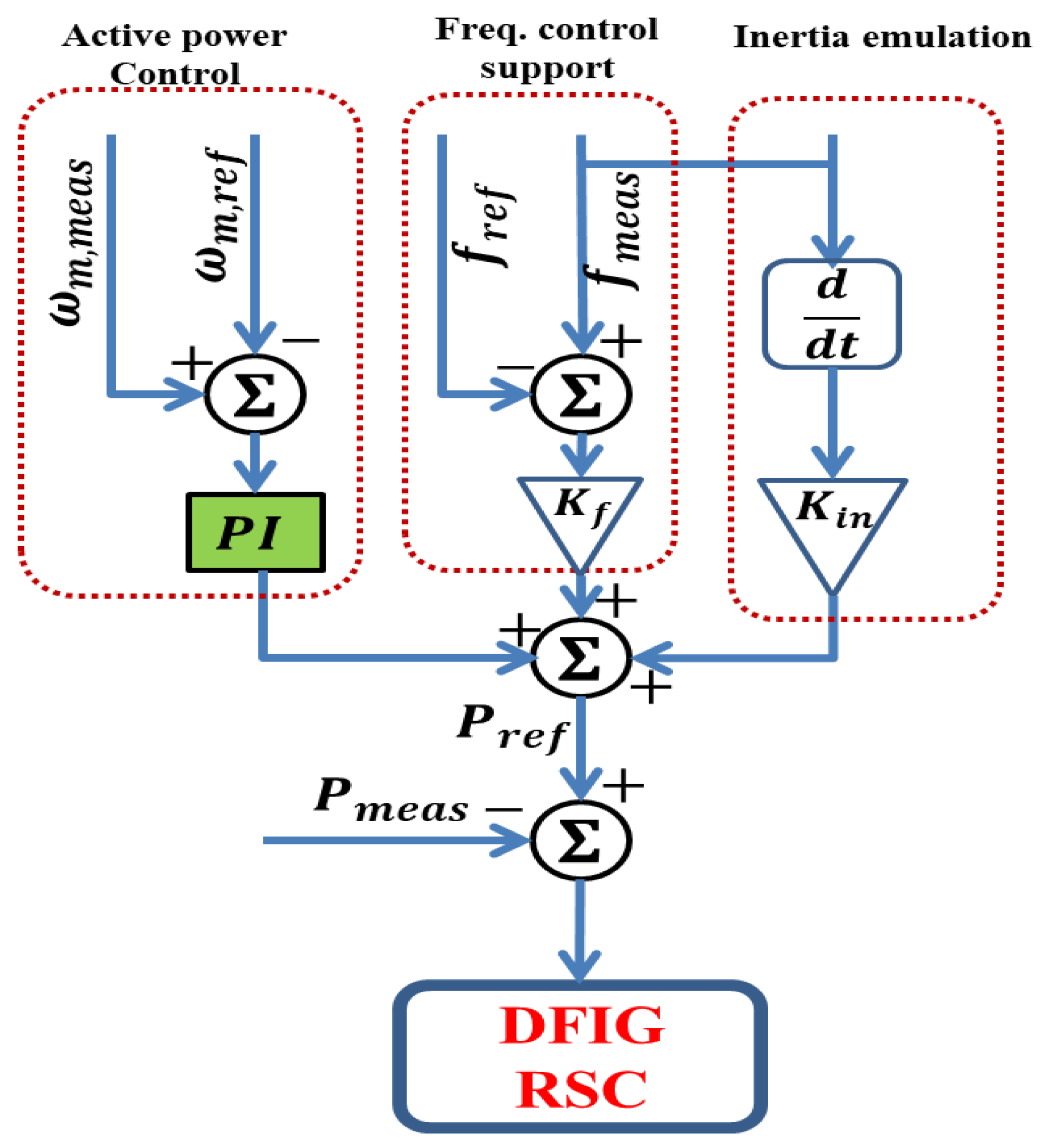
The traditional control method for the rotor-side converter (RSC) in a DFIG system integrates three key functionalities: frequency control support, inertia emulation control, and active power control, as depicted in Figure 2. Frequency control support adjusts the reference active power based on frequency deviation Δ f . The difference between the reference and measured frequencies is multiplied by gain K f to determine the contribution of this control loop. The inertia emulation control mimics the inertial response of a conventional generator. The measured frequency is passed through a derivative block, and the resulting signal is scaled by gain K i n to influence the reference active power. The active power control utilizes a PI controller to regulate reference active power P R e f based on the difference between the reference and measured rotor speeds [32,42].
In steady-state operation, the measured frequency is a constant value, and thus, its derivative equals zero. Also, the difference between the measured and reference frequencies is almost equal to zero. Thus, reference active power P R e f is the output of the PI controller. However, during load variations, the measured frequency is not a constant value, and thus the reference active power, P R e f equal the sum of active power control, frequency control support, and inertia emulation. This allows for swift adjustments in the DFIG’s active power reserve, ultimately contributing to frequency stabilization [32].
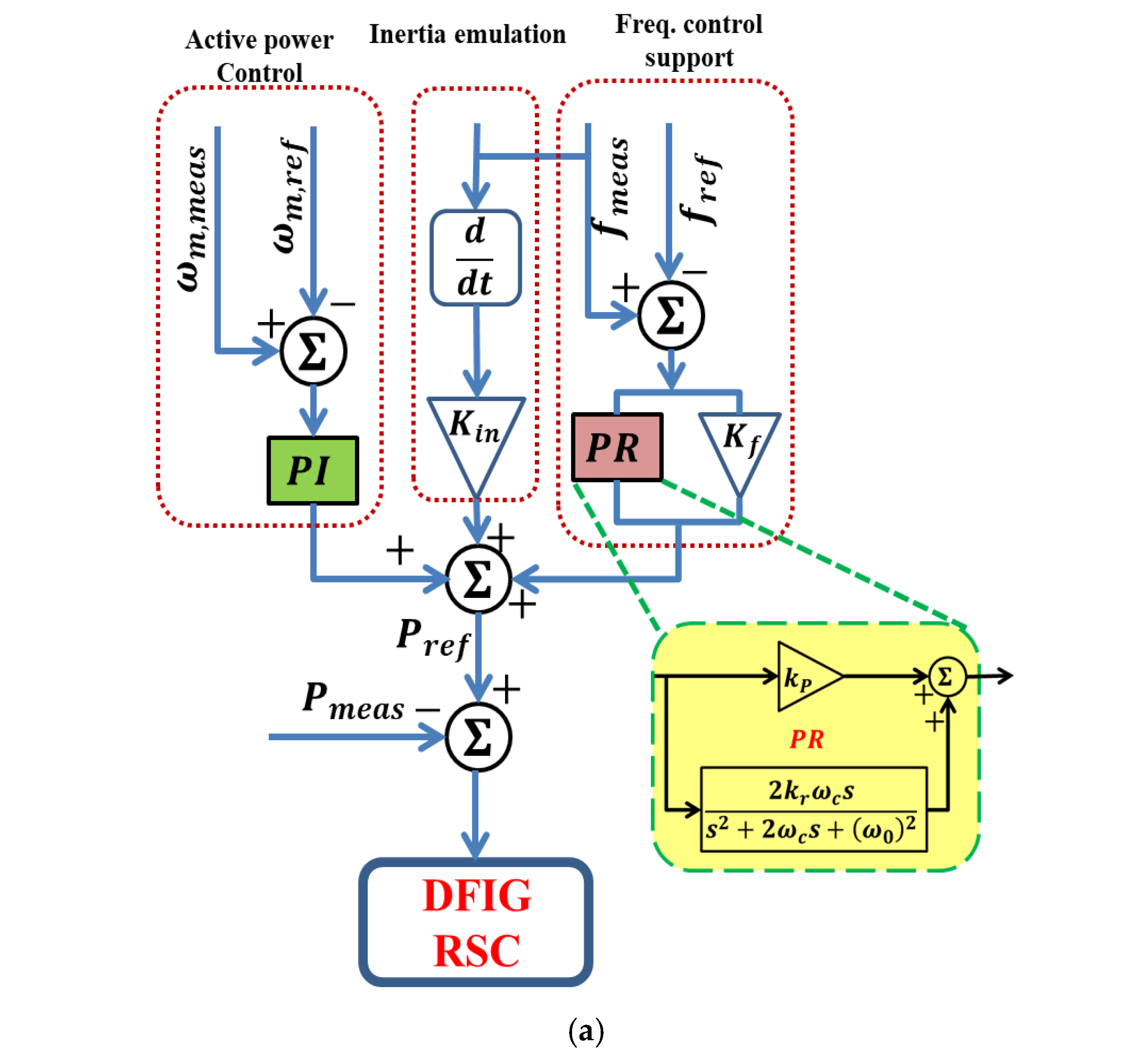
A viable substitute for the PI controller is the PR controller. Its capacity to remove steady-state error by offering more gain at the precise resonance frequency of the regulated signal is one of its main advantages [43]. Furthermore, the PR controller permits the integration of a harmonic compensator while maintaining dynamic control, resulting in excellent current management [44,45]. In addition, using a stationary reference frame instead of the synchronous reference frame “dq” technique simplifies current control. This is because it is no longer necessary for Park’s metamorphosis, which was a source of complexity [46]. Significantly, currents in the stationary frame’s alpha-beta (α-β) coordinates are not cross-coupled, so decoupling circuitry is not required [45]. In order to correct for harmonics in the control signal, the PR control can also operate as a notch filter [47]. As a result, the PR controller was used in a number of applications, including active power filters [48] and voltage source inverters [49]. As per these merits, the authors investigate the application of the PR controller in combination with the inertia emulation effect, as depicted in Figure 3. The following is a mathematical description of the PR controller:
G s = k p + 2 k r ω c s s 2 + 2 ω c s + ω 0 2 ,
where ω c is the quasi-resonant controller’s cut-off frequency, ω o is resonant frequency, and k r , k p represents resonant and proportional factors, respectively.
Such control methodologies are founded on the swing equation of traditional synchronous machines [50]. The power setpoint p e * is determined from the grid frequency ω g , which is approximated by a PLL, as follows:
p e * = d ω g d t 2 H ,
where H denotes the inertia constant. The major disadvantage of this method is that the derivative component is extremely vulnerable to noise in the estimated frequency. Various control strategies have been suggested to address this difficulty, such as employing a first-order low-pass filter at the expected frequency [50]. The p e * can be written as the following considering implementation of the first-order low-pass filter considering the scheme in Figure 2.
p e * ( s ) = 2 H ω n s s + ω n ω g ( s ) + K f ω * ω g ( s ) + p * ,
where p * is an external power setpoint, and ω * is the rated frequency. Gain K f serves as a central regulation. The term k f ω g ( s ) ω * was added as virtual damping against power oscillations in many reported works [51]. Nevertheless, this phrase corresponds to droop control, and its use would alter the power distribution in the steady state established by the grid operator. Consequently, it is unfeasible to enhance the control damping without affecting the power transfer in steady-state conditions with the initial structural constraint of the first order filter-based inertia emulation. One can note that the utilization of the PR controller may solve this issue.
Moreover, the behavior of the virtual damping can also be determined by rewriting Equation (22) as follows:
p e * = 2 H ω n k ω + 2 H ω n ω n s + ω n ω g ( s ) ,
This indicates that the transient has two separate terms: the first is 2 H ω n ω g s , which instructs the converter to generate an almost instantaneous peak in active power in reaction to fluctuations in grid frequency, which is beneficial for inertial response. However, an active power transient in the grid triggers the LC resonance, leading to high-frequency oscillations in the voltages. At its peak amplitude, the subsequent transient is characterized by the classical dynamics of a first-order system, as illustrated in Term 2.
The mathematical formulation for the control scheme in Figure 3 is constructed independently to demonstrate their unique functionalities. The control system consists of two parallel controllers, as well as the active power control. The inertia emulation controller injects virtual inertia into the system by coupling frequency variations with power output, while the PR controller compensates for frequency deviations by amplifying errors at the fundamental frequency. Moreover, both controllers contribute to the power reference signal applied to the RSC, which adjusts the DFIG response. As reported, the speed controller alone cannot emulate inertia during power imbalances because the rotor speed is decoupled from the grid frequency. So, the control scheme functions as a supplementary controller, establishing a dynamic relationship between rotor speed and grid frequency. The inertia power can be further expressed as:
P e t = ) = 2 H ω n s s + ω n ω g s I n e r t i a   E m u l a t i o n k p + K f + 2 k r ω c s s 2 + 2 ω c s + ω 0 2 ω * ω g ( s ) F r e q u e n c y   c o n t r o l   s u p o o r t + p *
where Δ ω t = ω * ω g ( s ) , and ω g is the frequency at the converter terminals which is estimated by the PLL. It should note that 2 H = k i n .
The transfer function G s = P e * s ω g s is:
G s = 2 H ω n s s + ω n + k p + K f + 2 k r ω c s s 2 + 2 ω c s + ω 0 2
The estimated natural frequency ω n and damping ratio ζ can be calculated based the key second-order term which has a denominator of s 2 + 2 ω c s + ω 0 2 , neglecting the first order filter. When comparing with the standard second-order system, ω n and ζ can be calculated as:
ω n = ω 0 , ζ = ω c ω 0
In such a case, to ensure the system remains proper and causal considering the first order filter with the inertia emulation, the characteristic equation can be written as:
s 2 + 2 ω c s + ω 0 2 + 2 H ω n s s + ω n k p + K f = 0
We approximated ω n s s + ω n using a low-frequency approximation as ω n s s + ω n ω n s ω n = s for low frequencies s ω n . The characteristic equation can be rewritten as:
s 2 + 2 ω c + 2 H s + ω 0 2 k p + K f = 0
ω n and ζ can be estimatted as:
ω n = ω 0 2 k p + K f
ζ = 2 ω c + 2 H 2 ω n
Moreover, including the first order filter with the based inertia emulation has been considered. So, the stability of virtual swing equation considering the first term of the inertia emulation denominator based the characteristic polynomial 2 H X s s 2 + X s k d s + ω b can be determined as the natural frequency is ω n = ω b 2 H X s and the damping ratio is ζ = k d 2 2 H ω b X s . To achieve a non-oscillatory response, the k i n > 8 H ω b X s should be determined.
For frequency support control, the proportional gain k p + K f may enhance the steady-state error correction and for transient response improvement. Moreover, the resonant term 2 k r ω c s s 2 + 2 ω c s + ω 0 2 may assist in the harmonic rejection. In this case, the system will be stable when ( ω c < ω 0 ) (resonant frequency below Nyquist limit), but the gain limitation of ( k r < ω 0 2 2 ω c ) should be considered.
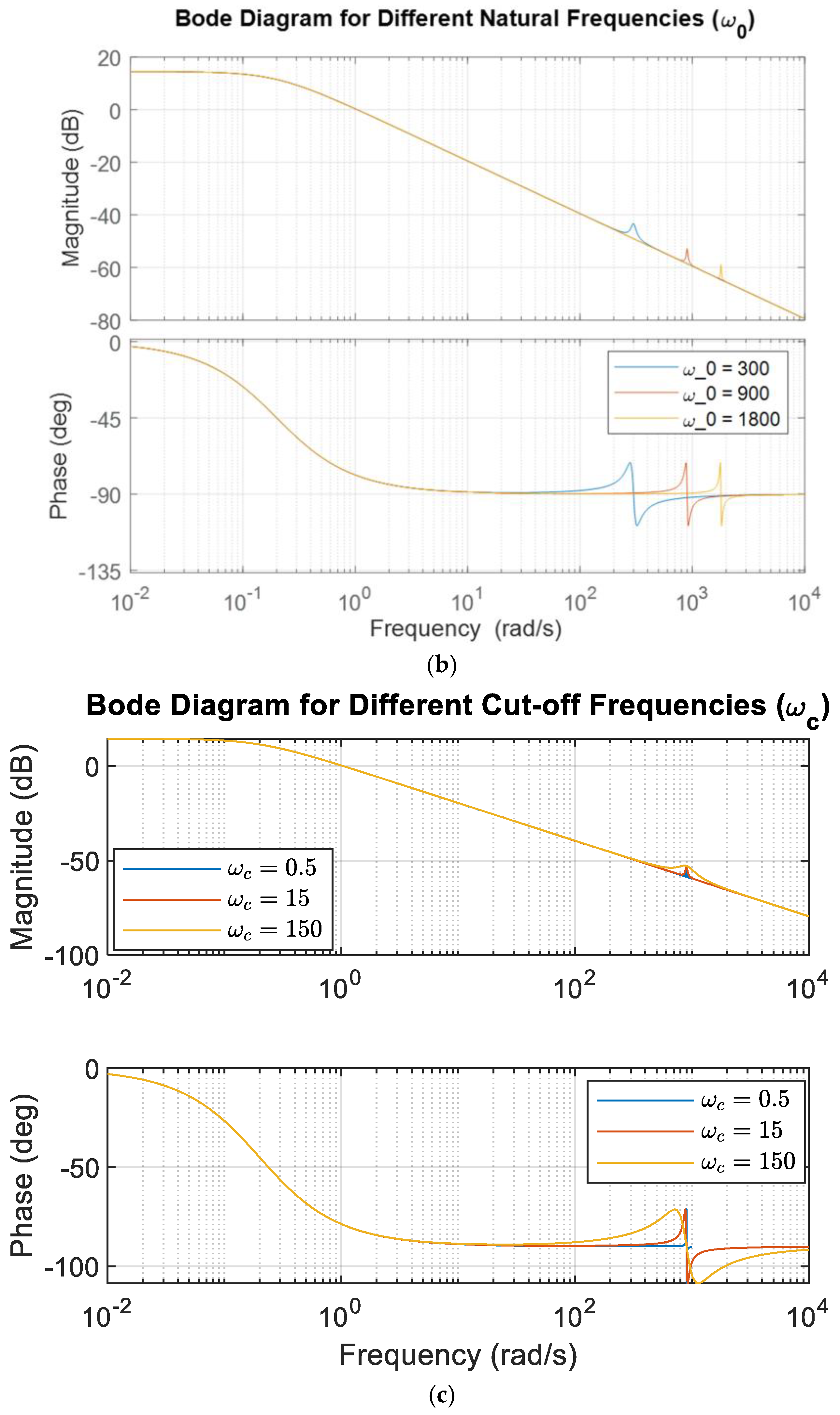
As considered in the simulation results, the tuning parameters were determined by trial and error and considering the previous analysis. We started with ( K d ) adjustment for damping performance enhancement, then ( K f ) was adjusted for transient response. Finally, we tuned ( k p ) , and ( k r ) to achieve steady-state performance. Figure 3b shows a bode diagram with various values of ω o , while Figure 3c illustrates the bode diagram with various values of ω c . The results prove the system stability with excellent dynamic performance.
In what follows, the impact of the PR controller’s parameters on frequency regulation will be studied to select the optimum values that achieve the lowest frequency deviation while maintaining system stability.

3.1. Impact of the PR Controller’s Cut-Off Frequency

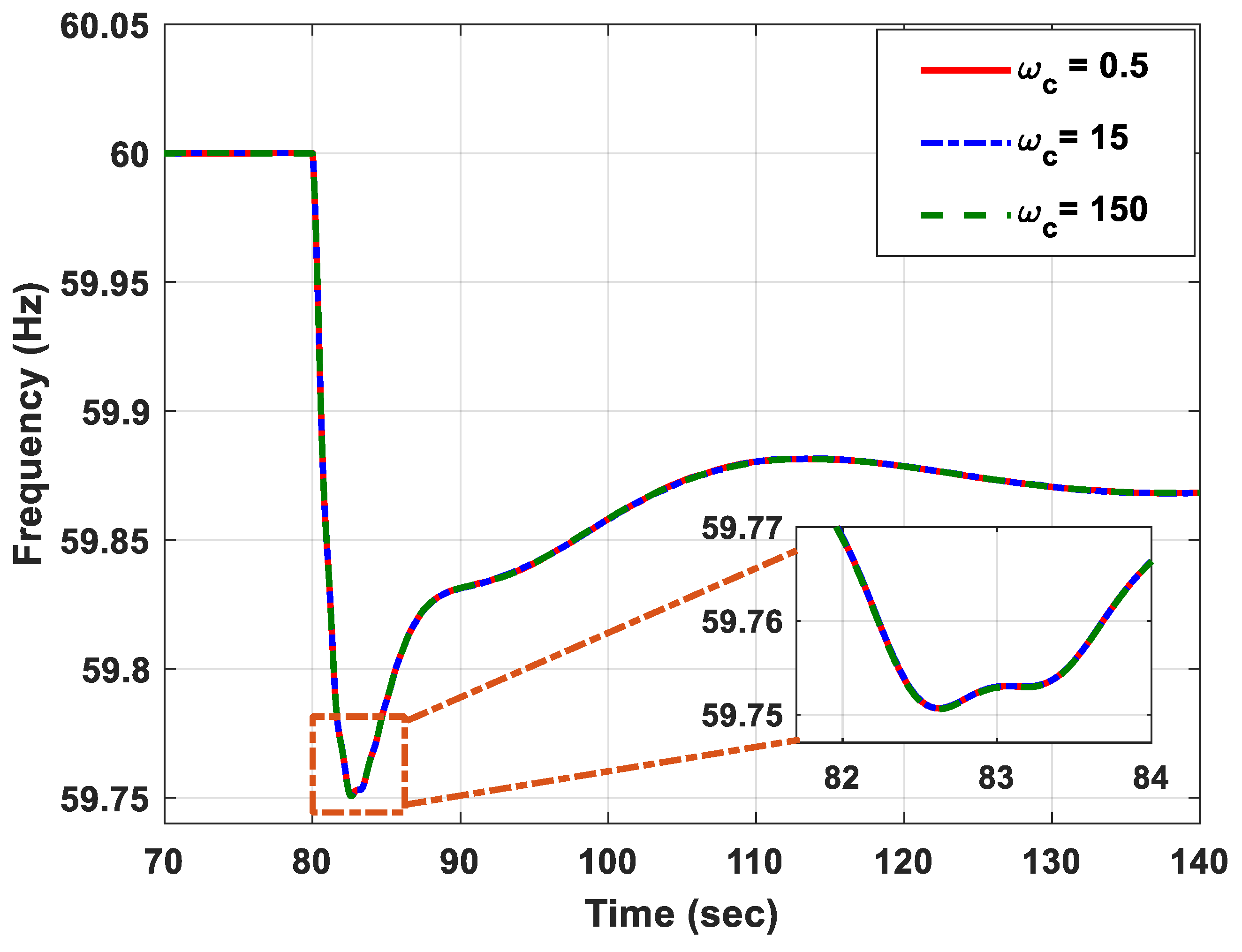
In this case, the K r , ω o , and K p were set at 10,900 and 0.6, respectively. The simulation was carried out within a wide range of cut-off frequencies (0.5 to 150 rad/s), as shown in Figure 4. It can be observed that changing the cut-off frequency did not affect the frequency response, where the same lowest frequency drops (59.75 Hz) were obtained when the cut-off frequency equaled 0.5, 15, 150 rad/s.

3.2. Impact of the PR Controller’s Resonant Factor

In this study, the ω c , ω o , and K p equals 15,900 and 0.6, respectively. The simulation was conducted with three different values of K r , namely, 0.2, 10, and 120, as illustrated in Figure 5. No effect of the resonant factor on the frequency response was observed when the load was increased at t = 80   s , where the system frequency had the same track with varying the resonant factor’s value.

3.3. Impact of the PR Controller’s Resonant Frequency

In this study, the ω c , K r , and K p equaled 15 ,   10 ,   a n d   0.6 , respectively. The system frequency response is plotted when ω o was equal to 300, 900, and 1800, as depicted in Figure 6. It is obvious that the obtained results are consistent at the different values of the resonant frequency.

3.4. Impact of the PR Controller’s Proportional Gain

In this scenario, ω c , ω o , and K r equal 15,900 and 10, respectively. The simulation was performed with different values of K p , i.e., from 0.1 to 8.0. As shown in Figure 7 and Table 1, within a specific range (0.1 to 1.5), it can be noted that the higher the proportional gain, the lower (higher) the frequency deviation (overshoot), and the longer the settling time. It should be noted that the frequency deviation was equal to 60. For example, when the K p was equal to 0.1 and 0.5, the frequency drop was equal to 59.705 and 59.742 Hz, the frequency deviation was equal to 0.295 and 0.258, and the overshoot equaled 59.876 and 59.88 Hz. That is to say, the frequency deviation is inversely proportional to the overshoot or settling time. On the other hand, when K p was increased from 2.0 to 4.0, both the frequency deviation, overshoot, and the required time to reach a steady state increased. However, the system became unstable when K p = 8.0. This means that the value of K p must be in a range between 0.1 and 2.0. Based on the simulation results, the proportional gain was set at 0.9 in this study as a compromise between the frequency deviation and overshoot.

4. Results and Discussion

The power system model described in Section 2 was built in MATLAB/Simulink (2023b) software in order to analyze the proposed method’s performance to enhance the system frequency with a varying load. The system performance in terms of the frequency (Hz), rate of change of frequency ROCOF (Hz/s), and DFIG active power (MW) were extracted from the model without a controller, with the traditional method [32] and the proposed method in three different scenarios, namely, decreasing load, increasing load, and multi-step load perturbation. In this study, the PR controller’s proportional gain, resonant frequency, resonant factor, and cut-off frequency were set at 0.9, 900, 10, and 15, respectively.

4.1. Impact of Increasing the Load

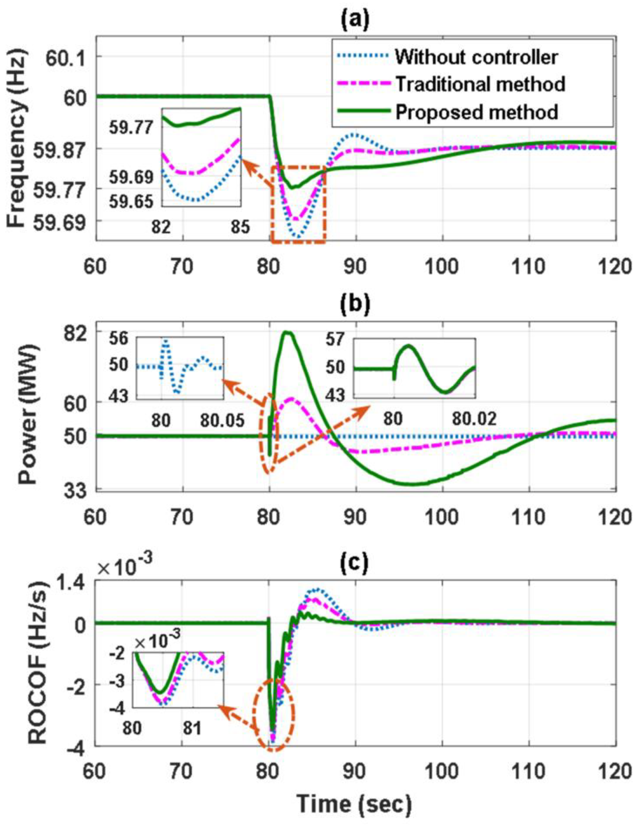
At first, the two loads, L 1   and   L 2 , were linked to the system, where the two circuit breakers, C . B 1 and C . B 2 , were closed, as shown in Figure 1. Then, the third circuit breaker, C . B 3 , was used to connect an additional load, L 3 , to the system when t = 80   s , as shown in Figure 8. The obtained frequency response, Figure 8a, shows that the frequency drop (frequency deviation) was equal to 59.65 Hz (60 − 59.65 = 0.35), 59.69 Hz (0.31), and 59.77 Hz (0.23) without a controller, with the traditional method, and the proposed method, respectively. Also, Figure 8b shows that DFIG active power reached 56 MW, 60 MW, and 82 MW when the load was increased without a controller, with the traditional method and the proposed method, respectively. That is to say, the reserved power was equal to (56 − 50 = 6 MW), (60 − 50 = 10 MW) and (82 − 50 = 32 MW). Based on these results, it is obvious that the lowest frequency deviation and ROCOF and the higher reserved power were accomplished by the proposed method compared to the traditional method.

4.2. Impact of Reducing the Load

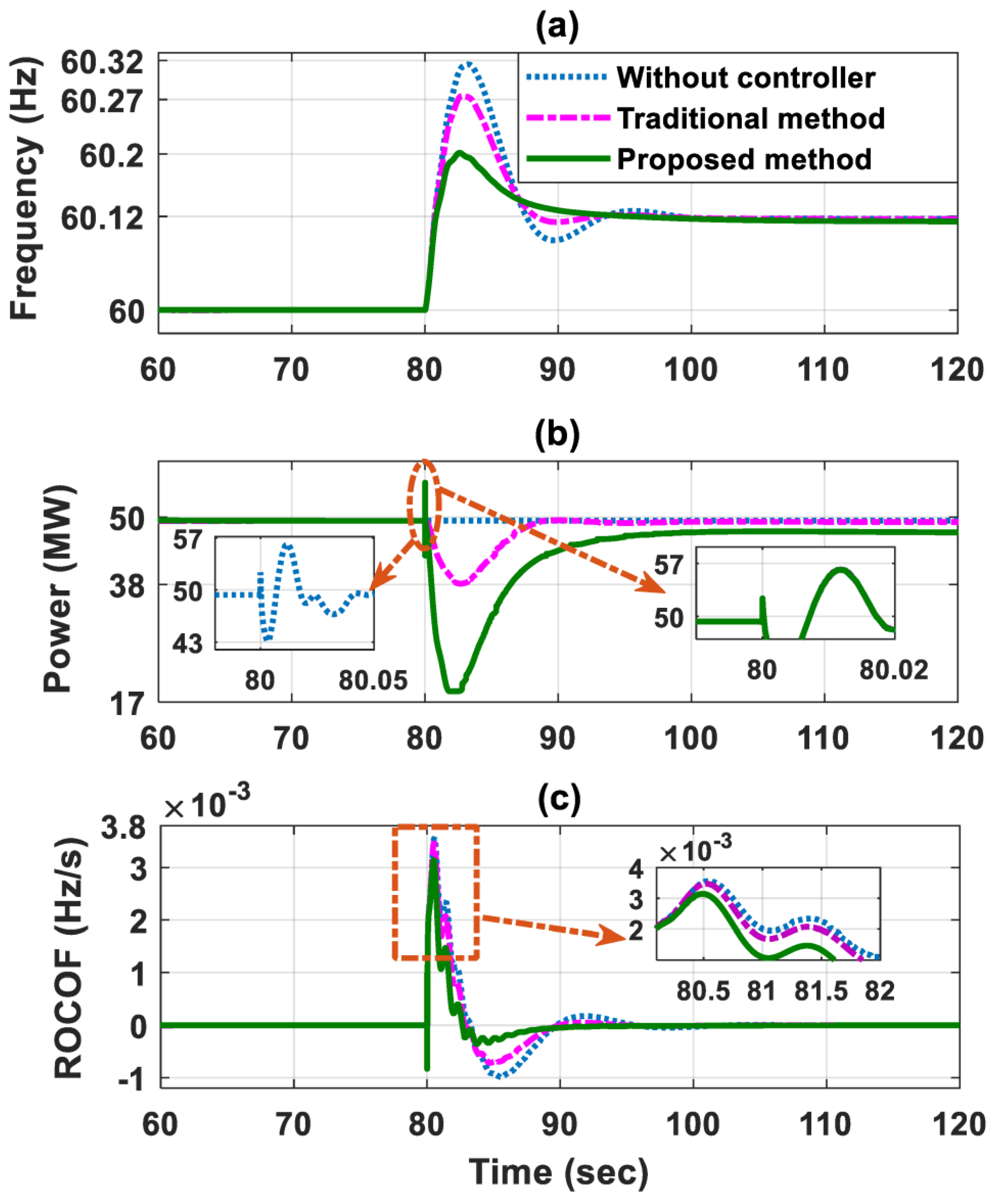
Initially, L 1   and   L 2 , were linked to the system by C . B 1 and C . B 2 , respectively. Then, C . B 2 was opened when t = 80   s , and thus L 2 went out of service, as shown in Figure 9. Thus, the frequency increased as given in Figure 9a, where the overshoot was equivalent to 60.2 Hz, 60.27 Hz, and 60.32 Hz with the presented method, traditional method, and without a controller, respectively. Consequently, the frequency deviation equaled 0.2, 0.27, and 0.32, respectively. On the other hand, the reserved power provided by the presented method, the traditional method, and when the controller off was equal to 32 MW, 12 MW, and 7 MW, respectively. Moreover, in Figure 9c, the lowest overshoot and undershoot were achieved by the proposed method. These outcomes show that the more reserved power and the lowest frequency deviation were achieved by the proposed method.

4.3. Impact of Multi-Step Load Perturbation

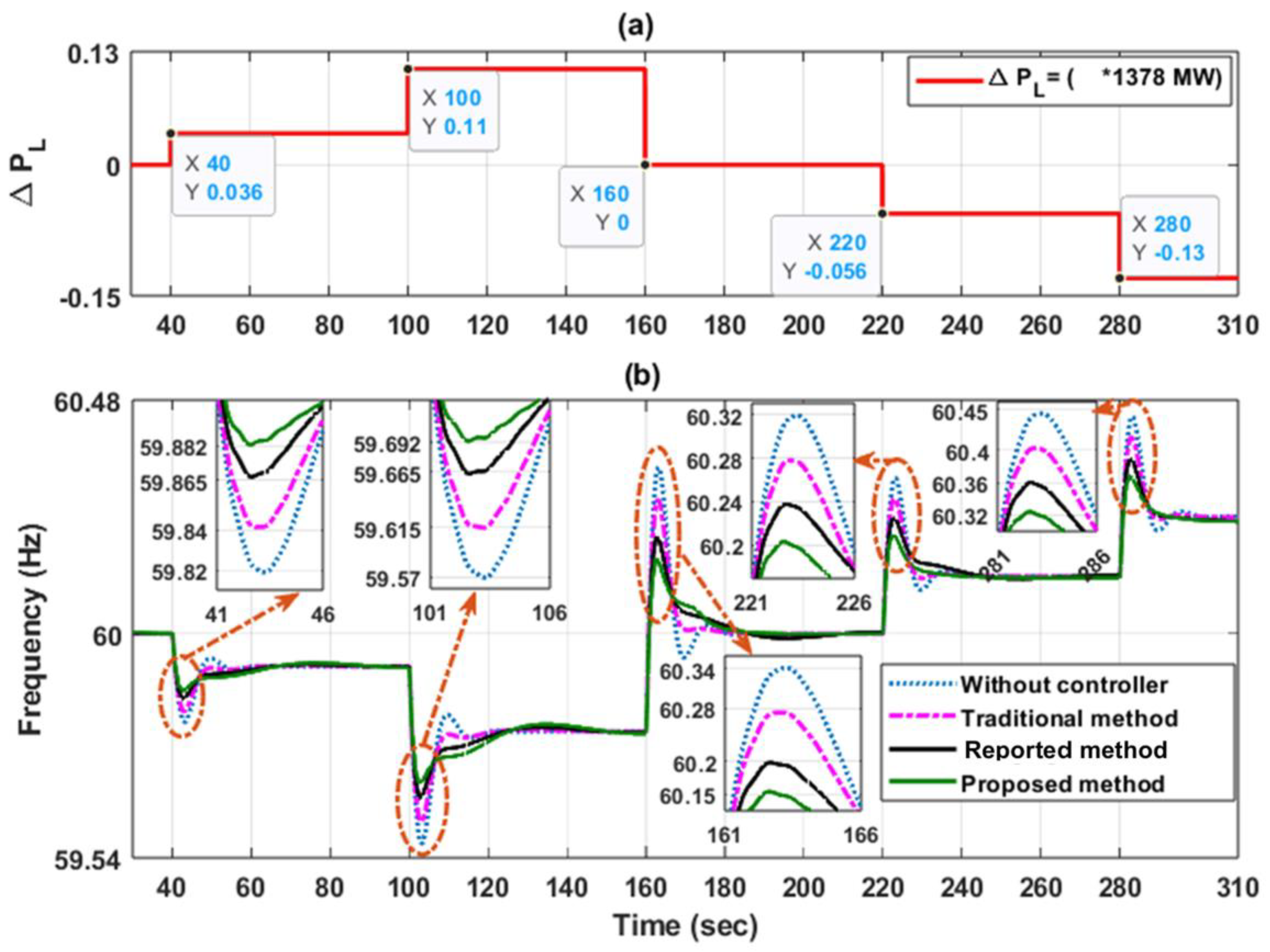
In order to ensure the effectiveness and ability of the proposed method to improve the system frequency, it was tested with a series load disturbance ranging from 11% to −13% of the initial load. Moreover, the presented method’s performance was compared to the traditional method as well as one of the previous methods [31], as shown in Figure 10. It should be noted that in [31], a washout filter was added to the inertial controller. The percentage of a series load, P L , was equal to 3.6%, 11%, zero, −5.6%, and −13% of the initial load when t = 40   s , 100   s , 160   s , 220   s , and 280   s , as shown in Figure 10a. The obtained frequency response shows that the lowest frequency deviation at different loads was achieved with the proposed method. For example, when P L = 11 % of the initial load, the frequency drop (frequency deviation) was equal to 59.692 Hz (60 − 59.692 = 0.308), 59.665 Hz (0.335), 59.615 Hz (0.385), and 59.57 Hz (0.43) with the proposed method, the previous method [31], the traditional method [32], and without a controller, respectively. These results demonstrate that the best performance was accomplished by the proposed method. Also, it is clear that the selected values for the PR controllers (Section 3) can effectively improve the system frequency at different loads, as shown in Figure 10.

5. Conclusions

In this paper, the ability of a combined inertial controller and proportional resonant (PR) controller to support the system frequency in a DFIG was investigated. This study involved determining the optimum values of the PR controller parameters to minimize frequency deviation and overshoot. Furthermore, the proposed method’s performance was examined at different load perturbations and compared to the traditional method and one of the previous methods. The simulation outcomes prove that: (1) No effect was observed on the frequency response with a changing resonant factor, resonant frequency, or cut-off frequency of the PR controller; (2) varying the proportional gain of the PR controller greatly affected the frequency deviation, overshoot, and system stability; (3) the most reserve power and the lowest frequency deviation were accomplished by the proposed method at different loads; and (4) the presented approach provided fast frequency support in every scenario examined. The performance of an adaptive PR controller for system frequency regulation could be the subject of future work. Moreover, future research will focus on the application of intelligent optimization algorithms to determine the optimal values of the control parameters. Additionally, parametric studies will be expanded to evaluate the robustness of the controller under various system conditions and perturbations.

Author Contributions

Conceptualization, M.A., M.A.E.-D., M.K.A. and A.A.Z.D.; Data curation, S.A.D., A.A.Z.D. and A.G.A.E.-M.; Formal analysis, M.A.E.-D., M.K.A. and E.T.; Investigation, E.T. and A.A.Z.D.; Methodology, M.A., M.A.E.-D., M.K.A., E.T., A.A.Z.D. and A.G.A.E.-M.; Resources, M.A.E.-D. and E.T.; Software, M.A., M.A.E.-D. and A.A.Z.D.; Validation, M.A., M.A.E.-D., M.K.A., A.A.Z.D. and A.G.A.E.-M.; Visualization, S.A.D. and A.A.Z.D.; Writing—original draft, M.A., S.A.D., M.A.E.-D., M.K.A., E.T., A.A.Z.D. and A.G.A.E.-M.; Writing—review and editing, M.A., S.A.D., M.A.E.-D., A.A.Z.D. and A.G.A.E.-M. All authors have read and agreed to the published version of the manuscript.

Funding

This research received no external funding.

Data Availability Statement

The original contributions presented in this study are included in the article.

Acknowledgments

The authors extend their appreciation to the Northern Border University, Saudi Arabia for supporting this work through project number “NBU-CRP-2025-2448’’.

Conflicts of Interest

The authors declare no conflicts of interest.

Appendix A

Table A1. DFIG parameters.
Rated power1.5 MW
Number of wind turbines 100
Rated voltage575 V
Rated frequency60 Hz
R s 0.007 p.u.
R r 0.005 p.u.
X l s 0.171 p.u.
X l r 0.156 p.u.
X m 2.9 p.u.
DC-link voltage1200 V
DC-bus capacitor 10,000 μF × 100
Table A2. Synchronous generator parameters.
Rated power675 MW
Rated voltage 20 kV
Rated frequency60 Hz
Armature resistance0.0025 p.u.
Pole pairs 4
Inertia coefficient6.5 s
Unsaturated   reactance   X d 1.8 p.u.
Unsaturated   transient   reactance   X d 0.3 p.u.
Unsaturated   transient   time   constant   ( open )   T d 0 8 s
Unsaturated   sub - transient   reactance   X d 0.25 p.u.
Unsaturated   sub - transient   time   constant   ( open )   T d 0 0.03 s
Unsaturated   reactance   X q 1.7 p.u.
Unsaturated   transient   reactance   X q 0.55 p.u.
Unsaturated   transient   time   constant   ( open )   T q 0 0.4 s
Unsaturated   sub - transient   reactance   X q 0.25 p.u.
Unsaturated   sub - transient   time   constant   ( open )   T q 0 0.05 s

References

  1. Xue, Y.; Tai, N. Review of contribution to frequency control through variable speed wind turbine. Renew. Energy 2011, 36, 1671–1677. [Google Scholar] [CrossRef]
  2. Makolo, P.; Zamora, R.; Lie, T.-T. The role of inertia for grid flexibility under high penetration of variable renewables-A review of challenges and solutions. Renew. Sustain. Energy Rev. 2021, 147, 111223. [Google Scholar] [CrossRef]
  3. Ochoa, D.; Martinez, S. Fast-frequency response provided by DFIG-wind turbines and its impact on the grid. IEEE Trans. Power Syst. 2016, 32, 4002–4011. [Google Scholar] [CrossRef]
  4. Ma, C.; Sun, J.; Huang, J.; Wang, K. Transient Stability Enhancement Strategy for Islanded Microgrids Based on Energy Storage–Virtual Synchronous Machine Control. Energies 2023, 16, 6390. [Google Scholar] [CrossRef]
  5. Xu, Y.; Wang, H.; Yang, D. An enhanced frequency response strategy of a DFIG based on over-speed de-loaded curve. Appl. Sci. 2021, 11, 9324. [Google Scholar] [CrossRef]
  6. Prasad, R.; Padhy, N.P. Synergistic frequency regulation control mechanism for DFIG wind turbines with optimal pitch dynamics. IEEE Trans. Power Syst. 2020, 35, 3181–3191. [Google Scholar] [CrossRef]
  7. Hu, Y.-L.; Wu, Y.-K. Approximation to frequency control capability of a DFIG-based wind farm using a simple linear gain droop control. IEEE Trans. Ind. Appl. 2018, 55, 2300–2309. Available online: http://ieeexplore.ieee.org/document/8579184/ (accessed on 10 March 2025). [CrossRef]
  8. Attya, A.B.; Hartkopf, T. Wind turbines support techniques during frequency drops—Energy utilization comparison. AIMS Energy 2014, 2, 260–275. [Google Scholar] [CrossRef]
  9. Attya, A.; Dominguez-Garcia, J.L.; Anaya-Lara, O. A review on frequency support provision by wind power plants: Current and future challenges. Renew. Sustain. Energy Rev. 2018, 81, 2071–2087. [Google Scholar] [CrossRef]
  10. Sun, M.; Sun, Y.; Chen, L.; Zou, Z.; Min, Y.; Liu, R.; Xu, F.; Wu, Y. Novel temporary frequency support control strategy of wind turbine generator considering coordination with synchronous generator. IEEE Trans. Sustain. Energy 2022, 13, 1011–1020. [Google Scholar] [CrossRef]
  11. Liu, Y.; Zhang, B.; Zhang, Y. Electronically controlled broadband terahertz amplitude modulator based on Ionic Liquid/PEDOT: PSS: DMSO composite structure. J. Opt. Photonics Res. 2024. [Google Scholar] [CrossRef]
  12. Khaki-Sedigh, A.; Nasrollahi, S. A review of data-driven control systems design: Concepts and methods. J. Control 2023, 17, 81–111. Available online: http://joc.kntu.ac.ir/article-1-1007-en.html (accessed on 10 March 2025). [CrossRef]
  13. Nematov, D. Analysis of the optical properties and electronic structure of semiconductors of the Cu2NiXS4 (X = Si, Ge, Sn) family as new promising materials for optoelectronic devices. J. Opt. Photonics Res. 2024, 1, 91–97. [Google Scholar] [CrossRef]
  14. Alam, M.K.; Afsary, N.; Islam, M.Z.; Rasel, M.O.F. Investigation of polymer-based 1× 2 all-optical switches at C-band wavelength. J. Opt. Photonics Res. 2024, 1, 59–66. [Google Scholar] [CrossRef]
  15. Hu, Z.; Ren, Y.; Meng, Q.; Yun, P.; Fang, C.; Pan, Y. Improvement of frequency support for a DFIG using a virtual synchronous generator strategy at large power angles. Energies 2023, 16, 914. [Google Scholar] [CrossRef]
  16. Wang, S.; Tomsovic, K. A novel active power control framework for wind turbine generators to improve frequency response. IEEE Trans. Power Syst. 2018, 33, 6579–6589. [Google Scholar] [CrossRef]
  17. Li, Y.; He, L.; Liu, F.; Tan, Y.; Cao, Y.; Luo, L.; Shahidehpour, M. A dynamic coordinated control strategy of WTG-ES combined system for short-term frequency support. Renew. Energy 2018, 119, 1–11. [Google Scholar] [CrossRef]
  18. Zhao, S.; Zhang, T.; Ma, S.; Chen, M. Dandelion Optimizer: A nature-inspired metaheuristic algorithm for engineering applications. Eng. Appl. Artif. Intell. 2022, 114, 105075. [Google Scholar] [CrossRef]
  19. Zhu, J.; Hu, J.; Hung, W.; Wang, C.; Zhang, X.; Bu, S.; Li, Q.; Urdal, H.; Booth, C.D. Synthetic inertia control strategy for doubly fed induction generator wind turbine generators using lithium-ion supercapacitors. IEEE Trans. Energy Convers. 2017, 33, 773–783. [Google Scholar] [CrossRef]
  20. Cui, S.; Yan, X.; Siddique, A. Inertia and primary frequency modulation strategy for a doubly fed induction generator based on supercapacitor energy storage control. Int. J. Green Energy 2022, 19, 941–955. [Google Scholar] [CrossRef]
  21. Sun, D.; Yu, J.; Zheng, W.; Ruan, J.; Zu, G. Multi-energy cooperative primary frequency regulation analysis of a hybrid plant station for wind power and hydrogen production based on ensemble empirical-mode decomposition algorithm. Appl. Sci. 2023, 13, 12394. [Google Scholar] [CrossRef]
  22. Sun, D.; Long, H.; Zhou, K.; Lv, Y.; Zheng, J.; Chen, Q. Research on SCESS-DFIG DC bus voltage fluctuation suppression strategy for frequency inertia regulation of power grid. IEEE Access 2020, 8, 173933–173948. [Google Scholar] [CrossRef]
  23. Okedu, K.E. A variable speed wind turbine flywheel based coordinated control system for enhancing grid frequency dynamics. Int. J. Smart Grid 2018, 2, 123–134. [Google Scholar] [CrossRef]
  24. Díaz-González, F.; Hau, M.; Sumper, A.; Gomis-Bellmunt, O. Coordinated operation of wind turbines and flywheel storage for primary frequency control support. Int. J. Electr. Power Energy Syst. 2015, 68, 313–326. [Google Scholar] [CrossRef]
  25. Kerdphol, T.; Rahman, F.S.; Mitani, Y. Virtual inertia control application to enhance frequency stability of interconnected power systems with high renewable energy penetration. Energies 2018, 11, 981. [Google Scholar] [CrossRef]
  26. Guggilam, S.S.; Zhao, C.; Dall’Anese, E.; Chen, Y.C.; Dhople, S.V. Optimizing power–frequency droop characteristics of distributed energy resources. IEEE Trans. Power Syst. 2017, 33, 3076–3086. [Google Scholar] [CrossRef]
  27. Tian, X.; Wang, W.; Chi, Y.; Li, Y.; Liu, C. Virtual inertia optimisation control of DFIG and assessment of equivalent inertia time constant of power grid. IET Renew. Power Gener. 2018, 12, 1733–1740. [Google Scholar] [CrossRef]
  28. Zhou, Y.; Hu, J.; He, W. Synchronization mechanism between power-synchronized VS and PLL-controlled CS and the resulting oscillations. IEEE Trans. Power Syst. 2022, 37, 4129–4132. [Google Scholar] [CrossRef]
  29. Zhang, X.; Hu, Y.; Mao, W.; Zhao, T.; Wang, M.; Liu, F.; Cao, R. A grid-supporting strategy for cascaded H-bridge PV converter using VSG algorithm with modular active power reserve. IEEE Trans. Ind. Electron. 2020, 68, 186–197. [Google Scholar] [CrossRef]
  30. Deng, J.; Wang, J.; Li, S.; Zhang, H.; Peng, S.; Wang, T. Adaptive damping design of PMSG integrated power system with virtual synchronous generator control. Energies 2020, 13, 2037. [Google Scholar] [CrossRef]
  31. Abdeen, M.; Sayyed, M.; Domínguez-García, J.L.; Kamel, S. Supplemental control for system frequency support of DFIG-based wind turbines. IEEE Access 2022, 10, 69364–69372. [Google Scholar] [CrossRef]
  32. Morren, J.; De Haan, S.W.; Kling, W.L.; Ferreira, J. Wind turbines emulating inertia and supporting primary frequency control. IEEE Trans. Power Syst. 2006, 21, 433–434. [Google Scholar] [CrossRef]
  33. Liu, J.; Yang, Z.; Yu, J.; Huang, J.; Li, W. Coordinated control parameter setting of DFIG wind farms with virtual inertia control. Int. J. Electr. Power Energy Syst. 2020, 122, 106167. [Google Scholar] [CrossRef]
  34. Kazemi, M.V.; Sadati, S.J.; Gholamian, S.A. Adaptive frequency control support of a DFIG based on second-order derivative controller using data-driven method. Int. Trans. Electr. Energy Syst. 2020, 30, e12424. [Google Scholar] [CrossRef]
  35. Liu, Y.; Jiang, L.; Smith, J.S.; Wu, Q. Primary frequency control of DFIG-WTs using bang-bang phase angle controller. IET Gener. Transm. Distrib. 2018, 12, 2670–2678. [Google Scholar] [CrossRef]
  36. Ouyang, J.; Pang, M.; Li, M.; Zheng, D.; Tang, T.; Wang, W. Frequency control method based on the dynamic deloading of DFIGs for power systems with high-proportion wind energy. Int. J. Electr. Power Energy Syst. 2021, 128, 106764. [Google Scholar] [CrossRef]
  37. Kerdphol, T.; Rahman, F.S.; Watanabe, M.; Mitani, Y. Synthesis of Robust Virtual Inertia Control. In Power Systems; Springer International Publishing: Berlin/Heidelberg, Germany, 2020; pp. 203–226. [Google Scholar]
  38. Cheng, P.; Wu, C.; Ma, J.; Blaabjerg, F. Coordinated derived current control of DFIG’s RSC and GSC without PLL under unbalanced grid voltage conditions. IEEE Access 2020, 8, 64760–64769. [Google Scholar] [CrossRef]
  39. Hamon, C.; Elkington, K.; Ghandhari, M. Doubly-fed induction generator modeling and control in DigSilent PowerFactory. In Proceedings of the 2010 International Conference on Power System Technology, Zhejiang, China, 24–28 October 2010; pp. 1–7. [Google Scholar]
  40. Li, H.; Abdeen, M.; Chai, Z.; Kamel, S.; Xie, X.; Hu, Y.; Wang, K. An improved fast detection method on subsynchronous resonance in a wind power system with a series compensated transmission line. IEEE Access 2019, 7, 61512–61522. [Google Scholar] [CrossRef]
  41. Abad, G.; Lopez, J.; Rodriguez, M.; Marroyo, L.; Iwanski, G. Doubly Fed Induction Machine: Modeling and Control for Wind Energy Generation; John Wiley & Sons: Hoboken, NJ, USA, 2011. [Google Scholar]
  42. Chen, R.; Wu, W.; Sun, H.; Hu, Y.; Zhang, B. Supplemental control for enhancing primary frequency response of DFIG-based wind farm considering security of wind turbines. In Proceedings of the 2014 IEEE PES General Meeting| Conference & Exposition, National Harbor, MD, USA, 27–31 July 2014; pp. 1–5. [Google Scholar] [CrossRef]
  43. Castilla, M.; Miret, J.; Matas, J.; de Vicuña, L.G.; Guerrero, J.M. Linear current control scheme with series resonant harmonic compensator for single-phase grid-connected photovoltaic inverters. IEEE Trans. Ind. Electron. 2008, 55, 2724–2733. [Google Scholar] [CrossRef]
  44. Liserre, M.; Teodorescu, R.; Blaabjerg, F. Multiple harmonics control for three-phase grid converter systems with the use of PI-RES current controller in a rotating frame. IEEE Trans. Power Electron. 2006, 21, 836–841. [Google Scholar] [CrossRef]
  45. Teodorescu, R.; Blaabjerg, F.; Liserre, M.; Loh, P.C. Proportional-resonant controllers and filters for grid-connected voltage-source converters. IEE Proc. -Electr. Power Appl. 2006, 153, 750–762. [Google Scholar] [CrossRef]
  46. Lee, R.; Pillay, P.; Harley, R. Q reference frames for the simulation of induction motors. Electr. Power Syst. Res. 1984, 8, 15–26. [Google Scholar] [CrossRef]
  47. Teodorescu, R.; Blaabjerg, F. Flexible control of small wind turbines with grid failure detection operating in stand-alone and grid-connected mode. IEEE Trans. Power Electron. 2004, 19, 1323–1332. [Google Scholar] [CrossRef]
  48. Amini, B.; Rastegar, H.; Pichan, M. An optimized proportional resonant current controller based genetic algorithm for enhancing shunt active power filter performance. Int. J. Electr. Power Energy Syst. 2024, 156, 109738. [Google Scholar] [CrossRef]
  49. Haro-Larrode, M.; Santos-Mugica, M.; Eguia, P.; Rodriguez-Sanchez, R.; Gil-de-Muro, A. Impact of proportional resonant controller parameters of VSC connected to AC grids with variable X/R characteristic on the small signal stability. Int. J. Electr. Power Energy Syst. 2020, 118, 105746. [Google Scholar] [CrossRef]
  50. Aragon, D.A.; Unamuno, E.; de Muro, A.G.; Ceballos, S.; Barrena, J.A. Second-Order Filter-Based Inertia Emulation (SOFIE) for Low Inertia Power Systems. IEEE Trans. Power Deliv. 2024, 39, 530–541. [Google Scholar] [CrossRef]
  51. Alam, M.S.; Al-Ismail, F.S.; Salem, A.; Abido, M.A. High-Level Penetration of Renewable Energy Sources Into Grid Utility: Challenges and Solutions. IEEE Access 2020, 8, 190277–190299. [Google Scholar] [CrossRef]
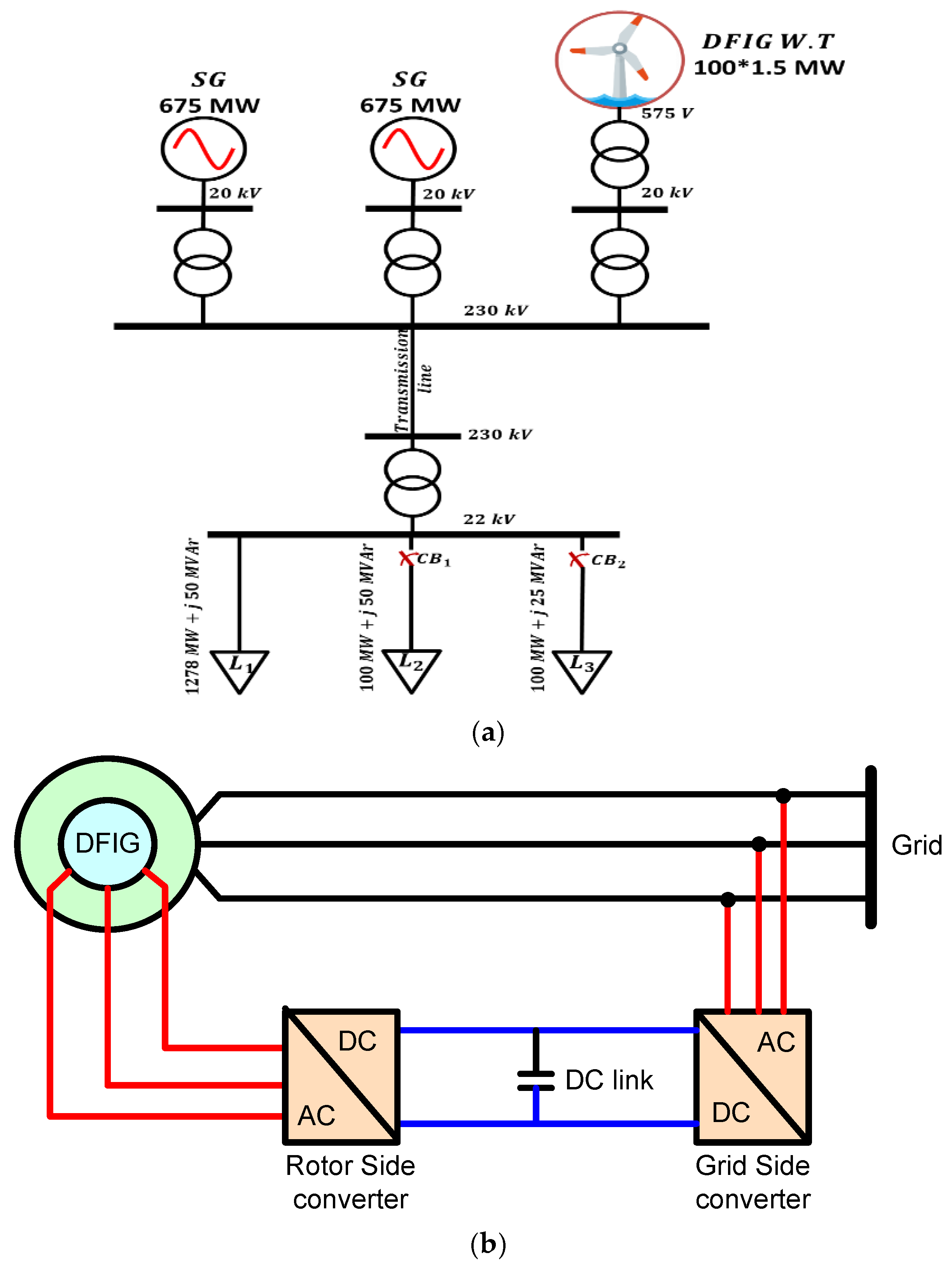
Figure 1. (a) The single-line diagram of the test system, and (b) The block diagram of the DFIG-based WT.
Processes 13 01284 g001
Figure 2. The primary frequency control scheme with the emulated inertia effect, as reported in [32].
Processes 13 01284 g002
Figure 3. (a) The proposed primary frequency control scheme using a combined PR controller and inertia emulation branch, (b) Bode diagram with various values of ω o , and (c) Bode diagram with various values of ω c .
Processes 13 01284 g003aProcesses 13 01284 g003b
Figure 4. The impact of changing the cut-off frequency of the PR controller on the system frequency response.
Processes 13 01284 g004
Figure 5. The impact of changing the resonant factor of the PR controller on the system frequency response.
Processes 13 01284 g005
Figure 6. The impact of changing the resonant frequency of the PR controller on the system frequency response.
Processes 13 01284 g006
Figure 7. The impact of changing the proportional gain of the PR controller on the system frequency response, (a) system frequency response and (b) zoomed view highlighting frequency response.
Processes 13 01284 g007
Figure 8. The impact of increasing the load on, in comparison with the traditional method reported in Ref. [32], (a) frequency response, (b) DFIG active power, and (c) ROCOF.
Processes 13 01284 g008
Figure 9. The impact of reducing the load on, in comparison with the traditional method reported in Ref. [32], (a) the frequency response, (b) the DFIG active power, and (c) the ROCOF.
Processes 13 01284 g009
Figure 10. The impact of multi-step load perturbation on frequency response, in comparison with the traditional method [32], and reported method [31]: (a) load perturbation, and (b) frequency response.
Processes 13 01284 g010
Table 1. The impact of increasing the proportional gain on the frequency deviation and overshoot.
Proportional Gain ( K p ) Frequency DropFrequency DeviationOvershoot
0.159.7050.29559.876
0.559.7420.25859.88
1.059.7760.22459.886
1.559.8080.19259.893
2.059.7950.20559.9
4.059.7460.25459.905
8.0The system becomes unstable
Disclaimer/Publisher’s Note: The statements, opinions and data contained in all publications are solely those of the individual author(s) and contributor(s) and not of MDPI and/or the editor(s). MDPI and/or the editor(s) disclaim responsibility for any injury to people or property resulting from any ideas, methods, instructions or products referred to in the content.