1. Introduction
In centerless support finishing, a workpiece is freely supported at two points on its finished outer surface without any fixed constraints from chucking [
1]. This feature offers several advantages: (1) simple, fast loading and unloading of workpieces; (2) the ability to converge roundness errors; and (3) the release of residual stresses during machining. Centerless finishing methods—including centerless grinding, shoe centerless grinding, and centerless support superfinishing—have thus become core processes for producing precision components in industries such as bearings and automotive manufacturing.
In these systems, the rotational center of the workpiece is instantaneously regenerated by the radial errors at the support points, and rounding errors at the grinding point are continuously created based on regenerative centering effects. In this process, roundness is influenced by radial errors with phase lags between the grinding point and the supporting points.
This unique rounding mechanism has been investigated for decades in centerless grinding research. Early studies focused on the geometrical roundness processes. For example, Dall [
2] first derived the workpiece movement along the cutting direction caused by roundness errors, while Yonetsu [
3] studied the generation of undulations under various setup conditions. Miyashita et al. [
4] analyzed the influence of the blade and regulating wheel on the depth of cut and identified an optimum center height angle of approximately seven degrees, a finding that was corroborated by simulations from Row et al. [
5]. Reeka [
6] developed a practical geometric stability chart, Zhou et al. [
7] analyzed the lobing generation mechanism with setup parameters, and Gallego [
8] presented an intelligent grinding stability chart based on the center height and regulating wheel speed. Krajnik et al. [
9] introduced a simulation model of work center displacement during infeed grinding under various setup parameters, and Hashimoto, Gallego, Oliveira et al. [
10] summarized the geometrical rounding mechanism along with the effects of setup conditions on roundness. Although these studies provide comprehensive insights into the geometrical rounding mechanisms in centerless grinding, the support conditions considered were limited to traditional centerless grinding operations.
Several studies have also addressed rounding simulations for shoe centerless grinding. Charmley [
11] proposed a block diagram model for shoe centerless grinding and discussed both the geometrical and dynamic rounding stabilities. Zhang et al. [
12] developed a geometric model to predict lobing generation, and Tuan [
13] investigated the effects of various shoe angle arrangements on the rounding mechanism of workpieces.
However, none of the existing rounding mechanisms are directly applicable to other regenerative centerless methods because each theory employs specific support conditions. For example, rounding mechanisms for centerless grinding typically assume a limited range of blade angles and workpiece center heights, while studies on shoe centerless grinding employ a wide range of shoe setup angles. Due to the lack of common setup parameters between centerless grinding and shoe centerless grinding, the rounding mechanisms developed in these studies are not directly transferable. Furthermore, current mechanisms do not extend to other regenerative centerless methods, such as centerless support superfinishing. Therefore, a generalized rounding mechanism applicable to all regenerative centerless methods is required.
This paper aims to develop a generalized theory of the geometrical rounding mechanism that can be universally applied across all regenerative centerless methods. It is important to note that this geometrical rounding theory is applicable only when the grinding system is dynamically stable. In contrast, for unstable grinding systems exhibiting self-excited chatter vibrations [
14], a dynamic rounding theory should be used. While the geometrical rounding mechanism is influenced solely by the support conditions of the workpiece, the dynamic rounding mechanism is governed by various factors, including the dynamic compliances of the grinding machine, the force generation associated with material removals and the characteristics of grinding and regulating wheels. This paper focuses exclusively on the geometrical rounding mechanism.
The paper describes the relationships between support conditions and rounding stability using a newly introduced parameter, the generalized center height angle. The effects of roundness errors at the support points on the depth of cut are clarified, and the rounding stability for each undulation on the workpiece is examined. Additionally, the geometrical filter effects created by the interference of the grinding wheel and the contact length of the support surfaces are discussed. These filter effects significantly reduce the roundness components of high-order undulations. It is demonstrated that the developed theory can accurately predict the occurrence of unstable undulations and provide rounding stability for every undulation across all regenerative centerless methods. The predicted rounding instability is subsequently verified through experimental testing.
2. Regenerative Centerless Support and Influence Factors
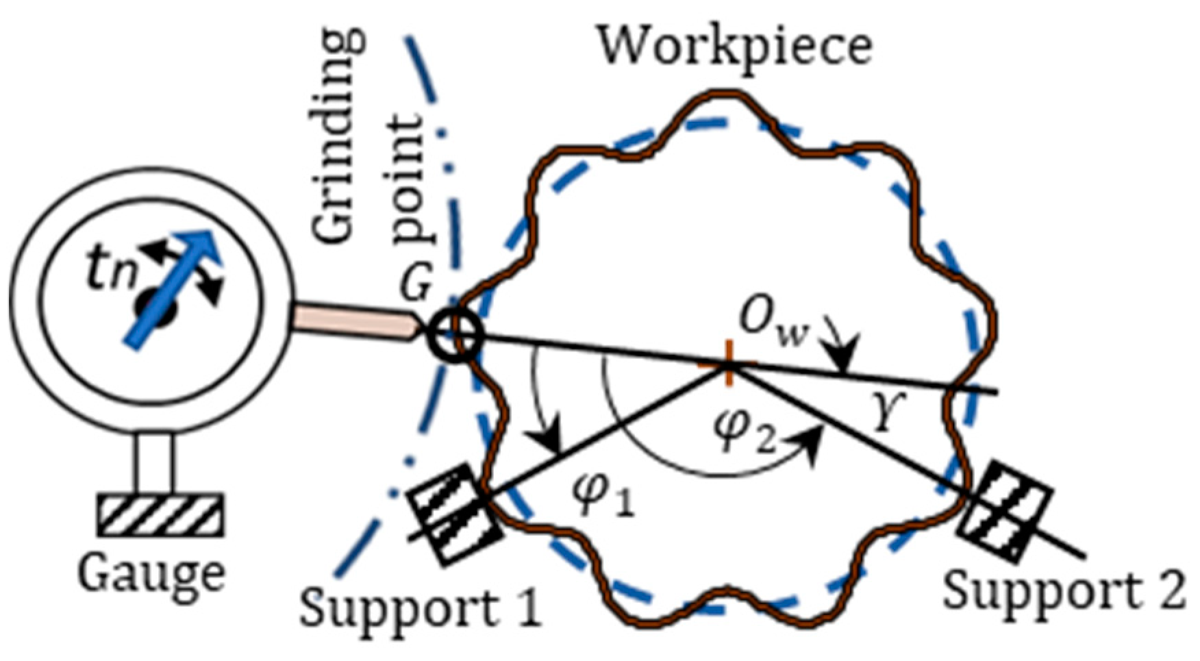
In a centerless support, as shown in
Figure 1, a workpiece is freely supported at two points of the outer surface without any fixed restriction. A dial gauge is set at the point
G, corresponding to the grinding point. The work rotational center is instantaneously regenerated by the radial errors of the workpiece at support 1 and support 2. The gauge reading continuously varies based on the regenerated center
Ow. The gauge reading
tn is affected by the radial errors of the support points with the phase lags
φ1 and
φ2. The angle,
ϒ (
ϒ = π −
φ2), is the center height angle.
Figure 2 shows finishing methods applying the principle of regenerative centerless support. These centerless methods are the core processes for the mass production of precision components.
The influence factor,
ε, is defined as the ratio of the roundness error at a support point to the depth of cut at the grinding point
G. Originally introduced for centerless grinding as a function of the blade angle and work center height [
4], this parameter has been generalized here for application to other centerless support methods. The generalized influence factors,
ε1 and
ε2, represent the effect of a unit roundness error at support 1 and support 2, respectively, on the depth of cut at point
G, and are expressed as:
Figure 3a,b illustrate how the influence factors
ε1 and
ε2 vary with the support angles
φ1 and
φ2, respectively. Under typical centerless grinding conditions, the ranges of the influence factors are 0 <
ε1 < 0.2 and 0.9 <
ε2 < 1.0, indicating that the roundness error at support 2 has a significant impact (approximately 90%) on the grinding point
G, whereas the impact from support 1 is minimal (less than 20%). In contrast, under typical shoe centerless grinding conditions, the ranges are 0.1 <
ε1 < 0.4 and 0.85 <
ε2 < 0.95. This suggests that the influence of support 1 increases (exceeding 30%) and cannot be neglected in shoe centerless grinding.
3. Gauge Reading and Generalized Center Height Angle
Since the mean diameter,
r0, and the center offset,
r1, do not represent the roundness error, the roundness
r(
φ) of the workpiece is expressed as a summation of harmonic components corresponding to the undulations per revolution (
n-UPR):
where
φ is the rotational angle,
n represents the number of undulations along the circumference, and
rn and
τn are the amplitude and phase of the n-UPR component, respectively.
When the workpiece rotates under regenerative centerless support, the gauge run-out
t(
φ) at the grinding point
G can be expressed as:
where the first term represents the roundness error at the grinding point
G. The second term accounts for the reduction in displacement due to the roundness error at support 1. The third term reflects the increase in displacement influenced by the roundness error at support 2. Thus, the gauge run-out
tₙ(
φ) for the
n-UPR amplitude
rn at point
G is given by:
When the gauge is replaced by a grinding wheel, the gauge reading (or total indicator reading) corresponds to the depth of cut. In the case where tₙ = 0, it indicates that the amplitude of the n-UPR component cannot be reduced by the grinding operations.
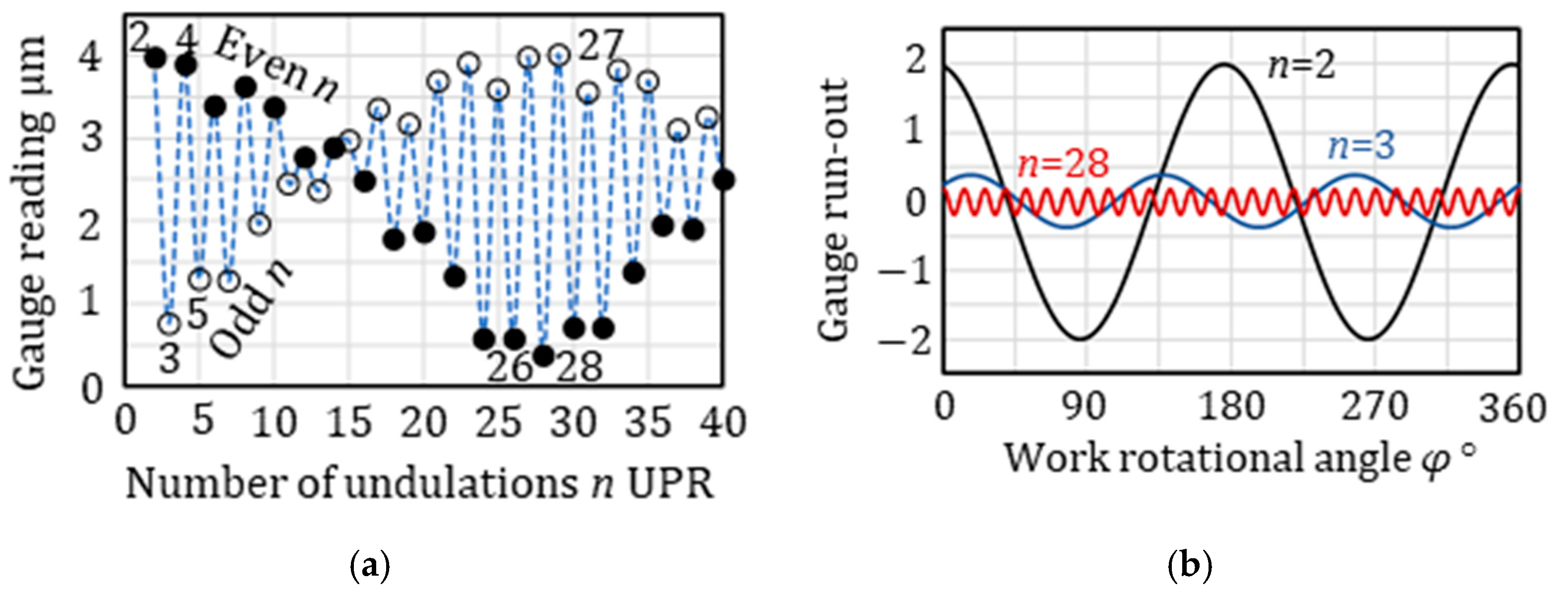
Figure 4a,b show the gauge reading of the
n-UPR (amplitudes of 1 μm) components and the gauge run-out for specific components under the center height angle
ϒ = 6.4°. Each undulation
n has its own gauge reading. The reading is maximized at 2 UPR and the run-out becomes ±2.0 μm. At 3 UPR, the gauge reading becomes small (0.76 μm), and at 28 UPR, the reading is minimized and the run-out is close to zero (0.37 μm).
When a workpiece is ground under the support condition (ϒ = 6.4°), the roundness error of n-UPR associated with a higher gauge reading, like 2 UPR or 27 UPR, is rapidly reduced. However, the error associated with the small gauge reading (28 UPR in this case) is a geometrically unstable undulation, ng, which is difficult to remove within a limited time by grinding.
In addition to
Figure 4a with
ϒ = 6.4°,
Figure 5a,b describe the effect of the center height angle
ϒ on the gauge reading. At the lower angle
ϒ = 3° (
Figure 5a), the smaller odd undulations minimize the values of the gauge reading, while the smaller even undulations maximize the values. This means that with small, odd undulations (e.g., 3, 5, 7 UPR), it becomes difficult to quickly reduce the roundness errors; however, the errors for small, even undulations (e.g., 2, 4, 6 UPR) can be rapidly reduced by grinding operations. The odd 3 UPR becomes the unstable undulation,
ng, because it is the smallest gauge reading.
At the higher angle
ϒ = 10° (
Figure 5b), the values of the gauge reading for even 18 UPR and 20 UPR are minimized. Also, the odd 35 UPR and 3 UPR provide small values for the reading. When grinding with
ϒ = 10°, the 18 UPR and/or 20 UPR appear as unstable undulations and the odd 35 UPR and/or 3 UPR may possibly appear.
As shown in
Figure 4 and
Figure 5, the unstable undulations,
ng, are varied by the center height angle
ϒ. It is difficult to predict the unstable undulations by the above analysis. Therefore, a different approach is required to generalize the rounding mechanism.
Assuming
ε1 = 0,
ε2 = 1 and substituting
= π-
ϒ, Equation (5) can be approximately written by:
In the case of an odd undulation
no UPR, the gauge run-out
todd(
φ) can be expressed by:
In the case of an even undulation
ne UPR, the gauge run-out
teven(
φ) can be expressed by:
Equations (6)–(8) indicate that the gauge reading tn is mainly affected by The parameter is named the “generalized center height angle”.
4. Rounding Mechanism and Unstable Undulation
Figure 6a shows the gauge reading versus
nγ, calculated using Equation (5). The unstable undulations are identified as 3 UPR, 42 UPR, 44 UPR, and 89 UPR.
Figure 6b demonstrates that Equations (6)–(8) provide sufficiently accurate gauge readings—with maximum errors of less than 5%—and are effective for predicting the geometrical unstable undulation
ng.
Since todd = 0 at noϒ = 0, 2π, 4π,···, the odd unstable undulations, ngo, for ϒ = 4° are determined by ngo = [0/ϒ]o = [0/4]o = 3 and ngo = [2π/ϒ]o = [360/4]o = 89, where [X]o denotes the closer odd integer ( to the value X. Similarly, since teven = 0 at neϒ = π, 3π, 5π, …, the even unstable undulations are nge given by nge = [π/ϒ]e = [180/4]e = 44 UPR and/or 46 UPR, where [X]e represents the closer even integer to the value X.
In the approximated solutions shown in
Figure 6b, the odd 3 UPR and 89 UPR and the even 44 UPR and 46 UPR are unstable undulations. Among them, the even 44 UPR is the most difficult undulation for reducing the roundness errors by grinding because of the smallest value of the gauge reading.
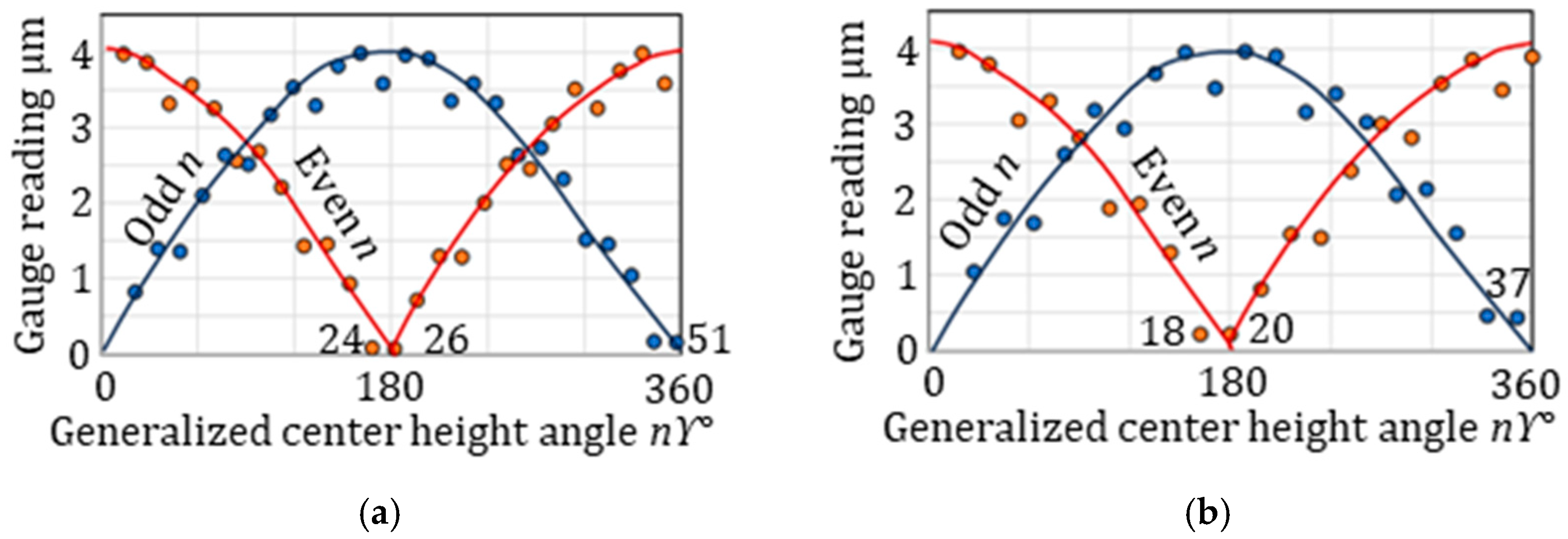
Figure 7a,b shows the gauge reading with respect to the generalized center height angle. In the case of a center height angle
ϒ = 7° (
Figure 7a), the even unstable undulation,
nge, appears at 24 UPR and/or 26 UPR, corresponding to [180/7]
e, while the odd unstable undulation,
ngo, occurs at 51 UPR, given by [360/7]
o. For a higher center height angle of
ϒ = 10° (
Figure 7b), the even unstable undulation is 18 UPR, derived from [180/10]
e. Additionally, an even unstable at 20 UPR is predicted by Equation (5). The odd unstable undulation,
ngo, is 37 UPR, determined by [360/10]
o.
The rounding mechanism in regenerative centerless supports is generalized by analyzing the gauge reading in terms of the generalized center height angle, denoted as [
nϒ] (see
Figure 6a,b), rather than the undulation [
n] (
Figure 5a,b). The generalized center height angle [
nϒ] serves as a key parameter that not only determines the geometrically unstable undulations but also dominates the rounding stability of the regenerative centerless support system.
All roundness errors of the
n components are reduced during the grinding process, except for those corresponding to unstable undulations. The larger the gauge reading of an undulation, the lower its roundness error. The roundness index (
RI) is defined as:
where
TIRmax is the maximum gauge reading for all undulations.
TIR(
n) is the gauge reading for the specific
n UPR.
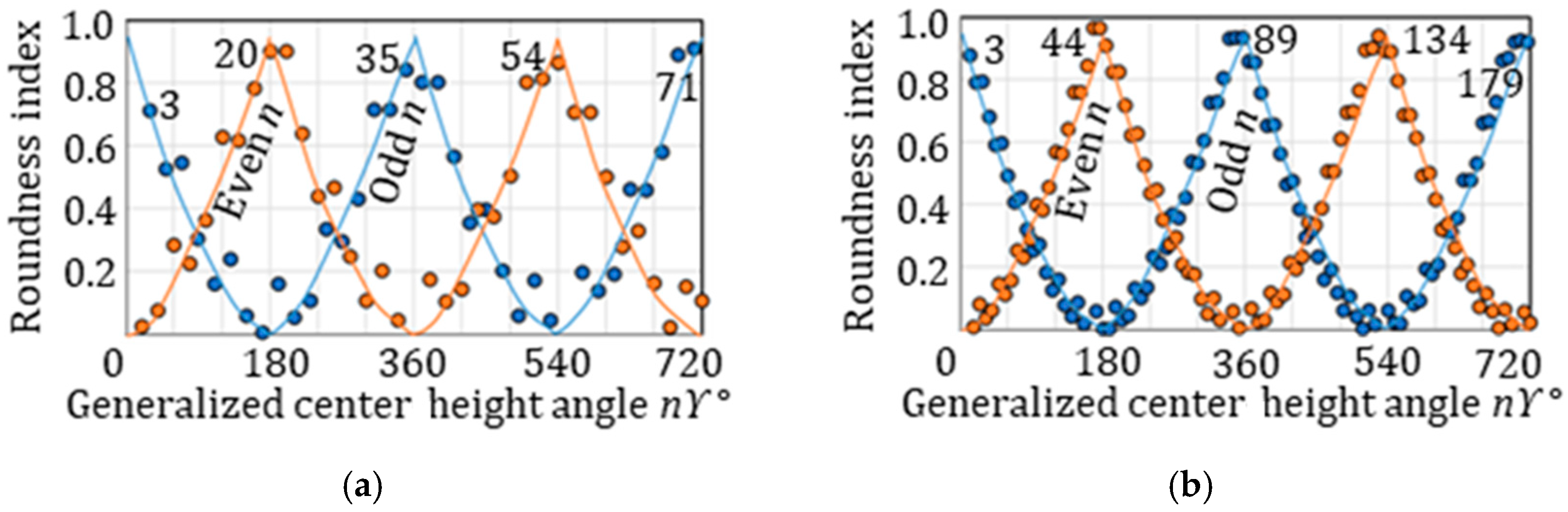
Figure 8a,b show the roundness index
RI with the range (0 ≤
nϒ ≤ 720°) of the generalized center height angle. In the case of
ϒ = 4° (
Figure 7a), the
RI is maximized at odd undulations of 3 UPR, 89 UPR and 179 UPR and at even undulations of 44 UPR and 134 UPR. In the case of
ϒ = 10° (
Figure 8b), the maximized odd undulations are 3 UPR, 35 UPR and 71 UPR, and the even undulations are 20 UPR and 54 UPR. These undulations correspond to the unstable undulations,
ng, and the roundness errors are exacerbated.
5. Effect of Geometrical Filters on Rounding Mechanism
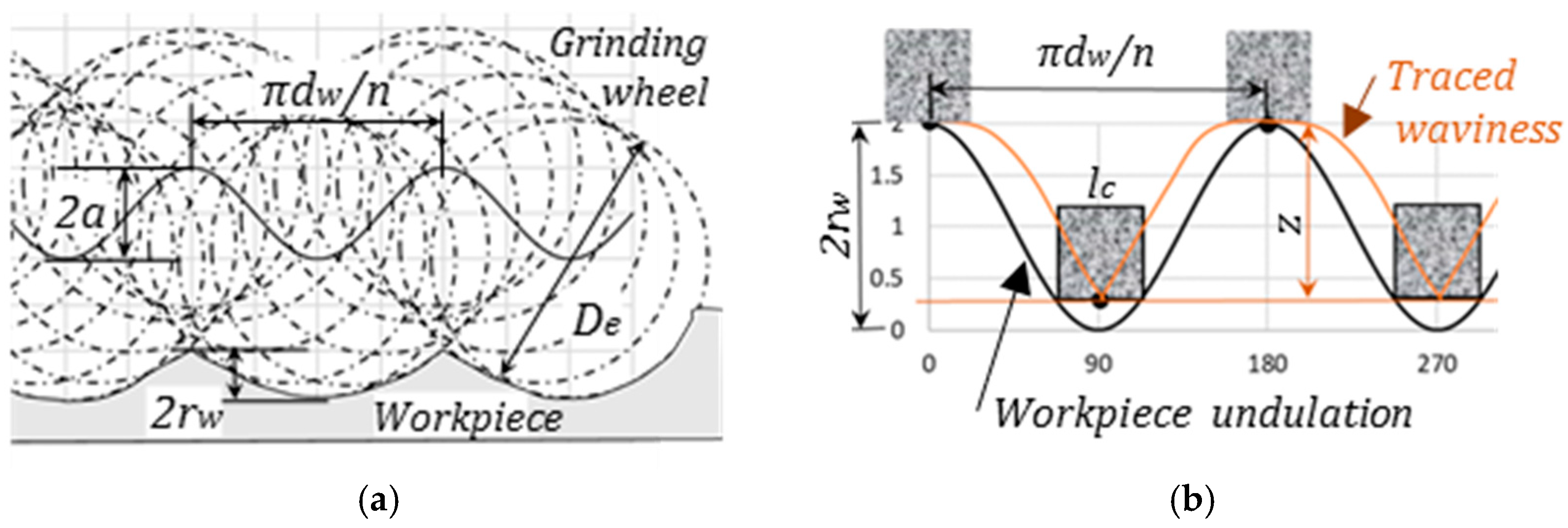
The vibration of relative displacement between the grinding wheel and the workpiece is transferred on the work surface as an envelope curve with an undulation.
Figure 9a shows the geometrical filter effect due to the interference of the grinding wheel. The transfer function
G(
n) is defined as the ratio
rw/
a of the amplitudes 2
a of the relative vibrations to the height 2
rw of the generated undulation
n [
15].
where
De is the equivalent wheel diameter, defined as 1/
De = 1/
ds + 1/
dw. Here,
ds and
dw denote the grinding wheel diameter and the workpiece diameter, respectively. The cutoff undulation
ncs is defined as the undulation when the function
G becomes −3 dB (0.708).
When the workpiece contacts the support surface with a contact length
lc [
16] as shown in
Figure 10b, the transfer function
G(
n), defined as the ratio of the height
z of the traced waviness to the total amplitudes 2
rw of the workpiece undulation
n, can be expressed by:
The cutoff undulation
ncr is represented by:
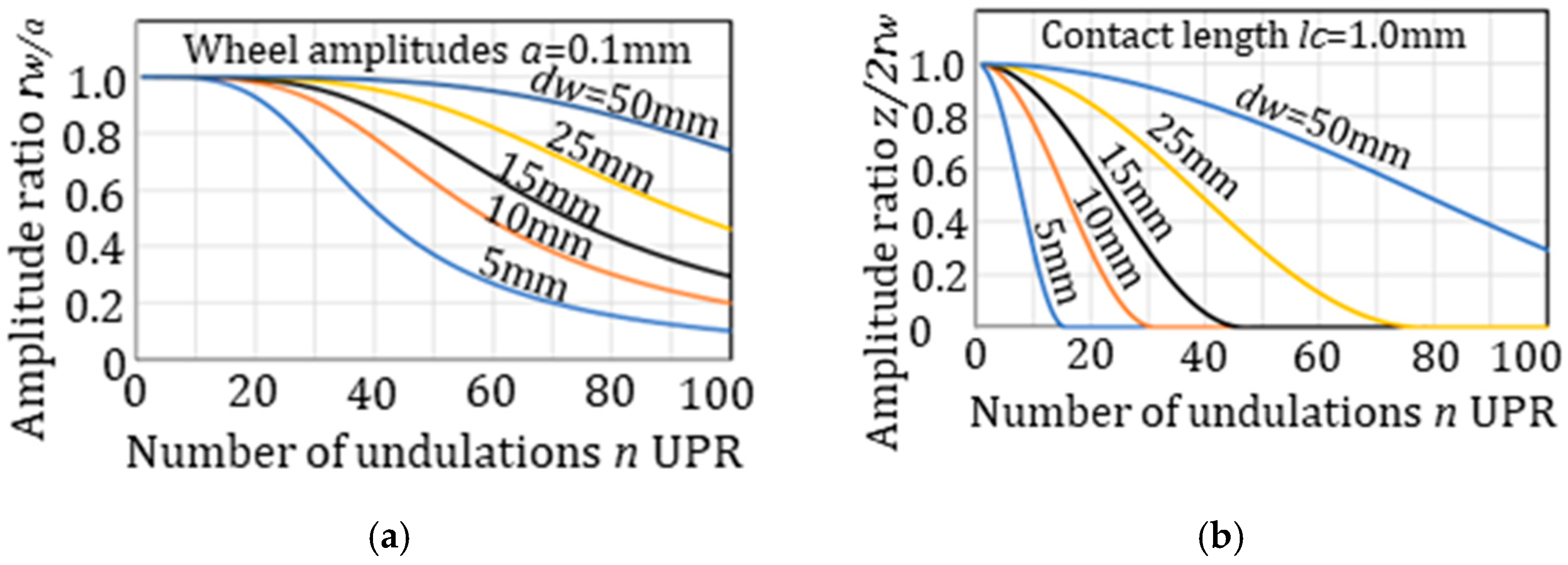
Figure 10a,b show the influence of the work diameters
dw on the geometrical filter effects. The cutoff undulations
ncs and
ncr with
dw = 25 mm are 72 UPR and 29 UPR. With
dw = 10 mm,
ncs and
ncr are 45 UPR and 11 UPR, respectively. The cutoff UPRs reduce with reduced workpiece diameter. The filter effects become obvious where the wheel amplitudes,
a, become larger and the contact length,
lc, increases.
The roundness errors of components beyond the cutoff undulations are significantly reduced due to the geometric filtering effect. As a result, the roundness errors of undulations higher than the cutoff undulations can be neglected, ensuring that roundness concerns are no longer affected by unstable undulations.
Figure 11a,b show the effects of the geometrical filters on the roundness index
RI. These are compared to
Figure 8a,b, which represent no-filter effects. As the cutoff
ncr = 34 UPR and
ncs = 56 UPR under these conditions, it is predicted that the appearance of unstable undulations will be suppressed over 34 UPR.
In the case of
ϒ = 4° (
Figure 11a), the odd undulation of 3 UPR has the maximum
RI among all the undulations, with the second-highest being the odd 5 UPR. The odd 3 UPR appears after grinding operations. The other possible undulation is 5 UPR. The index
RI of even undulation of 44 UPR is reduced by the filter effects and will not appear due to the low
RI values.
In the case of
ϒ = 10° (
Figure 11b), the even undulation of 20 UPR appears, possibly in conjunction with 3 UPR. The undulation of 35 UPR does not appear due to the filter effects.
6. Effect of Center Height Angle on Roundness
The range of the center height angle is 3° ≤
ϒ ≤ 11° in normal centerless grinding operations and 7° ≤
ϒ ≤ 24° in normal shoe centerless grinding operations.
Figure 12 shows the roundness index
RI, taking into account the filter effects under the wide range of the center height angle
ϒ. The unstable undulation
ng that gives the maximum
RI value varies in the center height angle
ϒ.
In the case of the small angle (ϒ < 5°), the odd 3 UPR provides the greatest RI and the 3 UPR appears as an unstable undulation ng after grinding operations.
In the case of the higher angle (ϒ ≥ 5°), an even undulation given by [180°/ϒ°]e provides the greatest RI, and the even UPR appears after grinding operations. For instance, at the center height angle ϒ = 8.5°, even 22 UPR appears, corresponding to [180/8.5]e = [21.2]e = 22.
In the case of the high center height angle ϒ > 11°, the RI of an odd UPR becomes close to the RI of the even UPR, or in some cases becomes greater than the even UPR’s RI. Under this condition, there are two possibilities. One is the appearance of an even unstable undulation nge given by [180°/ϒ°]e. The other is the appearance of an odd unstable undulation ngo given by [360°/ϒ°]o. For instance, at ϒ =22°, either even 8 UPR or odd 17 UPR will appear after grinding because of [180°/22°]e = 8 or [360°/22°]o = 17, respectively.
The
RI of 3 UPR decreases with increases in the center height angle
ϒ. On the other hand, as the general trend, the
RI of the even unstable undulation increases with increased
ϒ. There is a cross point around
ϒ = 6~7°. It means that there is an optimum center height angle that minimizes the roundness errors. Previous studies have reported that the optimum center height angle exists in the neighborhood of
ϒ = 7° [
17,
18].
As the filter effects significantly reduce the roundness components for undulations above the cutoff threshold, the appearance of unstable undulations can be summarized as follows:
At a low center height angle (ϒ < 5°), an odd unstable undulation (3 UPR) appears.
At a high center height angle (ϒ ≥ 5°), an even unstable undulation is observed, with the order given by [180/ϒ]e.
At an even higher center height angle (ϒ > 11°), an odd unstable undulation is observed, with the order given by [360/ϒ]o.
In practice, to achieve better roundness, it is advisable to avoid the following conditions:
7. Experimental Validation
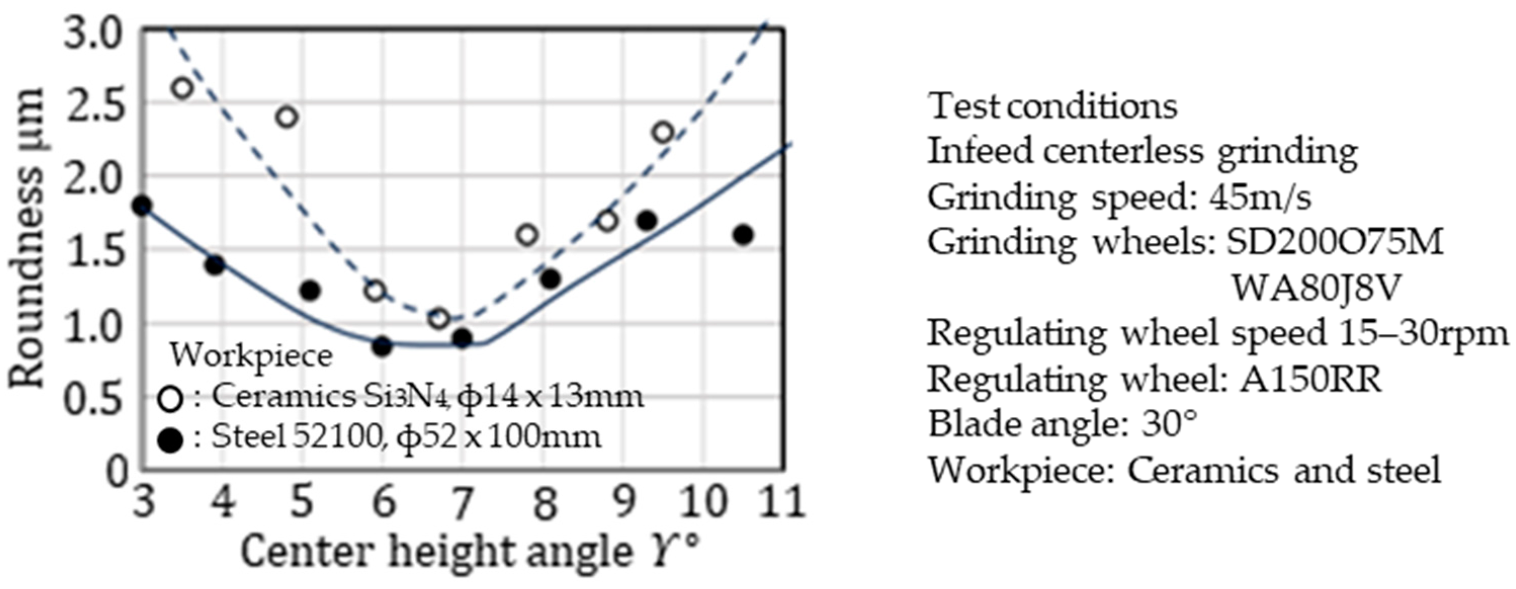
Figure 13 presents the experimental results for infeed centerless grinding of cylindrical rollers made of steel (through-hardened 52100) and ceramic (Si
3N
4). For ceramic grinding, a diamond grinding wheel equipped with a rotary diamond truer was used, while for steel roller grinding, an Al
2O
3 grain vitrified-bonded grinding wheel dressed in a single-point diamond was employed. The regulating wheels used were rubber-bonded A150RR, and 30° blades were utilized during the grinding tests. In both cases, the roundness errors were minimized at a center height angle of approximately 6–7°. These test results agree well with the theoretical predictions shown in
Figure 12.
Table 1 summarizes the grinding conditions for the experimental tests of centerless grinding (see
Figure 14). The process used is infeed centerless grinding with a water-soluble coolant. The grinding machine is equipped with hydrostatic bearings on both the grinding wheel and the regulating wheel spindles. A conventional Al
2O
3 grain grinding wheel operating at 45 m/s is used, while the regulating wheel is a rubber-bonded A150RR rotating at 18 rpm. The workpiece material is through-hardened steel (HRC60) with a diameter of 30 mm and a length of 70 mm. A carbide blade with a 30° angle is applied. The specific material removal rate is 1.6 mm
3/mm·s, resulting in an overall removal rate of 112 mm
3/s.
Figure 14 displays the roundness polar charts for workpieces processed under the conditions listed in
Table 1.
Figure 14a, obtained at a low center height angle of
ϒ = 3.1°, clearly shows odd undulations (3 UPR and 5 UPR) on the roundness chart (3.4 μm), corresponding to the expected odd unstable undulations.
Figure 14b, obtained at
ϒ = 8.8°, presents a roundness chart (1.6 μm) with an even undulation at 20 UPR, as indicated by [π/
ϒ]
e = [180/8.8]
e = 20.
Figure 14c, obtained at a high center height angle of
ϒ = 11°, shows a roundness chart (0.7 μm) with an even undulation at 16 UPR, consistent with [π/
ϒ]
e = [180/11]
e = 16.
Table 2 summarizes the grinding conditions for the experimental tests of shoe centerless grinding (see
Figure 15). The process used is infeed shoe centerless grinding with a water-soluble coolant. The experiments were conducted on a #1 micro-centric shoe centerless grinding machine equipped with hydrodynamic bearings on the grinding wheel spindle. A conventional Al
2O
3 grain grinding wheel operating at 60 m/s was employed, and carbide shoes (HRV1600) were used for both the front and rear shoe positions. The workpiece material is through-hardened steel (HRC58–60) with a diameter of 110 mm and a width of 25 mm. The specific material removal rate is 1.5 mm
3/mm·s, resulting in an overall removal rate of 37.5 mm
3/s.
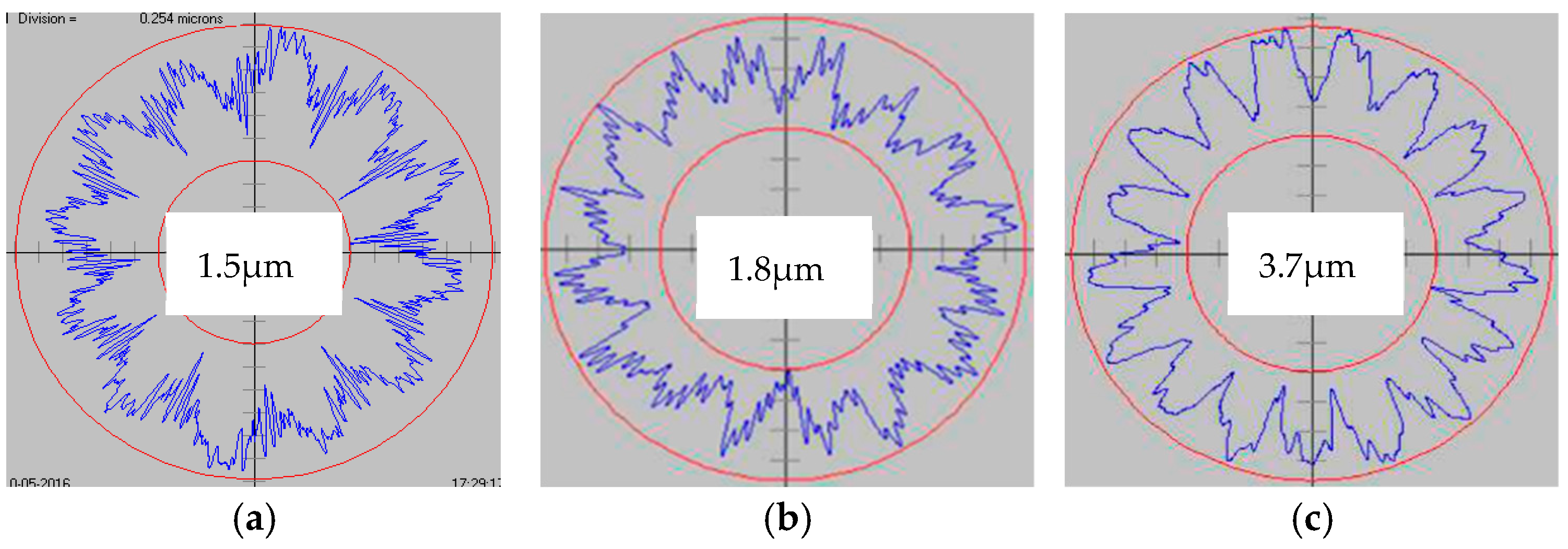
Figure 15 shows the unstable undulations observed during shoe centerless grinding operations. In
Figure 15a, obtained at a center height angle of
ϒ = 15.2°, the roundness chart (1.5 μm) displays an even undulation of 12 UPR, corresponding to [180/15.2]
e = 12. Chatter marks are evident on the chart, indicating that dynamic behavior did not significantly impact the unstable undulation in this case.
Figure 15b, obtained at a center height angle of
ϒ = 10.8°, shows a roundness chart (1.8 μm) with an even undulation of 16 UPR, corresponding to [180/10.8]
e = 16.
Figure 15c, obtained at an even higher center height angle of
ϒ = 21.3°, presents a roundness chart (3.7 μm) with an odd undulation of 17 UPR, as predicted by [2π/
ϒ]
o = [360/21.3]
o = 17. In regions where
ϒ > 11° (see
Figure 12), the unstable undulation is predicted to appear as either an even UPR, given by [π/
ϒ]
e, or an odd UPR, given by [2π/
ϒ]
o.
8. Conclusions
A generalized center height angle, [nϒ], defined as the product of the number of undulations n and the center height angle ϒ, is newly introduced. This [nϒ] parameter enables the establishment of a generalized rounding mechanism in regenerative centerless supports. The relationship between the generalized center height angle [nϒ] and rounding stability is elucidated, leading to the following clarifications regarding rounding instabilities:
An odd unstable undulation appears when [nϒ] equals 0, 2π, 4π, …
An even unstable undulation appears when [nϒ] equals π, 3π, 5π, …
Taking into account the cutoff undulations created by filter effects, the following conclusions can be drawn:
At a low center height angle (ϒ < 5°), an odd 3 UPR appears as the unstable undulation.
At a center height angle greater than 5° (ϒ ≥ 5°), an even undulation, determined by [180/ϒ°]e, appears; for example, at ϒ = 8°, [180/8]e predicts a 22 UPR.
At a high center height angle (ϒ > 11°), either an even undulation, given by [180/ϒ°]e, and/or an odd undulation, given by [360/ϒ°]o, appears; for example, at ϒ = 21°, [180/21]e predicts an 8 UPR or [360/21]o predicts a 17 UPR.
These theoretical predictions for rounding mechanisms have been experimentally verified.
As the practical tactics, to achieve better roundness, it is advisable to avoid the setup of the center height angle ϒ satisfying the following conditions:


