Abstract
Due to the high formation temperature of high-temperature reservoirs, ordinary polyacrylamide microspheres cannot meet the requirements for temperature resistance. To address the challenge of deep profile control in high-temperature reservoirs, we prepared AM/PF polymer microspheres with excellent temperature resistance through the copolymerization of water-soluble phenolic resin (PF) and acrylamide (AM). The swelling properties of AM/PF polymer microspheres were examined using a visible light microscope, SEM, and laser diffraction. The plugging and migration characteristics of the microspheres were evaluated using membrane filtration tests and sand-filled tube displacement tests. The results indicate that the average particle size of AM/PF microspheres prepared via inverse suspension polymerization is approximately 30 μm, and the swelling process is relatively slow. The microspheres take approximately 15 days to fully swell, with a volume swelling ratio of roughly 34.25. At high temperatures, the swollen microsphere dispersion system can effectively block microporous membranes with specific pore sizes. As the concentration of microspheres increases, their plugging effect gradually enhances; however, this effect diminishes as permeability increases. The AM/PF polymer microspheres exhibit excellent temperature stability along with favorable plugging and migration characteristics at specific permeabilities.
1. Introduction
Most of the oilfields in China are formed by continental deposition, the reservoir heterogeneity is serious, and the recovery rate of water drive is low. New water channels will appear after long-term water flooding, and injected water will rush along high-permeability zones [1]. Profile control technology is one of the effective means to continue development when an oilfield enters the middle- and high-water-cut stage [2,3,4]. The indoor research and field application practice of profile control and water shutoff have been carried out for many years at home and abroad. However, for a reservoir with serious heterogeneity, the effect of a traditional profile control agent is not ideal. The injected water will quickly bypass the blocked area and flow back to the original high-permeability channel, reducing the benefit of increasing production after using the profile control agent. In order to deal with the increasingly complex problem of water flooding in high-water-cut reservoirs, deep profile control technology has attracted more and more attention in recent years [5,6,7,8,9]. The deep profile control technology of polymer microspheres is a new profile control method developed in recent years [10,11,12]. Polymer microspheres have the advantages of simple synthesis, controllable product particle size, constant volume after encountering oil, and swelling in water but no dissolution compared with the existing polymer flooding. After entering the reservoir water injection layer, the microspheres can slowly absorb water to realize deep profile control and improve the wave coefficient so as to enhance oil recovery [13,14,15].
Similarly to HPAM, the thermal resistance of polymer microspheres has always been the main concern of researchers. Many scholars at home and abroad have performed a lot of research on the temperature resistance of polymer microspheres. Huang Xuebin et al. [16] obtained a series of microspheres with different particle sizes, swelling degrees, and strength according to different preparation methods. Under the conditions of formation temperature (85~90 °C) and salinity (12~15 × 104 mg/L), through the comprehensive adjustment of injection parameters of profile control and flooding, 13 of the 14 wells corresponding to polymer microsphere profile control and flooding have seen an obvious oil increase effect, with a cumulative oil increase of 3562 T. Zhao qian et al. [17,18] prepared ternary copolymer microspheres by introducing functional monomer AMPS and NVP to copolymerize with acrylamide. The microspheres can withstand temperature for 15 days at 120 °C, and after adding stabilizer, they can stabilize for more than 40 days at 130 °C. Qu Wen et al. [19] used an acrylamide monomer and a 2-acrylamido-2-methylpropanesulfonate sodium heat-resistant monomer; a physical crosslinking agent lithium saponite was added on the basis of the chemical crosslinking agent N, N-methylene double acrylamide, and the ultrafine polymer microspheres with an initial particle size of 8.5 μm were obtained by inverse emulsion polymerization. The indoor research shows that the diameter of the microspheres at 30 days at 80 °C is still maintained at 90 μm, which has good high-temperature stability. Yang [20,21] chose divinylbenzene as a crosslinking agent, AES as an emulsifier, and azo double (2-methyl acrylic nitrile) as the initiator system on the basis of an acrylamide monomer for a new type of polymer microsphere (DCA). DCA is divided into three layers in structure; the outside piece is the hydration layer, the middle layer is a crosslinked polymer layer, and the gel core is the most medial nucleus. The particle size of DCA products ranges from 0.1 μm to 30.0 μm, and DCA can be stabilized to 90 days at 115 °C. Field tests (80 to 90 °C) show that DCA is effective at reducing water and increasing oil, and it can be used in higher-temperature reservoirs. However, there are some oil fields in China, such as Huabei Oilfield, Northwest Oilfield, Shengli Oilfield, Zhongyuan Oilfield, Tarim Oilfield, etc., that are high-temperature and high-salt reservoirs with extremely rich crude oil reserves. The formation temperature of these oilfields is as high as 110–150 °C, and the salinity is as high as 11 × 104–26 × 104. The existing polymer microspheres have difficulty meeting the application requirements of these high-temperature and high-heterogeneity reservoirs because of the serious reservoir heterogeneity. Therefore, it is very urgent to develop deep profile control technology of temperature-resistant polymer microspheres with good adaptability to a high-temperature (110–150 °C) reservoir environment. Obviously, the copolymerization of water-soluble phenolic resin (PF) and acrylamide (AM) was introduced to prepare AM/PF polymer microspheres with good temperature resistance, and the plugging and migration characteristics of the microspheres were studied.
2. Experimental Section
2.1. Materials
The materials included methylthionine chloride (Shanghai Macklin Biochemical Co., LTD., 90.0%, Shanghai, China), acrylamide (AM, Shanghai Macklin Biochemical Co., LTD., Shanghai, China, 99%), sorbitan monooleate (Span80, Tianjin Guangfu Fine Chemical Research Institute, Tianjin, China, AR), 1-vinyl-2-pyrrolidinon (NVP, Tokyo Chemical Industry Limited Company, Tokyo, Japan, 99%), 2-AcrylaMide-2-Methylpropanesulfonic acid (AMPS, Shanghai Macklin Biochemical Co., Ltd., Shanghai, China, 98.0%), N,N-methylene bis acrylamide (MBA, Mclean, AR, USA), potassium persulfate (KPS, Tianjin Fuchen Chemicals, AR, Tianjin, China), anhydrous ethanol (Beijing Modern Oriental Fine Chemicals Co., Ltd., AR, Beijing, China), and 10# white oil (Fushun refinery, Industrial grade, Fushun, China). All of the above materials were used without any further purification. Deionized water was filtrated through microporous cellulose membranes with a pore size of 0.22 μm.
2.2. Synthesis Polymer Microspheres by Inverse Suspension Polymerization
A small amount of emulsifier (Span-80) was weighed and placed in a 250 mL round-bottom flask. A certain amount of white oil was added to make the mass fraction of emulsifier 4%. The emulsifier was stirred in a water bath at 50 °C for 30 min until the oil phase was clear and transparent. AM, PF, KPS, and MBA were dissolved in an appropriate amount of water in a certain proportion. The prepared oil phase was placed in a water bath pot, connected with the reaction device, stirred at a speed of 250 r/min with nitrogen flooding to drive oxygen for 30 min, and then the temperature of the water bath pot was adjusted to 25 °C. After the oil phase was cooled, the water phase was added drop by drop with a constant-pressure-drop funnel. After the water phase was added, the emulsification continued at a low temperature for 30 min. After the emulsion homogenized, the water bath temperature was adjusted to 70 °C, and the reaction temperature was maintained for 4 h. After the end of the reaction, the product reaction emulsion was demulsified with 10 times the volume of anhydrous ethanol for filtration. After repeated several times, the product was placed in a vacuum drying oven at 40 °C for 24 h, and finally the AM/PF polymer microspheres were obtained in creamy white.
2.3. Temperature Resistance Property of Polymer Microspheres
About 0.2 g of microsphere was placed in an ampoule bottle containing 40 mL deionized water, then the ampoule bottle was vacuumed and sealed. Finally, the sample was placed in a constant-temperature environment (120 °C, 130 °C, 140 °C), and then the swelling phenomenon was observed by the optical microscope along with the particle size distribution measured by the laser particle sizer. When the microspheres were almost completely degraded, the process of temperature resistance was considered finished.
2.4. SEM of Polymer Microspheres
The solid powder of AM/PF polymer microspheres was directly placed onto an electrically conductive film, the sample was sprayed with metal for 3 min, and the morphologies of the AM/PF microspheres were observed with a SEM SU8010 manufactured by the Hitachi Company of Japan (Tokyo, Japan).
2.5. Size Distribution of Polymer Microspheres
The size distribution of the swollen microspheres and solid powder were investigated with a Microtrac-S3500 laser particle size analyzer produced by the Microtrac Company (York, PA, USA) based on laser diffraction. This analysis was performed under a constant temperature (25 °C) and with the extended blue wave.
2.6. Microscopic Observation of Polymer Microsphere
One drop of the sample of swelling microspheres was placed onto the surface of a clean glass sheet for observation under an Olympus BX41 microscope manufactured by the Olympus Company (Tokyo, Japan).
2.7. TG-DSC Analysis of Polymer Microsphere
The aerobic temperature resistance of microspheres was essential for the persistence of profile control and water shutoff. At a heating rate of 10 °C per minute, the temperature performance of polymer microspheres was measured in an oxygen environment by a thermal gravimetric analyzer NETZSCH STA409PC purchased from NETZSCH Instruments Manufacturing Co., Ltd., Bavaria, Germany.
2.8. Experimental Study on Cellulose Membrane Filtration of Polymer Microspheres
The experimental method for the filtration of the AM/PF polymer microsphere solution through a cellulose membrane is described in reference [22].
2.9. Experimental Study on Plugging and Migration of Polymer Microspheres
The experimental device of microsphere plugging and migration is shown in Figure 1. The sand-filled pipe used in the experiment was customized for the laboratory. Each section of steel pipe was made of stainless steel and connected together by pipe clamps. Pressure measuring points were set on the steel pipe, and the position of the pressure measuring point can be set flexibly according to the experimental requirements. The main parameters of the sand-filled pipe are shown in Table 1. A pressure measuring point was set at the inlet end and middle section of the sand-filled pipe. Pressure sensors are installed on the pressure measuring points. The signal of the pressure sensor can be transferred to the computer in real time through the converter to realize the real-time recording of the pressure at the pressure measuring point. The slightly wetted quartz sand was placed into the sand-filling pipe and it was tamped with a steel rod to ensure close contact between the sand. The permeability of the sand-filled pipe can be adjusted by adjusting the particle size and compactness of quartz sand. During the experiment, kerosene is delivered to the storage tank filled with a solution to be injected at the set flow rate by a horizontal flow pump. Kerosene forms the liquid to be injected into the inlet end of the filled sand pipe by squeezing the piston, and then it flows out from the end of the sand pipe after flowing through the pores of the filling sand pipe. The specific steps of the displacement experiment are referred to in [23].
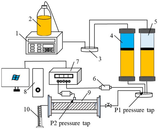
Figure 1.
Sand-packed model experimental apparatus. (1. Horizontal flow pump; 2. kerosene bottle; 3. six-way valve; 4. microsphere stirring tank; 5. water tank; 6. pressure sensor; 7. pressure signal converter; 8. computer; 9. sand-filling pipe; 10. measuring cylinder).

Table 1.
The parameters of the sand-packed model.
The sectional sand-filling pipe used in the experiment is shown in Figure 2. The length of a single sand pipe is 35 mm and the inner diameter is 25 mm. The joint of two sand pipes is padded with polytetrafluoroethylene gasket to ensure the water tightness of the whole sand pipe. The joint is pressed by a movable quick opening valve, which can withstand a pressure of 2.5 MPa at most. With this device, the plugging and migration of microspheres can be judged by the pressure changes at the inlet and middle pressure measuring points.
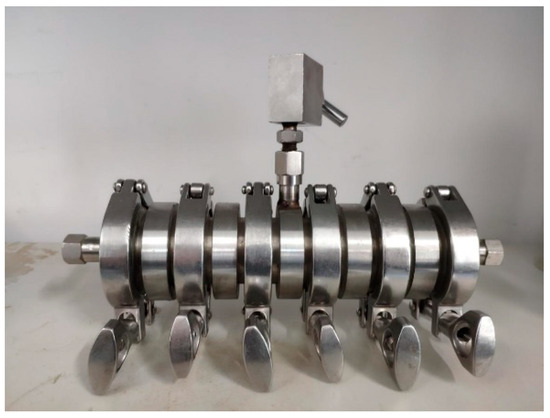
Figure 2.
Sectional sand-packed tube.
3. Results and Discussion
3.1. Morphology and Particle Size Distribution of AM/PF Polymer Microspheres
The morphology of AM/PF polymer microspheres with AM:PF = 12:8 (mass ratio) synthesized in a laboratory was observed by SEM, as shown in Figure 3. It can be seen in Figure 3 that the morphology of single microspheres can be clearly observed by enlarging the scanning electron microscope (SEM). The particle size of AM/PF microspheres is between 10 and ~30. The results show that the AM/PF microspheres have good monodispersity and a lot of protruding spheres are uniformly attached on the surface of AM/PF microspheres, which may be formed by the combination of oligomers containing more acrylamide in the reaction droplets at the later stage of balling.
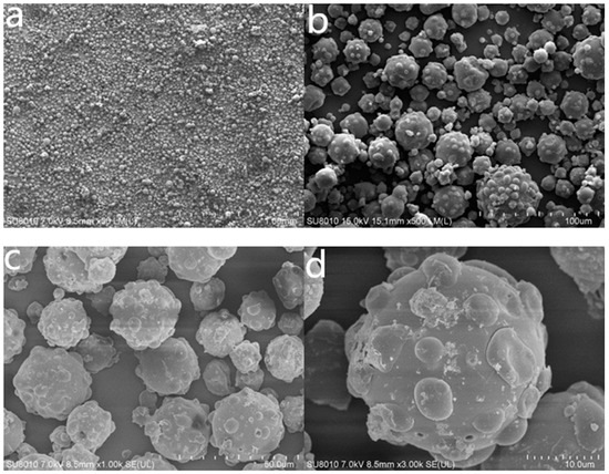
Figure 3.
Different magnification SEM photos of AM/PF microsphere powder. Magnification is (a) 50 times; (b) 500 times; (c) 1000 times; and (d) 3000 times.
In order to determine the particle size and distribution of the synthesized microspheres more accurately, the laser particle size analyzer was used to detect the particle size distribution of the samples. Because the microspheres would swell after meeting water, anhydrous ethanol was selected as the circulating phase. The measurement results are shown in Figure 4. It can be seen from the figure that the particle size distribution width of the dry microsphere powder ranges from a few microns to 100 μm, the average particle size is about 30 μm, and the monodispersity is good.
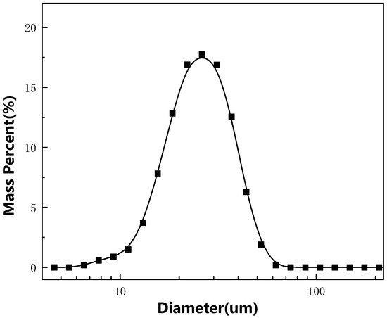
Figure 4.
Particle size distribution of AM/PF microsphere powder.
3.2. Swelling and Temperature Resistance of AM/PF Polymer Microspheres
3.2.1. Morphology of Polymer Microspheres After Swelling
In order to observe the swelling property of AM/PF microspheres more macroscopically, 2000 mg/L of AM/PF polymer microsphere solution was transferred into an ampoule bottle, and then the swelling phenomenon was observed in the oven at 140 °C. The height of the solid in the ampoule bottle without swelling and completely swelling was measured and photographed. The results are shown in Figure 5. From the photos before and after swelling, it can be seen that the height of microspheres before swelling is about 0.2 cm, while the height after 10 days of swelling at 140 °C can reach about 6.85 cm, and the macroscopic swelling multiplier is about 34.25. This indicates that AM/PF microspheres have excellent swelling properties and can meet the needs of deep profile control. In order to further observe the morphology and size of AM/PF polymer microspheres after swelling, an appropriate amount of microspheres was taken from the above ampoules and observed by an optical microscope. The results are shown in Figure 6. It can be seen from Figure 6 that the AM/PF microspheres are still relatively regular spherical after swelling, the particle size distribution of AM/PF microspheres after swelling is not very concentrated, and the size distribution is between 50 μm and 400 μm.
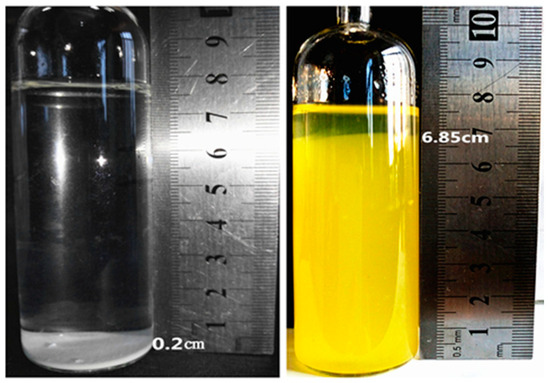
Figure 5.
The swelling before and after photos of AM/PF microspheres.
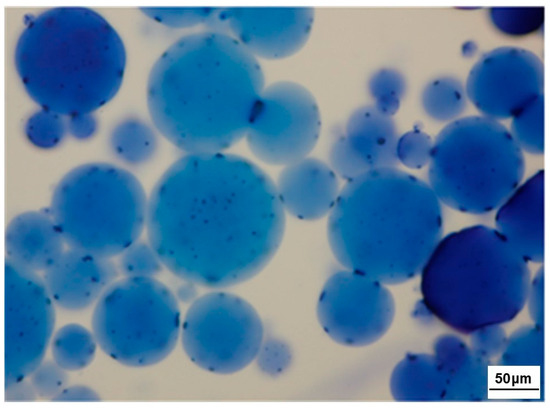
Figure 6.
Microscope photographs after 20 days of swelling of AM/PF microspheres.
3.2.2. Effect of Swelling Time
The particle size distribution of AM/PF polymer microspheres with a mass concentration of 1000 mg/L is dispersed in a 10,000 mg/L sodium chloride solution, the swelling time is different at 120 °C, and the particle size distribution of the microspheres is measured by a laser particle size meter, as shown in Figure 7. It can be seen from Figure 7 that the particle size of microspheres increases with the increase in swelling time, and the size distribution of microspheres gradually widens. The average particle size of the microspheres was 58.9 μm when swelling for 5 days. The average diameter of the microspheres reached 119.9 μm after 15 days of swelling. The average size of microspheres was 122.1 μm when swelling for 30 d, and the size distribution of microspheres after 15 d and 30 d swelling was almost the same, indicating that the swelling of microspheres was almost complete after 15 d of swelling. The results showed that the particle size of the microspheres was mainly distributed in the range of 60 μm–200 μm at 120 °C for 15 d and 30 d compared with the no-swelling microspheres, and the diameter of the microspheres after swelling increased by five times. This indicates that the swelling process of AM/PF microspheres is different from that of acrylamide microspheres. The swelling time of AM/PF microspheres is shorter than that of acrylamide microspheres. The swelling process of the microspheres will no longer enter the deep part of the reservoir, and it will take about a day to realize the swelling process of the deep part of the reservoir. The AM/PF microspheres first experienced the water swelling process in water. In 0–15 days, with the extension of the swelling time, water molecules continued to enter the microspheres. During this period, the swelling effect of water on the microspheres was obvious, which made the average particle size of the microspheres increase. After 15–30 days, the AM/PF polymer microspheres had good temperature resistance and were not easy to degrade after a long time of swelling. During this period, the microspheres reached complete swelling and gradually reached swelling equilibrium. At this time, the particle size of AM/PF microspheres remained basically unchanged. It also shows that AM/PF polymer microspheres have good high-temperature stability and are suitable for profile control and water shutoff in high-temperature reservoirs.
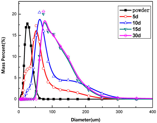
Figure 7.
Effect of swelling time on particle size distribution of AM/PF microspheres. (CAM/PF = 1000 mg/L, T = 120 °C, CNaCl = 10,000 mg/L).
3.2.3. Effect of Swelling Temperature
Figure 8 shows the particle size distribution of AM/PF polymer microspheres with a mass concentration of 1000 mg/L dispersed in a sodium chloride solution with a mass concentration of 10,000 mg/L and swelling at 100 °C, 120 °C, and 140 °C for 15 days, respectively. It can be seen from Figure 8 that the size distribution of the swelling microspheres at different temperatures is different. With the increase in swelling temperature, the size of microspheres gradually increased and the size distribution became wider. At the same swelling time, with the increase in swelling temperature, the percentage of large-size microspheres increased, and the swelling speed of microsphere dispersion system was faster at higher temperatures. This is because the higher the temperature is, the more active the water molecules are and the easier it is to enter the network structure of the microspheres. The more easily the intertwined polymer molecular chains are opened, the faster the microspheres swell and the larger the particle size is. This further indicates that AM/PF polymer microspheres have good temperature stability.
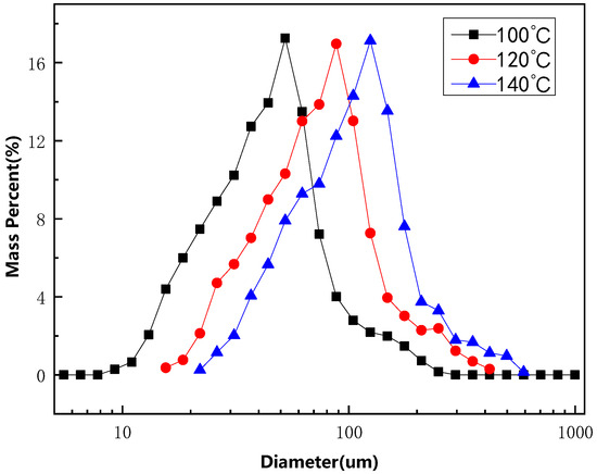
Figure 8.
Effect of temperature on diameter of AM/PF microspheres. (CAM/PF = 1000 mg/L, T = 120 °C, CNaCl = 10,000 mg/L, 15 d).
3.3. TG-DSC Analysis of AM/PF Polymer Microspheres
TG-DSC analysis of AM/PF microspheres and AM microsphere dry powder was carried out by the NETZSCH instrument in Germany. The results are shown in Figure 9 and Figure 10. It can be seen from Figure 9 that the weight loss curve of AM/PF microspheres is significantly different from that of AM microspheres obtained only by monomer AM polymerization; particularly in the curve between 250 and 350 °C, the weight loss rate of AM microspheres is much higher than that of AM/PF microspheres. It can also be seen from the DSC curve in Figure 10 that there is an obvious endothermic peak of AM microspheres, which indicates that the temperature resistance of AM microspheres without PF is poor, and the molecular chain fracture of polyacrylamide occurs at lower temperatures. In the temperature range of 350–450 °C, the weight loss of AM microspheres and AM/PF was larger and faster. There were two endothermic peaks in the DSC curve in the corresponding temperature range, which indicated that not only was the molecular chain of polyacrylamide broken but the phenolic resin structure in the microspheres had begun to fracture. When the temperature reached 680 °C, the remaining mass ratios of the two kinds of microspheres were 35.14% and 23%, respectively (i.e., AM/PF microspheres > AM microspheres). The results show that AM/PF polymer microspheres have great advantages over AM microspheres in temperature resistance.
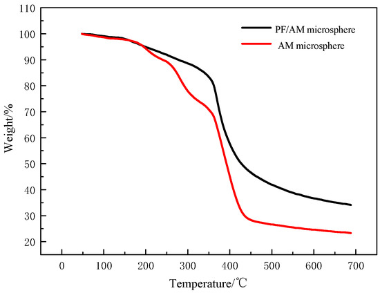
Figure 9.
TG curve of microspheres with different crosslinking agents.
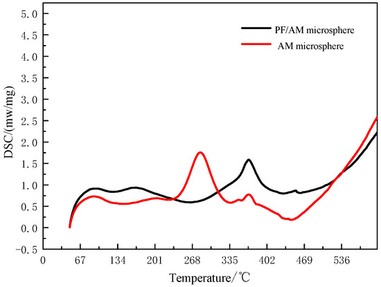
Figure 10.
DSC curve of microspheres with different crosslinking agents.
3.4. Plugging Characteristics of AM/PF Polymer Microspheres on Microporous Membrane
3.4.1. Effect of Swelling Time on Plugging Effect of Microspheres
In order to investigate the effect of swelling time on the plugging effect of AM/PF polymer microspheres, the microspheres swelled at 120 °C for 5 d, 10 d, 15 d, and 30 d were diluted to 500 mg/L with deionized water for a filtration experiment. The pore size of the microporous membrane was 5 μm, and the filtration pressure was set to 0.1 MPa. The relationship between filtrate quality and filtration time was recorded during the experiment. The results are shown in Figure 11. It can be seen from Figure 11 that the time required for the microspheres with different swelling times to filter 20 g filtrates is different. For the microspheres with a swelling time of 30 days, the blocking effect is the best. The longest time for filtering 20 g of filtrate is about 55 min, followed by swelling for 15 d, 10 d, and 5 d. The plugging ability of microspheres with different swelling times has obvious differences, which is because with the extension of swelling time, the particle size of polymer microspheres increases, and the plugging effect of microspheres is also gradually enhanced.
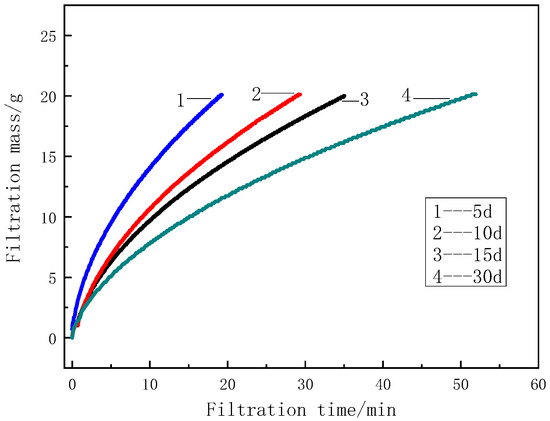
Figure 11.
Effect of swelling time on the plugging effect of AM/PF microspheres. (Cmicrospheres = 500 mg/L, T = 120 °C, CNaCl = 10,000 mg/L).
3.4.2. Effect of Swelling Temperature on Plugging Effect of Microspheres
In order to investigate the effect of swelling temperature on the plugging effect of F microspheres, AM/PF polymer microspheres were swelled at 100 °C, 120 °C, and 140 °C for 15 days and then diluted to 500 mg/L with deionized water for a filtration experiment. The pore size of the microporous membrane was 5 μ m and the filtration pressure was set to 0.1 MPa. The variation in filtrate quality with time was recorded during the experiment. The experimental results are shown in Figure 12. It can be seen from Figure 12 that the effect of the 15 d swelling microsphere on the filtration membrane with a pore diameter of 5 μm is different under different swelling temperatures. With the increase in swelling temperature, the filtration time gradually increases. The filtration time of f-microspheres swelling at 140 °C was the longest, reaching about 70 min. The filtration time of f-microspheres was the shortest at 100 °C, which was about 45 min. This is because the swelling rate of microspheres varies greatly at different swelling temperatures. The higher the temperature is, the more intensely the water molecules move. The easier it is to enter the network structure of the microspheres, the easier it is to open the entangled polymer molecular chains, the faster the swelling of microspheres, and the larger the particle size. Therefore, the plugging effect is better.
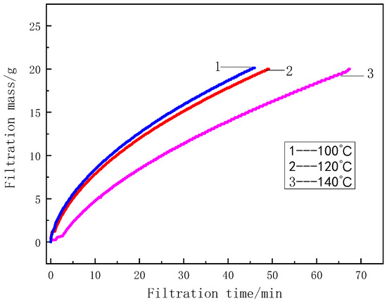
Figure 12.
Effect of swelling temperature on the plugging effect of AM/PF microspheres. (Cmicrospheres = 1000 mg/L, 15 d, CNaCl = 10,000 mg/L).
3.5. Plugging Characteristics of AM/PF Polymer Microspheres for Sand-Filled Pipe
3.5.1. Effect of Microsphere Concentration on Plugging Effect of Packed Sand Pipe with Microsphere
Figure 13 shows the plugging pressure curves of different concentrations of a microsphere dispersion system passing through a sand-filled pipe with a permeability of about 0.44 μm2. It can be seen from the figure that when the mass concentration of microspheres is 500 mg/L, with the continuous injection of microspheres, P1 first rises steadily, then fluctuates, and then rises to 52 kPa after the injection of microspheres. P2 remained unchanged for a period of time and then rose steadily. When 2 VP was injected into the microspheres, it increased to 13 kPa. In the secondary water drive stage, P1 decreased rapidly and finally stabilized at 20 kPa. P2 was slightly stable at first, then decreased steadily, and finally stabilized at 7 kPa. The 500 mg/L microsphere first forms a plugging at the entrance and then injects the microspheres to make P1 rise continuously, and the microsphere will be extruded and deformed. When the pressure gradient is reached, the microspheres will pass through the pore throat of the sand pipe and move forward to achieve the plugging of the middle pore throat of the sand pipe, making P2 rise. P2 rises steadily at first, then fluctuates, indicating that when a large number of microspheres enter the pore throat, it will go through the process of plugging, migration, and then plugging.
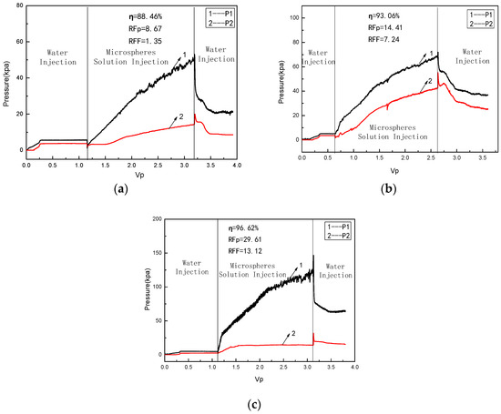
Figure 13.
Relation between pressure and injection volume (120 °C, 15 d, Q = 1.0 mL/min, CNaCl = 10,000 mg/L). (a) CAM/PF = 500 mg/L, K = 0.42 μm2; (b) CAM/PF = 1000 mg/L, K = 0.44 μm2; (c) CAM/PF = 2000 mg/L, K = 0.46 μm2.
However, when the mass concentration of microspheres was 2000 mg/L, with the continuous injection of microspheres, P1 first increased steadily to 23 kPa and then rose to 120 kPa after 2 VP injection. P2 increased slowly to 14 kPa at first, then remained unchanged. In the stage of secondary water drive, P1 first drops rapidly to 70 kPa, then continues to drop steadily to 61 kPa and remains stable. P2 remained unchanged. With the injection of 2000 mg/L microspheres, the microspheres formed plugging at the entrance. When the pressure gradient reached a certain degree, migration occurred, but the subsequent P2 was no longer changed. The rise in P1 fluctuation indicated that some of the microspheres still moved forward, but the migration of microspheres was very small, and they did not migrate to the middle of the sand pipe to form plugging.
With the increase in injection concentration, the plugging rate of the sand pipe increases gradually, which indicates that the plugging ability of the system is increasing but the migration ability of the microspheres is weakened. The reason is that with the increase in the concentration of microspheres, more and more microspheres enter the sand tube and more pore throats will be blocked, so the plugging ability will be enhanced gradually. The number of microspheres transported in the sand tube increases with the increasing concentration of the microsphere dispersion system, and the migration ability of microspheres increases. But when the mass concentration reaches 2000 mg/L, the number of microspheres in the dispersion system is too much, and a large number of microspheres will “compact” the microspheres injected in front of them after injection, which leads to the formation of filter cake at the inlet end of microspheres, which makes it difficult to move forward, so the migration ability of microspheres is weakened.
3.5.2. Effect of Sand Pipe Permeability on the Effect of Plugging Sand Pipe with Microspheres
Figure 14 shows the plugging pressure curve of the microsphere dispersion system swelling at 120 °C for 15 d on sand-filled pipes with different permeabilities. It can be seen from the figure that when the permeability of the sand tube is 0.90 μm2, P1 first fluctuates and then rises steadily with the continuous injection of microspheres and then rises to 13 kPa after 2 VP of the microsphere dispersion system is injected. P2 increases slightly. In the secondary water drive stage, P1 decreases rapidly and then stabilizes at 5 kPa. P2 decreases slightly. After 2 Vp injection, the inlet pressure of the microsphere dispersion system only increases to 13 kPa, which indicates that the swelling AM/PF polymer microspheres have poor sealing ability for sand-filled pipes with a permeability of 0.90 μm2, and they did not form effective plugging for sand-filled pipes.
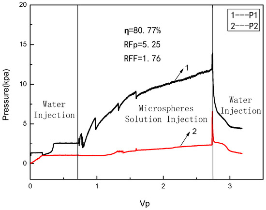
Figure 14.
Relation between pressure and injection volume (120 °C, 15 d, Cmicrospheres = 1000 mg/L, Q = 1.0 mL/min, CNaCl = 10,000 mg/L, K = 0.90 μm2).
3.6. Profile Control Characteristics of AM/PF Polymer Microspheres
The oil displacement effect of polymer microspheres was evaluated by using a three-layer heterogeneous core with crude oil saturation of 56.41%. The results are shown in Figure 15. It can be seen from Figure 15 that in the early stage of water flooding, the injected fluid mainly enters the high-permeability layer. After most of the crude oil is displaced, a large amount is still left in the middle- and low-permeability layers, and the water flooding recovery rate is only 47.71%, which is consistent with the actual development effect of the oilfield. In the stage of polymer microsphere injection, the injection pressure gradually increases with the increase in injection volume, the water content decreases, and the recovery rate increases. This is because the injection of polymer microspheres makes a part of the residual crude oil in the high-permeability layer be driven out again, and the microspheres absorb water and expand, which has a certain plugging effect on the high-permeability layer, resulting in increasing injection pressure. In the subsequent water flooding stage, the injection pressure continues to rise and become stable; the fluctuation of water content increases; and the recovery rate continues to increase until it no longer changes. The polymer microspheres are fully absorbed and expanded in the subsequent water flooding stage, and they migrate to the deep area of the core with the injected fluid, which produces a stronger plugging effect on the high-permeability layer so that the subsequent injected fluid enters more into the middle- and low-permeability layers. The sweep volume of the fluid is increased so that more residual crude oil in the middle- and low-permeability layers is displaced and the recovery rate is further improved. When the subsequent water flooding reaches 4.5 PV, the final recovery rate of the core reaches 61.00%, which is 13.29% higher than that of water flooding, and the effect of improving oil recovery is remarkable.
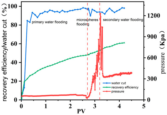
Figure 15.
Variation in core water cut, recovery efficiency, and injection pressure with injection volume (120 °C, 10 d, Cmicrospheres = 1000 mg/L, Q = 1.0 mL/min, CNaCl = 10,000 mg/L, K = 0.50, 1.50, 2.50 μm2).
4. Conclusions
The particle size of AM/PF polymer microspheres is primarily distributed within the range of 15 to 40 μm. The particle size of AM/PF polymer microspheres can increase up to five times after swelling in water at elevated temperatures. As swelling time increases, the particle size of the microspheres first increases and then stabilizes. As the temperature rises, the size of the microspheres also increases. As swelling time and temperature increase, the plugging effect of the microspheres on the membrane is gradually enhanced. As the concentration of microspheres increases, their plugging ability in sand-filled pipes gradually enhances, while their migration ability diminishes. As the permeability of the sand tube increases, its migration ability also improves. Core displacement experiments demonstrate that the prepared polymer microspheres represent a heterogeneous reservoir, effectively enhancing the recovery rate following water flooding development in such reservoirs.
Author Contributions
Conceptualization, Z.Y.; methodology, Z.Y.; formal analysis, J.S. and T.W.; resources, N.L.; data curation, D.Z.; writing—original draft, D.Z.; writing—review and editing, X.L., K.H., J.Z., J.S., N.L. and T.W.; project administration, Z.Y. All authors have read and agreed to the published version of the manuscript.
Funding
This research received no external funding.
Data Availability Statement
The original contributions presented in this study are included in the article. Further inquiries can be directed to the corresponding author.
Conflicts of Interest
Authors Dexi Zhao, Xianjie Li, Ke Hu, Jian Zhang, Jincheng Shan, Ning Liu, and Tianhui Wang were employed by the company CNOOC. The remaining author declares that the research was conducted in the absence of any commercial or financial relationships that could be construed as a potential conflict of interest. The CNOOC had no role in the design of the study; in the collection, analyses, or interpretation of data; in the writing of the manuscript, or in the decision to publish the results.
References
- Wu, S.; Sun, G.; Cheng, H.; Zhao, J. Study on the reservoir parameters variation mechanism of sandstone oil reservoir with longterm water drive. Pet. Geol. Recovery Effic. 2004, 11, 9–11. [Google Scholar]
- Xiong, C.; Tang, X. Technologies of water shut-off and profile control: An overview. Pet. Explor. Dev. 2007, 34, 83–88. [Google Scholar]
- Smith, J.E. Closing the lab-field gap: A look at near-wellbore flow regimes and performance of 57 field projects. In Proceedings of the SPE/DOE Improved Oil Recovery Symposium, Tulsa, OK, USA, 17–20 April 1994. [Google Scholar]
- Smith, J.E. The transition pressure: A quick method for quantifying polyacrylamide gel strength. In Proceedings of the SPE International Symposium on Oilfield Chemistry, Houston, TX, USA, 8–10 February 1989. [Google Scholar]
- Lin, M.; Li, M.; Ji, S. Flow resistance of colloidal dispersion gel in porous media. J. Univ. Pet. 1998, 22, 93–95. [Google Scholar]
- Mack, J.C.; Smith, J.E. In-depth colloidal dispersion gels improve oil recovery efficiency. In Proceedings of the SPE/DOE Improved Oil Recovery Symposium, Tulsa, OK, USA, 17–20 April 1994. [Google Scholar]
- Fielding, R.C., Jr.; Gibbons, D.H.; Legrand, F.P. In-depth drive fluid diversion using an evolution of colloidal dispersion gels and new bulk gels: An operational case history of north rainbow ranch unit. In Proceedings of the SPE/DOE Improved Oil Recovery Symposium, Tulsa, OK, USA, 17–20 April 1994. [Google Scholar]
- Smith, J.E.; Mack, J.C.; Nicol, A.B. The Adon Road: An in-depth gel case history. In Proceedings of the SPE/DOE Improved Oil Recovery Symposium, Tulsa, OK, USA, 21–24 April 1996. [Google Scholar]
- Chang, H.L.; Sui, X.; Xiao, L.; Liu, H.; Guo, Z.; Yao, Y.; Xiao, Y.; Chen, G.; Song, K.; Mack, J.C. Successful field pilot of in-depth Colloidal Dispersion Gel (CDG) technology in Daqing Oil field. SPE Reserv. Eval. Eng. 2006, 9, 664–673. [Google Scholar] [CrossRef]
- Li, M.; Wang, A.; Yu, X.; Zhao, Z.; Lin, M. The flowing diversion mechanism of linked polymer solution. Acta Pet. Sin. Pet. Process. Sect. 2007, 23, 31–35. [Google Scholar]
- Xu, G.L.; Lin, M.Q.; Li, M.Y. Plugging performance of linked polymer solutions. J. Univ. Pet. 2001, 25, 85–87. [Google Scholar]
- Lin, M.; Zhao, Z.; Li, M.; Dong, Z.; Peng, B. The effect of surface wettability of porous media on the plugging properties of LPS. Acta Pet. Sin. Pet. Process. Sect. 2009, 20, 91–95. [Google Scholar]
- Li, M.Y.; Lin, M.Q.; Zheng, X.Y.; Wu, Z.L. Linked polymer solution as in-depth permeability control agent: Laboratory study and field test. Oilfield Chem. 2000, 17, 144–147. [Google Scholar]
- Hua, Z.; Lin, M.; Dong, Z.; Li, M.; Zhang, G.; Yang, J. Study of deep profile control and oil displacement technologies with nanoscale polymer microspheres. J. Colloid Interface Sci. 2014, 424, 67–74. [Google Scholar] [CrossRef] [PubMed]
- Pritchett, J.; Frampton, H.; Brinkman, J.; Cheung, S.; Morgan, J.; Chang, K.T.; Williams, D.; Goodgame, J. Field Application of a New In-Depth Waterflood Conformance Improvement Tool. In Proceedings of the SPE International Improved Oil Recovery Conference in Asia Pacific, Kuala Lumpur, Malaysia, 20–21 October 2003. [Google Scholar]
- Huang, X.; Li, X.; Jin, W.; Nan, J.; Hui, P. Research on deep profile controlling and flooding technology with high temperature and salt resistance microspheres in Wenzhong Oilfield. Oil Drill. Prod. Technol. 2013, 35, 100–103. [Google Scholar]
- Zhao, Q.; Lin, M.; Dang, S.; Hua, Z. Acrylamide/2-Acrylamido-2-methylpropanesulfonic acid/1-Vinyl-2-pyrrolidinone Terpolymeric Microspheres by Orthogonal Experiments. Asian J. Chem. 2014, 26, 5615–5618. [Google Scholar] [CrossRef]
- Lin, M.; Zhao, Q.; Dang, S.; Wang, Y.; Wang, Y.; Wang, X. Preparation and properties of terpolymeric microspheres for deep profile control in oilfields. Mater. Res. Innov. 2015, 19, 574–579. [Google Scholar] [CrossRef]
- Qu, W.C.; Song, K.P. Preparation and Characterization of Superfine Polymer Microspheres in Low Permeability Reservoir. Oilfield Chem. 2015, 32, 198–202. [Google Scholar]
- Yang, C.C.; Yue, X.A.; Zhou, D.Y.; He, J.; Zhao, J.; Zhou, J.; Li, C. Performance Evaluation of Polymer Microsphere with High Temperature Resistance and High Salinity Tolerance. Oilfield Chem. 2016, 33, 254–260. [Google Scholar]
- Yang, C.; Yue, X.; Li, C.; Xu, R.; Wei, J. Combining carbon dioxide and strong emulsifier in-depth huff and puff with DCA microsphere plugging in horizontal wells of high temperature and high-salinity reservoirs. J. Nat. Gas Sci. Eng. 2017, 42, 56–68. [Google Scholar] [CrossRef]
- Lin, M.; Dong, Z.; Han, F.; Li, M.; Wu, Z. Study on the size of the LPC with nuclepore film. Membr. Sci. Tech. 2005, 25, 42–45. [Google Scholar]
- Wang, Z.; Lin, M.; Xiang, Y.; Zeng, T.; Dong, Z.; Zhang, J.; Yang, Z. Zr-Induced Thermostable Polymeric Nanospheres with Double-Cross-Linked Architectures for Oil Recovery. Energy Fuels 2019, 33, 10356–10364. [Google Scholar] [CrossRef]
Disclaimer/Publisher’s Note: The statements, opinions and data contained in all publications are solely those of the individual author(s) and contributor(s) and not of MDPI and/or the editor(s). MDPI and/or the editor(s) disclaim responsibility for any injury to people or property resulting from any ideas, methods, instructions or products referred to in the content. |
© 2025 by the authors. Licensee MDPI, Basel, Switzerland. This article is an open access article distributed under the terms and conditions of the Creative Commons Attribution (CC BY) license (https://creativecommons.org/licenses/by/4.0/).