Abstract
In the context of the “carbon peaking and carbon neutrality” era, China’s steel industry, as one of the pillars of the national economy, must accelerate the exploration and adoption of innovative production processes to effectively reduce its carbon footprint. The numerical simulation of hydrogen-based shaft furnaces is an important method for studying the internal characteristics of steelmaking processes. Its objective is to set reasonable furnace parameters to significantly enhance production efficiency and environmental friendliness, ensuring that sustainability and economic benefits coexist in the steel manufacturing process. In order to develop a new shaft furnace, which simplifies the cooling parts, the mathematical model was used to conduct a numerical simulation analysis of hydrogen-based shaft furnaces. The Discrete Element Method (DEM) was employed to focus on the stress and wear behavior of internal components within the hydrogen-based shaft furnace. The results indicated that during the charging of iron ore pellets, the outlet area experienced friction and compression from Direct Reduced Iron (DRI), resulting in a maximum stress of 47,422.1 Pa at the output section. The stresses on the loosening roller were locally concentrated due to its clockwise rotational motion, with a maximum shear stress of 219,896.1 Pa. By applying the Archard wear theory and the moving bed model, the theoretical wear degrees of the refractory materials in the reduction section and the steel shell in the cooling section were obtained; the monthly wear rate of the loosening roller was approximately 0.601 mm. Reasonably setting the parameters and feeding speed of the hydrogen-based shaft furnace can optimize the force and wear conditions of internal components, achieving optimal operating conditions. This provides a reference for factories to effectively extend the service life of hydrogen-based shaft furnaces and offers reasonable suggestions for the future industrial application of hydrogen metallurgy.
1. Introduction
Given that the CO2 emissions of China’s steel industry account for about 15% of the country’s total and China is facing the urgent tasks of “carbon peak” and “carbon neutrality”, the industry urgently needs to address these major challenges [1]. To achieve “dual carbon” goals and green development, China’s steel industry must accelerate the exploration of innovative processes, promote the application of low-carbon technologies, facilitate industrial transformation, reduce carbon emissions, and move towards the path of green low-carbon manufacturing and high-quality environmental protection [2,3,4,5]. Introducing hydrogen energy in the metallurgical field is an environmentally friendly and efficient production technology, and an important way to reduce carbon emissions in China’s steel industry [6,7,8,9,10]. Replacing carbon with hydrogen has become one of the effective strategies for steel companies to achieve China’s “dual carbon” goals. The use of hydrogen for iron smelting can significantly reduce greenhouse gas emissions and reduce the pollution introduced by carbon reducing agents from the source. European, Swedish, Japanese, and Chinese companies are gradually shifting towards the green production model of hydrogen reduction metallurgy [11,12,13,14,15].
The hydrogen-based shaft furnace direct reduction process, with its advantages of low energy consumption, low environmental load, and high product quality, has become the world’s largest direct reduction process in terms of production scale [16]. On this basis, hydrogen-based shaft furnaces, as a low-carbon and efficient ironmaking technology, have become a key research and development hotspot [17,18,19,20,21]. A major bottleneck in the development of hydrogen-based shaft furnaces is the severe wear and tear of internal components caused by ore pellets, resulting in frequent maintenance and increased production costs. Therefore, in the production process of Direct Reduced Iron (DRI), hydrogen-based shaft furnaces are often not the preferred option. At present, there is little research on the wear during the operation of hydrogen-based shaft furnaces both domestically and internationally, and the use of Rocky simulation is even rarer. To fully leverage the advantages of direct reduction in hydrogen-based shaft furnaces, an in-depth exploration of the interaction between their components and pellets during the operation is expected to improve production efficiency, reduce costs, and enable them to compete effectively with blast furnaces.
DEM is a numerical simulation method used to simulate the mechanical behavior of discontinuous media, and is applied in the field of metallurgy to study the interaction between particle beds and metallurgical furnace walls. For example, Zhang H et al. [22] used DEM simulation to analyze the process of a single large particle with a diameter of 6 mm colliding with a wall. They studied the effects of collision velocity, collision angle, and shear modulus on the collision process and maximum normal contact force by using the Hertz Mindlin non-slip contact model. Xu Q et al. [23] extended the Member Discrete Element Method (MDEM) to analyze the contact and collision behavior of structures. The proposed MDEM can effectively simulate the contact behavior between structures and rigid boundaries, as well as the contact and collision response of structures. Huang L J et al. [24] used DEM and the Hertz Mindlin bonding contact model to study and analyze the effects of relative velocity and different particle size ratios on the particle fragmentation behavior. Kuang D et al. [25] used the Random Field Theory Discrete Element Method (RFT-DEM) model to simulate and analyze the complex behavior of granular materials during single particle crushing, providing a powerful framework. You Y et al. [26] introduced Areal Gas Distribution (AGD) technology based on DEM research to study the material movement behavior in COREX shaft furnaces. Based on the above research, it is feasible to use the DEM method to study the interaction between pellets and internal components of hydrogen-based shaft furnaces [27,28,29]. The current research mostly focuses on the macroscopic motion of furnace materials under steady-state production in shaft furnaces, while there is little research on the stress and wear effects of nodular ore/DRI in hydrogen-based shaft furnaces on the refractory materials in the reduction section, steel shells in the cooling section, and loose rollers.
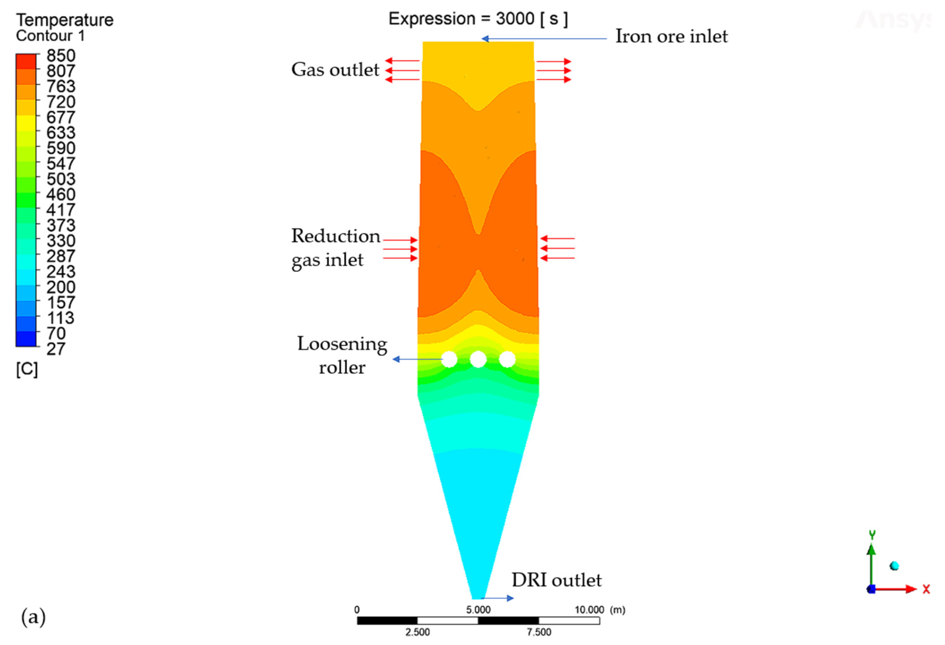
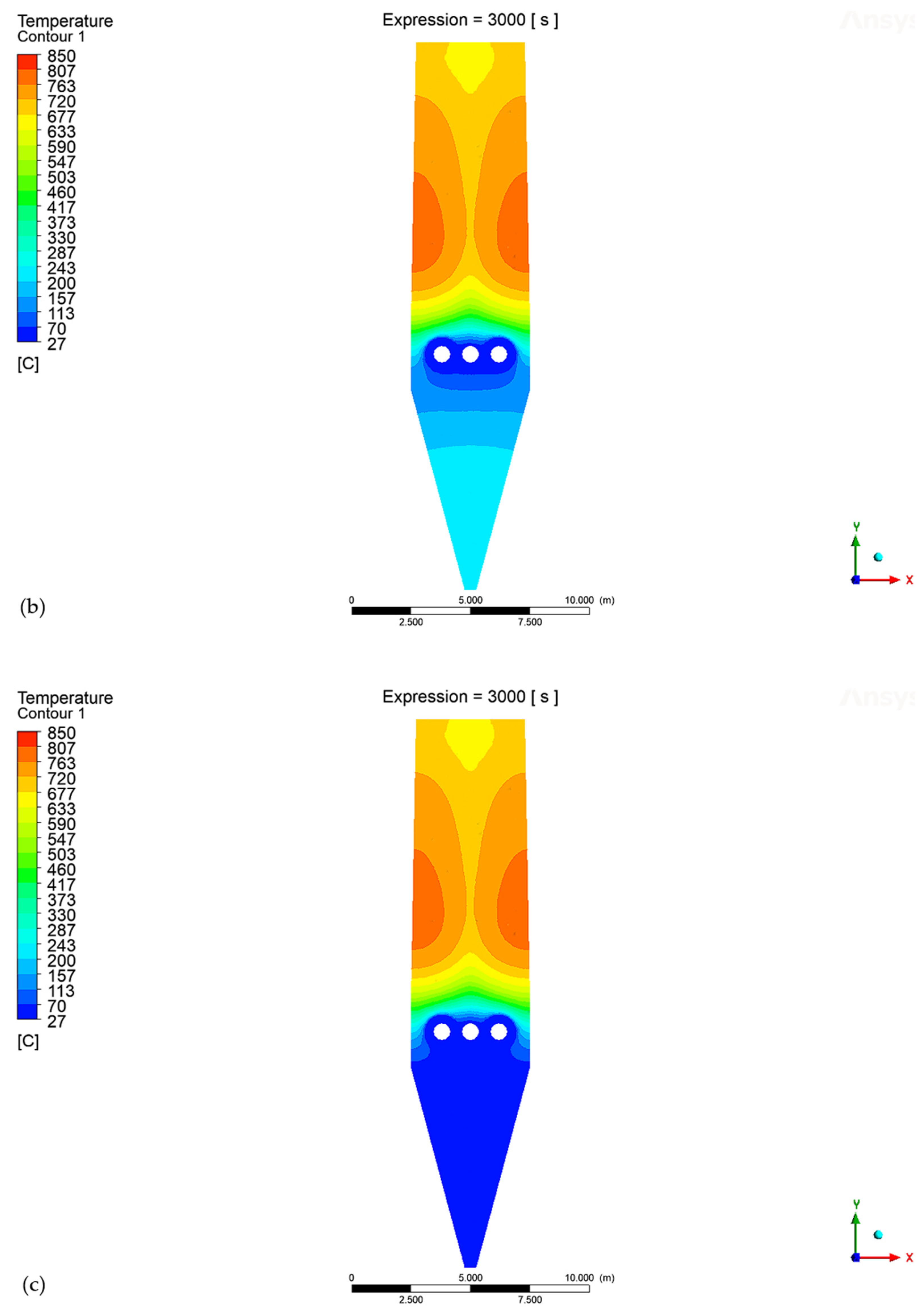
As the cooling part of the current shaft furnace is complex and needs to be maintained frequently, our team has developed a new combining loosening roller, which can cool the DRI and continuously loosen the cooled DRI at the same time. The newly developed shaft furnace simplified the lower part design as it did not need the complex parts for cooling gas input and output. Figure 1 shows the temperature cloud map inside a hydrogen-based shaft furnace. As shown in Figure 1a, the high-temperature reducing gas enters the hydrogen-based vertical furnace in the middle and undergoes a reduction reaction with the ambient temperature iron ore pellets added at the top in a “convection moving bed” manner. The iron ore pellets ultimately form the DRI, which is cooled and discharged through the furnace bottom. Its advantages include: (1) Simplifying the design of the reduction section, eliminating a large number of turning sections in the internal configuration, and designing it as a cylindrical section with a reverse taper, which is convenient for bricklaying and facilitates the downward movement of the pellets. (2) Cancelling the complex cooling equipment and using three loose cooling rollers in conjunction with the cooling wall of the cooling section as an alternative cooling device to increase the lifespan of the cooling section and reduce the maintenance workload. In order to study the wear condition of the inner part of the newly developed shaft furnace, this article uses DEM + Archard model to deeply explore the stress and wear effects of nodular ore/DRI and internal components of hydrogen-based shaft furnaces, covering refractory materials in the reduction section, steel furnace walls in the cooling section, and loose rollers. The stress state and wear behavior are analyzed, providing theoretical and scientific basis for the design and operation of hydrogen-based shaft furnaces and filling the research gap in this field.


Figure 1.
The temperature cloud map inside the hydrogen-based shaft furnace shows (a) the absence of the cooling effect, (b) the cooling effect with only the loosening roller added, and (c) the loosening roller with the cooling effect and the addition of cooling plates in the cooling section.
2. Discrete Element Method (DEM) Model
The DEM model is based on Newton’s second law and the Lagrangian coordinate system and is used to calculate the interaction between particles and particles/walls in order to explore the material motion behavior and the stress conditions of the furnace wall [30,31,32]. Based on the Hertz contact theory and Mindlin’s non-slip model, the motion of pellets in the furnace, the contact forces between pellets, between pellets and the furnace body, and between pellets and the fluid, as well as the wear condition, were simulated and analyzed in the DEM model. Among them, the interaction force between the pellets can be decomposed into two components at the contact point: pressure along the normal direction of the contact surface (normal force) and friction along the tangent direction of the contact surface (tangential force) [33]. The forces include tangential force, torque, and normal force, which enable the particles to move horizontally and rotate. The governing equation is as follows [34]:
In the formula, is the mass of particle , kg; is the translational velocity of particle , m/s; is time, s; is the moment of inertia of particle , kg·m2; is the number of particles in contact with particle ; is the normal contact force between particles and , N; is the normal damping force between particles and , N; is the tangential contact force between particles and , N; is the tangential damping force between particles and , N; is gravity, N; is the moment of inertia of particle , m/s; is the rotational speed of particle , rad/s; is the tangential force and torque acting between particles and , N·m; is the rolling friction torque between particles and , N·m. Additionally, and are coefficients, is the radius of particle , is the normal Hertz contact stiffness constant of the particle, is the normal deformation of the particle, is the normal damping coefficient, is the normal relative velocity at the contact point between particles and , is the tangential Hertz contact stiffness constant of the particle, is the tangential deformation of the particle, is the tangential damping coefficient, is the tangential relative velocity at the contact point between particles and .
Based on the Archard wear model [35,36,37,38,39], the friction and collision between particles and furnace walls during particle falling were simulated and calculated, including various types of wear such as slight wear, adhesive wear, abrasive wear, and fatigue wear [40,41]. According to the Archard wear model theory, its control equation is shown in Formula (19):
In the formula, is the wear volume, mm3; is the normal positive pressure, N; is the sliding distance, mm; is the hardness of the material; is the wear coefficient.
3. Model Parameters and Simulation Solution
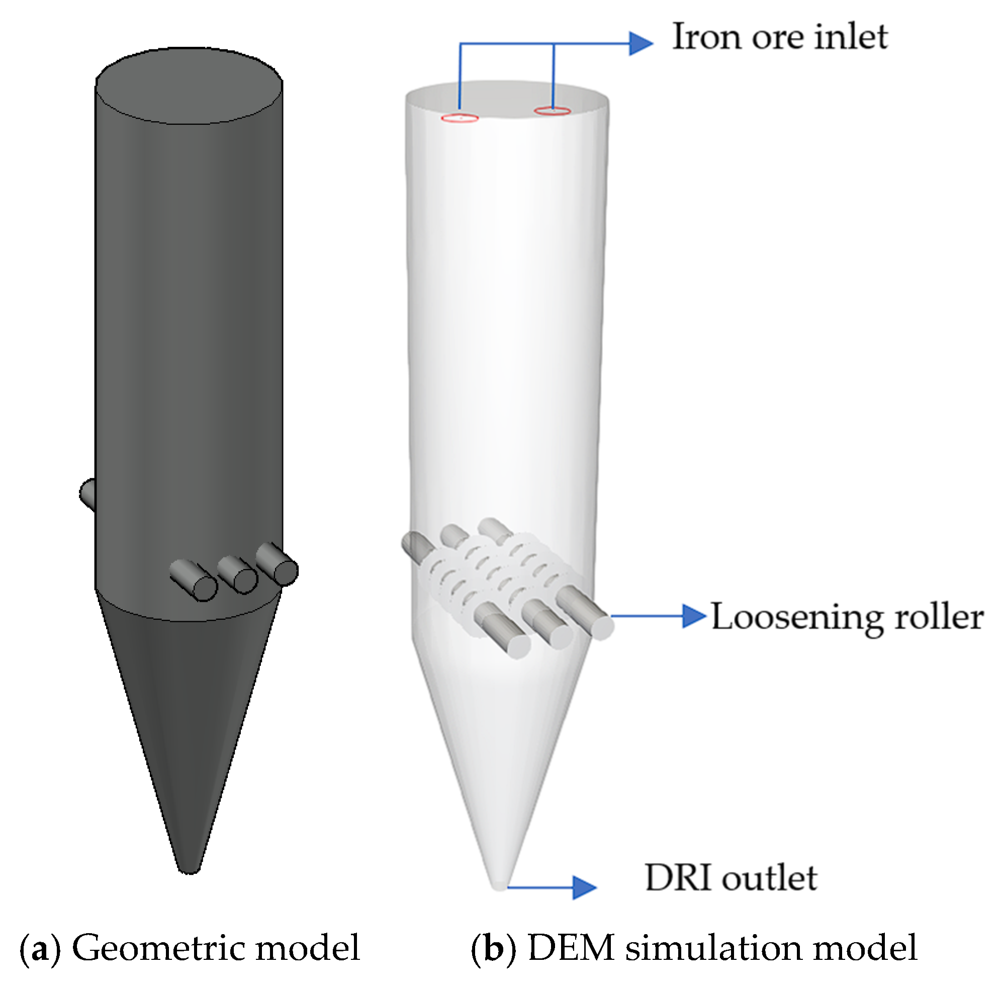
The geometric model established for the newly developed hydrogen-based shaft furnace is shown in Figure 2, in which the complex cooling gas input and output components are replaced by the combining loosening rollers and cooling plates in the cooling section. The cooling section of the traditional MIDREX furnace is a very complex process stage, in which the cooling gas is input into the cooling section by a compressor and passes through a loosening roller. The loosening roller is connected to the cooling gas collection hood, distributor, washer, and dryer of the cooling section to cool the DRI. This study designs a new hydrogen-based shaft furnace, in which the cooling section simplifies the structure of the loosening roller, ensures its cooling capacity, and can smoothly lower the DRI. In order to save computing resources and simplify the construction of the cooling section of the hydrogen-based shaft furnace, a simplified version of the hydrogen-based shaft furnace model was designed. In order to save computing resources and simplify the structure of the cooling section of the hydrogen-based shaft furnace, a simple hydrogen-based shaft furnace shell with an upper cylindrical body and a lower rounded platform was designed during the CAD modeling process. Three cylindrical bodies with fan blades were added as loosening rollers in the transition section, with the fan blades staggered and spaced at the same interval. Then, the Ansys Rocky 22.1.0 simulation software was imported to generate a hydrogen-based shaft furnace model, add feeding and discharging ports, set the feeding speed, loosen the roller speed and other parameters. As only the dynamic wear effect on the hydrogen-based shaft furnace is considered, other thermodynamic influence parameters such as temperature are not set. The particle motion process is simulated through the DEM model provided by the simulation software. In order to accelerate the simulation process, optimize resource utilization, reduce computational burden, and improve overall computational efficiency, the following assumptions were made for hydrogen-based shaft furnaces:
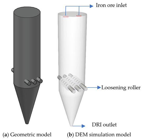
Figure 2.
Hydrogen-based shaft furnace model. (a) Hydrogen-based shaft furnace model drawn for the CAD 47.0.0 software. (b) Hydrogen-based shaft furnace model established for the Ansys Rocky 22.1.0 simulation software.
- (1)
- The gas flow inside the hydrogen-based shaft furnace is in a steady state;
- (2)
- Each iron ore pellet has the same size;
- (3)
- Only consider the wear and tear of the shaft furnace wall caused by the ore pellet, without taking into account the deformation of the ore pellet;
- (4)
- Only consider the impact of ball ore movement on the erosion and wear of furnace walls and linings, ignoring the influence of temperature;
- (5)
- The loose roller has its own cooling effect and can operate normally.
3.1. Model Parameter
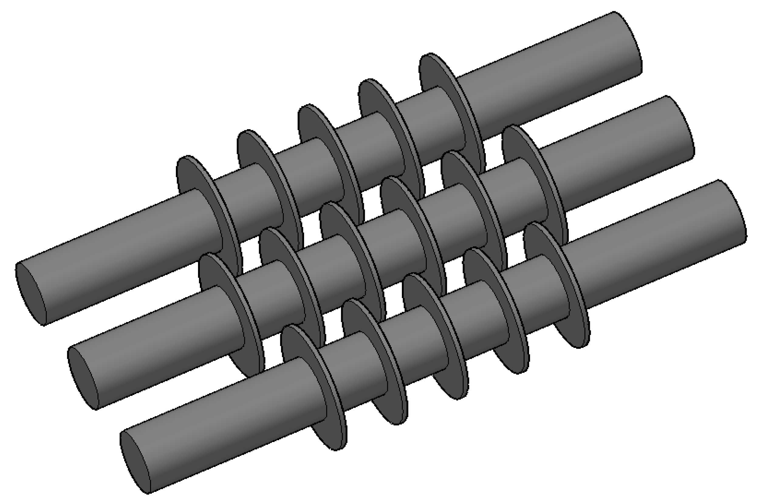
The main parameters of the hydrogen-based shaft furnace are a total height of 23 m and an upper diameter of 5 m; the outer shell of the furnace body is made of steel material. In the hydrogen-based shaft furnace, it is necessary to transport the ore pellet and crush the bonded furnace material; therefore, the loose rollers need to be installed. Loose rollers are fragile components in the hydrogen-based shaft furnace and require stress and wear analysis. The loosening roller is equipped with an inner shaft and fan blades, as shown in Figure 3. The specific parameters of the hydrogen-based shaft furnace and its loosening roller are shown in Table 1. From the table, it can be seen that the pellets are added to simulate the iron ore/DRI particles in the simulation calculation. Figure 4 shows the profile of the particles, and the specific parameters of the iron ore/DRI particles are shown in Table 2.
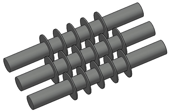
Figure 3.
Loosening rollers model. Three loose rollers are arranged in a staggered manner according to the position of the fan blades.

Table 1.
Parameters of the hydrogen-based shaft furnace body and loosening roller.
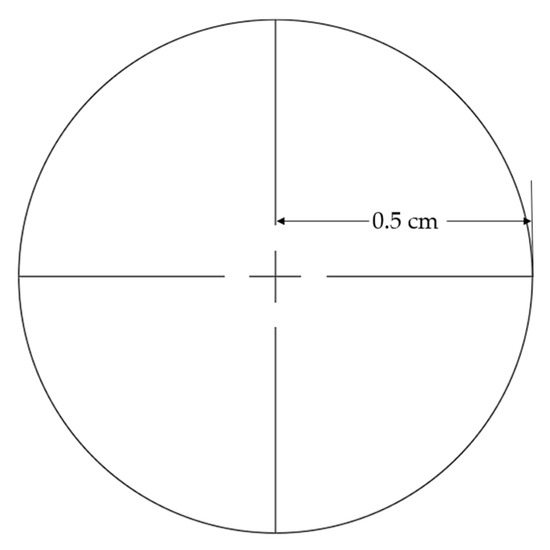
Figure 4.
Profile of iron ore/ Direct Reduced Iron (DRI) particles. The diameter of the particles is 1 cm.
Table 2.
Information on iron ore/DRI particles.
3.2. Simulated Conditions
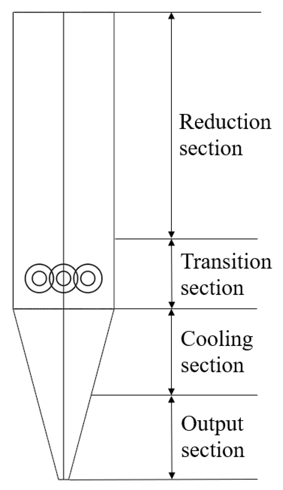
In the model setting, the collected data include wear duration, finite element analysis force, frequency, strength, normal impact velocity, sliding distance, stress, and statistics of inter-group collisions. A control group is set up in the geometric model establishment for comparison. The parameters of the pellet particles in this study are a particle size of 0.01 m and a density of 2200 kg/m3. As shown in Figure 5, the shaft furnace is divided into three stages: reduction, transition, and cooling. Given that the cooling section requires the discharge of DRI and this process affects its stress and wear on the steel shell, we conducted a segmented analysis of the furnace body below the transition section to ensure the comprehensiveness of the stress and wear research in this area. Therefore, for ease of analysis, the hydrogen-based shaft furnace is divided into an output section, a cooling section, a transition section, and a reduction section. The speed of the loosening roller in the transition section is set to 20 r/min, and iron ore pellets are uniformly added to the furnace top to observe the wear of the furnace body. The reduction section and transition section furnace walls are made of refractory materials, while the cooling section and output section are made of steel shells. The furnace charge is mainly composed of a ball-shaped ore in the reduction section, and below the transition section, it becomes DRI.

Figure 5.
Four sections in the hydrogen-based shaft furnace.
3.3. Numerical Solution
For the numerical solution calculation, the model is imported from CAD into the Ansys Rocky 22.1.0 numerical simulation software. This article uses the Boundary Collision Statistics and Particles Energy Spectra solvers in Modules to solve numerical simulations. Archard wear models are added to the furnace wall and loose rollers, and data analysis is obtained by running solver for 1 h.
4. Results and Discussion
4.1. Analysis of Stress and Wear on the Wall of Hydrogen-Based Shaft Furnace
4.1.1. Stress Analysis of Iron Ore Pellets on Furnace Wall
Due to the fact that the stress condition of the furnace wall in a hydrogen-based shaft furnace has a significant impact on the service life and maintenance frequency of the furnace lining, this article simulates and analyzes the stress condition of the furnace wall.
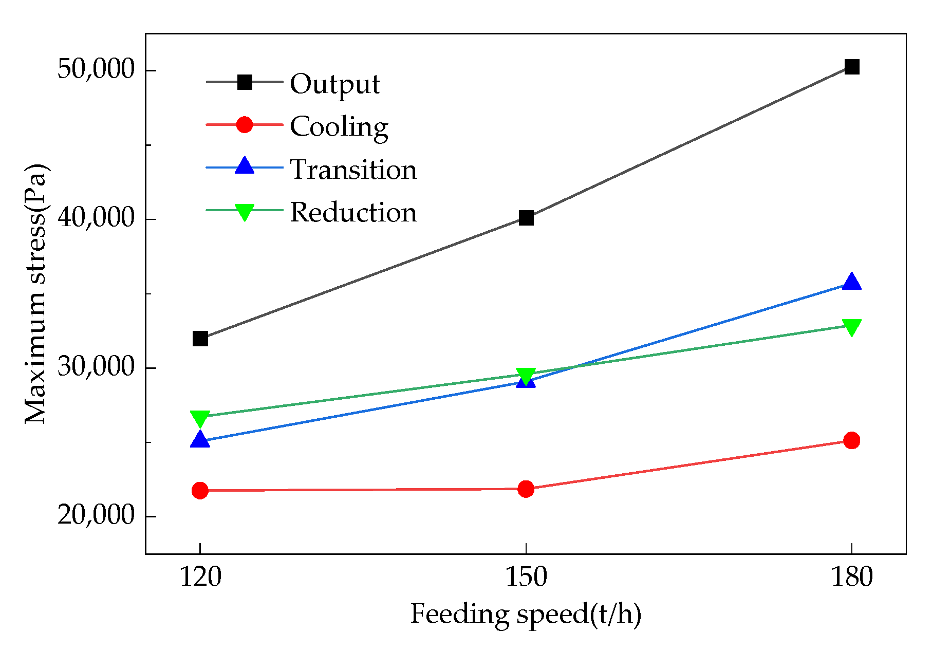
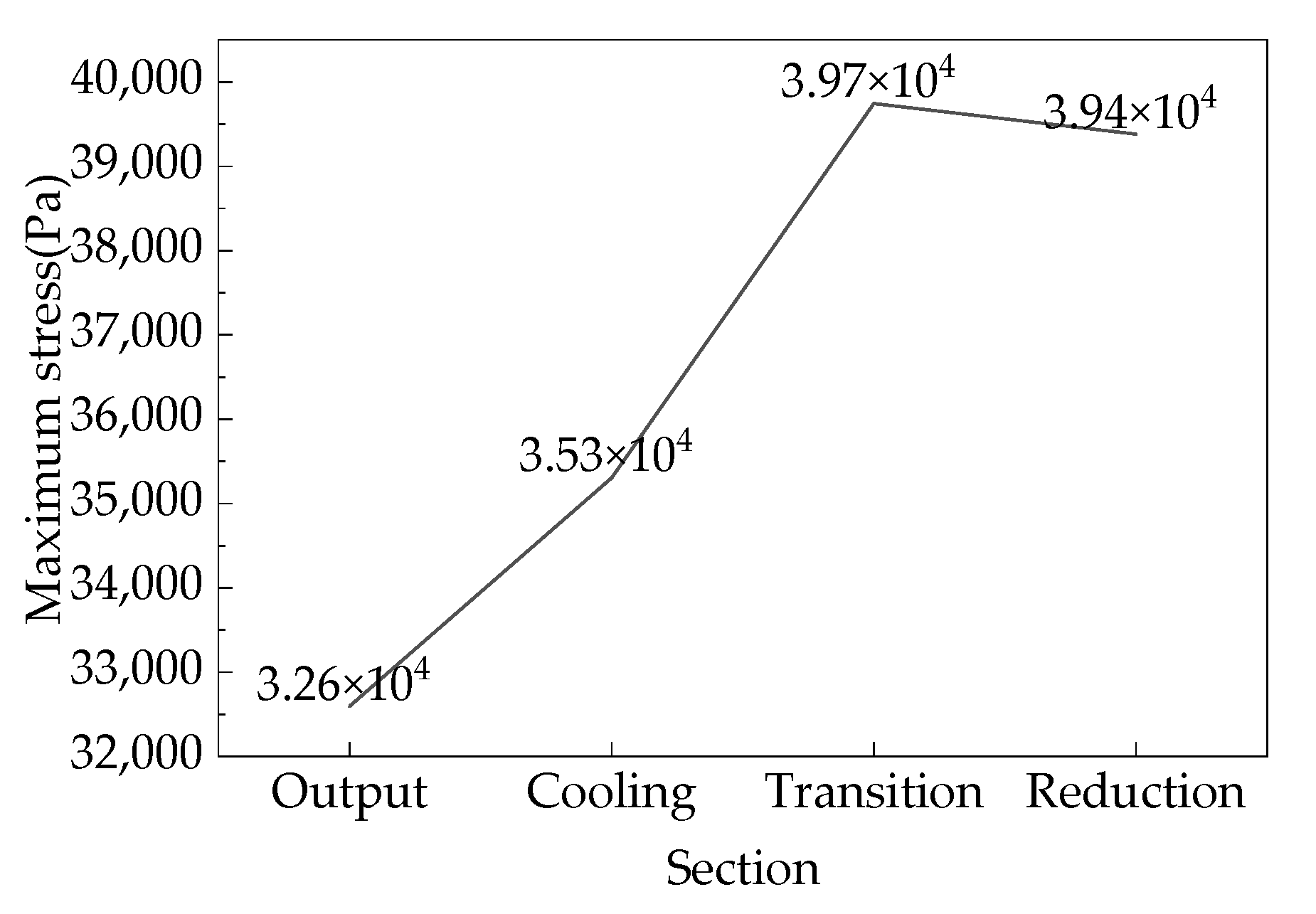
The cloud map of the normal stress distribution of each section of the furnace wall in the shaft furnace is calculated based on DEM, and the selected maximum normal stress value is called the maximum stress. The maximum stress values on each wall section of the hydrogen-based shaft furnace at different feeding rates are shown in Figure 6. From the figure, it can be seen that the furnace wall stress in the output section is the highest, with a tensile stress of 31,974 Pa when feeding at 120 t/h. Additionally, it is subjected to frictional compression due to the need to discharge DRI. The transition section is equipped with three loose rollers to adjust the discharge speed and share the weight of the furnace material. Although it is subjected to compression and wear from iron ore pellets, the stress is lower than that in the output section. The stress in the cooling section is relatively low because the loose rollers bear the weight of the upper furnace material and are not compressed by it. The stress in the reduction section is similar to that in the transition section, as the falling iron ore pellets cause compression and collision on the furnace wall.
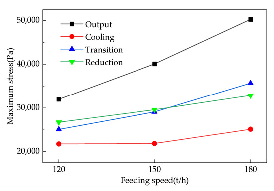
Figure 6.
Maximum stress in the hydrogen-based shaft furnace at various stages with different charging rates.
Due to the increase in feeding speed, the pellets entering the hydrogen-based shaft furnace gain greater kinetic energy, causing more severe collisions with the furnace wall at various stages and increasing the stress on the furnace wall. Therefore, increasing the feeding speed will increase the stress on each section of the furnace wall. When increasing from 120 t/h to 180 t/h, the stress growth rate in the output section is the highest, increasing from 31,974 Pa to 50,291.1 Pa; the stress in the cooling section, transition section, and reduction section also increases, respectively. Overall, for every 10 t/h increase in feeding rate, the maximum stress on the hydrogen-based shaft furnace wall increases by approximately 3052.9 Pa.
4.1.2. Wear Analysis of Furnace Wall
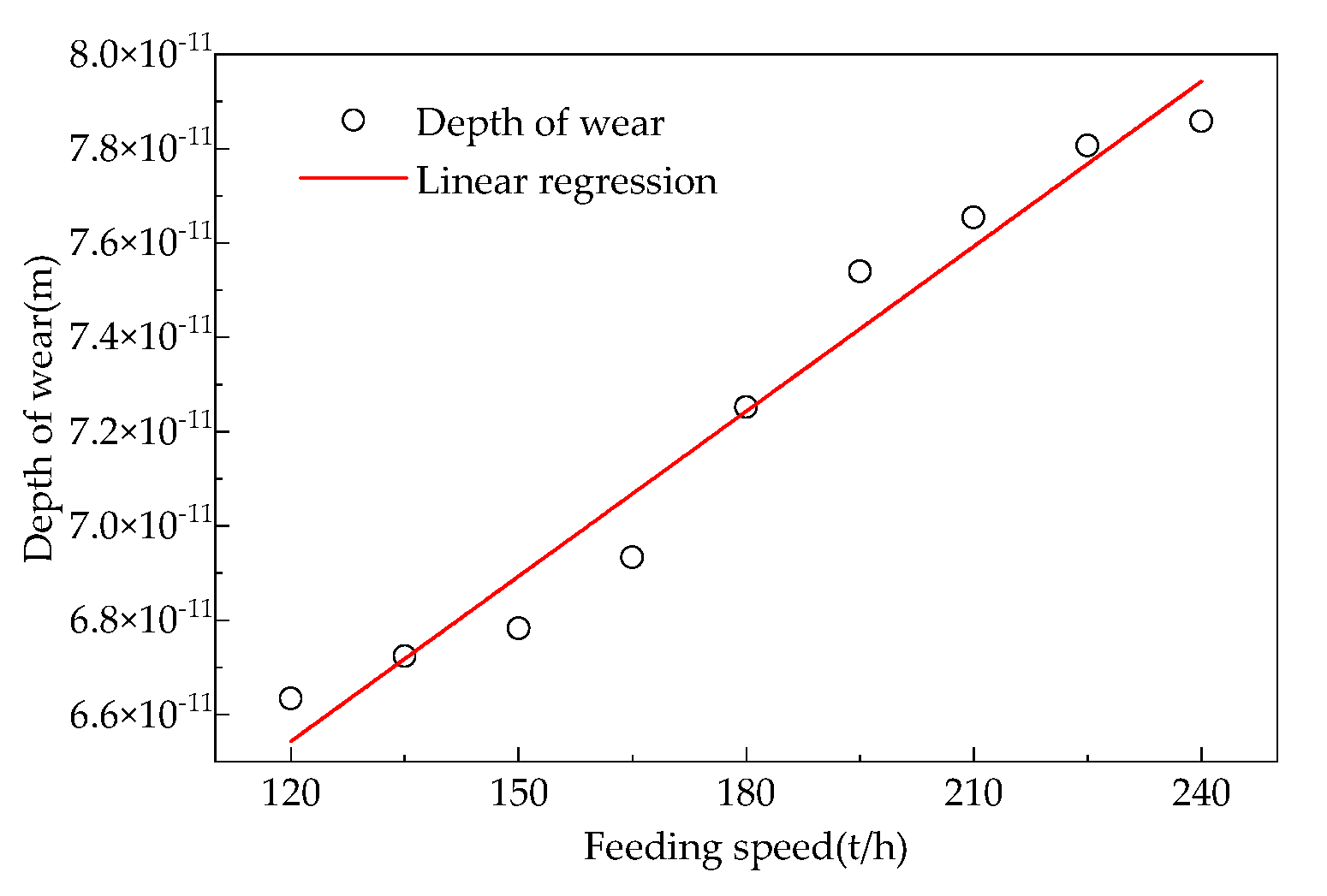
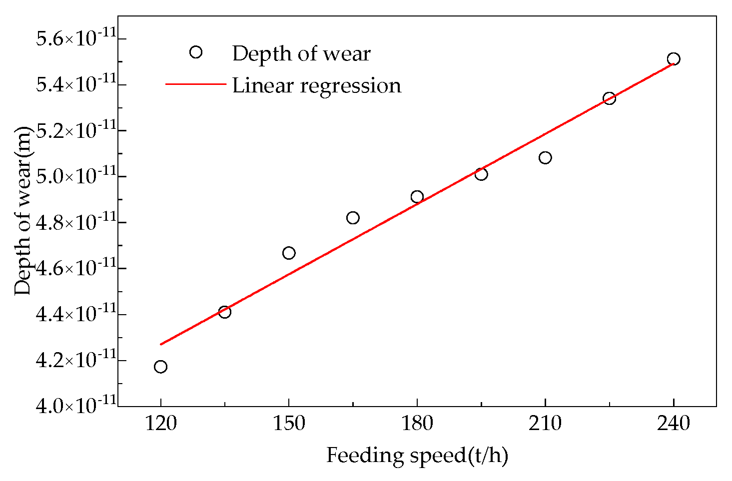
As shown in Figure 7, Figure 8, Figure 9 and Figure 10, increasing different feeding rates yields the relationship between the feeding rate and the degree of wear on the partition wall of the hydrogen-based shaft furnace.
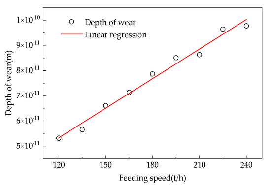
Figure 7.
Relationship between the charging rate in the output section and the degree of wear on the furnace wall.

Figure 8.
Relationship between the charging rate in the cooling section and the degree of wear on the furnace wall.
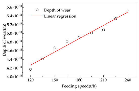
Figure 9.
Relationship between the charging rate in the transition section and the degree of wear on the furnace wall.
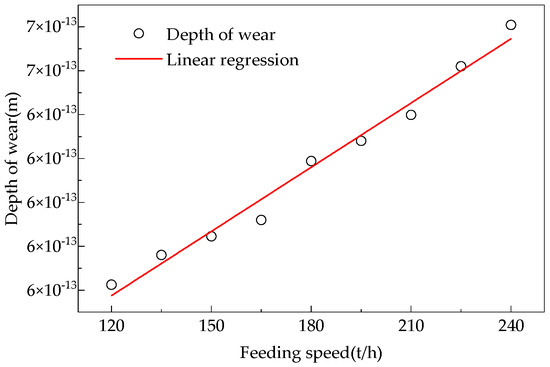
Figure 10.
Relationship between the charging rate in the reduction section and the degree of wear on the furnace wall.
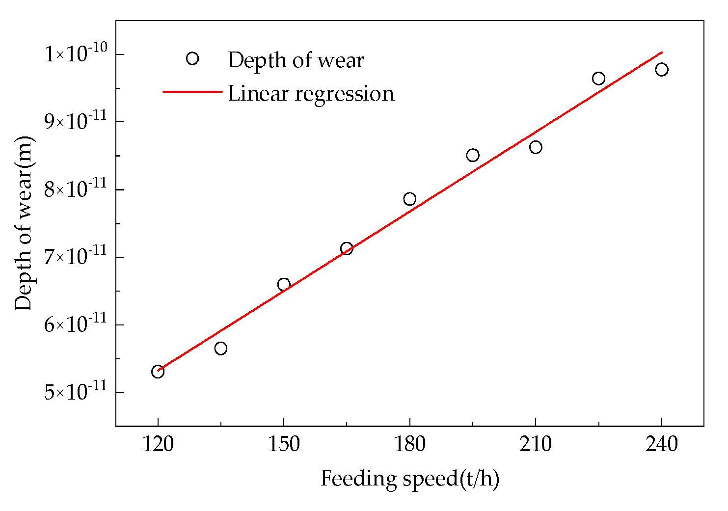
Based on the Archard wear model and the moving bed model, a simplified formula for the furnace wall wear is derived as shown in Equation (20):
In the formula, is the effective wear coefficient; is the acceleration due to gravity, m/s2; is the depth of each segment, m; is the wear depth of each section, m; is the feeding speed, t/h; is the cross-sectional area of the lower opening of each section, m2. Among them, is the section number, one is the restoration section, and two is the cooling section. Due to the presence of loose rollers in the transition section, the formula for the degree of wear is not derived here. However, there is a discharge port in the output section, which makes the force on the output section very complex. Therefore, the focus is on analyzing its force without considering wear.
Based on Equation (20), a linear regression of the data was obtained by calculating the regularity of the values. The values of and in the formula were obtained based on the slope and intercept of the regression line. The Formula (21) for the wear degree of the refractory material in the final reduction section is obtained as follows:
The Formula (22) for obtaining the degree of wear of the cooling section steel shell is obtained as follows:
From Equations (21) and (22), it can be seen that the wear coefficient of the refractory material in the reduction section is lower than that of the steel shell in the cooling section. Due to the higher hardness of the refractory material and the better shape design (cylindrical) compared to the cooling section (inverted conical), the wear of the steel shell in the cooling section is more severe.
4.2. Stress Analysis of Iron Ore Pellets
The damage of ore pellets can significantly reduce the working efficiency of hydrogen-based shaft furnaces. Therefore, this article analyzes the stress on iron ore pellets in hydrogen-based shaft furnaces.
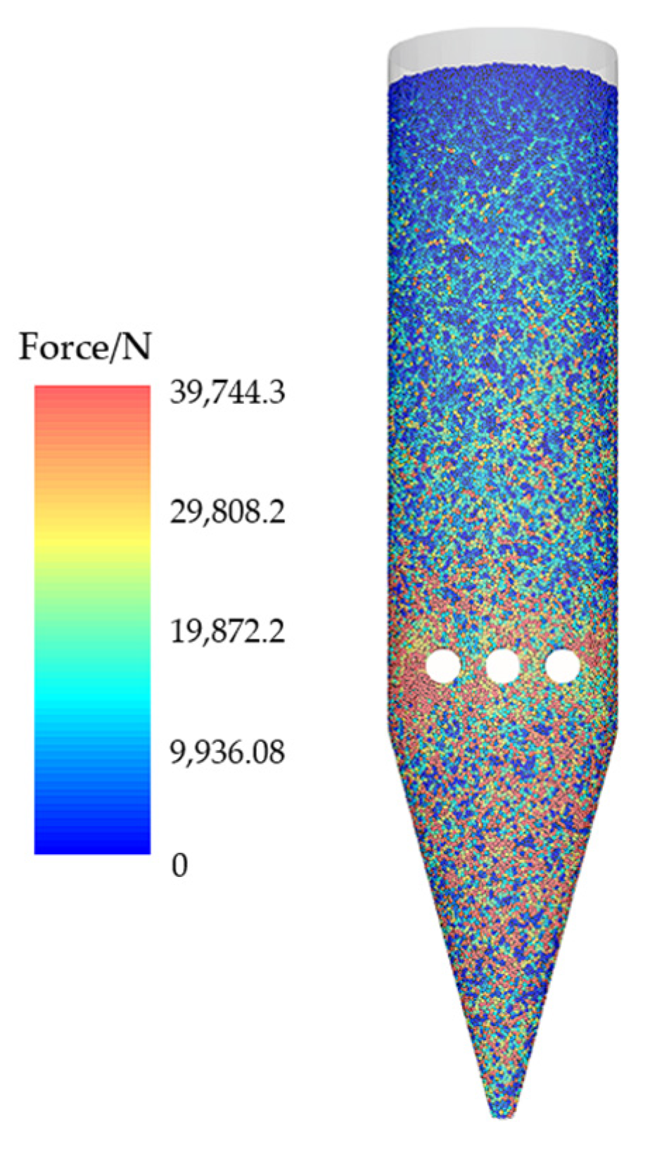
Figure 11 shows the force cloud map of iron ore pellets with a feeding rate of 150 t/h. From the figure, it can be seen that the force on the pellet particles increases with depth, which is consistent with physical principles. The loose roller compression causes the transition section to directly reduce the iron and bear the maximum stress, followed by the core pellet located 2.26 m below the material surface. The force on the DRI in the cooling section is reduced due to the loose roller support, while the force on the output section is minimized due to the output of furnace materials, as shown in Figure 12. Observing the cloud map of particle stress, it was found that high stress particles are mainly concentrated around the loose roller and above the discharge port, which is attributed to the intense movement of particles in these areas leading to strong forces between them.

Figure 11.
Force distribution of particles in the hydrogen-based shaft furnace at various stages of 150 t/h charging rate.

Figure 12.
Maximum stress on particles in the hydrogen-based shaft furnace at various stages.
4.3. Analysis of Force and Wear on Loose Rollers
4.3.1. Force Analysis of Loose Rollers
During the operation of a hydrogen-based shaft furnace, the service life of the loose rollers in the transition section determines the maintenance frequency of the furnace. Therefore, this article simulates and analyzes the stress conditions of the loose rollers.
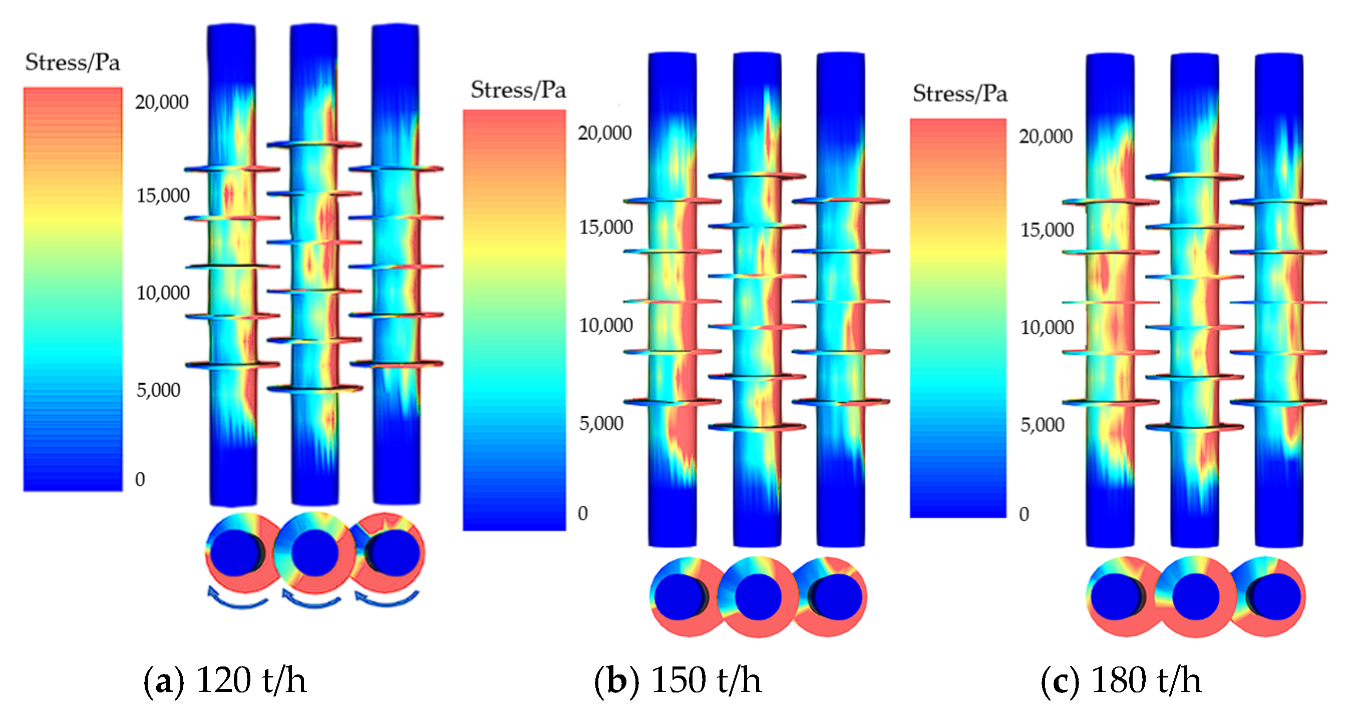
In this article, there are three loose rollers in the hydrogen-based shaft furnace. The blades on the loose rollers are arranged in a staggered manner, and the DRI entering from the reduction section of the shaft furnace is stirred and transported clockwise at a speed of 20 r/min. Figure 13 shows the force cloud map of the loose roller at 100 s of operation. Figure 12 shows that the shear stress distribution of the blades and shafts of the three loose rollers is uneven in the circumferential direction, resulting in stress concentration. This may be due to the fact that when the loose roller rotates clockwise, the upward fan blades and inner shaft parts bear greater shear stress, causing local wear and resulting in stress concentration.

Figure 13.
Stress distribution of loosening rollers with different feeding speeds.
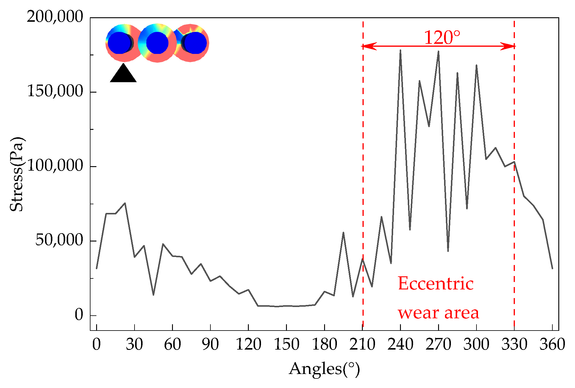
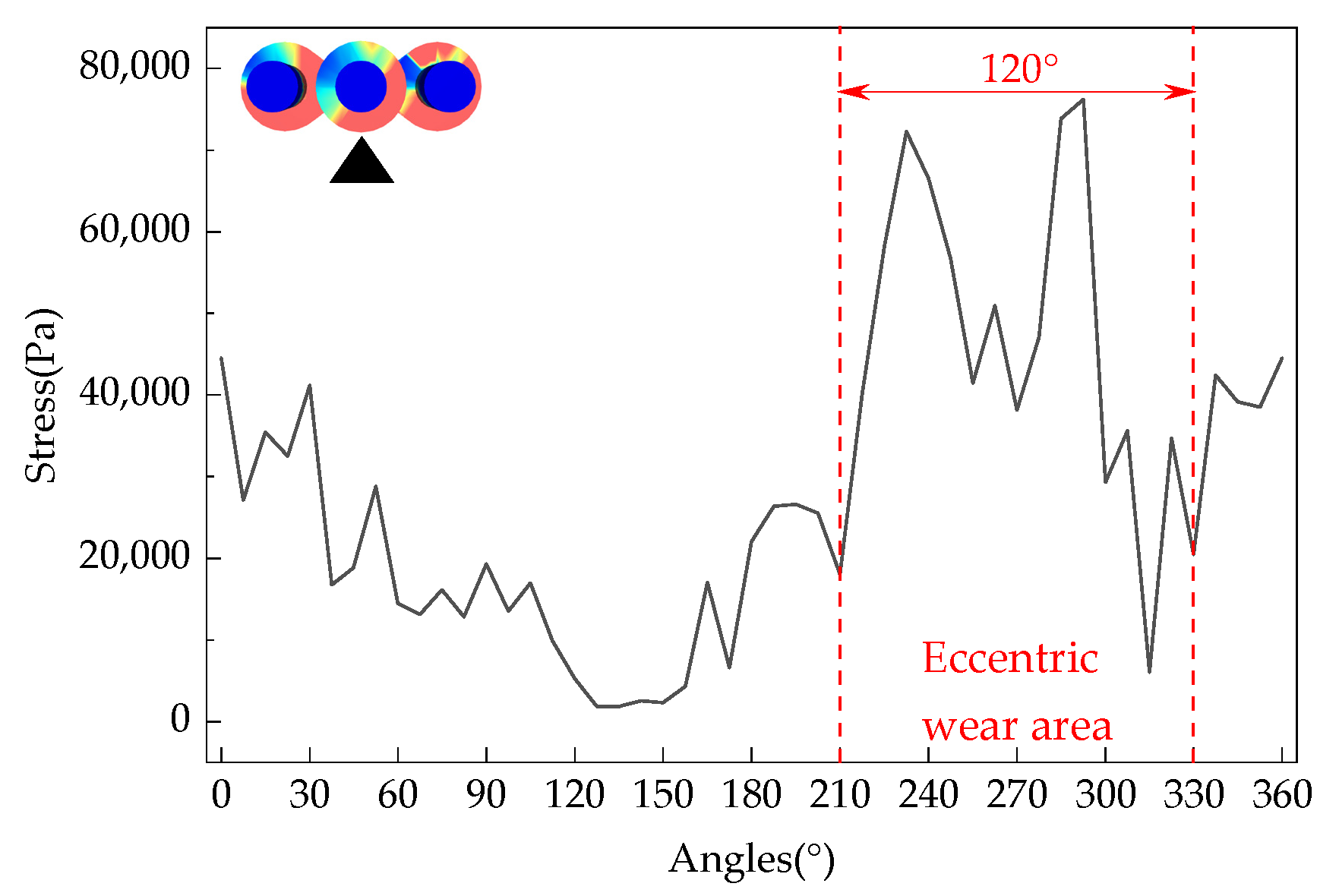
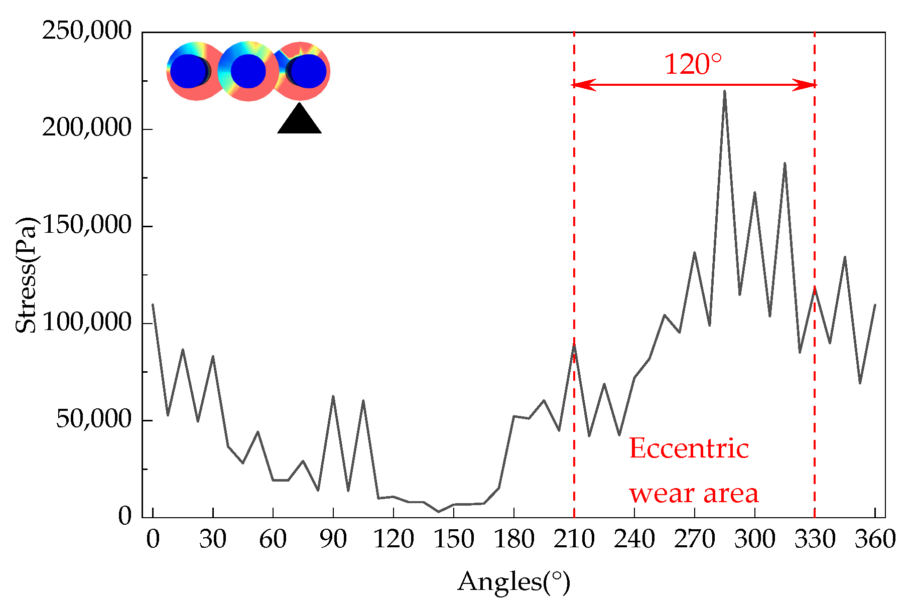
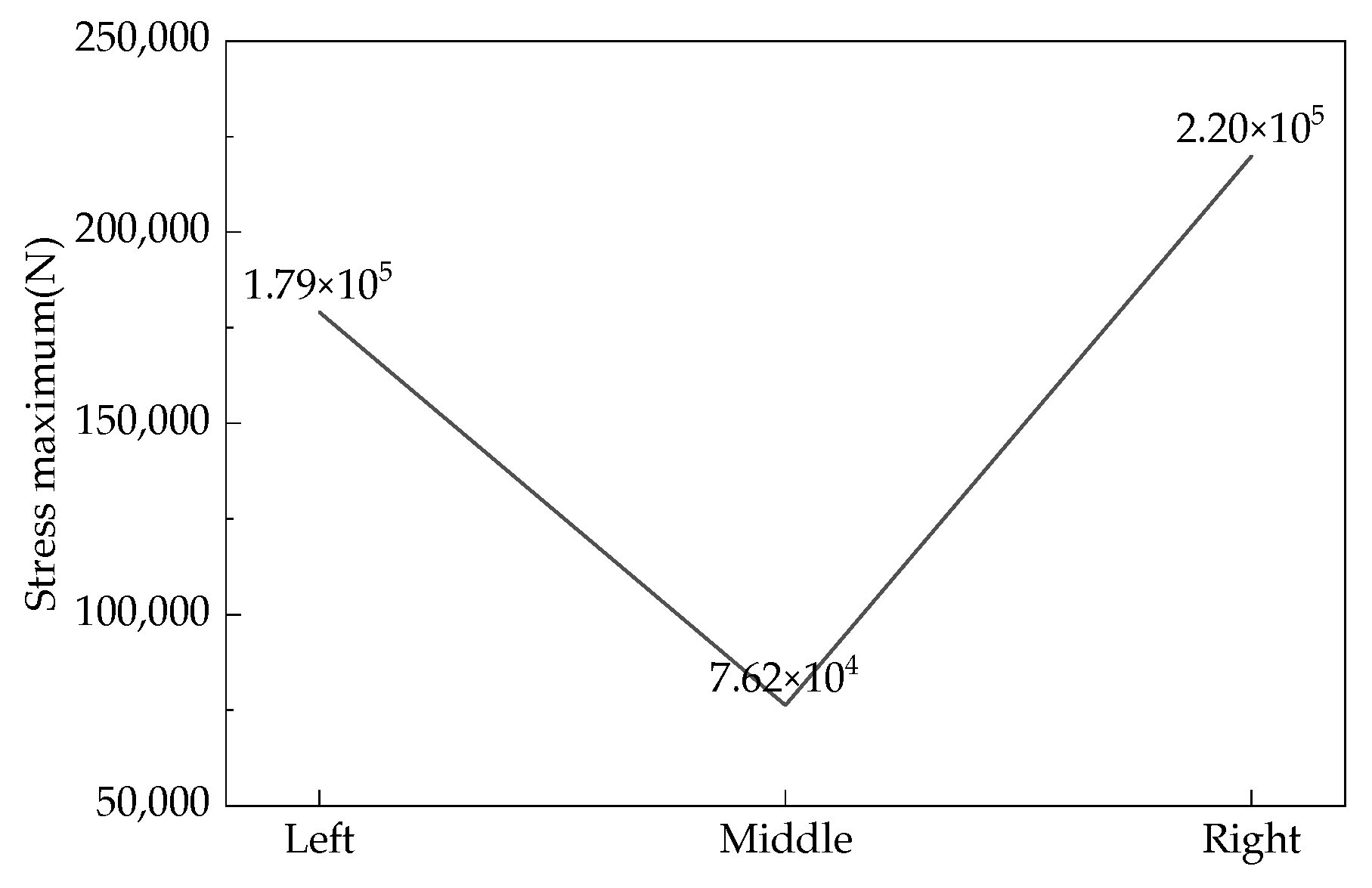
The loose roller group with a feeding speed of 150 t/h was selected as the research object. The maximum force on the fan blades of each loose roller at various angles in the circumferential direction is shown in Figure 14, Figure 15 and Figure 16. The maximum force on the fan blades of each loose roller fluctuates greatly and is the largest in the range of 240°~315°, while the force is the smallest in the range of 120°~180°. Uneven force distribution is determined by the angle of the loose rollers when the hydrogen-based shaft furnace starts operating. During the rotation process, the uneven force distribution on the loose rollers gradually leads to irregular shape changes, resulting in more severe eccentric wear due to deformation. From Figure 17, it can be seen that the maximum shear stress on the right loosening roller is 219,896.1 Pa. This is due to the clockwise rotation of the loosening roller driving nearby DRI particles to move to the right, resulting in the maximum stress on the loosening roller in the right loosening roller and local stress concentration. The reason why the middle loose roller experiences the least stress is because there is a structural difference between the middle loose roller and the outer loose roller, and more blades result in the least stress.
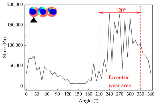
Figure 14.
Distribution of stress on the left loosening roller fan blade by DRI.
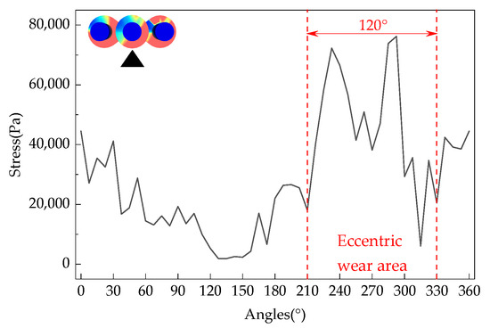
Figure 15.
Distribution of stress on the middle loosening roller fan blade by DRI.

Figure 16.
Distribution of stress on the right loosening roller fan blade by DRI.

Figure 17.
Maximum stress on each loosening roller.
4.3.2. Wear Analysis of Loose Rollers
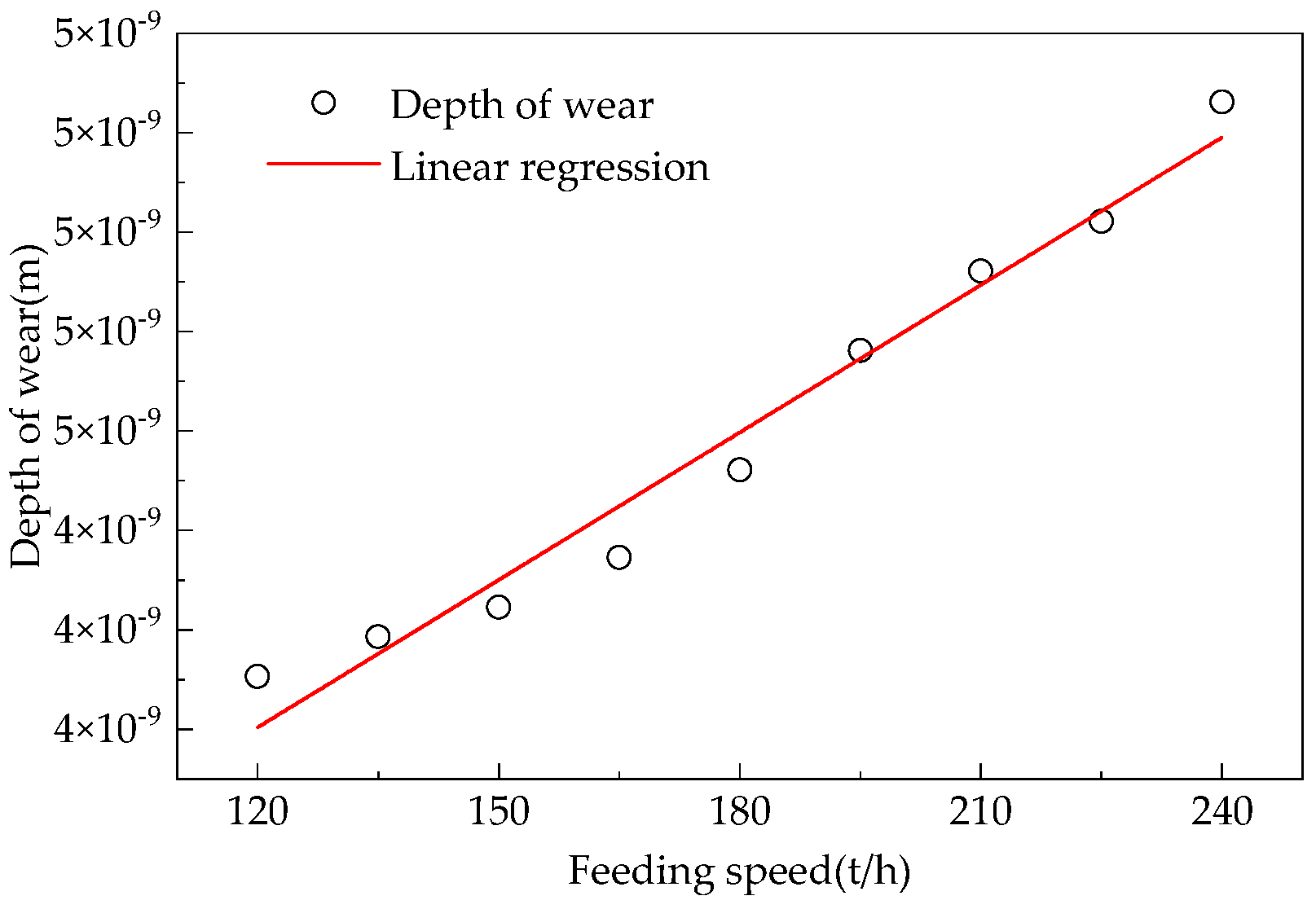
Based on the eccentric wear mechanism and Archard wear theory of the loose roller shown in Figure 14, Figure 15 and Figure 16, as well as the relationship between the feeding rate and the degree of furnace wall wear in Figure 18, the Formula (7) for the wear degree of the loose roller is obtained as follows:

Figure 18.
Relationship between loosening rollers charging speed and the degree of wear on the furnace wall.
In the formula, is the radius of the loose roller blade, m; is the curvature occupied by the loose roller eccentric wear area, °; is the depth at which the loose roller is located, m.
When adding the hydrogen-based shaft furnace to the iron ore pellet, the furnace wall, loose rollers, and iron ore pellet collide and generate stress. The friction between the loose rod and the filled iron ore pellet during rotation causes wear and erosion to the furnace wall and loose rod. Through research, it was found that the change in feeding rate has a much smaller impact on the wear of the hydrogen-based shaft furnace wall than on the wear of the loosening rod, which is a component more severely worn. Therefore, this article studied the wear of the loosening rod.
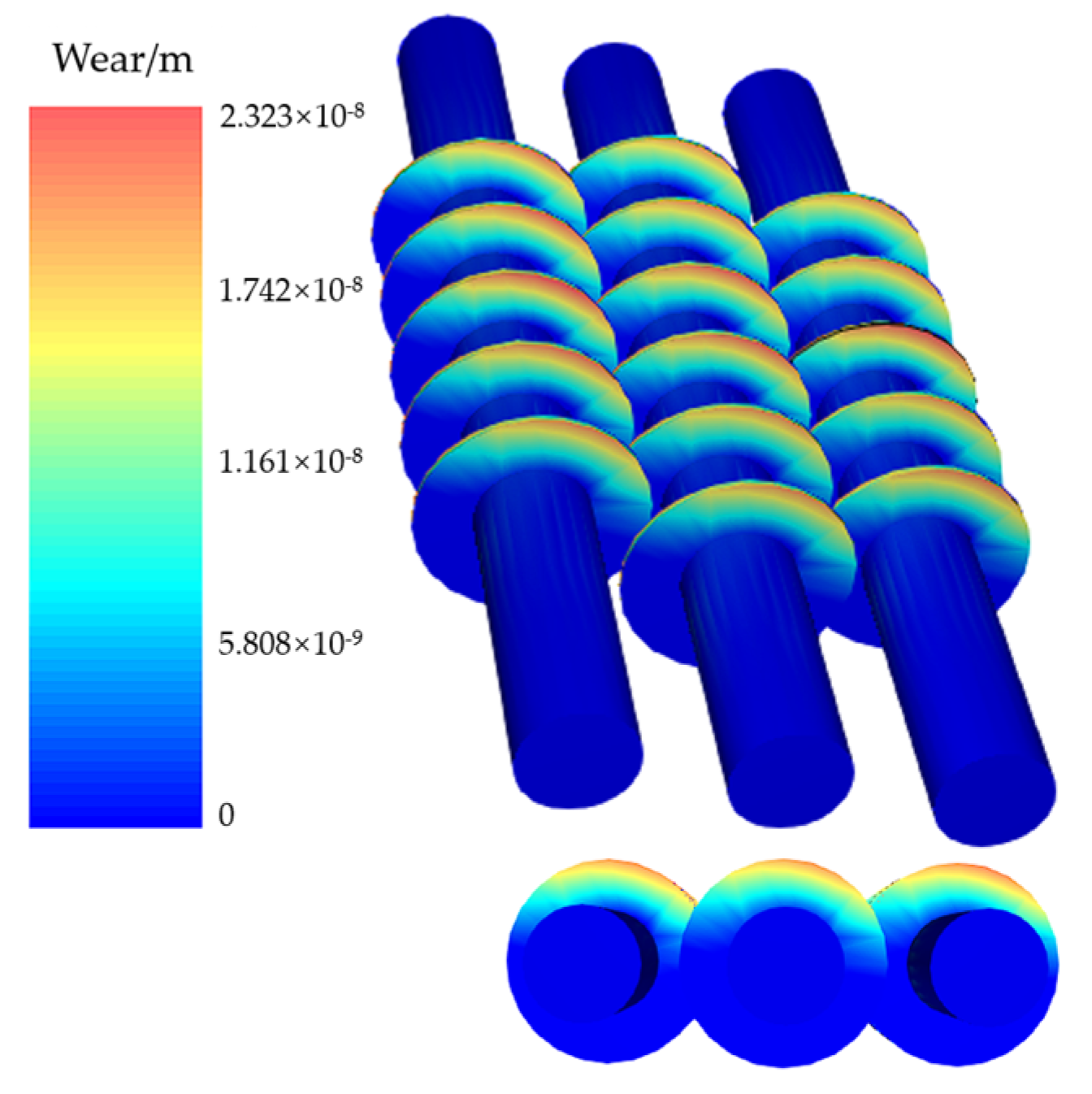
Figure 19 shows the wear cloud map of the loose roller with a feeding speed of 150 t/h. The figure shows the wear depth in the shaft direction, measured in meters. The loose roller blade edge is significantly worn, and the degree of wear increases from the inner axis outward. Each fan blade shows local wear, and the most severe part coincides with the area of maximum shear stress. According to the Formula (23) for wear depth derived from the previous text and the vertical wear depth cloud map calculated from DEM, it can be seen that the maximum wear amount of the loose roller within 100 s is 2.32 × 10⁻⁸ m. After the continuous operation of the hydrogen-based shaft furnace for one month, the monthly wear amount is calculated to be about 0.601 mm.

Figure 19.
Wear volume distribution for 150 t/h charging rate.
5. Conclusions
The following conclusions can be drawn from this study:
- (1)
- The maximum stress on the furnace wall in the output section of the hydrogen-based shaft furnace is 50,291.1 Pa when the feeding rate is 180 t/h. For every 10 t/h increase in feeding speed, the maximum stress on the furnace wall increases by 3052.9 Pa.
- (2)
- The wear coefficient of the refractory material in the reduction section is 4.88 × 10⁻¹⁶, and the wear coefficient of the steel shell in the cooling section is 1.17 × 10⁻¹³. The degree of wear on the cooling section is much greater than that on the reduction section.
- (3)
- Near the loosening roller, the maximum force on the DRI particles reached 39,744.3 N. At the core, 2.26 m below the material level in the reduction section, the maximum force on the pellet reaches 39,379.5 N.
- (4)
- According to the loose roller eccentric wear Formula (23) obtained in this article and the provided parameters, the degree of loose roller wear can be calculated. During the rotation of the loose roller, uneven force gradually causes irregular shape changes, resulting in more severe eccentric wear due to deformation.
- (5)
- There is a phenomenon of stress concentration in the inner shaft and fan blades of the loose roller, and the shear stress of the right loose roller reaches its maximum value of 219,896.1 Pa. The monthly wear of the loose roller is about 0.601 mm.
Author Contributions
Conceptualization, H.L. and Y.J.; software, H.L.; formal analysis, Z.L.; investigation, Z.H., Z.L. and P.L.; data curation, Y.J.; writing—original draft preparation, H.L.; writing—review and editing, Y.J., Z.H., Z.L. and P.L.; supervision, Y.J.; project administration, Y.J. All authors have read and agreed to the published version of the manuscript.
Funding
This research received no external funding.
Data Availability Statement
The original contributions presented in this study are included in the article. Further inquiries can be directed to the corresponding author.
Conflicts of Interest
The authors declare no conflicts of interest.
References
- Zhang, Q.; Shen, J.L.; Xu, L.S. Carbon peak and low-carbon transition path of China’s iron and steel industry. Iron Steel 2021, 56, 152–163. [Google Scholar]
- Shangguan, F.Q.; Liu, Z.D.; Yin, R.Y. Study on implementation path of “carbon peak” and “carbon neutrality” in steel industry in China. China Metall. 2021, 31, 15–20. [Google Scholar]
- He, L.L.; Zhang, H. China’s Energy Transformation Path Under “Double Carbon” Goal; Shanghai Energy Saving: Shanghai, China, 2023; pp. 1285–1294. [Google Scholar]
- Pan, Z.B. Development status and prospect of Chinese low-carbon ironmaking technology under carbon neutrality background. Sinter. Pelletizing 2024, 9, 5–41. [Google Scholar]
- Yu, Z.; Wang, Z.; Ma, L.; Ma, M. Energy-saving targets and carbon neutrality: A perspective on carbon emissions and carbon substitution in 288 Chinese cities. J. Environ. Manag. 2024, 356, 120523. [Google Scholar] [CrossRef]
- Lu, X.G.; Yu, W.; Zhu, K.; Li, G.; Ye, S. Development and key problems of hydrogen metallurgy. Chin. J. Nat. 2022, 44, 251–266. [Google Scholar]
- Jiang, Z.H.; Yang, C.; Zhu, H.C.; Lu, H. Research status and prospect of hydrogen metallurgy steelmaking technology. Iron Steel 2024, 59, 140–155. [Google Scholar]
- Zhang, J.L.; Zong, Y.B.; Li, K.J.; Li, Z.; Yang, T. Progress and future perspective of low-carbon ironmaking process in the world. Iron Steel 2024, 59, 45–55+155. [Google Scholar]
- Han, X.; Zhang, C.D.; Li, L.J.; Tian, Z.; Wang, X. Research status and prospects of hydrogen based shaft furnace direct reduction technology. Hebei Metall. 2024, 4, 1–5+11. [Google Scholar] [CrossRef]
- Shao, Y.J.; Xu, L.; Liu, X.P.; Cheng, H. Discussion on solution of “carbon neutrality” in China’s steel production. China Metall. 2022, 32, 1–8. [Google Scholar]
- Wang, X.D.; Hou, C.J.; Zhong, J.H. The development status of hydrogen industry and its application practice in China’s iron and steel industry. Hebei Metall. 2024, 32, 1–8. [Google Scholar]
- Chai, X.C.; Yue, Q.; Zhang, Y.J.; Wang, Q. Numerical simulation analysis of reduction domain in hydrogen metallurgy shaft furnace. Iron Steel 2022, 57, 138–147. [Google Scholar]
- Du, Y.M.; Guo, H.; You, G.; Mao, S.; Cao, W. Research progress of green and low-carbon hydrogen metallurgy technology. Min. Eng. 2024, 22, 62–65+69. [Google Scholar]
- Lu, L.J.; Wang, H.F.; Wang, F.; Qiu, J.; Ping, X. Development status and application of hydrogen metallurgy technology. Iron Steel 2024, 59, 183–196. [Google Scholar]
- Zhang, R.; Zhao, X.; Liu, Y.; Zhang, Q. Development pathway and influencing factors of hydrogen energy storage accommodating renewable energy growth. J. Energy Storage 2024, 87, 111441. [Google Scholar] [CrossRef]
- Bai, C.C.; Shi, X.F.; Wang, M.Y.; Yu, H.; Hu, C. Numerical simulation analysis of direct reduction of gas-based shaft furnace. Iron Steel 2024, 59, 41–48. [Google Scholar]
- Sun, F.R. Hydrogen based shaft furnaces assist traditional metallurgical industries in carbon reduction and upgrading. Shanxi Metall. 2023, 46, 89–91. [Google Scholar]
- Liu, J.H. Optimization of pellet production process for hydrogen-based shaft furnaces. Hebei Metall. 2024, 44–48. [Google Scholar] [CrossRef]
- Lu, P. Hydrogen-based shaft furnace production practice for increasing output and reducing consumption. Hebei Metall. 2024, 47–51. [Google Scholar] [CrossRef]
- Yu, Z.J. Process Features of ZXHT Hydrogen-based Shaft Furnace. Ironmaking 2024, 43, 65–68. [Google Scholar]
- Chen, T.R.; Wangz, M.; Qin, H.B.; Liang, K.; Li, X. Research progress on hydrogen metallurgy process and refractories for hydrogen-based shaft furnaces. Refractories 2024, 58, 263–269. [Google Scholar]
- Zhang, H.; Liu, M.L.; Huang, Z.Y.; Bo, H. DEM simulation and analysis of collision between single coarse particle and wall. At. Energy Sci. Technol. 2017, 51, 2212–2217. [Google Scholar]
- Xu, Q.; Ye, J.H. Structural contact-collision behavior analysis based on bar system discrete element method. J. Vib. Shock 2023, 42, 103–110. [Google Scholar]
- Huang, L.J.; Liu, X.D.; Su, S.Q. Numerical simulation on breaking behavior of spheroidal particles impact based on discrete element method. China Powder Sci. Technol. 2014, 20, 60–63. [Google Scholar]
- Kuang, D.-M.; Long, Z.-L.; Zhao, T.; Luo, B.; Ogwu, I.; Kuang, F.-L. Modeling the single particle crushing behavior by random discrete element method. Constr. Build. Mater. 2024, 411, 134519. [Google Scholar] [CrossRef]
- You, Y.; Zhou, H.; Zhang, T.; Luo, Z.; Zhou, Z. Modeling of solid flow in COREX shaft furnace with AGD introduced by discrete element method. J. Mater. Metall. 2016, 15, 6–11. [Google Scholar]
- Zhang, Q.X. Analysis of Potato Collision Problem and Research and Development of Key Components of Separator Based on Discrete Element. Master’s Thesis, Shandong University of Technology, Zibo, China, 2022. [Google Scholar]
- Ma, K.; Deng, J.; Wang, G.; Zhou, Q.; Xu, J. Utilization and impacts of hydrogen in the ironmaking processes: A review from lab-scale basics to industrial practices. Int. J. Hydrogen Energy 2021, 46, 26646. [Google Scholar] [CrossRef]
- Zhou, H.; Luo, Z.; Zou, Z.; Zhang, T.; You, Y. Experimental study on burden descending behavior in COREX shaft furnace with AGD beams. Steel Res. Int. 2015, 86, 1073–1081. [Google Scholar] [CrossRef]
- Zhang, B.L. DEM Modeling of the Flow Characteristics of Granular Materials in Moving Beds. Master’s Thesis, China University of Petroleum, Beijing, China, 2023. [Google Scholar]
- Shen, Q.J.; Dong, S.J.; Zhang, D.C.; Guo, H.; Song, Y. DEM modeling of resonant motion of particles inside moving bed. Chin. J. Process Eng. 2023, 23, 826–836. [Google Scholar]
- Liu, J.D. DEM Modeling of the Discharge Features of Moving Bed. Master’s Thesis, University of Science and Technology Liaoning, Anshan, China, 2022. [Google Scholar]
- Li, H.F.; Zhou, H.; Luo, Z.G.; Zhang, T.; You, Y.; Zou, Z.S. Three-dimensional discrete element method simulation of the effect of bottom structure on solid flow in COREX shaft furnace. Can. Metall. Q. 2016, 55, 112–123. [Google Scholar] [CrossRef]
- Du, B.B.; Wu, S.L.; Zhou, H.; Kou, M. Effect of scaffolding on solid flow in COREX shaft furnace by discrete element simulation method. Iron Steel 2020, 55, 12–19. [Google Scholar]
- Ma, S.H.; Ji, Z.J.; Cai, X.C.; Ji, M. Research on the bearing wear characteristics of wind turbine based on finite element analysis and Archard model. J. Qinghai Univ. 2024, 42, 70–77+106. [Google Scholar]
- Gao, J.F.; Zhao, J.Y.; Feng, Y.L.; Yang, L.; Li, W. Research of wear behavior of discontinuous contact floating ball seal structure based on modified Archard wear model. Fluid Mach. 2024, 52, 20–27. [Google Scholar] [CrossRef]
- Zhou, S.X.; Lei, Z.Y.; Qin, Z.; Niu, L.; Bai, X. Optimization of Disc Braking Correction Indexes Based on Archard Wear Theory. China Railw. Sci. 2022, 43, 129–138. [Google Scholar]
- Yang, X.J.; Zhu, X.L. Study on wear of warm upsetting mold for non-standard pin shaft based on revised Archard wear theory. Forg. Stamp. Technol. 2021, 46, 32–37. [Google Scholar]
- Fan, W.; Shui, P.; Xie, C.D.; Gao, L. Research and Optimization of Wear Evolution Law of High Pressure Roller Mill Based on Archard Model and DEM Simulation. Metal Mine 2024, 173–180. [Google Scholar]
- Xie, W.X.; Su, Q.X.; Guo, L.Q.; Sun, Z.; Zhang, L.; Gu, W.; Zhang, X. Analysis on wear law of friction pair of oil-well pump barrel-plunger based on, ANSYS. China Pet. Mach. 2022, 50, 115–121. [Google Scholar]
- Wei, D.; Wei, P.T.; Liu, H.J. Wear behavior and simulation analysis of micro gear tooth surface. J. Chongqing Univ. 2022, 45, 22–30. [Google Scholar]


Disclaimer/Publisher’s Note: The statements, opinions and data contained in all publications are solely those of the individual author(s) and contributor(s) and not of MDPI and/or the editor(s). MDPI and/or the editor(s) disclaim responsibility for any injury to people or property resulting from any ideas, methods, instructions or products referred to in the content. |
© 2025 by the authors. Licensee MDPI, Basel, Switzerland. This article is an open access article distributed under the terms and conditions of the Creative Commons Attribution (CC BY) license (https://creativecommons.org/licenses/by/4.0/).