Article

Transient Collapse Failure Prediction of Production Casing After Packer Unsetting in High-Pressure and High-Temperature Deep Oil Wells

1
School of Petroleum and Natural Gas Engineering, Chongqing University of Science & Technology, Chongqing 401331, China
2
Safety and Environment Protection Technology Supervision Center of PetrChina Liaohe Oilfield Company, Panjin 124010, China
3
No. 4 Oil Extraction Plant, Sinopec Northwest Oilfield Company, Shaya 842200, China
4
State Key Laboratory of Oil & Gas Reservoir Geology and Exploitation, Southwest Petroleum University, Chengdu 610500, China
*
Author to whom correspondence should be addressed.
Processes 2025, 13(3), 839; https://doi.org/10.3390/pr13030839
Submission received: 9 January 2025 / Revised: 25 February 2025 / Accepted: 5 March 2025 / Published: 12 March 2025
(This article belongs to the Topic Petroleum and Gas Engineering, 2nd edition)

Abstract

:
The abnormal swab pressure resulting from packer unsetting poses a great threat to the collapse resistance of production casings in deep high-pressure and high-temperature (HPHT) oil wells. This paper proposes an analytical model to predict the transient swab pressure in the A-annulus after packer unsetting based on a U-type tube and an iterative method. The model can further evaluate the collapse failure risk of the production casing in the whole wellbore. An example study and sensitivity analysis were carried out to reveal the variation characteristics of the transient swab pressure in the A-annulus and the failure risk of the production casing after packer unsetting. Furthermore, some preventative measures are proposed. The largest swab pressure occurs at the initial time of packer unsetting, which will lead to sudden collapse failure of the deeper production casing. A smaller width of the annular clearance between the packer rubber and production casing and a larger initial liquid level depth in the A-annulus can reduce the swab pressure in the A-annulus after packer unsetting and collapse failure risk of the production casing. In the example, when the width of the annular clearance decreased from 2.97 to 2 mm, the maximum swab pressure decreased from 88.71 to 27.4 MPa, a decrease of 69.1%. When the initial liquid level depth in the A-annulus increased from 700 to 900 m, the maximum swab pressure decreased from 122 to 57.05 MPa, a decrease of 53.2%. When the width of annular clearance was 2.97 mm, the collapse resistance safety factors for the production casing were less than 1.1 and may suffer from collapse failure for well depth between 3610 m and 6100 m. When the initial liquid level depth in the A-annulus was 700 m, the production casing will suffer from collapse failure for well depth between 2869 m and 6100 m. When the width of the annular clearance was less than 2.5 mm and the initial liquid level depth in the A-annulus was larger than 900 m, the collapse resistance safety factors for the production casing were all greater than 1.1 and the whole production casing was safe. To lower the collapse failure risk of the production casing because of packer unsetting, a packer rubber with a reasonable larger outer diameter and good deformation recovery ability is recommended, and the initial liquid level depth in the A-annulus should be controlled reasonably. The research results are of great significance for preventing the collapse failure of production casings during packer unsetting.

1. Introduction

Cemented casing collapse failures are usually encountered in deep high-pressure and high-temperature (HPHT) formations, creep salt zones, and locally expansive mudstone and shale formations, and these failures are one of the most significant problems that must be solved for oilfield production safety [1,2]. The key to solving this problem lies in two aspects: accurately calculating the effective external pressure acting on the casing and selecting high-strength casings with thick walls and/or a high steel grade to resist the larger external pressure from those abnormal formations [3,4]. The former depends to a great extent on the method used and the factors considered. The basic and earliest method was to adopt a hydrostatic pressure formula for calculating the casing external pressure, but it is not suitable for rheological formations and many practical situations.
By establishing a combined casing–cement sheath–formation geomechanical model, the theoretical models and numerical modeling approaches are presently generally used for investigating complex casing collapse failure problems resulting from combined loads, formation creep, sliding on faults, casing defects, and borehole curvature. Zhou et al. proposed a new equation for calculating medium-thickness casing collapse strength under combined loads, which considers the effects of shear load influence, as well as non-uniformity of the external load [5]. By adopting a geomechanical and numerical analysis method, Dashtaki et al. have tried to model several collapse loadings of a rock–cement–casing system under real conditions of in situ stress and geomechanical properties of different lithology, cement, and casing [6]. By establishing the finite element model for structural faults, Hou et al. carried out quantity analysis between the rock formation slippage and the casing strength and analyzed the influence of casing load by simulating a parallel wellbore fault and shear casing fault [7]. Based on finite element analysis, Liu et al. demonstrated that pit depth and pit circumferential spread are the main controlling factors which affect the collapse strength of the defective casing and then developed a formula for steam injection wells to calculate the collapse strength of the defective casing by including the effect of temperature on the degradation of the yield strength and compression stress function of a cylinder in the existing collapse strength formula [8]. Cao et al. have conducted a theoretical and simulation study on the collapse strength of a curved casing in horizontal wells [9]. By using the geomechanical finite element modeling method, Kaveh et al. investigated the effect of cement sheath integrity on casing collapse, which revealed that the casing collapse in the case study can be highly attributed to the cement sheath shear failure and migration of the over-pressured formation fluid to the micro-annuli formed at the cement interfaces with the formation and the casing due to plastic deformation [10].
In recent years, reliability analysis and machine learning have gradually come to be used in casing collapse failure risk assessment. Mohamadian et al. investigated casing collapse in wellbores from an established petroleum geomechanics perspective to develop and compare two hybrid neural network models tuned with multilayer perceptrons and a genetic algorithm and a particle swarm algorithm [11]. To identify zones at risk of casing collapse due to shear stress buildups, Rashidi et al. proposed a practical method for predicting geomechanical characteristics along an entire wellbore by combining machine learning algorithms and optimizers and calibrating with a few mechanical rock test measurements [12]. With structural reliability analysis, Buchmiller et al. calculated the probability of failure for production casing collapse as a function of the differential pressure [13]. Zhu and Liu developed the reliability evaluation method for the casing collapsing strength in marine gas reservoirs based on the standard of collapsing strength and the load–strength interference model [14].
The above investigations indeed provide meaningful evaluation methods for casing collapse failure risk prediction under complex geological conditions. However, the present investigations and relevant specifications for casing design [15,16] all consider the inner pressure of the supporting casing as a static liquid column pressure and, sometimes, a certain hollowing depth is considered because of lost circulation, which is not applicable to some special situations like packer unsetting. In western China, some deep high-pressure and high-temperature (HPHT) oil wells have undergone instantaneous casing collapse failure due to packer unsetting, which poses a significant threat to well integrity.
The packer is an important safety barrier for sealing tubing and production casings in deep HPHT oil wells. The setting of the packer forms an A-annulus between the tubing and the production casing. Generally, the A-annulus is filled with a completion fluid, whose hydrostatic pressure supports the production casing and reduces the risk of casing collapse failure. However, because of rubber stress relaxation, rubber aging, rubber corrosion, and perforation impact loads [17,18,19,20], the packer undergoes normal or abnormal unsetting during oil production and downhole operations, such as workover for changing the production tubing, and the A-annulus and tubing will form a U-type tube. Because the density of the completion fluid is generally greater than that of oil in the tubing and the tubing liquid surface will also decrease with formation pressure exhaustion, a significant positive pressure differential will occur between the upper and lower sections of the packer during packer unsetting. The pressure differential will drive the completion fluid downward through the small annular clearance between the packer rubber tube and inner wall of the production casing, thus producing a significant swab pressure in the production casing, which is similar to reverse circulation in a concentric annulus [21]. The swab pressure will directly lead to an enlarged effective external pressure acting on the production casing, which may result in a sudden collapse failure of the production casing. Consequently, the prediction of transient collapse failure for a production casing during packer unsetting is of great significance to ensure wellbore integrity for deep HPHT oil wells.

2. Model Development

2.1. Basic Assumptions

Figure 1 shows a sketch of the well structure with packer completion, and Figure 2 illustrates the packer setting and unsetting statuses. When the packer is setting, the A-annulus is nearly filled with completion fluid and separated from the oil layer, and the oil can flow to the ground though the tubing. At this moment, the hydrostatic pressure of the completion fluid supports the production casing. However, when the packer is unsetting, the completion fluid will flow downward through the micro-annulus between the packer rubber and production casing, which will produce a swab pressure and lower the effective hydrostatic pressure of the completion fluid. When calculating the swab pressure resulting from the flowing completion fluid, some basic assumptions have been made:
(1)
The production casing, tubing, and packer rubber are concentric cylinders.
(2)
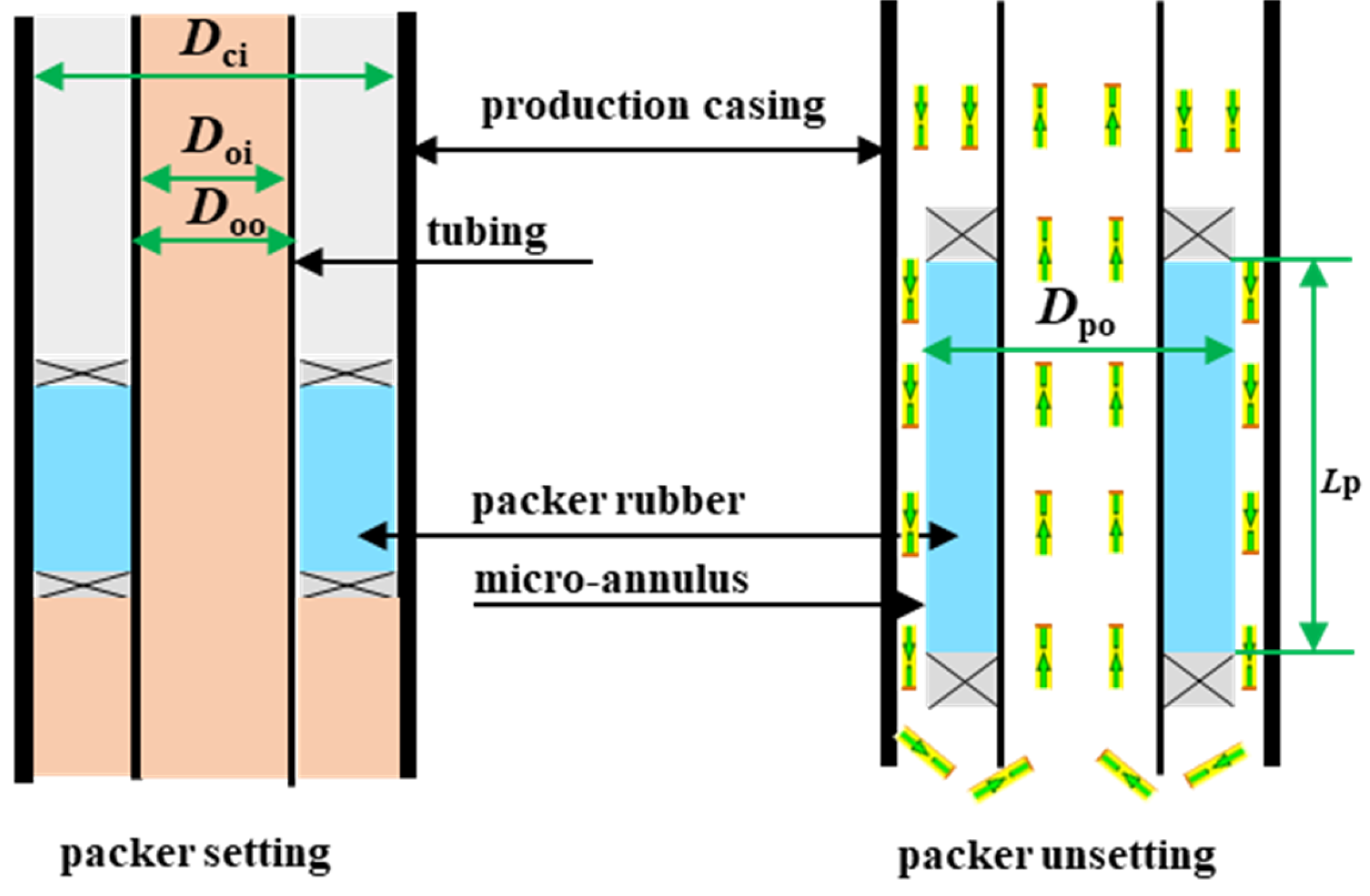
The width of the annular clearance between the packer rubber and production casing are only changed by the radial deformation of the packer rubber, which means that the wall thickness reduction from corrosion or mechanical damage is ignored for the production casing and packer rubber.
(3)
The completion fluid and oil are both regarded as incompressible and inviscid ideal fluids.
(4)
After the packer unsetting, the deformation of the packer rubber recovers in a very short time and a micro-annulus forms between the rubber and production casing.
(5)
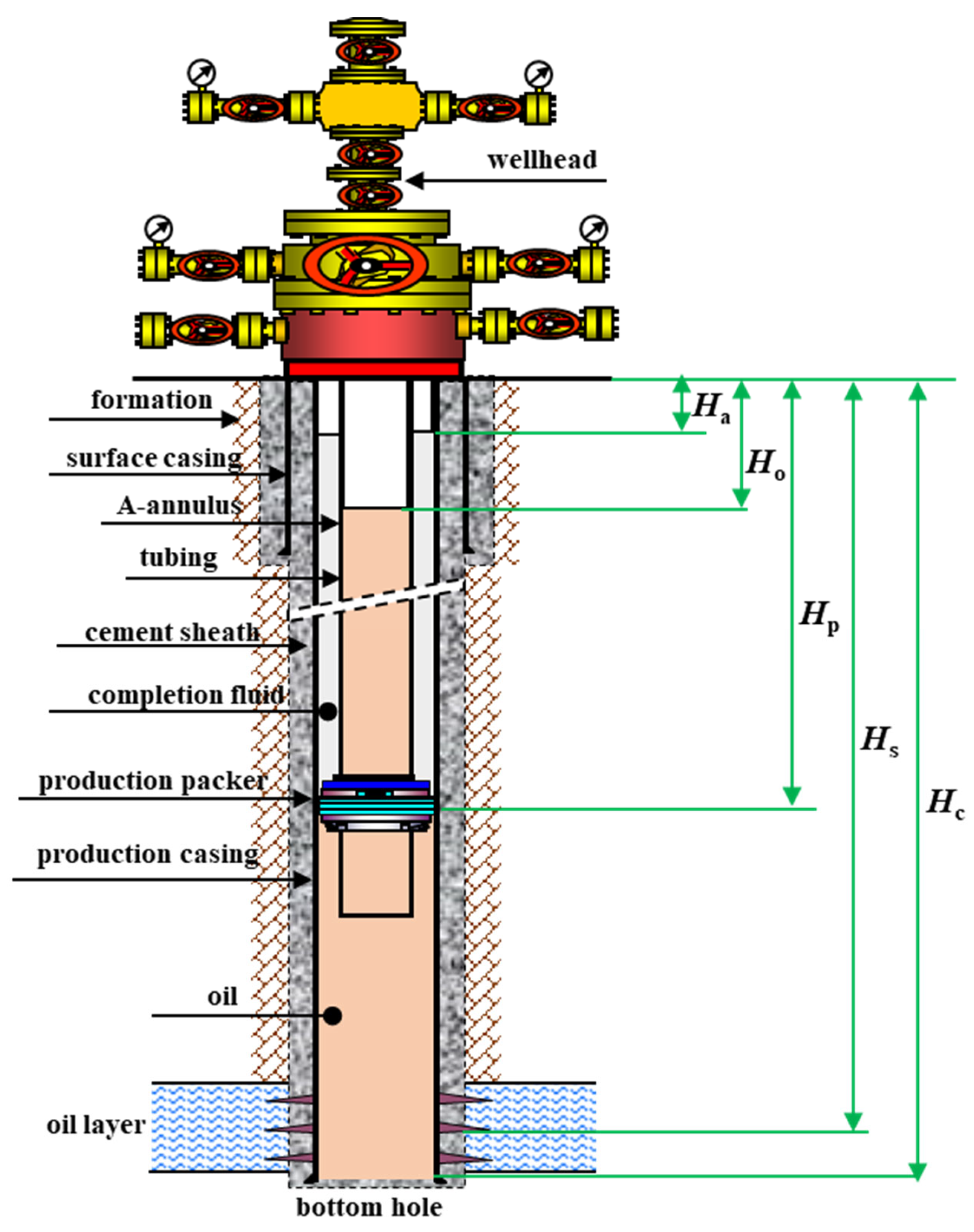
The A-annulus and tubing are connected to form a U-type tube, and the location of the production packer can be regarded as a constant-pressure surface.
Figure 1. Sketch of well structure with packer completion.
Processes 13 00839 g001
Figure 2. Packer setting and unsetting statuses.
Processes 13 00839 g002
To predict the transient collapse failure risk of the production casing after packer unsetting, the methodology includes two main steps; one is to calculate the transient swab pressure after packer unsetting, and the other is to predict the collapse failure risk of the production casing by calculating the collapse resistance safety factor, and these are described in detail in Section 2.2 and Section 2.3, respectively.

2.2. Transient Swab Pressure After Packer Unsetting

At the initial time of packer unsetting (t = 0), the pressure difference between the upper and lower packer is as follows:
Δ P p t = 0 = H p H a t = 0 ρ c g H p H o t = 0 ρ o g
In Equation (1), the liquid level depth in the tubing can be calculated using the static pressure of the oil layer:
H o t = 0 = H w P f ρ o g .
According to Bernoulli’s equation [22], under the action of ΔPp, the initial flow velocity of the completion fluid in the micro-annulus between the packer rubber and production casing can be expressed as
V p t = 0 = 2 g λ D ci D po L p L p + Δ P p t = 0 ρ c g .
In Equation (3), the hydraulic friction coefficient can be calculated by [23]
λ = 64 R e f o r l a m i n a r   f l o w R e 2000 0.3164 R e 1 / 4 f o r t u r b u l e n t   f l o w 2000 < R e 10 5 .
In Equation (4), the Reynolds number for the flowing completion fluid in the micro-annulus can be calculated by
R e 1 t = 0 = ρ c D ci D po V p t = 0 μ c .
We assume that the flow in the micro-annulus between the packer rubber and the production casing is laminar. By inserting Equations (4) and (5) into Equation (3), the corresponding assuming laminar flow velocity of the completion fluid in the micro-annulus can be obtained:
V p 1 t = 0 = 1 32 ρ c g D ci D po 2 L p μ c L p + Δ P p t = 0 ρ c g .
Similarly, the corresponding equation assuming turbulent flow of the completion fluid in the micro-annulus can be obtained:
V p 2 t = 0 = 2 g 0.3164 ρ c μ c 1 / 4 D ci D po 5 / 4 L p L p + Δ P p t = 0 ρ c g 4 / 7 .
Letting Vp in Equation (5) equal Vp1 in Equation (6) and combining Equations (4), (6), and (7), we can determine the flow velocity of the completion fluid in the micro-annulus between the packer rubber and production casing:
V p t = 0 = V p 1 t = 0 i f ρ c 2 g D ci D po 3 L p μ c 2 L p + Δ P p t = 0 ρ c g 64,000 V p 2 t = 0 i f ρ c 2 g D ci D po 3 L p μ c 2 L p + Δ P p t = 0 ρ c g > 64,000 .
According to the continuity of the flow in the U-type tube, we can easily obtain the flow velocity of the completion fluid in the A-annulus at the initial time of packer unsetting:
V a t = 0 = V p t = 0 D ci 2 D po 2 D ci 2 D oo 2 .
The Reynolds number for the flowing completion fluid in the A-annulus can be calculated by
R e 2 t = 0 = ρ c D ci D oo V a t = 0 μ c .
Then, by inserting Equation (10) into Equation (4), we can also calculate the hydraulic friction coefficient in the A-annulus, and the swab pressure in the A-annulus at the initial time of packer unsetting can be further obtained by
P s t = 0 = λ 2 ρ c H p H a t = 0 D ci D oo V a 2 t = 0 .
Adopting the same analysis method, we can acquire the final expression for Ps:
P s t = 0 = 32 μ c H p H a t = 0 D ci D oo 2 V a t = 0 i f ρ c D ci D oo μ c V a t = 0 2000 0.1582 μ c 1 / 4 ρ c 3 / 4 H p H a t = 0 D ci D oo 5 / 4 V a 7 / 4 t = 0 i f ρ c D ci D oo μ c V a t = 0 > 2000 .
Furthermore, with the recurrence method, we can obtain the swab pressure in the A-annulus at any time after packer unsetting. Assuming that the time step of the recursion is Δt, after the time interval of iΔt, the liquid level depth in the A-annulus changes to
H a t = i Δ t = H a t = ( i 1 ) Δ t + Δ t V a t = ( i 1 ) Δ t ( i = 1 , 2 , ) .
At the same time, due to the continuity of the flow in the U-type tube, the liquid level depth in tubing changes to
H o t = i Δ t = H o t = ( i 1 ) Δ t D ci 2 D oo 2 D oi 2 Δ t V a t = ( i 1 ) Δ t ( i = 1 , 2 , ) .
By iteratively solving Equations (13) and (14) and repeating the calculation process above, we obtain the swab pressure in A-annulus at any time after packer unsetting with Microsoft Visual Basic 6.0 programming. The workflow is shown in Figure 3.

2.3. Collapse Failure Prediction of Production Casing

The inner pressure of the supporting production casing at the time iΔt can be expressed as
P ci t = i Δ t H = 0 i f H H a t = i Δ t ρ c g H H a t = i Δ t H H a t = i Δ t H p H a t = i Δ t P s t = i Δ t i f H a t = i Δ t < H H p ρ o g H H p + ρ c g H p H a t = i Δ t P s t = i Δ t i f H p < H H c .
The effective collapse pressure acting on the outer wall of the production casing is
P ce t = i Δ t H = ρ w g H P ci t = i Δ t H .
Thus, the collapse resistance safety factor for the production casing is as follows:
S ce H = P c P ce t = i Δ t H

3. Example Study

3.1. Basic Parameters

A deep HPHT oil well M was cemented with a Ø177.8 mm × 12.65 mm P110 production casing, and it had well completion strings with Ø88.9 mm × 6.45 mm P110 tubing and a Ø177.8-mm PHP-2 packer. The basic parameters for well M are listed in Table 1.

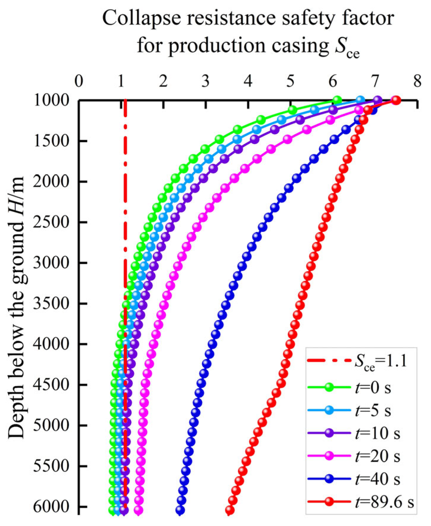
3.2. Prediction Results and Model Validation

According to Equations (15)–(17), the two key parameters that influence the transient collapse failure of the production casing after packer unsetting are the liquid level depth in the A-annulus and the swab pressure resulting from the downward flowing completion fluid in the A-annulus, which are respectively shown in Figure 4 and Figure 5. It can be clearly observed from Figure 4 that after packer unsetting, the liquid level depth in the A-annulus continued to decrease and the decrease rate gradually diminished. The terminal liquid level depth in the A-annulus decreased from 800 to 1094.75 m at the time of 89.6 s after the packer unsetting. Figure 5 shows similar variation patterns for the swab pressure in the A-annulus, and its largest value of 88.71 MPa occurred at the initial time of packer unsetting.
The collapse resistance safety factors for the production casing at different times after packer unsetting were obtained using Equations (15)–(17), which are shown in Figure 6. Because the intermediate casing was set at a depth of 1000 m, the range of the depth below the ground in Figure 6 was considered from 1000 to 6100 m. It can be clearly seen from Figure 6 that the deeper production casing suffered from collapse failure during the initial 10 s after packer unsetting, and the maximum collapse failure well section for the production casing was between 3928 and 6100 m at the initial time after packer unsetting, which corresponded to the field testing results by downhole television of the production casing deformation for well M after packer unsetting, the diameter of the production casing reduced to 179 mm from the initial 224 mm, as shown in Figure 7. This indicated that the swab pressure in the A-annulus resulting from the downward flowing completion fluid after packer unsetting significantly lowered the inner pressure supporting production casing, thus leading to its collapse failure. Consequently, necessary measures should be proposed to avoid this sudden collapse failure of the production casing.

3.3. Sensitivity Analysis

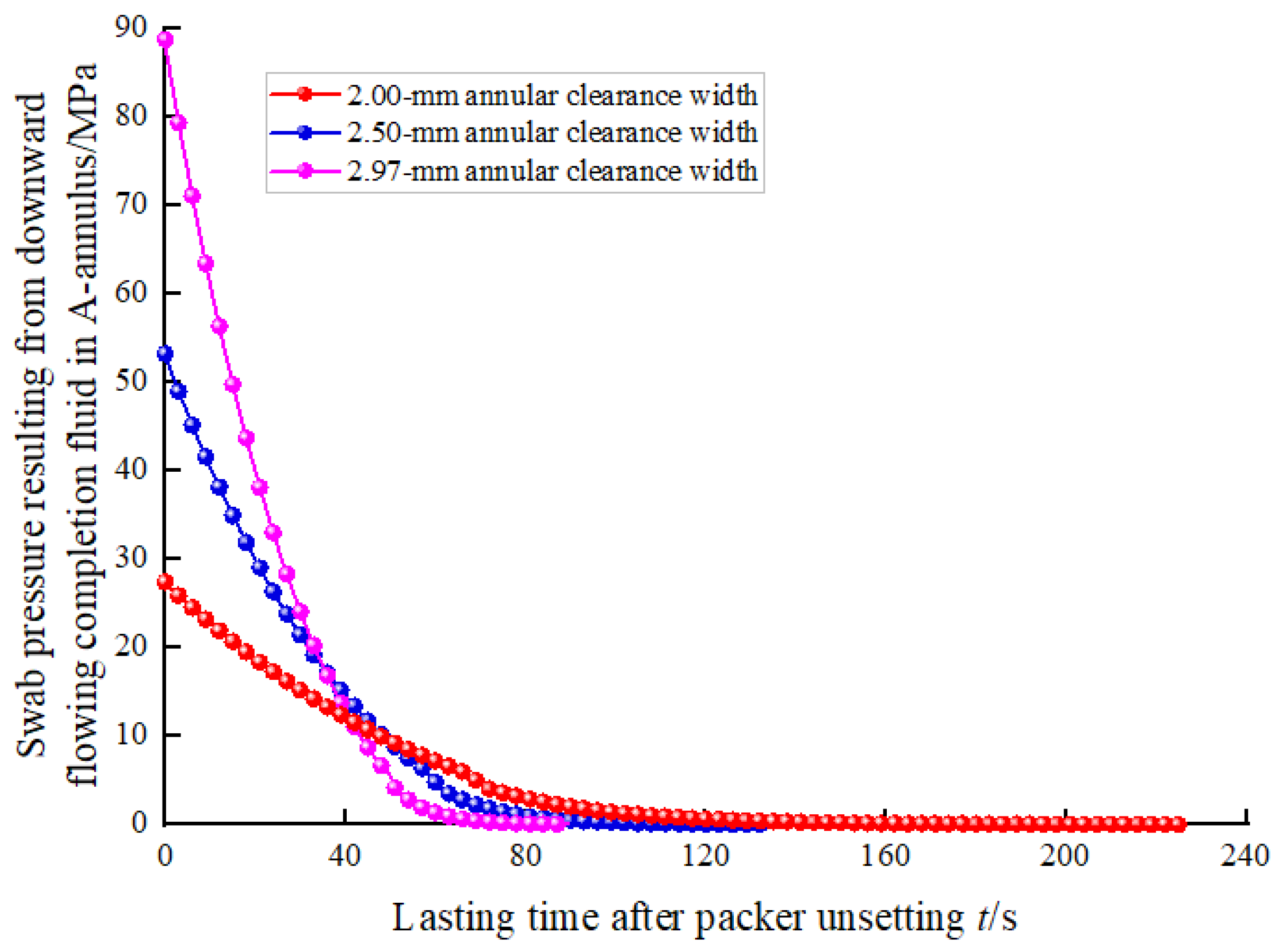
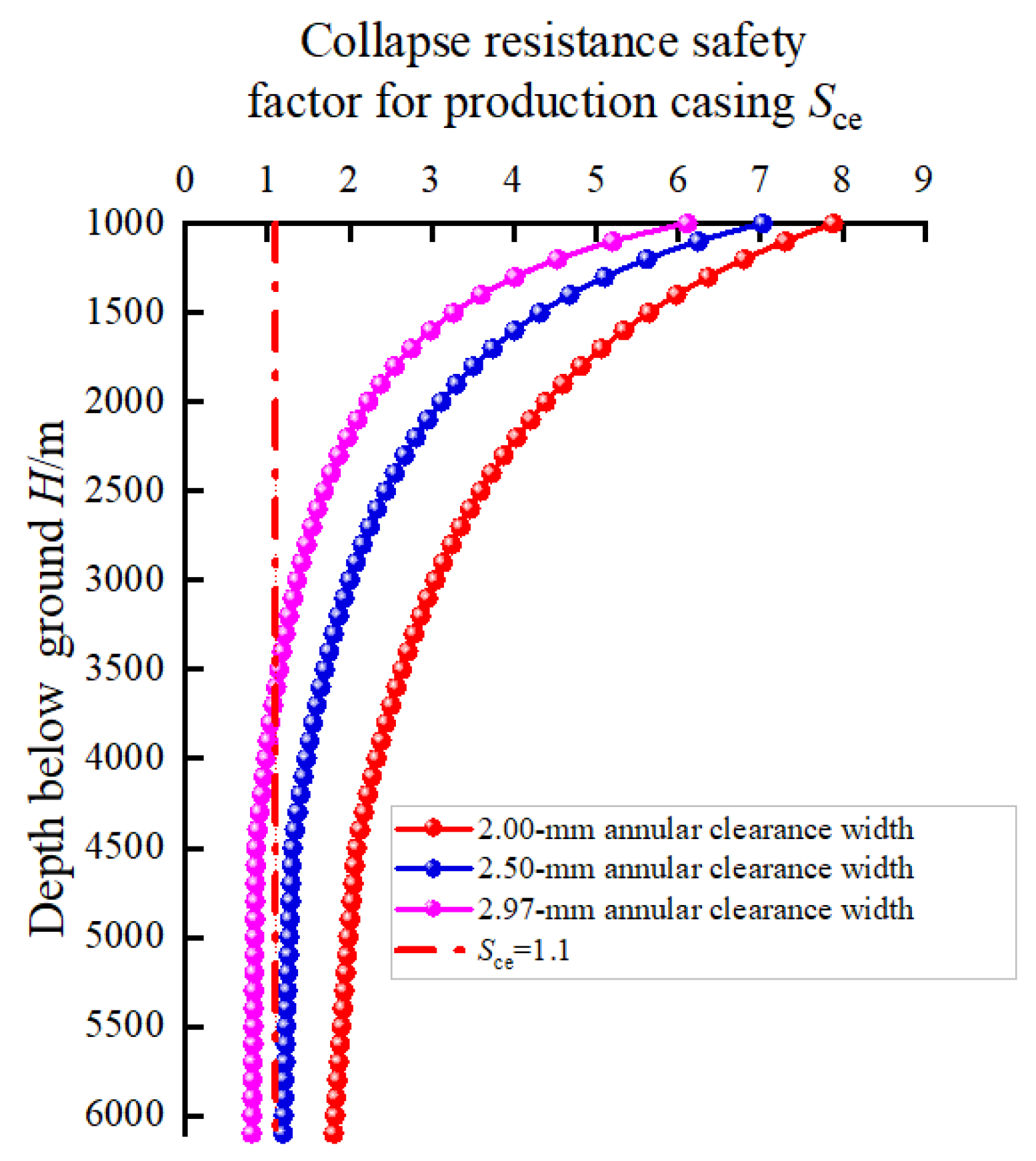
3.3.1. Width of Annular Clearance Between Packer Rubber and Production Casing

In practice, it is difficult to accurately predict the width of the annular clearance between the packer rubber and the production casing after packer unsetting, which is because the deformation of the packer rubber is a complex viscoelastic mechanical behavior. According to Table 1, supposing the radial deformation of the packer rubber recovered completely after packer unsetting, the width of the annular clearance was 2.97 mm, so three different annular clearance widths of 2, 2.5, and 2.97 mm were selected for sensitivity analysis. After packer unsetting, the liquid level depth in the A-annulus, the swab pressure in the A-annulus, and the collapse resistance safety factor for the production casing with annular clearance widths of 2, 2.5, and 2.97 mm are shown in Figure 8, Figure 9, and Figure 10, respectively. Figure 8 shows that the smaller the width of the annular clearance was, the more time was needed for the liquid level depth in the A-annulus to decrease to reach the final stable value of 1094.75 m. The times were 226.4, 132, and 89.6 s for annular clearance widths of 2, 2.5, and 2.97 mm, respectively. Figure 9 indicates that with the decrease in the annular clearance width, the swab pressure in the A-annulus significantly decreased. When the width of the annular clearance decreased from 2.97 to 2 mm, the maximum swab pressure due to the packer unsetting decreased from 88.71 to 27.4 MPa, a decrease of 69.1%. Figure 10 also shows that a smaller width of the annular clearance was helpful for protecting the production casing during packer unsetting. When the width of annular clearance was 2.97 mm, the collapse resistance safety factors for the production casing were less than 1.1 and may suffer from collapse failure for the well depth between 3610 m and 6100 m. When the width of annular clearance was smaller than 2.5 mm, the collapse resistance safety factors for the production casing were all more than 1.1, indicating the whole production casing will not suffer from collapse failure. In addition, because the aging and plastic deformation of the rubber will occur after a long time in a downhole HPHT environment, the radial deformation of the packer rubber will not be able to recover completely after packer unsetting. Consequently, the packer rubber with a reasonable larger outer diameter and good deformation recovery ability should be recommended for lowering the collapse failure risk of the production casing because of packer unsetting.

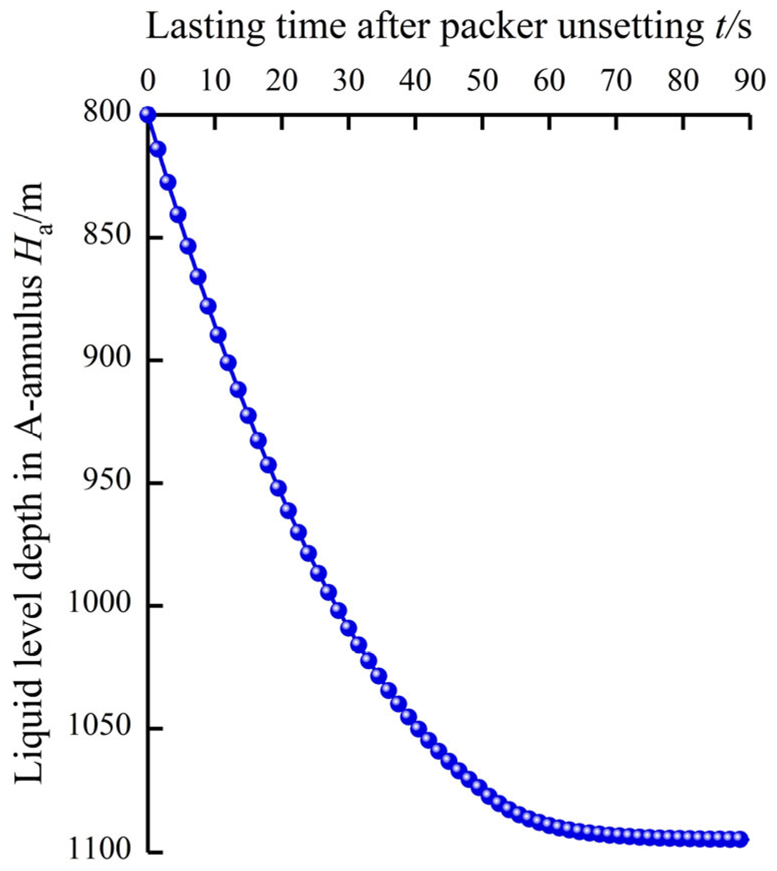
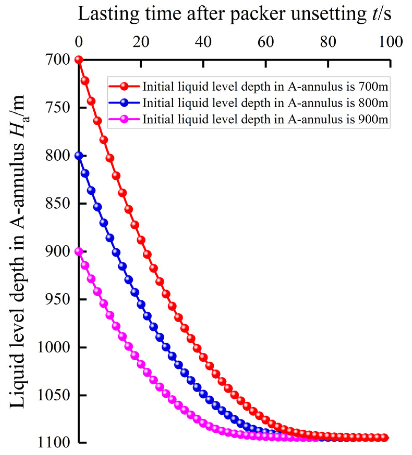
3.3.2. Initial Liquid Level Depth in A-Annulus

The initial liquid level in the A-annulus after well completion is usually near the wellhead. However, the liquid level in the A-annulus may gradually decrease because of packer leakage. Thus, the initial liquid level depth in the A-annulus during packer unsetting was assumed to be 700, 800, and 900 m for sensitivity analysis. After packer unsetting, the liquid level depth in the A-annulus, the swab pressure in the A-annulus, and the collapse resistance safety factor for the production casing under three different initial liquid level depths in the A-annulus are shown in Figure 11, Figure 12, and Figure 13, respectively.
Figure 11 shows that the smaller the initial liquid level depth in the A-annulus was, the more time was needed for the liquid level depth in the A-annulus to decrease to the terminal stable value of 1094.75 m. The required times were 99.3, 89.6, and 77.7 s for initial liquid level depths of 700, 800, and 900 m, respectively. Figure 12 indicates that with the increase in the initial liquid level depth in the A-annulus, the swab pressure in the A-annulus significantly decreased. When the initial liquid level depth in the A-annulus increased from 700 to 900 m, the maximum swab pressure due to packer unsetting decreased from 122 to 57.05 MPa, a decrease of 53.2%. Figure 13 also shows that a larger initial liquid level depth in the A-annulus was beneficial for protecting the production casing during packer unsetting. When the initial liquid level depth in the A-annulus was 700 m, the collapse resistance safety factors for the production casing were less than 1.1 and may have suffered from collapse failure for the well depth between 2869 m and 6100 m. When the initial liquid level depth in the A-annulus was 800 m, the collapse resistance safety factors for the production casing were less than 1.1 and may suffer from collapse failure for the well depth between 3610 m and 6100 m. When the initial liquid level depth in the A-annulus was larger than 900 m, the collapse resistance safety factors for the production casing were all more than 1.1, which indicating the whole production casing will not suffer from collapse failure. Consequently, to lower the collapse failure risk of the production casing due to packer unsetting, the initial liquid level depth in the A-annulus should be controlled reasonably before packer unsetting.

4. Discussion

The mode presented in this paper focuses on the transient collapse failure prediction of the production casing after packer unsetting in HPHT deep oil wells, and the case validation and sensitivity analysis verified the reliability of the model and provided the solution to prevent casing collapse after packer unsetting. However, some basic assumptions may reduce the practicality and accuracy of the model. For example, some basic parameters like the width of annular clearance and the initial liquid level depth in the A-annulus may be random and variable, and a reliability model may be more beneficial to judge the failure risk of production casing under this situation. Meanwhile, among the recommendations proposed in this paper, packer rubber with a reasonable larger outer diameter and good deformation recovery ability can be implemented by packer design and material optimization to satisfy the practical HPHT environment, and the initial liquid level depth in the A-annulus can be reasonably controlled by an annular protection fluid automatic pumping device and ultrasonic liquid-level automatic detector. Although this will entail some investment in equipment and research, those recommendations can effectively reduce the collapse failure risk of the production casing and enhance well integrity, thus ensuring the safe production of oil wells and saving the cost of casing repair in the long term. Because of some basic assumptions during model building, the present model in this paper can be also further improved by considering more complex well completion geometries, such as deviated wells, branching wells, and multi-packer completion, and the effects of non-Newtonian fluids and the randomness of the parameters on the transient swab pressure after packer unsetting in future work.

5. Conclusions

(1)
This paper first proposes an analytical model to predict the transient swab pressure after packer unsetting and evaluates the collapse failure risk of the production casing in deep HPHT oil wells.
(2)
The largest swab pressure occurs at the initial time of packer unsetting, which would lead to collapse failure of the deeper production casing.
(3)
After packer unsetting, a smaller width of the annular clearance between the packer rubber and production casing and a larger initial liquid level depth in the A-annulus can both reduce the swab pressure in the A-annulus.
(4)
To lower the collapse failure risk of the production casing because of packer unsetting, packer rubber with a reasonable larger outer diameter and good deformation recovery ability is recommended, and the initial liquid level depth in the A-annulus should be reasonably controlled.
(5)
The present model can be further improved by considering more complex well completion geometries and the effects of non-Newtonian fluids and the randomness of the parameters on the transient swab pressure after packer unsetting.

Author Contributions

Conceptualization, H.-L.X. and Z.Z.; Methodology, H.-L.X.; Validation, H.-L.X. and X.-D.W.; Formal analysis, H.-L.X.; Investigation, H.-L.X., S.-L.X., D.-D.P. and X.-D.W.; Writing—original draft, H.-L.X. and S.-L.X.; Writing—review and editing, H.-L.X.; Supervision, Z.Z.; Funding acquisition, H.-L.X. All authors have read and agreed to the published version of the manuscript.

Funding

This research was funded by the National Natural Science Foundation of China (51804060) and the Natural Science Foundation of Chongqing, China (CSTB2022NSCQ-MSX0989).

Data Availability Statement

The original contributions presented in this study are included in the article. Further inquiries can be directed to the corresponding author.

Acknowledgments

We also thank LetPub (www.letpub.com) for its linguistic assistance during the preparation of this manuscript.

Conflicts of Interest

Authors Dong-Dong Pei and Xing-Dong Wu were employed by the Safety and Environment Protection Technology Supervision Center of PetrChina Liaohe Oilfield Company and No. 4 Oil Extraction Plant, Sinopec Northwest Oilfield Company. The remaining authors declare that the research was conducted in the absence of any commercial or financial relationships that could be construed as a potential conflict of interest.

Nomenclature

Hdepth below ground, m;
Hsmiddle depth of oil layer, m;
Hcdepth of production casing shoe, m;
Hppacker setting depth, m;
Haliquid level depth in A-annulus, m;
Holiquid level depth in tubing, m;
ρcdensity of completion fluid in A-annulus, kg/m3;
μcdynamic viscosity of completion fluid in A-annulus Pa·s;
ρodensity of oil in tubing, kg/m3;
ρwdensity of drilling fluid during well cementation, kg/m3;
ggravitational acceleration, m/s2;
tlasting time after packer unsetting, s;
inumber of time step, integer;
Pfpresent static pressure for oil layer, Pa;
Doiinner diameter of tubing, m;
Dooouter diameter of tubing, m;
Dciinner diameter of production casing, m;
Dpoouter diameter of packer rubber after unsetting, m;
Lplength of packer rubber, m;
ΔPppressure difference between the upper and lower packer, Pa;
λhydraulic friction coefficient, dimensionless;
Re1Reynolds number for flowing completion fluid in micro-annulus, dimensionless;
Re2Reynolds number for flowing completion fluid in A-annulus, dimensionless;
Vpflow velocity of completion fluid in micro-annulus between the packer rubber and production casing, m/s;
Vp1assuming laminar flow velocity of completion fluid in micro-annulus, m/s;
Vp2assuming turbulent flow velocity of completion fluid in micro-annulus, m/s;
Vaflow velocity of completion fluid in A-annulus between the tubing and the production casing, m/s;
Psswab pressure resulting from downward flowing completion fluid in A-annulus, Pa;
Pciinner pressure supporting production casing, Pa;
Pceeffective collapse pressure acting on the outer wall of production casing, Pa;
Scecollapse resistance safety factor for production casing, dimensionless;
[Pc]collapse strength for production casing, Pa.

References

  1. Taheri, S.R.; Pak, A.; Shad, S.; Mehrgini, B.; Razifar, M. Investigation of rock salt layer creep and its effects on casing collapse. Int. J. Min. Sci. Technol. 2020, 30, 357–365. [Google Scholar] [CrossRef]
  2. Ai, C.; Zhao, W.; Guo, B. Casing-collapse strength reduction under lateral loads from yielding shales in the Daqing oilfield. SPE Drill. Complet. 2008, 23, 348–352. [Google Scholar] [CrossRef]
  3. Mitchell, R.F. Thick-Wall Elastic Collapse for Casing Design. SPE Drill. Complet. 2021, 36, 738–744. [Google Scholar] [CrossRef]
  4. Deng, K.; Lin, Y.; Qiang, H.; Zeng, D.; Sun, Y.; Xinxin, L. New high collapse model to calculate collapse strength for casing. Eng. Fail. Anal. 2015, 58, 295–306. [Google Scholar] [CrossRef]
  5. Zhou, X.; He, S.; Tang, M.; Fang, L.; Zhou, X.; Liu, Z. Mechanism of collapse failure and analysis of yield collapse resistance of casing under combined load. Eng. Struct. 2019, 191, 12–22. [Google Scholar] [CrossRef]
  6. Dashtaki, B.B.; Lashkaripour, G.R.; Ghafoori, M.; Moghaddas, N.H. Numerical modeling of casing collapse in Gachsaran formation in Sirri-E oilfield in Persian Gulf. J. Pet. Sci. Eng. 2021, 196, 108009. [Google Scholar] [CrossRef]
  7. Hou, B.; Chen, M.; Jin, Y. The study of casing collapse deformation for slump fault. In Rock Mechanics: Achievements and Ambitions, Proceedings of the 2nd ISRM International Young Scholars’ Symposium on Rock Mechanics, Beijing, China, 14–16 October 2011; Cai, M., Ed.; CRC Press: Boca Raton, FL, USA, 2011; pp. 896–899. [Google Scholar]
  8. Liu, S.; Zheng, H.; Zhu, X.; Tong, H. Equations to calculate collapse strength of defective casing for steam injection wells. Eng. Fail. Anal. 2014, 42, 240–251. [Google Scholar] [CrossRef]
  9. Cao, Y.; Dou, Y.; Li, M.; Suo, H. Theoretical and Simulation Study on the Collapse Strength of a Curved Casing in Horizontal Wells. Procedia Struct. Integr. 2019, 22, 84–92. [Google Scholar] [CrossRef]
  10. Shaygan, K.; Lari, S.H.; Mahani, H.; Jamshidi, S. Geomechanical investigation of casing collapse using finite element modeling: The role of cement sheath integrity. Geoenergy Sci. Eng. 2024, 233, 212579. [Google Scholar] [CrossRef]
  11. Mohamadian, N.; Ghorbani, H.; Wood, D.A.; Mehrad, M.; Davoodi, S.; Rashidi, S.; Soleimanian, A.; Shahvand, A.K. A geomechanical approach to casing collapse prediction in oil and gas wells aided by machine learning. J. Pet. Sci. Eng. 2021, 196, 107811. [Google Scholar] [CrossRef]
  12. Rashidi, S.; Mohamadian, N.; Ghorbani, H.; Wood, D.A.; Shahbazi, K.; Alvar, M.A. Shear modulus prediction of embedded pressurized salt layers and pinpointing zones at risk of casing collapse in oil and gas wells. J. Appl. Geophys. 2020, 183, 104205. [Google Scholar] [CrossRef]
  13. Buchmiller, D.; Bjørset, A.; Hørte, T.; Pettersen, S. Casing collapse design using structural reliability analysis for a subsea well on the norwegian continental shelf. In Proceedings of the International Conference on Offshore Mechanics and Arctic Engineering, Madrid, Spain, 17–22 June 2018. [Google Scholar]
  14. Zhu, X.; Liu, B. The reliability-based evaluation of casing collapsing strength and its application in marine gas reservoirs. Eng. Fail. Anal. 2018, 85, 1–13. [Google Scholar] [CrossRef]
  15. China National Development and Reform Commission. Design for Casing String Structure and Strength; SYT 5724-2008; China National Development and Reform Commission: Beijing, China, 2008. [Google Scholar]
  16. American Petroleum Institute. Calculating Performance Properties of Pipe Used as Casing or Tubing, 7th ed.; API TR 5C3; American Petroleum Institute: Washington, DC, USA, 2018. [Google Scholar]
  17. Zheng, X.; Li, B. Study on sealing performance of packer rubber based on stress relaxation experiment. Eng. Fail. Anal. 2021, 129, 105692. [Google Scholar] [CrossRef]
  18. Dong, L.; Li, K.; Zhu, X.; Li, Z.; Zhang, D.; Pan, Y.; Chen, X. Study on high temperature sealing behavior of packer rubber tube based on thermal aging experiments. Eng. Fail. Anal. 2020, 108, 104321. [Google Scholar] [CrossRef]
  19. Liu, Z.; Li, S.; Zhang, L.; Wang, F.; Wang, P.; Han, L.; Ma, Y.; Zhang, H. Analysis of sealing mechanical properties of fracturing packer under complex conditions. J. Fail. Anal. Prev. 2019, 19, 1569–1582. [Google Scholar] [CrossRef]
  20. Deng, Q.; Zhang, H.; Chen, A.; Li, J.; Hou, X.; Wang, H. Effects of perforation fluid movement on downhole packer with shock loads. J. Pet. Sci. Eng. 2020, 195, 107566. [Google Scholar] [CrossRef]
  21. Krishna, S.; Ridha, S.; Vasant, P.; Ilyas, S.U.; Irawan, S.; Gholami, R. Explicit flow velocity modelling of yield power-law fluid in concentric annulus to predict surge and swab pressure gradient for petroleum drilling applications. J. Pet. Sci. Eng. 2020, 195, 107743. [Google Scholar] [CrossRef]
  22. Andrea, M. Extension of the Galilean-Invariant Formulation of Bernoulli’s Equation. J. Hydraul. Eng. 2024, 150, 13827. [Google Scholar]
  23. White, F. Fluid Mechanics, 7th ed.; McGraw-Hill: New York, NY, USA, 2011; pp. 357–366. [Google Scholar]
Figure 3. Workflow diagram for calculating the transient swab pressure in the A-annulus after packer unsetting.
Processes 13 00839 g003
Figure 4. Liquid level depth in A-annulus after packer unsetting.
Processes 13 00839 g004
Figure 5. Swab pressure resulting from downward flowing completion fluid in A-annulus after packer unsetting.
Processes 13 00839 g005
Figure 6. Collapse resistance safety factor for production casing after packer unsetting.
Processes 13 00839 g006
Figure 7. Production casing deformation field testing for well M after packer unsetting.
Processes 13 00839 g007
Figure 8. Liquid level depth in A-annulus after packer unsetting with annular clearance widths of 2, 2.5, and 2.97 mm.
Processes 13 00839 g008
Figure 9. Swab pressure in A-annulus after packer unsetting with annular clearance widths of 2, 2.5, and 2.97 mm.
Processes 13 00839 g009
Figure 10. Collapse resistance safety factor for production casing after packer unsetting with annular clearance widths of 2, 2.5, and 2.97 mm.
Processes 13 00839 g010
Figure 11. Liquid level depth in A-annulus after packer unsetting with initial liquid level depths in A-annulus of 700, 800, and 900 m.
Processes 13 00839 g011
Figure 12. Swab pressure in A-annulus after packer unsetting with initial liquid level depths in A-annulus of 700, 800, and 900 m.
Processes 13 00839 g012
Figure 13. Collapse resistance safety factor for production casing after packer unsetting with initial liquid level depths in A-annulus of 700, 800, and 900 m.
Processes 13 00839 g013
Table 1. Basic parameters for well M.
SymbolValueUnitSymbolValueUnit
Hs6000mLp150mm
Hc6100mρc1050kg/cm3
Hp4500mρo800kg/cm3
Ha800mρw1220kg/cm3
Doo88.9mmμc0.07Pa·s
Doi76mmg9.81m/s2
Dci152.5mmPf46.8MPa
Dpo146.56mm[Pc]89.8MPa
Disclaimer/Publisher’s Note: The statements, opinions and data contained in all publications are solely those of the individual author(s) and contributor(s) and not of MDPI and/or the editor(s). MDPI and/or the editor(s) disclaim responsibility for any injury to people or property resulting from any ideas, methods, instructions or products referred to in the content.

