
Detailed Analysis of the Cutoff Height in Composite Hard Rock Roofs Along Goaf Roadways

 ,
,
Abstract
1. Introduction
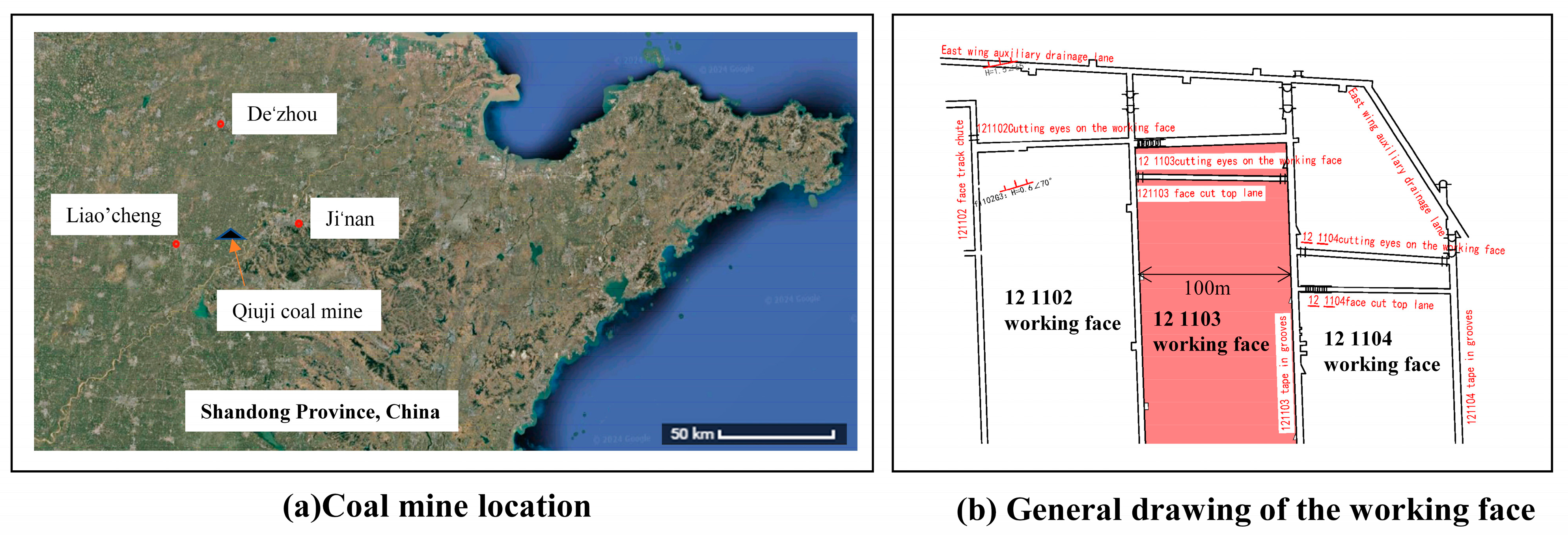
2. Project Overview
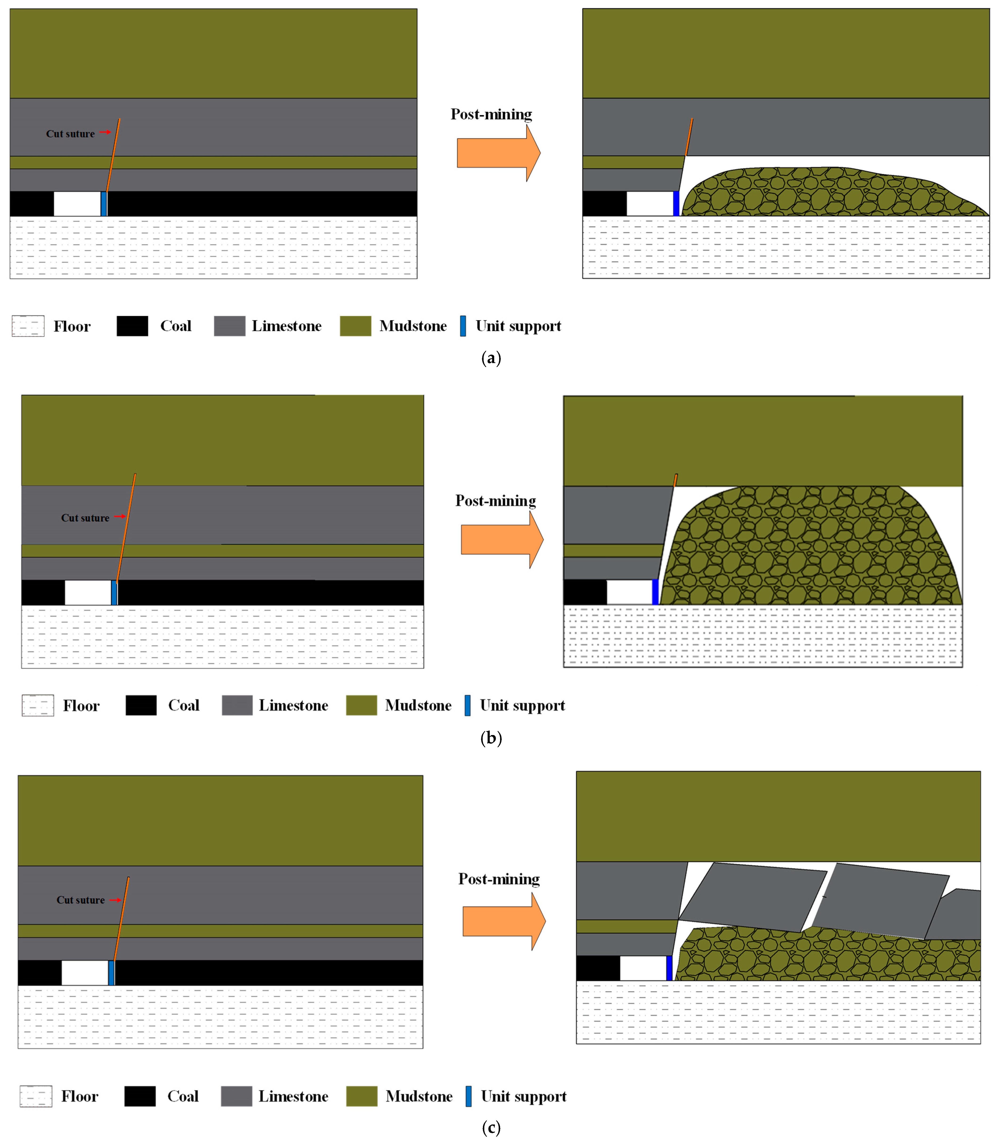
3. Theoretical Analysis of the Cutting Height of a Composite Hard Roof
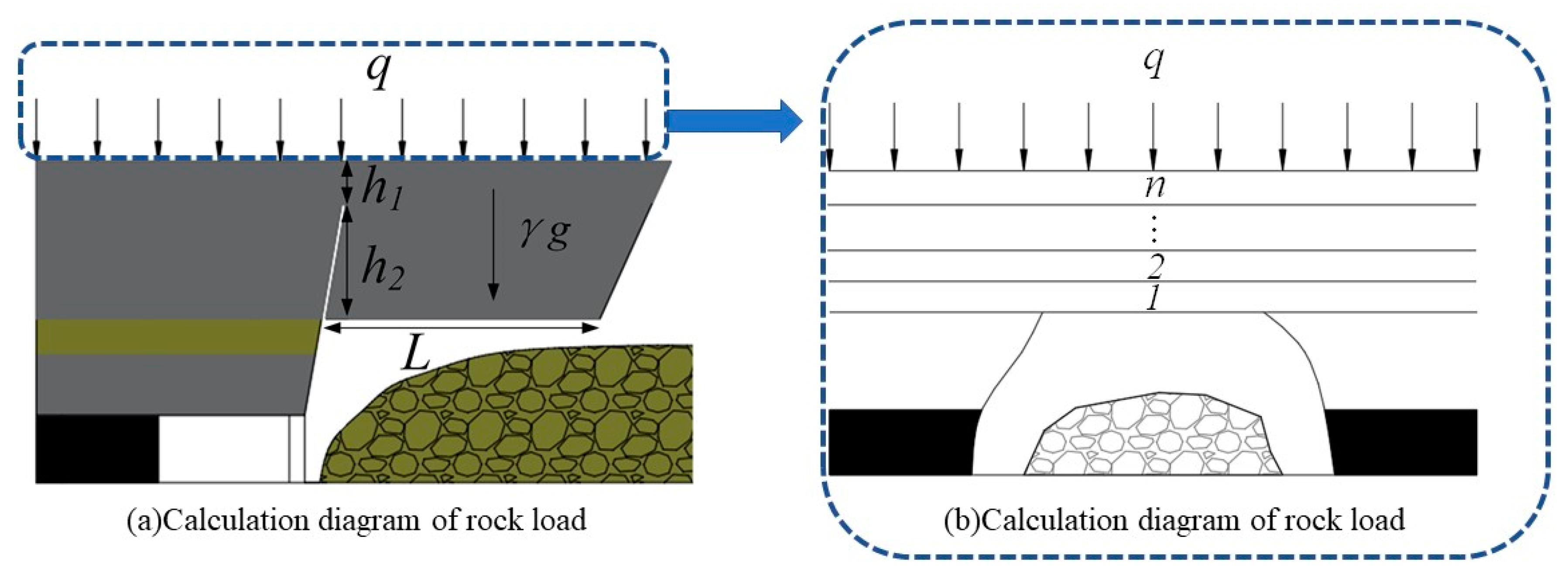
3.1. Calculation of the Overburden Load on the Roof Stratum
3.2. Derivation of the Cutting Height Calculation Formula
4. Numerical Simulation Verification
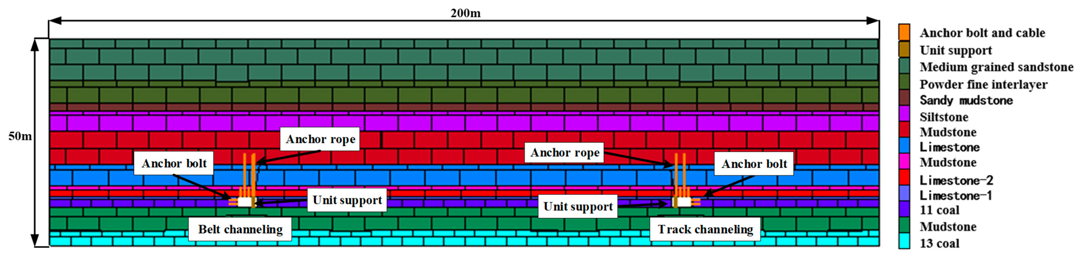
4.1. Numerical Model and Parameters
4.2. Numerical Analysis of Different Cutting Heights
- (1)
- Analysis of roof collapse conditions
- (2)
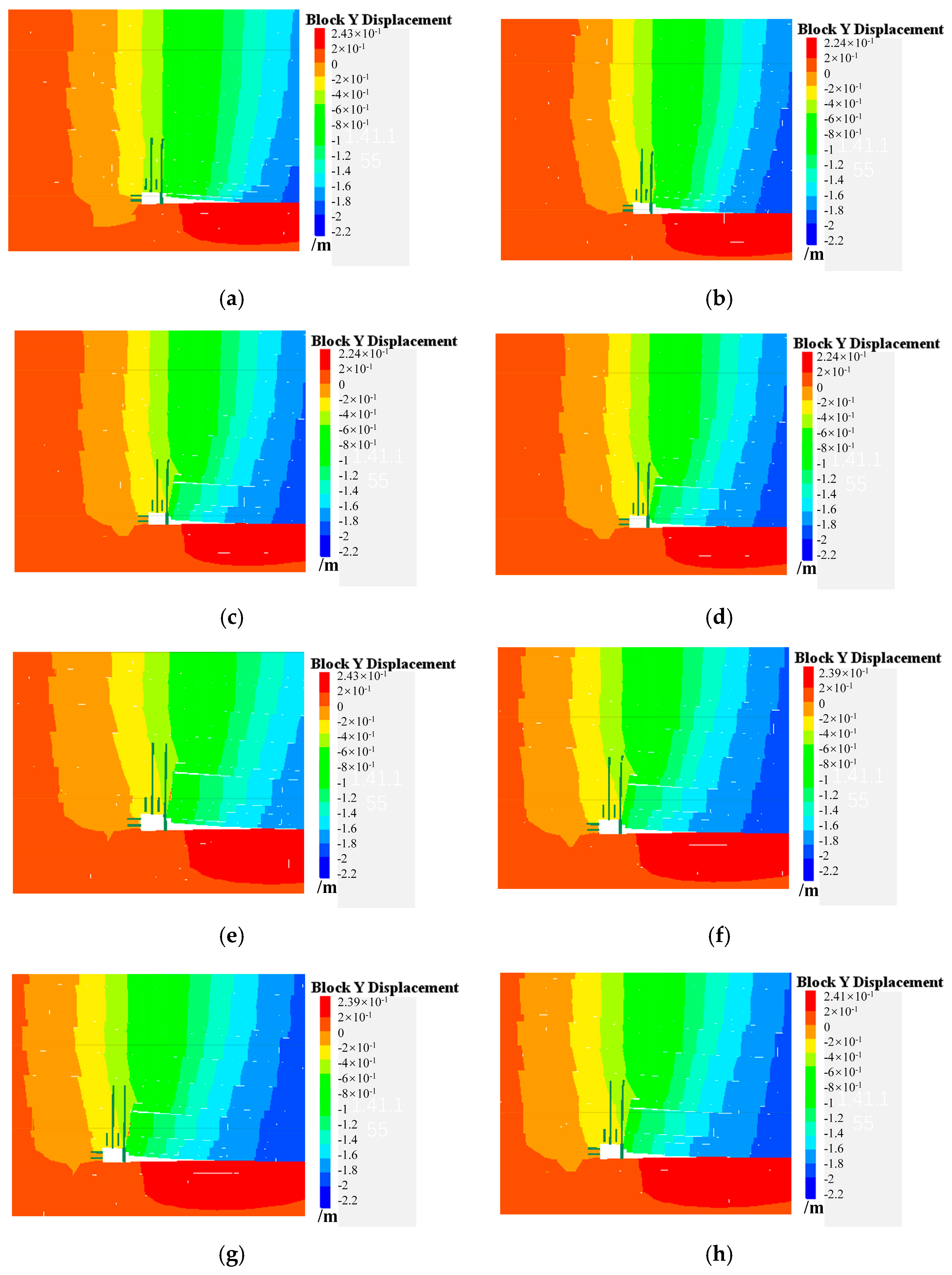
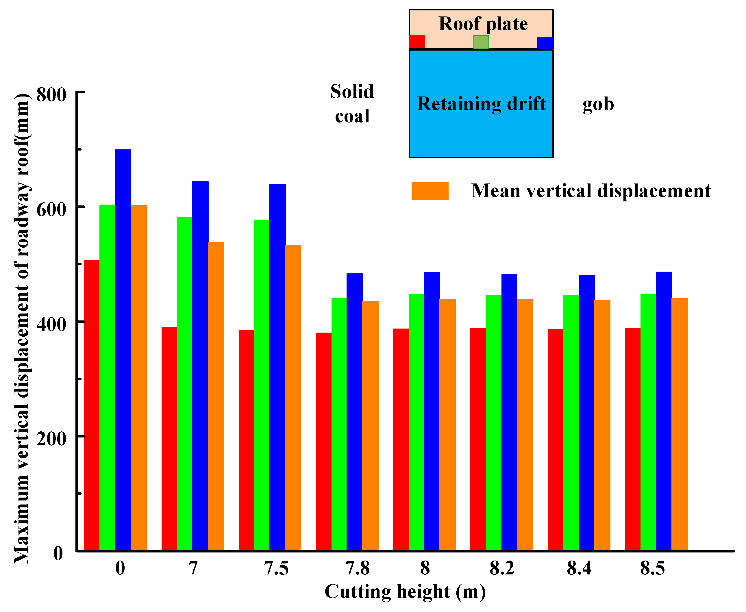
- Analysis of vertical displacement in the pillar roadway roof
- (3)
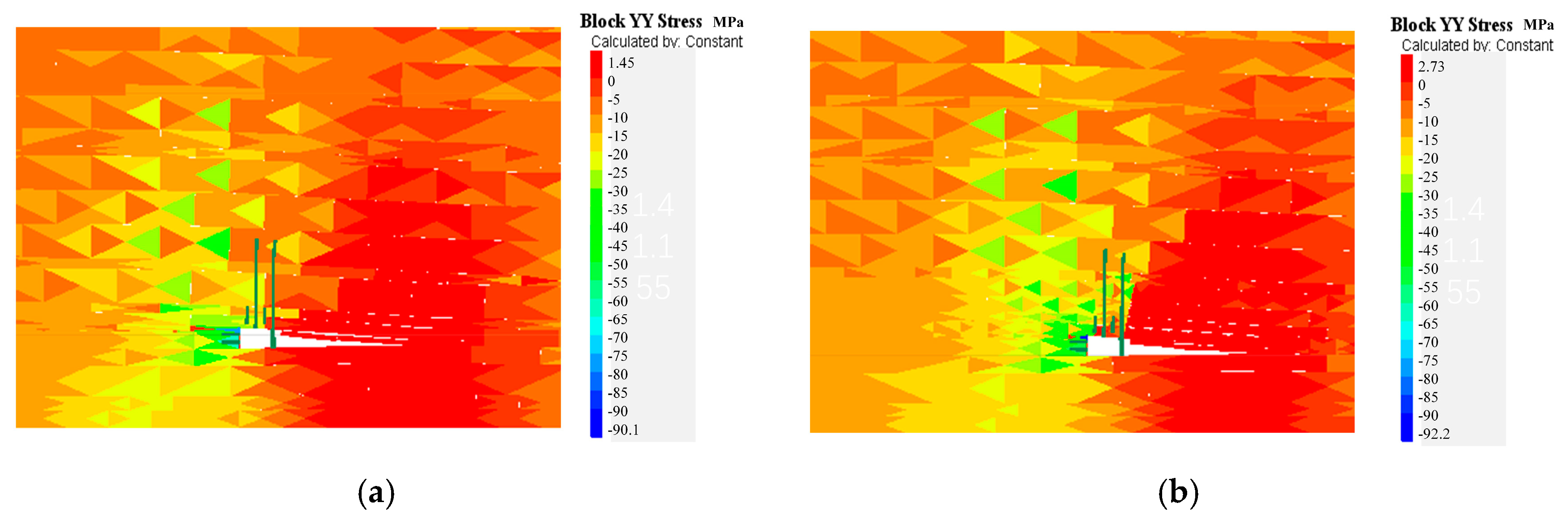
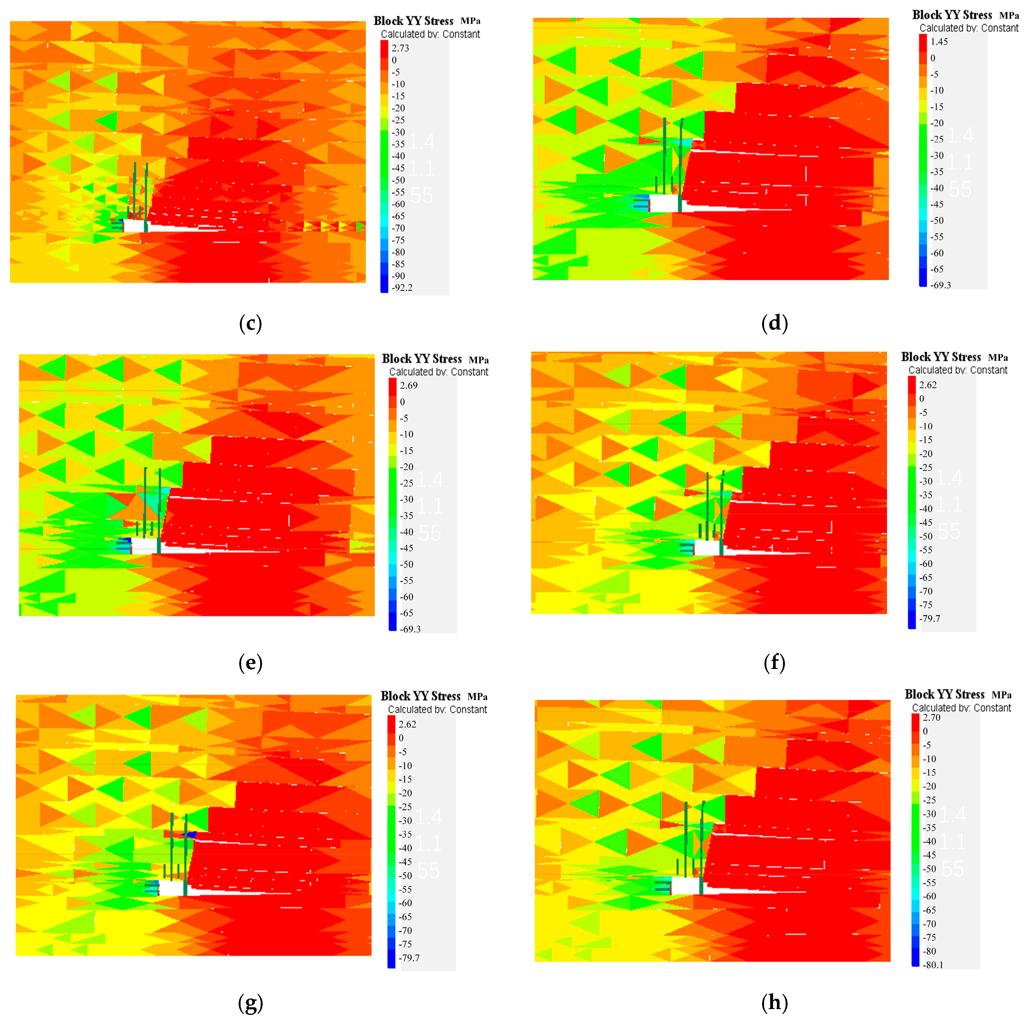
- Analysis of the vertical stress in the pillar roadway roof
5. Field Testing
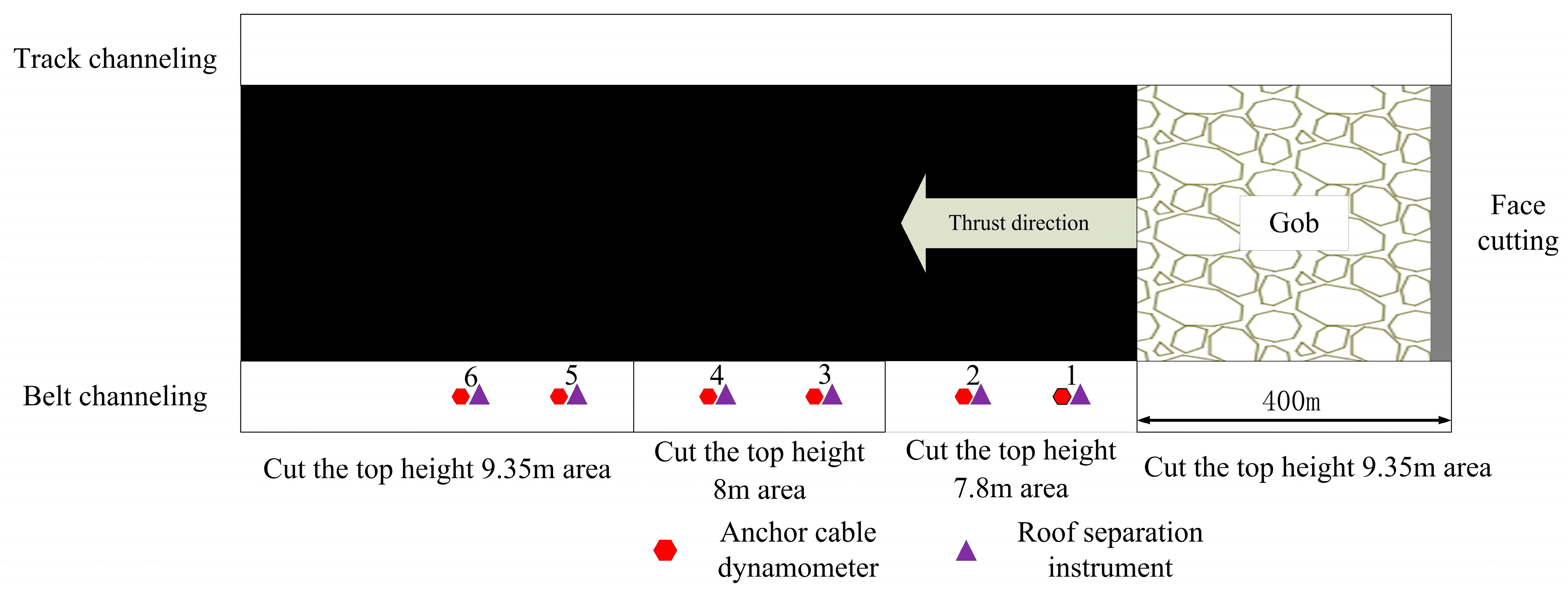
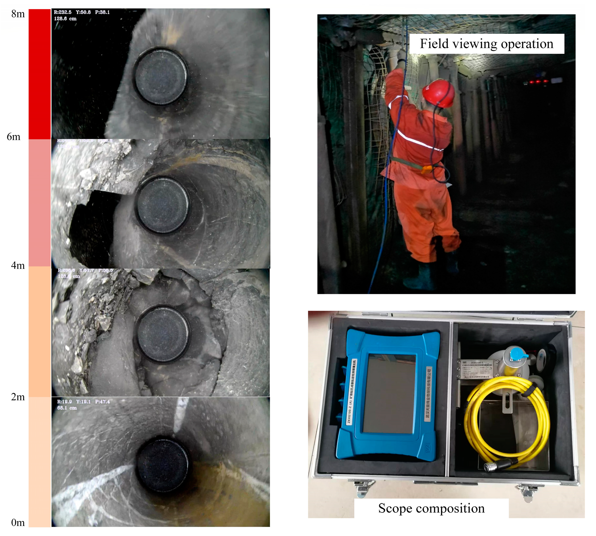
5.1. Implementation of Testing
5.2. Roof Pressure Manipulation Patterns Before and After Roof Cutting
- (1)
- The anchor cable load cells
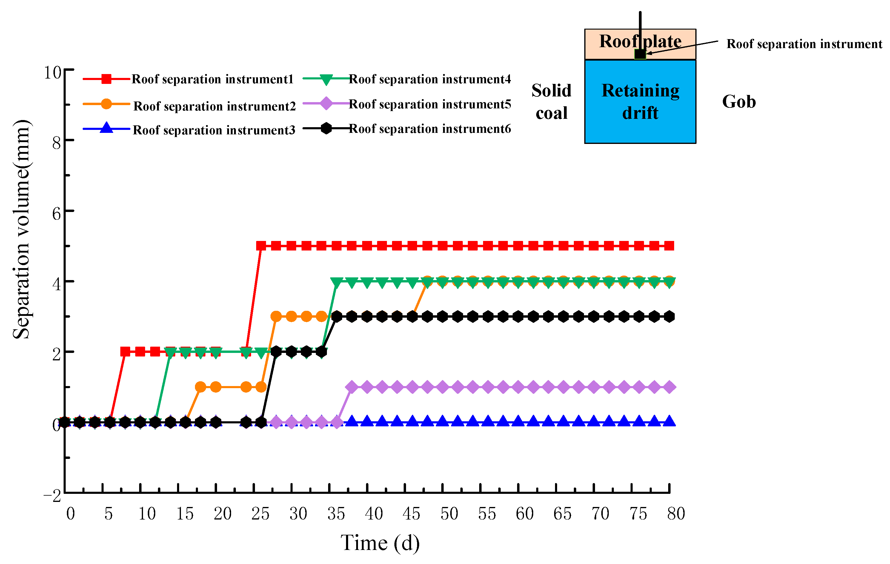
- (2)
- Roof separation instruments
5.3. Analysis of Roof Cutting Effects
5.4. Comparative Analysis of Benefits Before and After Roof Cutting Height Adjustment
6. Discussion
7. Conclusions
- (1)
- On the basis of the collapse characteristics of a goaf roof and the theory of composite beams, a lateral mechanical model of a goaf roof for a working face was constructed while considering the bulking of gangue in the goaf. By combining the theory of ultimate tensile stress and the Maxwell model, a formula for calculating the optimal cutting height of a composite hard roof was derived. Considering the geological conditions of the 12 1103 working face at the Qiuji Coal Mine, the optimal cutting height was determined to be 7.8 m.
- (2)
- UDEC 7.0 was used to simulate roof subsidence under different cutting heights, and an analysis of the numerical simulation results indicated that cutting and pressure relief had a significant effect on the stability of the composite hard roof and the suppression of floor heave in the goaf. An analysis of the roof collapse conditions, vertical displacement, and stress distribution in the roadway revealed that a cutting height of 7.8 m yields the best results for roadway stability. Further increases in the cutting height did not significantly improve the roadway stability.
- (3)
- Experiments were conducted at the 12 1103 working face with three different cutting heights: 7.8 m, 8 m, and an original height of 9.35 m. A comparative analysis of the monitoring curves from the roof anchor force gauges and the roof separation meters in the experimental section revealed that the forces acting on the roof anchors and the separation amounts were similar for all three cutting heights. The cutting height of 7.8 m ensures that the four gray layers of the basic roof collapse smoothly under their own weight. Field observations from drilling also indicated that the four gray layers of the goaf roof essentially collapsed. On the basis of the cost survey of cutting hole construction, adjusting the cutting height to 7.8 m for the 12 1103 working face could save approximately 156,000 yuan compared with the original plan while improving the construction efficiency by 15%.
Author Contributions
Funding
Data Availability Statement
Conflicts of Interest
References
- Li, X.G.; Zhang, X.Y.; Zhang, Y.; Tu, M.; Gao, Y.G.; Bu, Q.W.; Zhao, X.Y. Study on Pressure Control and Recovery Rate of Initial Mining in Super Thick Coal Seam with Hard Roof. Mining Res. Dev. 2022, 42, 20–28. [Google Scholar] [CrossRef]
- Xie, H.P. Research Progress on Mechanics and Mining Theory of Deep Rock Mass. J. China Coal Soc. 2019, 44, 1283–1305. [Google Scholar]
- Li, A.L.; Wang, S.; Gou, R.T.; Li, Z.C.; Huang, W. Research on Front Cutting Pressure Relief Technology of Hard Roof Working Face Support. Mining Res. Dev. 2024, 44, 85–91. [Google Scholar] [CrossRef]
- Wang, W.; Zheng, S.T.; Li, W.J.; Du, B.T.; Luo, A.K. Water Damage Analysis and Control Technology of Double Limestone on Top and Bottom of Huangbei Coalfield. Coal Mine Saf. 2020, 51, 93–96. [Google Scholar] [CrossRef]
- Yan, S.; Liu, T.; Bai, J.; Wu, W. Key Parameters of Gob-Side Entry Retaining in a Gassy and Thin Coal Seam with Hard Roof. Processes 2018, 6, 51. [Google Scholar] [CrossRef]
- Sun, J. Study on Failure Characteristics and Water Inrush Mechanism of Inclined Coal Seam Floor. Ph.D. Thesis, China University of Mining and Technology, Xuzhou, China, 2011. [Google Scholar]
- Wang, J.M.; Ge, J.D.; Wu, Y.H. Mechanism on Progressive Intrusion of Pressure Water under Coal Seams into Protective Aquiclude and Its Application in Prediction of Water Inrush. J. Coal Sci. Eng. 1996, 2, 9–15. [Google Scholar]
- He, M.C.; Song, Z.Q.; Wang, A.; Yang, H.H.; Qi, H.G.; Guo, Z.B. Longwall Mining Short-Wall Beam Theory and Its 110 Construction Method: The Third Mining Science and Technology Reform. Coal Sci. Technol. 2017, 1, 1–13. [Google Scholar] [CrossRef]
- Cui, J.B. Technical Research on Caving Problems of Hard Roof by Cutting Off Roof Blasting along Goaf. Master’s Thesis, Shandong University of Science and Technology, Qingdao, China, 2024. [Google Scholar]
- Su, X.S.; Wei, H.Y.; Su, Y. Research on Key Technologies of Roof Cutting and Roadway Retention under Complex Roof Conditions. Coal Sci. Technol. 2019, 47, 70–77. [Google Scholar] [CrossRef]
- Wang, F.R.; Wu, C.L.; Yao, Q.L. Instability Mechanism and Control Method of Surrounding Rock of Water-Rich Roadway Roof. Minerals 2022, 12, 1587. [Google Scholar] [CrossRef]
- Tian, C.; Wang, A.; Liu, Y.; Jia, T. Study on the Migration Law of Overlying Strata of Gob-Side Entry Retaining Formed by Roof Cutting and Pressure Releasing in the Shallow Seam. Shock Vib. 2020, 2020, 8821160. [Google Scholar] [CrossRef]
- Wang, H.; Chen, Z.; Wang, X.L.; Zhang, S. Determination and Application of Key Parameters of Hard Rock Roof Cutting and Roadway Retention. Saf. Coal Mines 2023, 54, 153–162. [Google Scholar] [CrossRef]
- Liu, Z.; Wang, J.; Zhang, C. UDEC-Based Analysis of Roof Fracture Evolution in Deep Coal Mines. Rock Mech. Rock Eng. 2021, 54, 4567–4582. [Google Scholar] [CrossRef]
- Chen, L.; Xu, H.; Zhou, W. AI-Optimized Top-Cutting Parameters for Hard Roof Control Using Genetic Algorithms. Autom. Constr. 2023, 145, 104632. [Google Scholar] [CrossRef]
- Shi, W.P.; Li, Z.Y.; Liu, C.T.; Lv, Y.W.; Zhang, H.R.; Yang, T. Research on Optimization of Key Parameters for Cutting Roadway with Thick Hard Roof in Inclined Coal Seam. Coal Sci. Technol. 2024, 52, 11–24. [Google Scholar]
- Zhang, F.; Wang, G.; Li, S. Field Validation of Numerical Models for Roof Cutting in Thick Coal Seams. J. Min. Saf. Eng. 2019, 36, 1120–1128. [Google Scholar] [CrossRef]
- Yang, X.; Mao, W.; Wang, E.; Sun, Y.; Wang, J.; He, M. Mechanism and Control Methods of Roof Deformations in Gob-Side Entry Retention by Roof Cutting under Medium-Thick Coal Seams. Geotech. Geol. Eng. 2020, 38, 265–282. [Google Scholar] [CrossRef]
- Gao, Y.B.; Yang, J.; Wang, Q.; Wang, Y.J.; He, M.C. Mechanism of Pre-Cracking and Roof Cutting in Self-Formed Roadway without Coal Pillar and Its Influence on Ore Pressure Development. J. China Coal Soc. 2019, 44, 3349–3359. [Google Scholar]
- Ma, X.G.; He, M.C.; Li, Z.; Liu, Y.X.; Yu, G.Y.; Du, H.R. Research on Key Parameters of Roof Blasting Design of Self-Forming Roadway with Composite Roof without Coal Pillar. J. China Univ. Min. Technol. 2019, 48, 236–277. [Google Scholar] [CrossRef]
- Ma, G.X. Study on Rock Crushing and Swelling Law of Deep and Thick Coal Seam under Roof Cutting and Unloading. Coal Eng. 2019, 51, 118–121. [Google Scholar]
- Ma, Q.; Zhang, Y.; Li, Z.; Song, G.; Zheng, Y. The Roadway Layout and Control Technology of Pillar-Free Mining of Soft Coal Seams in High Gassy Mines. Processes 2022, 10, 1784. [Google Scholar] [CrossRef]
- Terzaghi, K.; Peck, R.B.; Mesri, G. Soil Mechanics in Engineering Practice, 3rd ed.; Wiley: New York, NY, USA, 1996. [Google Scholar]
- Ma, L.; Xing, L.; Liu, C.; Cui, T.; Qiao, X.; Miao, W.; Kong, P. Research on the Instability Mechanism and Control Technology of Gob-Side Entry in Deep Mines with Soft Rock. Buildings 2025, 15, 19. [Google Scholar] [CrossRef]
- Findley, W.N.; Lai, J.S.; Onaran, K. Creep and Relaxation of Nonlinear Viscoelastic Materials; Dover: Mineola, NY, USA, 1976. [Google Scholar]


| Author | Method | Key Findings | Limitations | Applicability |
|---|---|---|---|---|
| Su et al. [10] | Stress-structure model | Cut height affects immediate roof movement | Ignored dynamic geological changes | Reserved roadways |
| Wang et al. [11] | Mechanical model | Top-cutting height affects goaf filling | Ignored dynamic loading | Homogeneous strata |
| Tian et al. [12] | Mechanical model | Increased height reduces coal wall stress | Assumed linear roof behavior | Hard roofs |
| Shi et al. [16] | PFC2D simulation | Log correlation: height vs. pressure relief | Limited to 2D analysis | Thin coal seams |
| Yang et al. [18] | Field tests + simulation | Optimal height for thick seams | Required extensive calibration | Guandi Mine conditions |
| Liu et al. [14] | UDEC simulation | Captures multi-scale fracture propagation | High computational cost | Deep, fractured roofs |
| Chen et al. [15] | AI optimization | Adaptive parameter selection | Requires large training data | High-gas, soft seams |
| Zhang et al. [17] | Field monitoring | Validates numerical models | Site-specific constraints | Thick coal seams |
| Roof and Floor Terminology | Rock Types | Thickness/(m) | Classification of Roof and Floor Strata | Mohs Hardness Scale f | Porosity (%) | Compressive Strength (MPa) |
|---|---|---|---|---|---|---|
| Direct Roof | Limestone | 2.01 | IV | 13.557 | 6 | 135.57 |
| Direct Floor | Mudstone | 5.56 | III | 1.07 | 8.87 | 10.7 |
| Rock Strata | Lithology | Volume Force γi/(kN/m3) | Layer Thickness hi/(m) | Elastic Modulus Ei/(MPa) |
|---|---|---|---|---|
| 1 | Limestone | 26 | 5.13 | 1.3 × 10⁴ |
| 2 | Mudstone | 22.5 | 7.97 | 1.1 × 10⁴ |
| 3 | Siltstone | 25.5 | 5.0 | 1.9 × 10⁴ |
| 4 | Silty Mudstone | 21.5 | 2.01 | 1.5 × 10⁴ |
| Name of the Working Face | Maximum Lateral Cantilever Length in Uncaved Area Behind Frame/(m) |
|---|---|
| Working Face 11 1107 | 4.7 |
| Working Face 11 1108 | 4.4 |
| Working Face 12 1101 | 4.6 |
| Working Face 12 1103 | 4.3 |
| Name | Density (kg/m3) | Normal Stiffness (GPa) | Shear Stiffness (GPa) | Cohesive Force (MPa) | Friction Angle (°) | Tensile Strength (MPa) |
|---|---|---|---|---|---|---|
| Silt-Clay Interbedding | 2540 | 10.23 | 3.43 | 2.96 | 35 | 3.26 |
| Silty Mudstone | 2240 | 3.27 | 1.43 | 1.52 | 26 | 1.28 |
| Siltstone | 2550 | 7.55 | 2.94 | 2.34 | 35 | 3.47 |
| Mudstone | 2250 | 4.59 | 1.79 | 1.47 | 25 | 1.54 |
| Limestone | 2600 | 16.84 | 8.12 | 3.02 | 35 | 3.16 |
| Mudstone | 2250 | 4.59 | 1.79 | 1.47 | 25 | 1.54 |
| Limestone | 2600 | 16.84 | 8.12 | 3.02 | 35 | 3.16 |
| Type 11 Coal | 1420 | 2.45 | 0.91 | 1.50 | 28 | 1.14 |
| Mudstone | 2250 | 4.59 | 1.79 | 1.47 | 25 | 1.54 |
| Type 13 Coal | 1420 | 2.45 | 0.91 | 1.50 | 28 | 1.14 |
| Parameter | Original (9.35 m) | Optimized (7.8 m) | Reduction |
|---|---|---|---|
| Drilling depth per hole | 9.5 m | 8.0 m | 15.8% |
| Cost per meter | 150 yuan/m | 127.5 yuan/m | 15% |
| Annual maintenance cost | 600,000 yuan | 420,000 yuan | 180,000 yuan |
Disclaimer/Publisher’s Note: The statements, opinions and data contained in all publications are solely those of the individual author(s) and contributor(s) and not of MDPI and/or the editor(s). MDPI and/or the editor(s) disclaim responsibility for any injury to people or property resulting from any ideas, methods, instructions or products referred to in the content. |
© 2025 by the authors. Licensee MDPI, Basel, Switzerland. This article is an open access article distributed under the terms and conditions of the Creative Commons Attribution (CC BY) license (https://creativecommons.org/licenses/by/4.0/).
Share and Cite
Wu, J.; Bai, D.; Zhang, Y.; Zhu, Q.; Liu, P.; Chen, Q.; Zhang, Y. Detailed Analysis of the Cutoff Height in Composite Hard Rock Roofs Along Goaf Roadways. Processes 2025, 13, 838. https://doi.org/10.3390/pr13030838
Wu J, Bai D, Zhang Y, Zhu Q, Liu P, Chen Q, Zhang Y. Detailed Analysis of the Cutoff Height in Composite Hard Rock Roofs Along Goaf Roadways. Processes. 2025; 13(3):838. https://doi.org/10.3390/pr13030838
Chicago/Turabian StyleWu, Jun, Dongdong Bai, Yong Zhang, Qingwen Zhu, Peiyue Liu, Qingyu Chen, and Yuxuan Zhang. 2025. "Detailed Analysis of the Cutoff Height in Composite Hard Rock Roofs Along Goaf Roadways" Processes 13, no. 3: 838. https://doi.org/10.3390/pr13030838
APA StyleWu, J., Bai, D., Zhang, Y., Zhu, Q., Liu, P., Chen, Q., & Zhang, Y. (2025). Detailed Analysis of the Cutoff Height in Composite Hard Rock Roofs Along Goaf Roadways. Processes, 13(3), 838. https://doi.org/10.3390/pr13030838