1. Introduction
With the strengthening of global environmental awareness and the increasingly serious energy crisis, countries around the world have introduced strict emission regulations and energy efficiency standards to reduce the environmental pollution and energy consumption of internal combustion engines. In China, with the introduction of the National VI emission standard, the emission requirements of diesel engines are higher, and the manufacturers of internal combustion engines are constantly adjusting the performance of internal combustion engine products to meet the requirements of emission regulations [
1]. In recent years, the country has vigorously developed agricultural mechanization and small power generation equipment intelligence, and the state has invested much manpower and material resources, as well as policies to implement various plans. The National Agricultural Mechanization Development “14th Five-Year Plan” [
2] clearly put forward the improvement of the level of agricultural machinery intelligence, and promoted efficient, safe, and environmentally friendly agricultural production. The above policy opens up a broad market and policy conditions for the research on, and application of, single-cylinder diesel engine speed control systems.
The single-cylinder diesel engine is widely used in agricultural machinery, small power generation equipment [
3], and ship propulsion and other fields. The stability of the speed control of this engine has a vital impact on its operational efficiency and reliability in the whole system; therefore, improving the dynamic and static performance of the speed control system of the single-cylinder diesel engine is one of the key points in the research on the control of its power mechanical system.
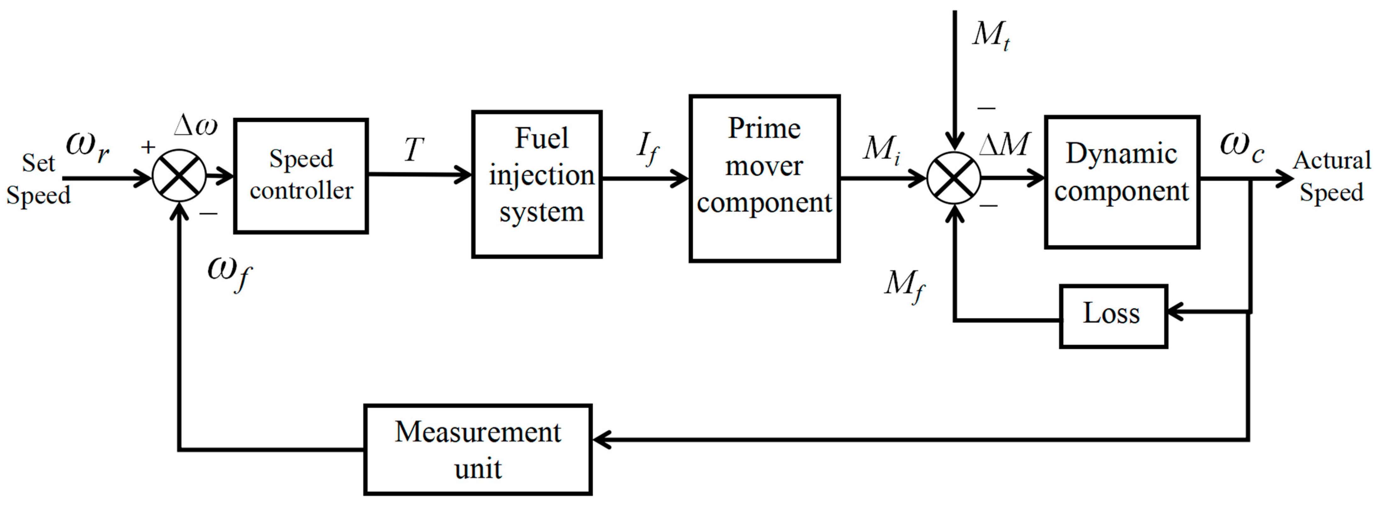
Figure 1 shows the complexity of the control system of the diesel engine, from the generation of the speed signal to the adjustment of the control system, the injection of fuel, the combustion of the cylinder to do work, and then to synchronization of the output to produce the crankshaft torque and thus the output of power. This is a very complex mechanical body involving a variety of disciplines such as fluid dynamics, combinatorics, mechanical principles, and control theory. This diesel engine has very strong nonlinearities, response hysteresis, and coupling phenomena [
4].
Because the diesel engine system has relatively complex time-varying nonlinear and multi-input and multi-output characteristics, in the whole process of diesel engine operation, the sudden changes in load, mechanical wear, and other problems often make the control performance problematic [
5]; at the same time, in the diesel engine, after a long period of time, the mechanical wear and tear makes the system dynamic characteristics change, which will also increase the difficulty of control. These factors will trigger the system’s dynamic and static performance deterioration, affecting the overall stability of the system as well as the operating efficiency [
6], so the use of simple PID control of the diesel engine speed may not be ideal for performance improvement. Especially regarding diesel engine load changes and other complex operating conditions, some parameters in the PID controller cannot be adapted to the changes in the control requirements, and system performance is easily and obviously reduced. Therefore, how to find a suitable diesel engine speed control system is of particular significance.
In response to the above problems of control performance optimization, many scholars have proposed and used a fuzzy PID controller combining fuzzy logic and PID in the literature, and achieved certain practical results in some engineering fields: reference [
7] proposed a fuzzy PID-based control method to solve the problem of a rice-planting robotic arm being affected by external disturbances, which affected the displacement tracking of the hydraulic rice-planting system, leading to the problem of reduced output accuracy. The method improves the step response time of the system by 56%. By using fuzzy PID control, the system is able to solve the problems related to nonlinearity and low control accuracy, thus improving its stability and dynamic performance. Reference [
8] describes an enhanced fuzzy PID control system based on a grey model that adjusts the residuals using an improved gated recursive unit (GM-IPSO-GRU) based on particle swarm optimization. In addition, the system optimizes the control parameters by using the Improved Gray Wolf Optimization (IGWO) algorithm. Although the system overcomes the problems of nonlinearity, time variation, and time delay, the response speed and stability of the system still need to be improved. Compared with the traditional PID controller, the fuzzy PID controller can better deal with nonlinearity, uncertainty, and ambiguity in complex systems, and it can automatically adjust the parameters without manual adjustment, thus saving the adjustment time and adjustment cost [
9].
However, the fuzzy PID control methodology still faces limitations such as reliance on manual parameter configuration, absence of self-adaptive adjustment mechanisms, and suboptimal performance when applied to complex systems with nonlinear and time-varying characteristics. Specifically, these constraints may lead to convergence to local optima and exhibit sluggish response dynamics in practical implementations. In order to facilitate the automatic optimization of control parameters to improve the performance, in recent years, global optimization algorithms such as Particle Swarm Optimization (PSO) have become an effective method to optimize the fuzzy PID parameters. PSO simulates the search of particles in the solution space, and is able to search for optimal scaling factors and quantization factors in the multidimensional space, thus significantly improving the control performance of fuzzy PID control. In terms of agricultural machinery, reference [
10] used an IPSO-optimized fuzzy PID controller to implement adaptive head trimming for a cabbage harvester and verified the control accuracy of ±3 mm of gripping gap in a field test. However, this work failed to account for the real-time effects of dynamic changes in crop size on the control parameters. Similarly, reference [
11] developed a dual closed-loop seeding system with radar speed measurement that achieved a field pass rate of 93.99% for corn seeding, but terrain-induced speed measurement errors still constrained the uniformity of seeding spacing. In vehicle engineering, reference [
12] proposed a PSO fuzzy PID controller for in-wheel brushless DC motors, which can reduce the tire slip rate by 12%. Reference [
13] pioneered a PSO-Fuzzy-PID controller for a greenhouse glass cleaner, which achieved an inter-wheel speed difference of 0.086 deg/s through Adams–Matlab co-simulation. For wind energy applications, reference [
14] combined fuzzy inverse stepping sliding mode control with MOPSO to improve the power extraction efficiency by 18.7%, but the mechanical load fluctuation under sudden change of wind speed was still not optimal. For grid frequency regulation, reference [
15] innovatively integrated supercapacitors and redox flow batteries to suppress system oscillations by 64%.
In the field of robotics and motor control, in reference [
16], three different PSO algorithms based on cost function were used to optimize the fuzzy logic controller parameters of a two-degree-of-freedom planar robot, and the improved controller was derived by changing the model parameters and the reference trajectory, varying the model parameters, adding white noise for testing, and testing the robustness of the adjusted controller to provide valuable test method improvement results. Reference [
17] proposed a two-dimensional fuzzy fractional PID controller to cope with a large number of parameters in a fractional order controller and designed a multi-objective PSO algorithm capable of determining the system parameters to optimize the parameter determination process. Reference [
18] proposed a Genetic Particle Swarm Optimization (GAPSO) strategy for optimizing fuzzy PID control parameters for motor control. The method combines a genetic algorithm and particle swarm optimization through a genetic screening method to optimize the initial values of quantization factor, scale factor, and eigenfunction, which provides a new method for the adjustment of fuzzy PID control parameters.
Like fuzzy PID control, PSO-optimized fuzzy control is also widely used in many temperature control systems. The heat transfer process in temperature control is a typical nonlinear process, which is affected by factors such as the heat source, heat capacity, environmental conditions, etc. For the research object involved in this study, the system diesel engine speed control is affected by nonlinear factors such as engine load, fuel supply, and mechanical friction, and both systems are nonlinear systems. The application of the literature [
19] can optimize the proportional weight coefficients of the fuzzy PID controller in the temperature control system of the resistance furnace, and this method better improves the key control indexes such as overshoot and steady-state error of this control system, and improves the quality and stability of temperature control. Reference [
20] reduced the temperature response time of a PEM fuel cell under step disturbance to 2.3 s; reference [
21] reduced the failure rate of an air handling unit by 64% through NARMAX modeling. While these studies validate the robustness of the PSO fuzzy PID architecture, few studies have fully utilized the state of the thermodynamic system for temperature estimation.
Currently, there are two common limitations in engineering research for PSO fuzzy PID algorithms: firstly, the problems of sensor error and noise; and secondly, the lack of real-time prediction of changes in environmental dynamics (e.g., gusts of wind, road friction, and crop morphology, etc.). The use of filters can effectively improve the above problems and enhance the control accuracy, while the speed control of diesel engines has certain nonlinearities, load perturbations, fuel supply issues, etc., that will affect the dynamic response of the speed, and the traditional Kalman filter (KF) is only applicable to linear systems, and is not able to solve the nonlinear problems. The Untraceable Kalman Filter (UKF), as an advanced filtering method, can provide high-precision state estimation in complex nonlinear systems and effectively suppress noise disturbances. Reference [
22] describes a novel algorithm to simultaneously estimate the state of charge (SOC) and state of health (SOH) using a strongly tracking dual adaptive extended Kalman filter (ST-DAEKF). To enhance the tracking capability, an attenuation factor is incorporated in the method and an adaptive filter is used to dynamically adjust the noise parameters of the system. This approach is designed to mitigate the problems arising from large estimation errors in the SOC and SOH. Reference [
23] designed an irrigation system based on Kalman filter PID controller using IAE, ISE, and cumulative ITAE for simulation. By modeling the dynamics using historical real-time data, the KF reduces the sensor output noise and improves the estimation accuracy. Reference [
24] presents a hybrid optimization model that integrates an adaptive neuro-fuzzy inference system (ANFIS), a recursive Kalman filter, and neural wavelets for wind power prediction driven by a doubly-fed induction generator, which exhibits excellent performance. Reference [
25] designed an algorithm for vehicle traveling state estimation by applying an adaptive Kalman filter combined with a fuzzy PID controller, demonstrating the accuracy of the Kalman filter in state estimation. Reference [
26] optimized the PID gain of a hydraulic servo system using a genetic algorithm and combined it with Kalman filtering to reduce the external disturbances and amplitude fluctuations, and verified the effectiveness of the method in hydraulic servo systems. Reference [
27] developed an observer for diagnosis and fault tolerant control of aging SCR (Selective Catalytic Reduction) systems using UKF, further highlighting the effectiveness of the filtering approach in fault detection and system management. Reference [
28] proposed a temperature control system based on Kalman filtering fuzzy PID design. From the experimental results, the algorithm has short tuning time and almost zero overshoot, but its adaptability under complex operating conditions has not yet been clearly addressed. The current research results show that traceless Kalman filtering is an advanced filtering method that can provide high-precision state estimation in complex nonlinear systems and effectively suppress noise interference. If UKF is combined with PSO fuzzy PID control, it is expected to further improve the estimation accuracy and control performance of the system, and overcome the limitations of PID control and fuzzy PID control under noise and disturbances.
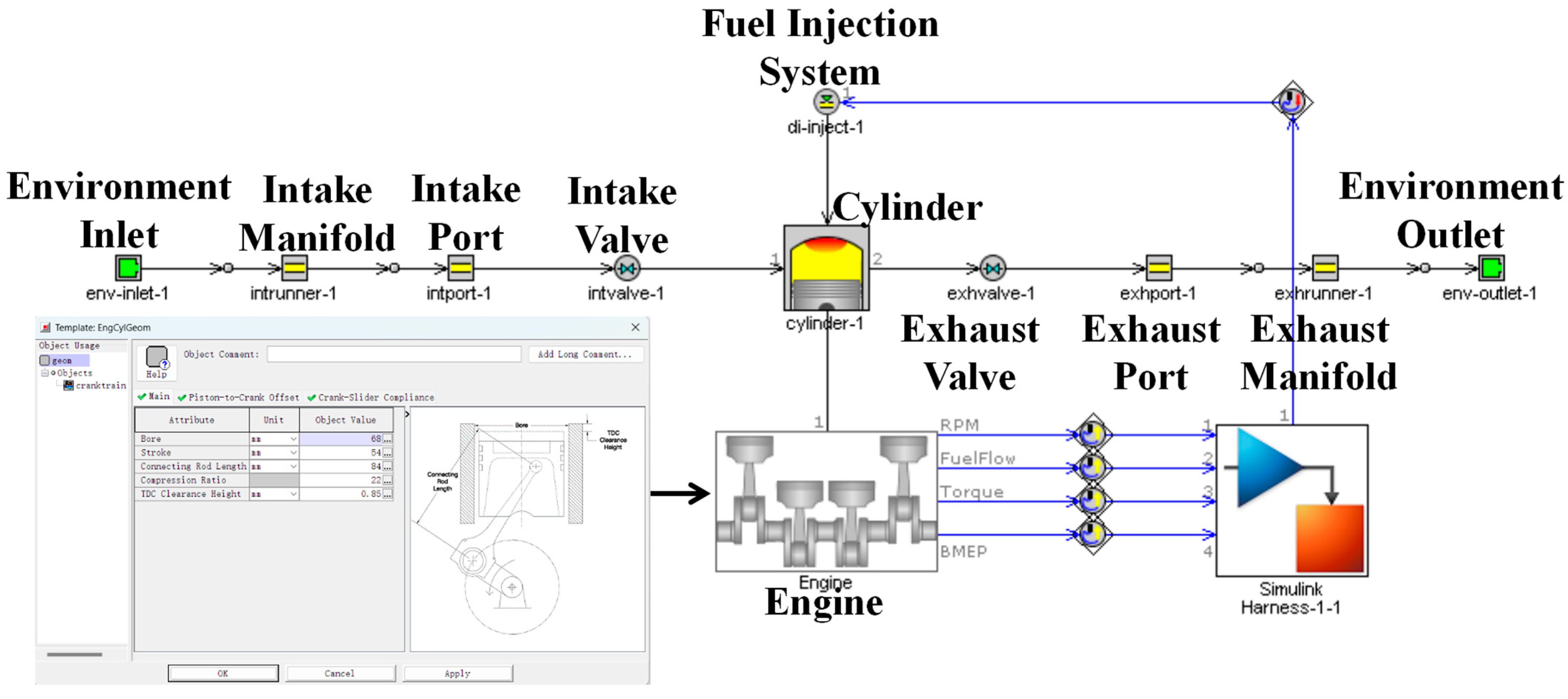
In response to the above research analysis, a PSO fuzzy PID control strategy for diesel engine speed optimization based on UKF filtered data is proposed. The strategy provides accurate estimation of diesel engine speed through UKF, effectively eliminating the influence of measurement noise and process noise on speed accuracy. Based on the accurate rotational speed data, the parameters of the fuzzy PID controller are optimized in combination with the PSO algorithm to achieve more accurate and robust control performance. We established a dynamic model of a single-cylinder diesel engine and built a simulation model of the algorithm in Matlab/Simulink (R2022b). By comparing it with four algorithms such as traditional PID control, we analyzed the optimization improvement of the proposed algorithm in terms of response time, overshooting amount, and steady-state error. Meanwhile, in the extension work of this study, the GT-POWER model of a 168 F single-cylinder diesel engine is built, and the cylinder pressure and fuel consumption parameters are verified through bench experiments, which lays the foundation for future joint simulation studies.
3. Methods
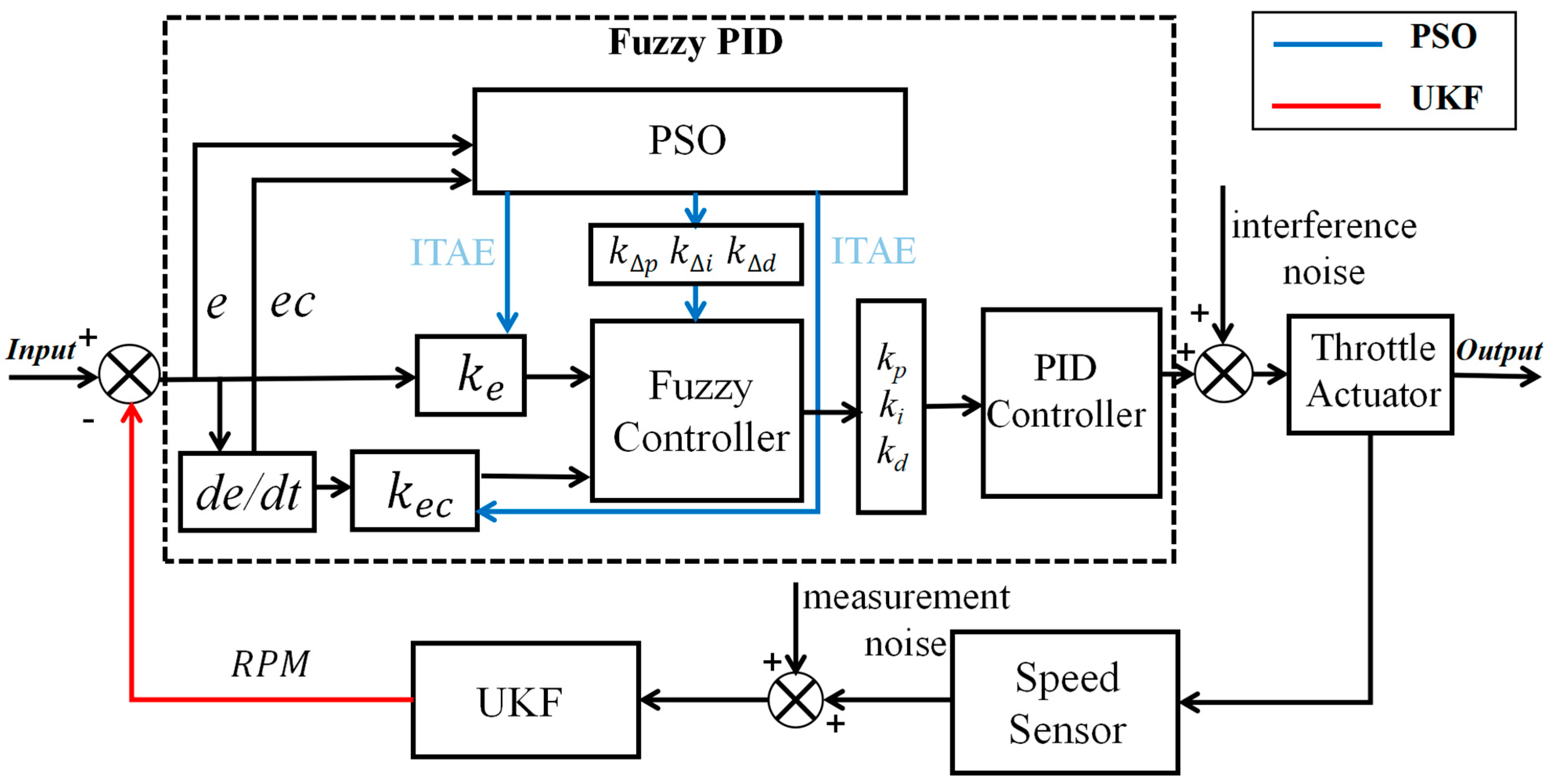
In order to further improve the static and dynamic performance of the diesel engine speed control system, this paper proposes an improved method that combines the untraceable Kalman filter with the particle swarm optimized fuzzy PID control technique. The speed sensor data received by the untraceable Kalman filter (UKF) accurately estimates the diesel engine speed through information such as torque and fuel injection, while filtering for the interference of Hall sensor measurement noise and process noise in the control system, and provides accurate speed data for the control system. Fuzzy PID control utilizes fuzzy logic to change the
,
,
of the PID controller, effectively overcoming the shortcomings of the traditional PID method of poor control performance under nonlinear, time-varying, and complex operating conditions. At the same time, a PSO optimization algorithm is introduced to globally optimize the proportional factor and quantization factor in the fuzzy controller. By simulating the process of particle swarm searching for the optimal solution, the PSO algorithm realizes the indirect dynamic adjustment of the PID parameters, which further enhances the adaptability and robustness of the controller. By combining the accurate state estimation of the UKF with PSO-optimized fuzzy PID control, not only can the control parameters be precisely adjusted, but also can effectively deal with disturbances and uncertainties to ensure that the diesel engine maintains accurate speed control under different operating conditions. The technical flow chart of this paper is shown in
Figure 8, and the principle of the collection of the UKF and PSO Fuzzy PID controllers is shown in
Figure 9. The design and implementation methods of this control strategy are described in detail in the following section.
3.1. Unscented Kalman Filter
The Kalman filter is optimal for linear systems with Gaussian noise, but the noise in diesel engines is high and nonlinear, with time-varying dynamics and coupled disturbances. In the environment of a diesel generator system, diesel engines experience significant interference and noise. To improve the system’s control performance, this study uses UKF filtering to control the impact of disturbances and measurement noise on the system. The UKF filtering method approximates the nonlinear distribution using a sampling strategy, where the probability distribution of the nonlinear function is approximated. Based on the Unscented Transform, the Unscented Kalman Filtering framework is employed, with deterministic sampling as the form of sampling, unlike the random sampling in Particle Filtering, thus avoiding the particle degradation issue. It outperforms the Extended Kalman Filter and does not require the calculation of the Jacobian matrix [
33].
The nonlinear system model in this study is converted into a discrete model, and its state and observation equations are
where
is the system state vector, where
represents the diesel engine speed and
is the system load.
is the state transition function, describing the dynamic evolution of the diesel engine from time step to time step .
The rotational inertia
governs the speed response to net torque:
where
depends nonlinearly on fuel injection quantity and combustion efficiency, and
is the control input, which includes factors such as fuel injection quantity, throttle position, etc.
represents speed-dependent friction losses, and
is the process noise for speed, assumed to be Gaussian noise with covariance
is the observation vector, which here represents the actual measured engine speed. is the observation function, describing the system’s measurement process. is the observation noise, assumed to be Gaussian noise with covariance .
Load torque
evolves as
where
models external load variations, and
captures unmodeled disturbances.
The observation equation
directly measures the engine speed, with
representing Hall sensor quantization noise (
). Sensor noise is calibrated using the root mean square error (RMSE):
where
is the
rotational speed sampling point.
The calibration method is to calculate the standard deviation by recording 1000 rpm sampling points under the steady-state error condition, and the typical value is taken as ±50 rpm, which corresponds to FS.
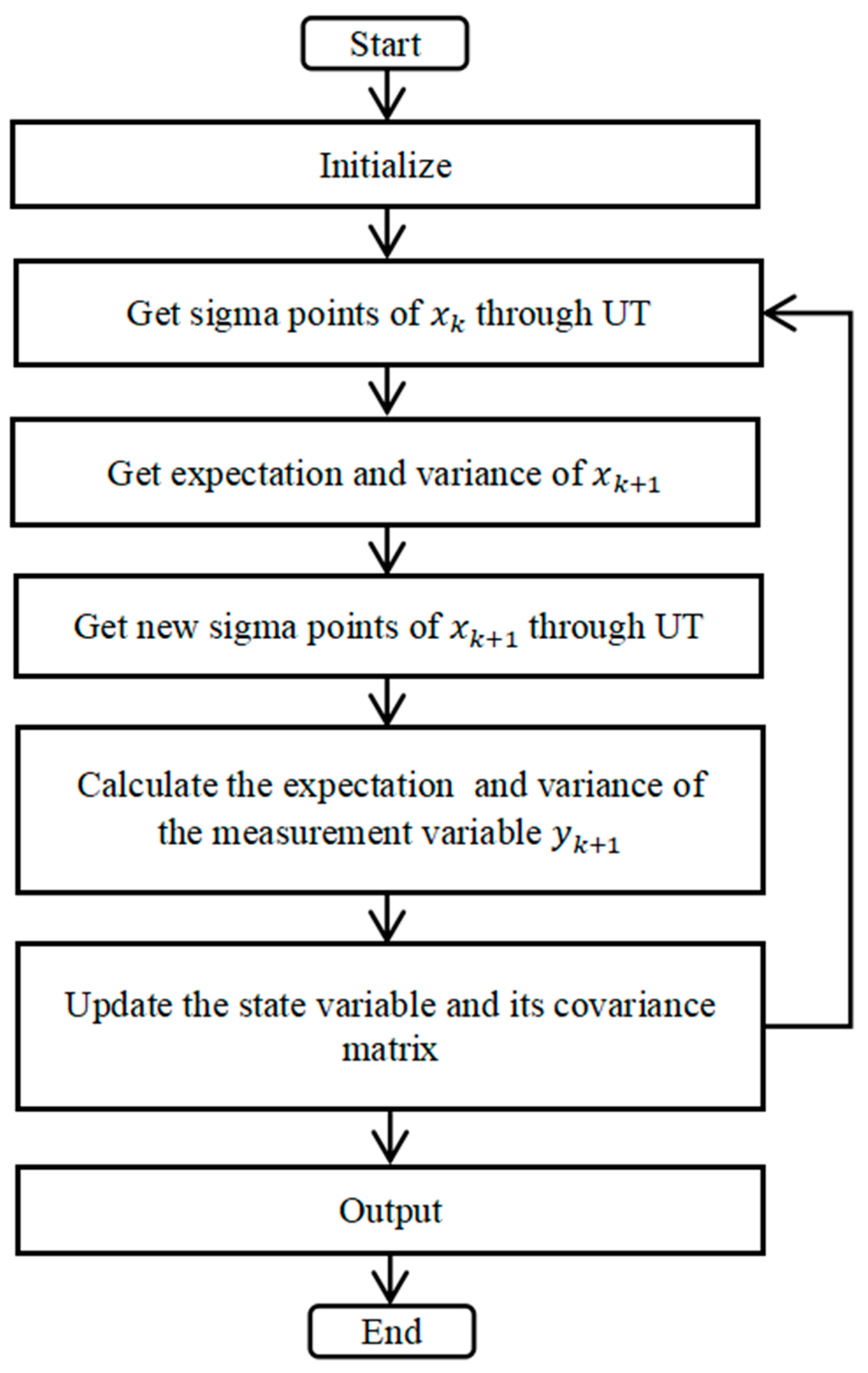
The flowchart of the UKF is shown in
Figure 10.
Calculate the Sigma sample points of the input variable within each sampling period
:
where
, where the parameter
;
is a secondary sampling factor;
represents the
-th row or column of the matrix square root.
Step 2: For each sigma point, perform the nonlinear transformation and then take the average to update the state.
Then compute predicted mean
and covariance
:
where
,
,
,
; where
is a higher-order error sampling factor. The optimal value of
β when the error is Gaussian distributed is 2.
Step 3: Measurement update.
Step 4: Update the state estimate using Kalman gain
.
Process noise accounts for mechanical nonlinearities (gear backlash, friction hysteresis) and electromagnetic interference, approximated as Gaussian white noise. Measurement noise is calibrated via RMSE.
Above is the processing of the UKF algorithm for filtering and estimation of diesel engine speed. The algorithm uses the state augmentation method [
34]. After determining the process noise covariance matrix
, the measurement noise covariance matrix
, and the initial filter values
and
, the state estimate
at time
can be obtained from the computed measurement value
using the above calculation formulas.
In order to verify the noise reduction effect of the unscaled Kalman filter on the speed measurement data, we use Matlab (R2022b) to simulate the diesel engine speed step from 1500 rpm to 1000 rpm, and the results are shown in
Figure 11.
It can be shown in
Table 4 that the UKF can effectively suppress the measurement noise and provide a more accurate estimation of the diesel engine speed.
Under environmental disturbances, when using fuzzy PID control alone, the system often fails to avoid fluctuations and struggles to effectively handle control disturbances and eliminate measurement noise, resulting in suboptimal control performance. Given the significant advantage of the Unscented Kalman Filter in suppressing and eliminating noise, this paper proposes combining the Unscented Kalman Filter with a Particle Swarm Optimization fuzzy PID controller for joint system control.
3.2. Fuzzy PID Controller
In the single-cylinder diesel engine speed control system, the fuzzy PID control algorithm is used to adjust the fuel supply of the diesel engine in real time to ensure speed stability and response speed. When the working environment of the diesel engine is more complex and the load change is too large, due to the fluctuation of fuel quality, the change in ambient temperature and other factors will cause engine speed fluctuation, and the PID control algorithm is hard to adapt to the complex diesel engine operating conditions, which are prone to overshooting, oscillating, or excessive adjustment time [
35]. Consequently, we selected the fuzzy PID control algorithm in this study, and the PID parameters were adjusted according to the changes in the operating conditions in which the diesel engine was located.
When the diesel engine load increases abruptly, the system generates a large deviation; at this time, the fuzzy controller recognizes this condition and immediately increases its proportionality coefficient and integral coefficient , increasing the response speed of the system and reducing the steady-state error. Conversely, when the system tends towards stability, the fuzzy controller will gradually decrease the proportional coefficient and increase the integral coefficient to eliminate residual deviations, thus ensuring stable engine speed under various operating conditions.
Accurate real-time data acquisition and processing are fundamental to ensuring control precision. The current actual speed of the diesel engine is obtained through sensors, and these data are filtered to remove noise interference. Subsequently, the filtered actual speed is compared with the preset target speed to obtain the speed deviation and the rate of change of the deviation , which serve as the inputs to the fuzzy PID controller. After fuzzification, fuzzy reasoning is performed based on the established fuzzy rules, and finally, the defuzzified output provides the adjustment values for the PID parameters , , and .
A traditional PID controller performs proportional, derivative, and integral operations on the input–output error . It then weights and sums the results of these three operations to output control commands to the actuator, ensuring that the controlled object reaches the desired value. The proportional coefficient , integral coefficient , and derivative coefficient are critical factors that influence the system’s response speed, overshoot, stability, and steady-state error.
The PID control law is as follows:
The output of the controller at the nth sampling instant is
, and the input value at this instant is
.
is the proportional gain,
is the sampling period, and
and
are the integral and derivative time constants, respectively. From this, the gain of the control action between the
-th and
-th sampling instants can be derived as follows:
where
,
, and
are the proportional, integral, and derivative coefficients, respectively. The fuzzy sets for speed deviation
, rate of change of speed deviation
, and outputs
,
, and
are all {NB, NM, NS, ZE, PS, PM, PB}. The membership functions for the fuzzy subsets NB and PB are Gaussian functions, while the others are uniformly distributed, equidistant, and highly sensitive triangular functions [
36]. The universes of discourse for
and
are set to
, and
,
, and
are set to
, with quantization levels {−3, −2, −1, 0, 1, 2, 3}. A fuzzy control rule table is formulated based on actual conditions. Summarized in
Table 5 are 49 fuzzy control rules [
36].
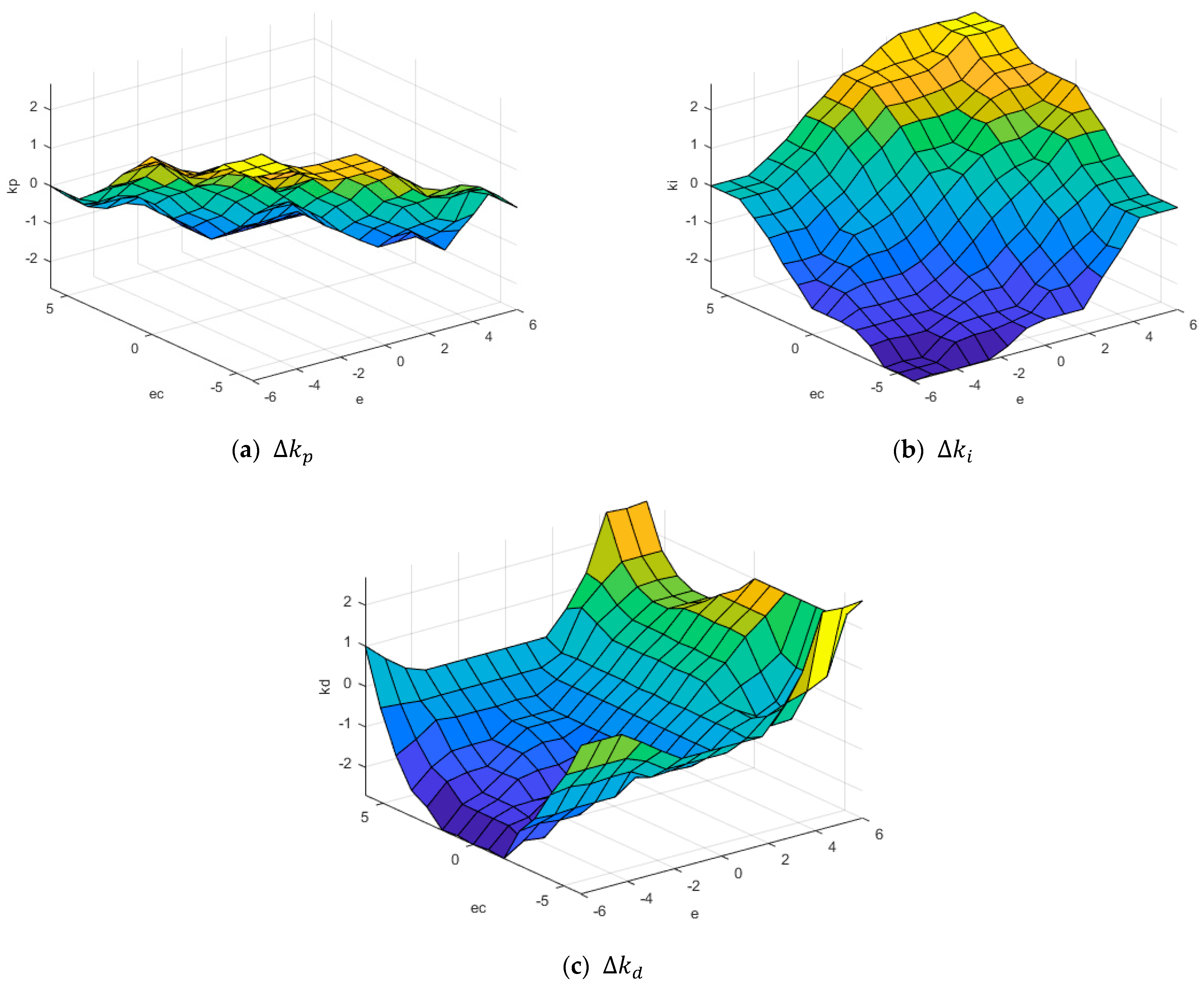
Figure 12 is the characteristic face of the fuzzy inference system.
Through fuzzy logic inference, the output is a fuzzy set, and defuzzification is performed using the centroid method:
where
is the membership function of the fuzzy set
at the element
in the universe of discourse
, and
is the
-th element in the universe of discourse
.
By combining the PID controller and the fuzzy controller, the system continuously monitors the error and the rate of change of the error . Through a specified fuzzy algorithm, appropriate , , and values are determined and then output to the PID controller, thereby controlling the system’s operation.
3.3. PSO-Fuzzy-PID Controller
While fuzzy control can dynamically adjust PID parameters to effectively respond to environmental changes, the initial PID parameters and the quantization and scaling factors of the fuzzy control remain fixed and cannot be modified in real time, suggesting room for further optimization. The Particle Swarm Optimization (PSO) algorithm [
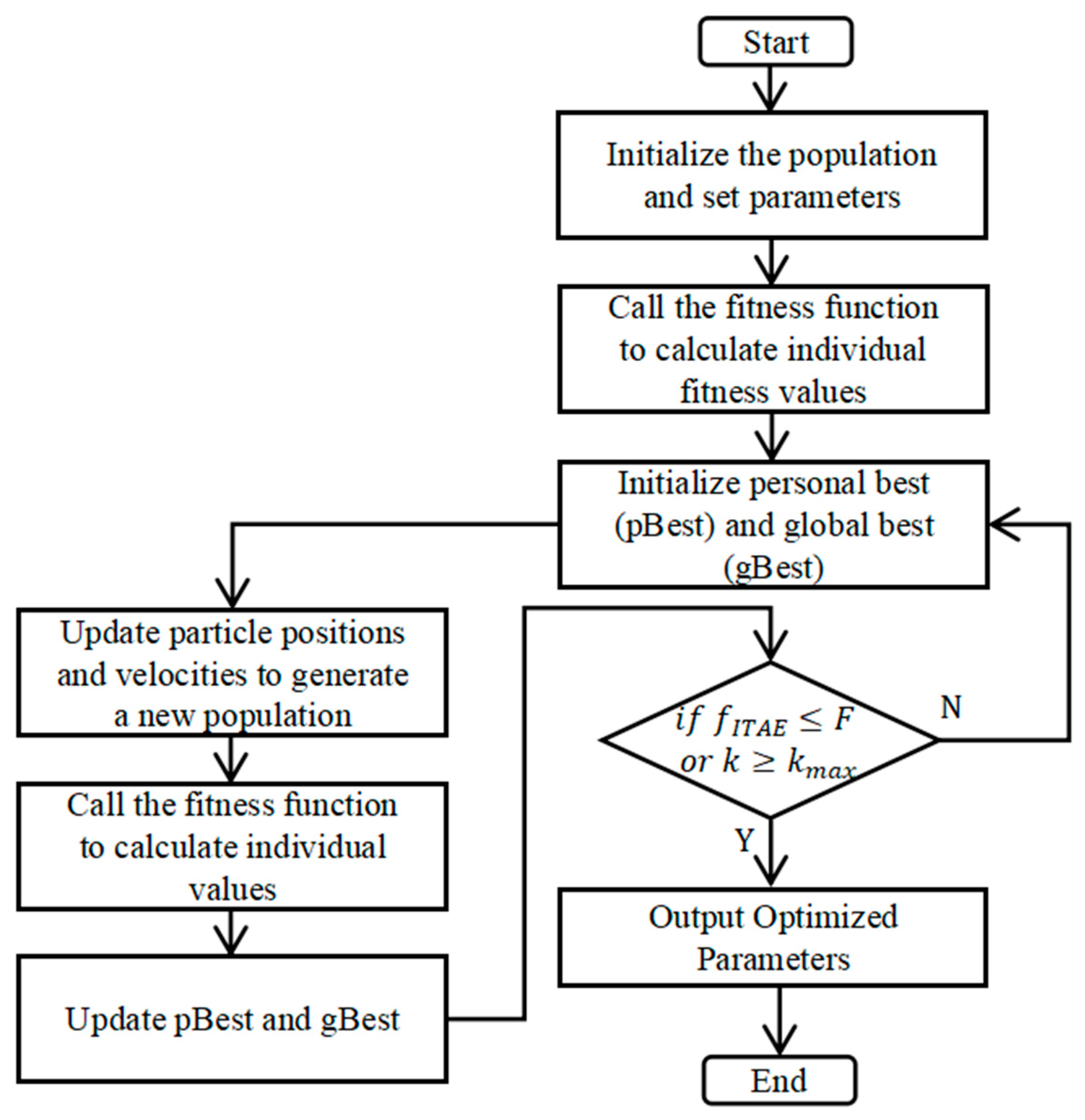
37] is a heuristic optimization technique that mimics the collective behavior of bird flocks or fish schools. It searches for the optimal solution by adjusting the position and velocity of particles, updating based on both individual and group best historical solutions, with the goal of identifying the global optimum. In this study, the PSO optimization is run offline, mainly considering the computational time-consuming and safety issues. Since each simulation takes several minutes to hours, it cannot meet the real-time control requirements, and the offline optimization can avoid the interference of online debugging on the operating state of the diesel engine. The optimized parameters are solidified into the controller after experimental verification, and can be combined with edge computing to realize quasi-online optimization in the future. The steps of the PSO optimization algorithm are shown in
Figure 13.
In a 1-
search space, there are
particles forming a population, with the
particle represented as a
-dimensional vector:
The velocity of the
-th particle is
Each particle also needs to store the best solution it has found so far, denoted as
, as well as the global best solution found by the entire population, denoted as
. The velocity and position of the
-th particle are revised using the following equation:
where
pid is the personal best solution for the i-th particle.
pgd is the global best solution for the entire population.
w is the inertia weight.
c1 and c2 are learning factors.
r1 and r2 are random numbers in the range [0, 1].
Steps for PSO fuzzy PID Control in this study:
Step 1: Initialize the particle swarm:
Swarm size N = 10, reducing computation time while ensuring convergence.
Dimension D = 5.
Inertia weight w = 0.8.
Acceleration constants and c1 = c2 = 0.2, lower learning rate to avoid particle oscillations.
Maximum particle velocity Vmax = 0.01, minimum velocity Vmin = −0.01.
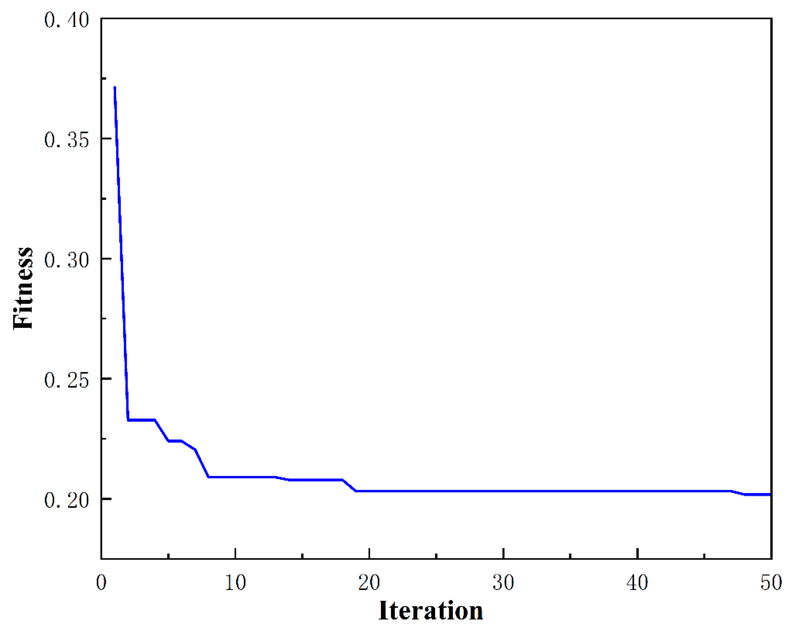
Maximum number of iterations kmax = 50.
Minimum fitness value F = 0.2.
Step 2: Evaluate all particles in the population and calculate their fitness values. Compare each particle’s current fitness with its personal best,
, and assess the fitness of all particles against the global best,
. In this study, the fitness is measured using the ITAE, which represents the integral of the absolute time error. A lower ITAE value indicates better performance [
38]. ITAE serves as a comprehensive metric to assess both the dynamic and static performance of the system. The calculation method is as follows:
where
T is the finite simulation time, which corresponds to the total duration of the simulation. In the initial stage, each particle calculates its fitness value based on its current position and takes it as the initial personal best solution. Meanwhile, the fitness values of all particles in the population are compared with the historical global best solution. If a better fitness value is found, the current global best solution is updated.
Step 3: Update the particle state. Compute the new velocity and new position for the particle to be updated [
39]. Then, calculate the fitness of the new position. If the fitness of the new position is higher, the particle’s position is updated; otherwise, the position is not updated.
Step 4: Check if the termination conditions are met. Determine if the iteration count or other conditions meet the stopping criteria. If satisfied, exit the loop and output the optimal result; otherwise, return to Step 2 and continue iterating.
The PSO-optimized quantization factors and scale factors are shown in
Table 6, and the optimization results of the fitness values are shown in
Figure 14.
4. Results
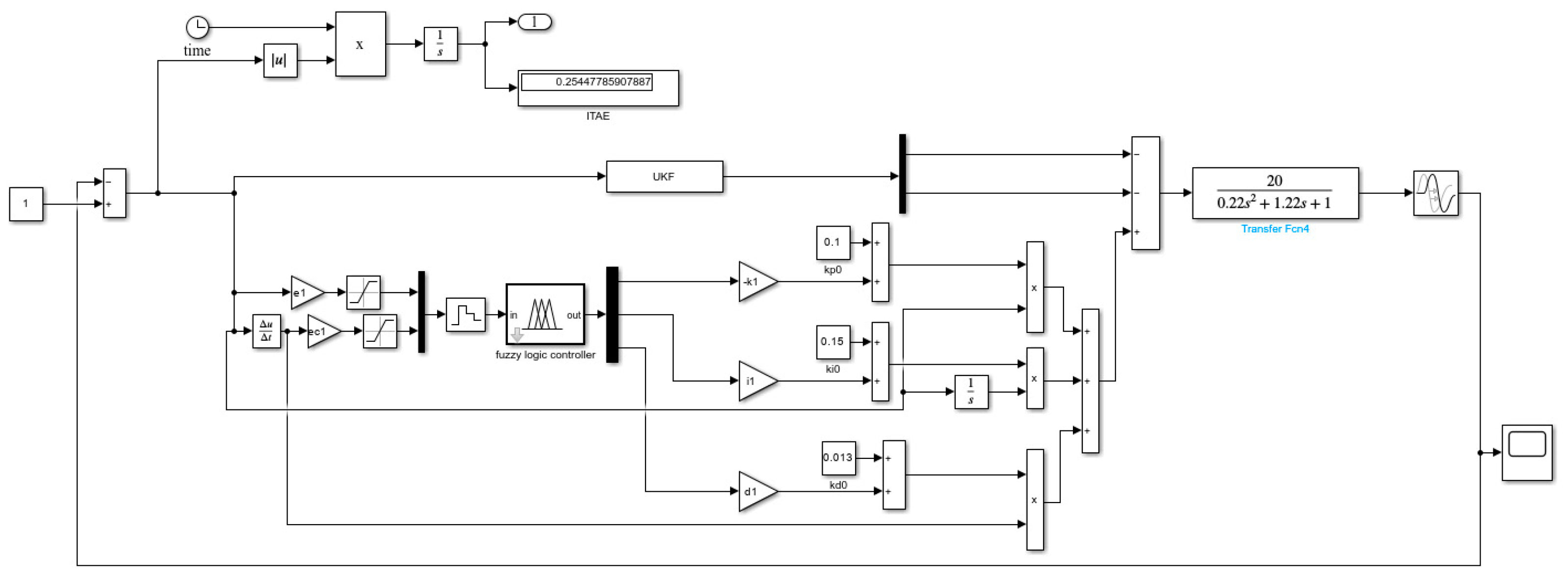
The model of the algorithm discussed in this study is shown in
Figure 15. Four algorithms are modeled using Matlab/Simulink (R2022b): traditional PID control algorithm, fuzzy PID control algorithm, combination of UKF and fuzzy PID control, and fuzzy PID control algorithm based on particle swarm optimization of UKF, as shown in
Figure 16.
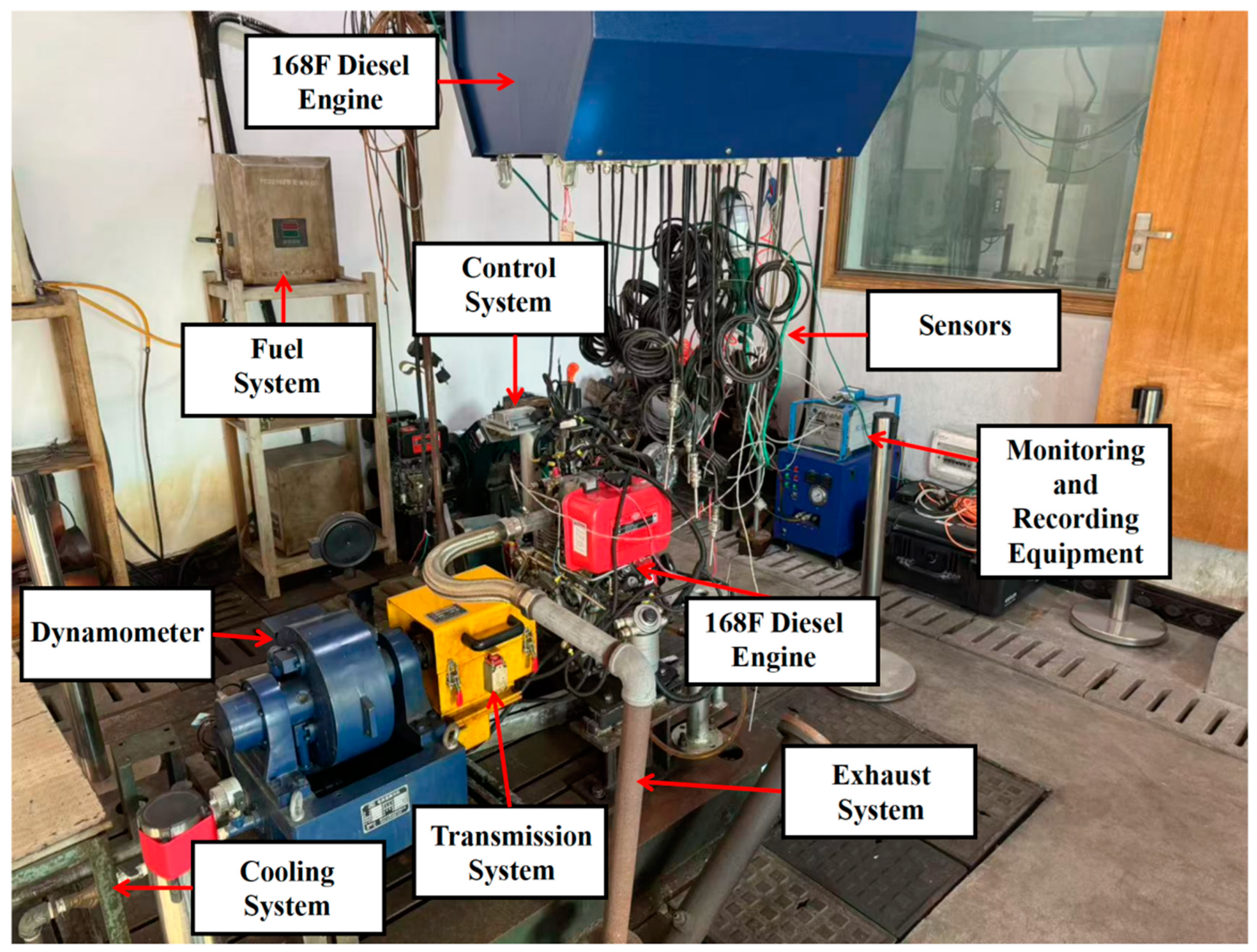
The 168 F single cylinder diesel engine used for simulation and experimentation has a maximum power of and a maximum speed of . The step response experimental condition is that the diesel engine is under a constant load ; the speed was increased to , and the load decreased from to at for sudden load change experiments. The entire simulation process lasted for 100 s, with a sampling interval of s.
To better simulate the interference and measurement noise present in the actual working environment of the diesel engine, the same noise was attached to each of the control algorithms. During the simulation process, the system response characteristics and control effects of each control algorithm were recorded.
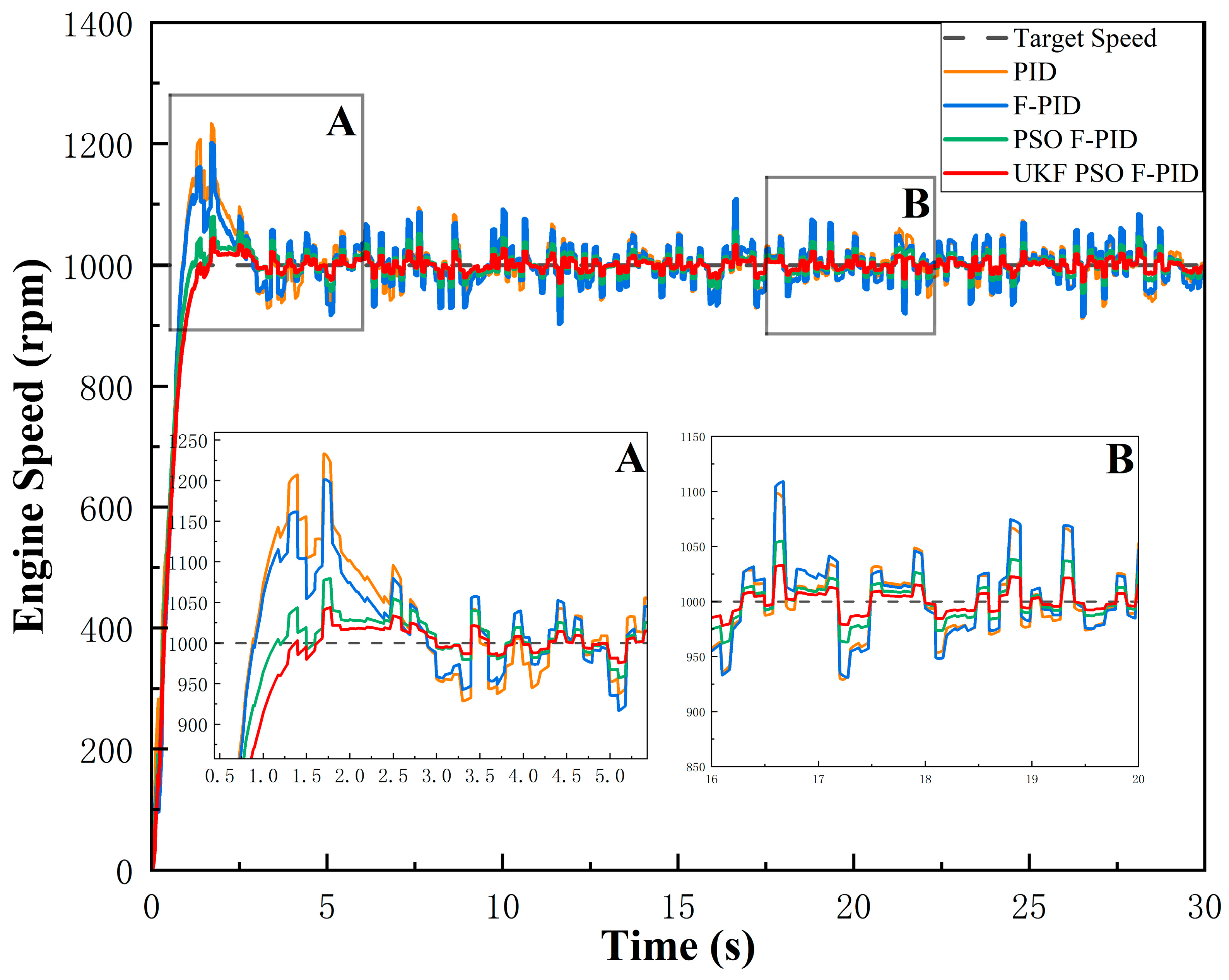
Figure 17 and
Figure 18 present the response curves of the different control algorithms, while
Table 7 and
Table 8 list a comparison of their parameters.
By analyzing the response curves in
Figure 17 and
Figure 18, it is obvious that the UKF PSO-Fuzzy-PID algorithm has significant advantages under the same disturbing noise conditions. The specific advantages are as follows:
Reduced Overshoot: Compared with the traditional PID algorithm, the speed overshoot of the diesel engine using the UKF PSO-Fuzzy-PID algorithm is reduced by 76% under the starting condition, and the overshoot is reduced by 27% under the load disturbance condition. This shows that the system is more stable when reaching the target speed.
Shorter Adjustment Time: The UKF PSO-Fuzzy-PID algorithm reduces the tuning time for the speed step by 1.89 s, and the tuning time for the load disturbance condition by 0.1 s. The diesel engine speed reaches the target speed faster under the step condition, but the responsiveness performance is less improved for the load disturbance condition.
Smaller steady-state error: Under steady-state conditions, the steady-state error of UKF PSO-Fuzzy-PID algorithm is smaller; compared with PID, the steady-state error is reduced by 87% and 55%, respectively, which indicates that the diesel engine can accurately maintain the target speed under the influence of noise, and the algorithm performs well in filtering the noise.
Stronger noise reduction capability: The use of UKF improves the noise reduction ability of the system and reduces the influence of interference noise on the control accuracy; the experimental results verify that the UKF PSO-Fuzzy-PID algorithm improves the noise reduction effect under the high-noise environment by 25% and 31%, respectively.
5. Conclusions
Aiming at the single-cylinder diesel engine speed control, an improved fuzzy PID controller is designed based on the mathematical model of the diesel engine, analyzing the fuzzy control theory and using empirical data to design the type, number, and membership functions of the input and output fuzzy subsets.
The Unscented Kalman Filter is used to improve the robustness of the system against noise and disturbances. The UKF has the predictive ability to filter noise and disturbances, which improves the estimation accuracy of the system state, and thus can improve the accuracy of the feedback data of the speed control system of the diesel engine. The estimation of the system state by the UKF can tell the actual speed of the diesel engine more accurately, so that the fuzzy controller can obtain more accurate input data.
Finally, the PSO fuzzy PID diesel engine speed controller is designed according to the data screened by the UKF. The globally optimized PI parameters of the PSO-optimized fuzzy PID algorithm improve the adaptability of the system to nonlinear and dynamic changes, and the PSO fuzzy PID algorithm possessed the capability to adapt itself to the complex conditions of the diesel engine speed control by online adjusting of the PID control parameters, so that the system control accuracy and accuracy can be improved. Through the online adjustment of PID control parameters, the PSO fuzzy PID algorithm has the ability to adapt itself to the complex working conditions of diesel engine speed control, so that the control accuracy and robustness of the system are improved.
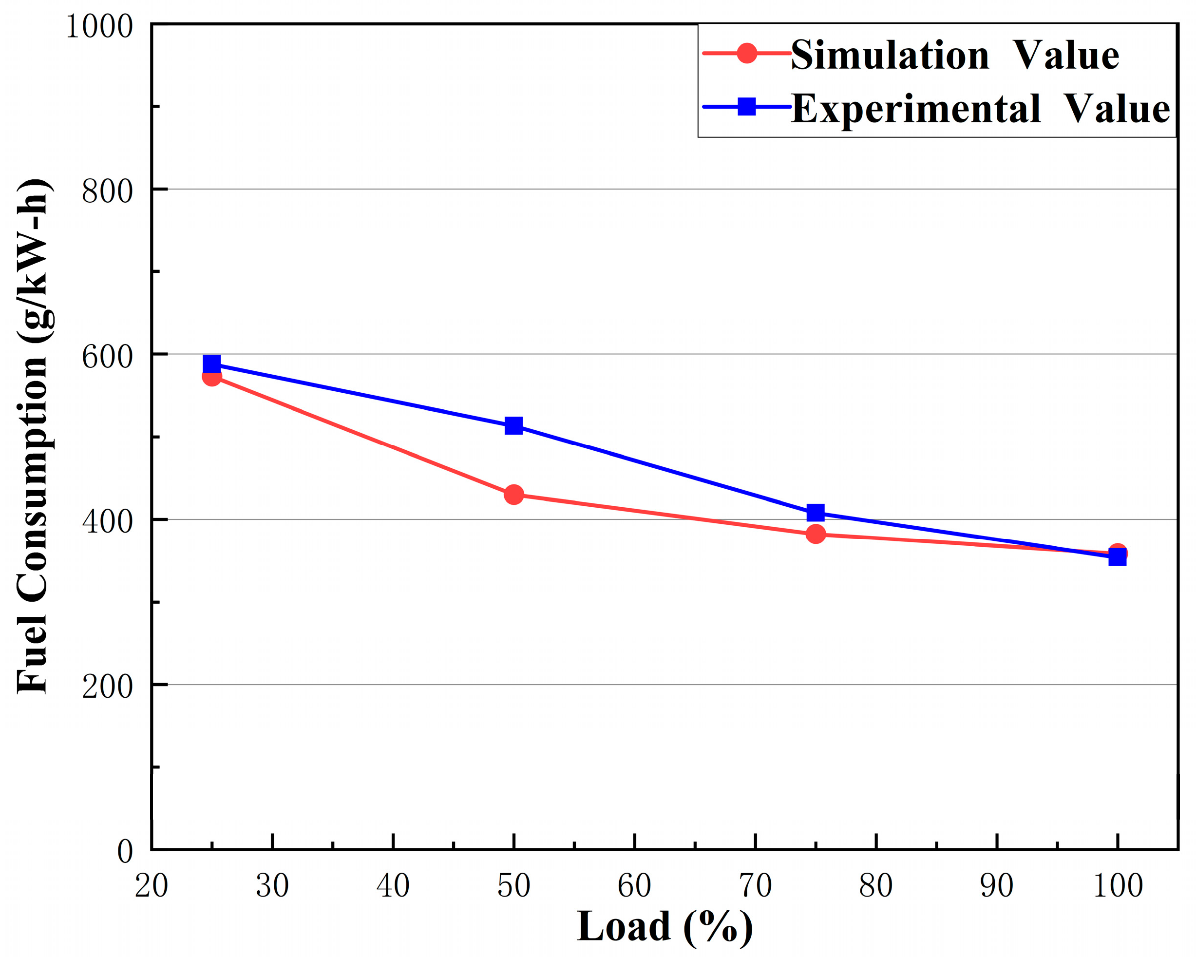
The cylinder pressure and fuel consumption parameters in the mathematical model of the modeled diesel engine are compared through simulation of, and experiment on, various diesel engine conditions. Finally, a joint simulation was conducted to compare the improved controller with the conventional PID controller, and the results show that the control accuracy and stability of the PSO fuzzy PID control over the UKF data are significantly better than those of the conventional PID controller.
The computational model of this study has several potential limitations and uncertainties, as follows:
The error due to model simplification is mainly reflected in the limitation of the first-order inertia assumption, Equation (5), which simplifies the complex diesel engine system to , but this assumption may fail under transient operating conditions (e.g., sudden unloading), especially when high-frequency characteristics such as turbocharger dynamics, intake and exhaust fluctuations, and so forth are not taken into account.
The shortcomings of the linear actuator model are also of concern. The electromagnetic actuator transfer function in Equation (11) ignores nonlinear factors such as magnetic saturation and hysteresis loops, which may lead to phase lag under high-frequency control signals. Regarding parameter uncertainty, the time-varying nature of the friction torque is caused by mechanical wear during long-term operation, resulting in a change in the friction coefficient, while the model assumes that is a constant value, whose potential impact on the stability of the control needs to be further discussed.
The idealized assumptions of the sensor noise model is assumed to be Gaussian white noise, and do not take into account the periodic disturbances of the actual Hall sensors (e.g., harmonic noise due to the eccentricity of the gear disk mounting).
The current work only verifies the static matching between GT-POWER and Matlab/Simulink (R2022b), but does not realize the dynamic co-simulation with the GT-POWER model, which may underestimate the coupling effect under transient conditions.
The goal of future research is to implement the controller in the hardware of a real diesel engine system to further verify its effectiveness and reliability in industrial applications.


