Article

Experimental and Numerical Study on the Combustion and Emission Characteristics of Diesel and Ammonia in Dual Direct Injection Mode in an RCEM

1
College of Control Science and Engineering, Bohai University, Jinzhou 121013, China
2
School of Energy and Power Engineering, Dalian University of Technology, Dalian 116024, China
*
Author to whom correspondence should be addressed.
Processes 2025, 13(3), 751; https://doi.org/10.3390/pr13030751
Submission received: 23 December 2024 / Revised: 10 February 2025 / Accepted: 20 February 2025 / Published: 5 March 2025

Abstract

:
Nowadays, the use of ammonia as a green fuel for internal combustion engines has attracted wide attention. The diesel/ammonia dual direct injection mode has shown great potential, but there is still a lack of basic research on injection strategies for this mode. In this study, the combustion and emission characteristics of diesel/ammonia dual direct injection mode were investigated using a rapid compression and expansion machine (RCEM) combined with CONVERGE software_v3.0. The research focuses on the effects of two injection strategies, including ammonia injection pressure, the ammonia injector nozzle hole diameter, and the compression ratio. The results indicate that minor increases in ammonia injection pressure have negligible impacts on emissions with the same nozzle hole diameter. Increasing the nozzle hole diameter significantly reduces unburned ammonia emissions while increasing HC and N2O emissions. Increasing the compression ratio enhances diesel combustion but does not significantly affect ammonia combustion. Considering the ammonia energy substitution rate and the combustion performance of the actual engine, a high ammonia injection pressure and compression ratio are necessary for engine applications, while an appropriate ammonia orifice diameter is required to meet the emission performance.

1. Introduction

Ammonia (NH3) emerges as a promising alternative fuel for ICEs, offering several advantages. Ammonia combustion does not produce CO2, thus positioning it as a potential zero-carbon fuel. Unlike hydrogen, another potential zero-carbon fuel, which poses storage and transportation challenges due to its low density and high flammability [1], ammonia is easier and safer to handle, and can be stored as a liquid at relatively low pressures [2]. Additionally, ammonia is extensively manufactured and utilized in the chemical and agricultural industries, supported by a well-established distribution system [3]. Despite its high auto-ignition temperature and slow flame propagation speed, which present challenges for use in conventional engines [4], current research endeavors aim to overcome these obstacles. By employing advanced combustion technologies and optimizing engine design, ammonia has the potential to offer a practical solution for reducing greenhouse gas (GHG) emissions and advancing towards a sustainable energy future.
Current research on ammonia fuel combustion strategies primarily aims to address several issues arising from its high ignition temperature, narrow flammability range, and slow flame propagation speed [5]. Notably, ammonia has a high octane number and good anti-knock performance, making it suitable for high compression ratios. Therefore, compression ignition engines may be more suitable for the widespread application of ammonia [6]. However, Grey et al. [7] highlighted the difficulty of using ammonia as the sole fuel in compression ignition engines, necessitating alternative methods to enhance its ignition stability and combustion performance. To improve the combustion characteristics of ammonia, it is essential to use active fuels to facilitate the combustion process. In addition, it is important to note that ammonia contains a nitrogen element, which may lead to an increase in NOx emissions, and its narrow flammability range may also lead to an increase in unburned ammonia emissions. Therefore, it is necessary to control the emissions of various pollutants on the basis of improving combustion performance.
Using active fuels such as diesel and dimethyl has shown promise in igniting ammonia effectively, thereby enhancing its combustion performance [8,9]. Currently, the combustion strategies are primarily divided into the diffusion combustion mode and premixed combustion mode. In the ammonia premixed combustion mode, the low flame propagation speed results in a prolonged combustion duration. Researchers have found that blending highly reactive fuels such as methane [10,11], ethanol [12,13], and hydrogen [14,15] improves flame propagation speed, and some engine studies have also demonstrated that blending methane and hydrogen improves combustion performance [16,17]. However, premixed fuel can influence diesel ignition [18,19], leading to high emissions of unburned ammonia and NOx, which need to be controlled [20,21]. Additionally, the supply of pilot fuel, ammonia, and highly reactive fuel complicates the engine structure and increases costs. Although there are strategies like diesel fuel split injection, which improves mixture reactivity by pre-injecting diesel fuel [22,23], further in-depth research is still needed. In the diffusion combustion mode, the combustion rate is determined by the mixing rate of fuel and air, compensating for ammonia’s slow flame speed. Considering the high reactivity of diesel and its well-established theoretical framework, some researchers have studied the combustion and emission performance of diesel/ammonia in high-pressure dual fuel (HPDF) mode. Wang et al. [24] found that the direct in-cylinder injection of ammonia increased power output, increased economic efficiency by 7.52%, and significantly reduced CO2 and NOx emissions compared to pre-mixed ammonia injection. Zhou et al. [25] optimized a dual-fuel engine model, showing that high-pressure direct injection could achieve higher thermal efficiency and reduce NOx emissions by 47%. Liu et al. [26] developed a stratified injection technique, increasing the ammonia energy ratio to 99% and reducing CO2 emissions, though further experimental validation is required. Valentin Scharl et al. [27] demonstrated that injecting diesel before ammonia prevents ignition failure and enhances spray interaction, leading to higher ammonia combustion efficiency. Zhang et al. [28,29] showed that optimizing the injection timings of diesel and ammonia could reduce N2O emissions in a two-stroke single-cylinder engine, highlighting the importance of spray interactions for stable ignition and efficient combustion. Nadimi et al. [30] observed that with an 84.2% ammonia substitution rate, CO2, CO, and PM emissions decreased, but NOx and unburned ammonia emissions increased significantly. Xu et al. [31], using a Wartsila engine, identified that N2O formation resulted from the slow flame propagation of premixed ammonia and quenching near the wall, while NO originated from ammonia oxidation and high-temperature diesel flames. Zheng et al. [32] discovered that NOx emissions varied with ammonia energy fraction and engine load, increasing at higher loads. They also found that higher intake pressures increased N2O emissions.
In summary, the diesel/ammonia dual direct injection mode has demonstrated the feasibility and potential benefits of compression ignition engines. At present, however, basic research on ammonia/diesel dual direct injection mode is still extremely limited. It is necessary to study the effects of various variables on flame propagation, combustion performance, and emission performance through basic visual experiments to guide the development of practical engines. Currently, the main visualization experimental equipment includes optical engines and constant-volume combustion chambers; however, the former is limited by the cylinder head arrangement, which makes it difficult to arrange two injectors, and regarding the latter, in order to clearly study the single-beam spray and flame propagation characteristics, the fuel injection mass tends to be small, which makes it difficult to accurately collect the real-time cylinder pressure, thus limiting quantitative analysis.
Based on the issues, in this study, a four-stroke rapid compression and expansion machine platform with a visualization cylinder head was used to investigate the combustion characteristics of ammonia/diesel dual fuel through the natural luminescence method. Due to the lack of emission detection equipment support on the RCEM platform, the CONVERGE software_v3.0 was used to model the RCEM platform. After calibrating the model with experimental results, numerical simulations of the emission characteristics were performed. Furthermore, increasing compression ratio, intake temperature, and intake pressure can typically promote engine combustion performance [33,34,35], so comprehensive studies on the effects of injection and ambient parameters for ammonia/diesel in HPDF mode will be conducted, with a critical focus on identifying the optimal conditions. The conclusions of this paper will be important in helping researchers to understand the coupled effects of individual variables on combustion and emission performance in the HPDF model, providing potential strategies to optimize the combustion and emission performance of real engines at a relatively fundamental level.

2. Experimental Setup and Model Establishment

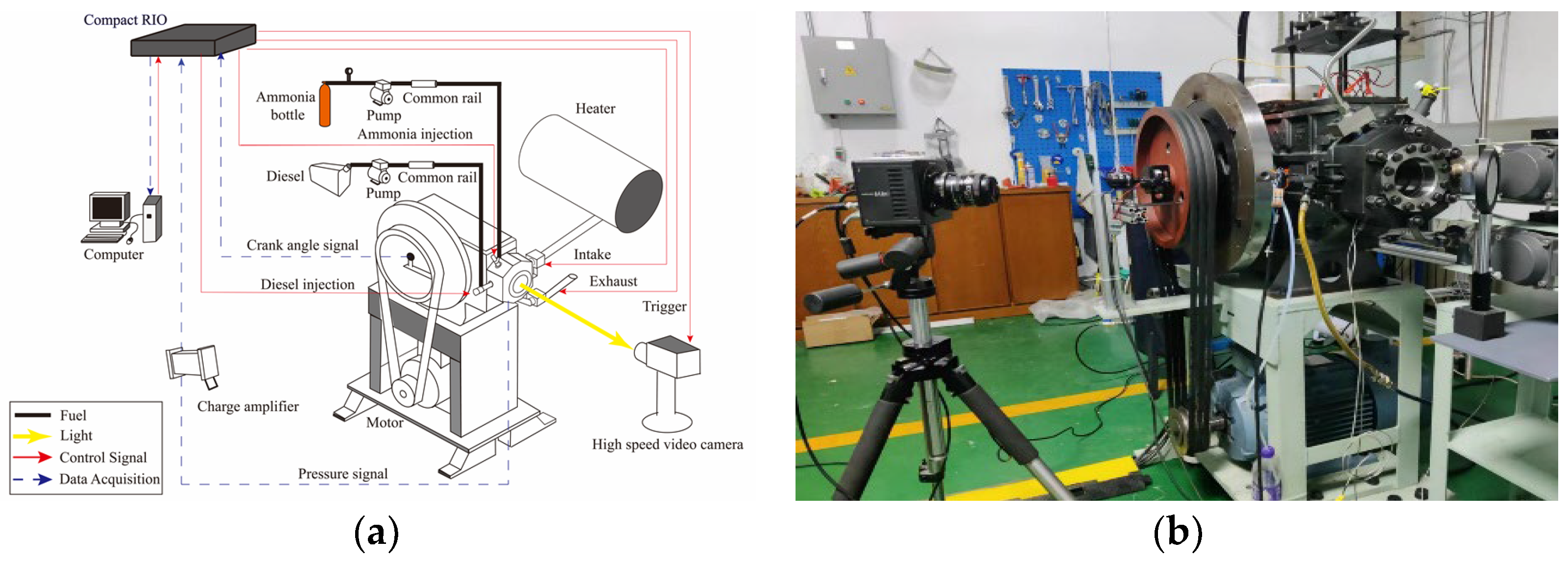
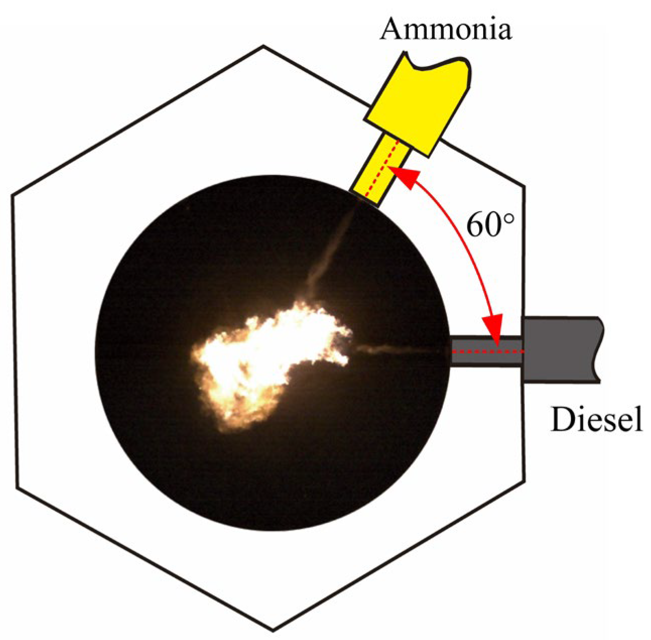
2.1. Experimental Setup

The experimental apparatus consists of an RCEM, a fuel injection unit, a high-speed camera unit, and a signal acquisition and control unit. The schematic diagram of the experimental setup is shown in Figure 1a and a physical drawing of the experimental setup is shown in Figure 1b.
The RCEM was modified from a single-cylinder four-stroke diesel engine with a bore diameter of 135 mm. The RCEM uses a motorized rear trailing drive mode, replaces the original engine cylinder head with a visual combustion test port, and employs a multiple-cycle, single-ignition test method.
The redesigned cylinder head features an observation window constructed from sapphire glass. The window has a diameter of 90 mm and is capable of withstanding a maximum pressure of 20 MPa. The RCEM’s compression ratio has been reduced from 17.5 to 7.66 after modification. In order to maintain the stability of diesel compression ignition, the intake air is heated and pressurized, ensuring adequate compression pressure and temperature in the RCEM. Prior to entering the cylinder, the air undergoes compression to a pressure of 0.38 MPa and is subsequently heated to 500 K using a pipeline heater. The original inlet and outlet valves are substituted by electro-pneumatic ball valves to regulate the intake and exhaust procedures. A K-type thermocouple is installed to measure the steady temperature inside the cylinder before compression. The transient pressure is recorded using a piezoelectric pressure sensor at a 0.2 °CA intervals. The RCEM is driven by an electric motor, with the speed set to 270 RPM.
The fuel injection unit used here consisted of two main parts. The first part was the diesel supply line, which included a diesel tank, a high-pressure oil pump, a high-pressure common rail, and a diesel injector. The second part was the ammonia supply line, which included an ammonia bottle, a gas–liquid booster pump, a high-pressure common rail, and an ammonia injector. Figure 2 depicts the arrangement of the two injectors. The horizontally installed injector was the diesel injector, featuring a single straight hole of 0.12 mm in diameter. The side-mounted injector was the liquid ammonia injector, which had a single straight hole with a diameter of either 0.21 mm or 0.32 mm. The angle between the axes of the two injectors was set at 60° to achieve better combustion characteristics [36].
The visualization experiment was conducted using the natural flame luminosity method. To capture clear images of the flames of diesel and ammonia, a high-speed camera was utilized, operating at a frame rate of 10,000 fps with image resolution of 640 × 480 pixels. In addition, the main experimental equipment’s measurement uncertainties are listed in Table 1.

2.2. Experimental Parameters

The experimental conditions are detailed in Table 2. Each condition was tested three times or more to ensure data consistency. It is important to note that the electromotive force generated by the motor’s reverse drag on the piston during its downward movement in the RCEM might have impacted the cylinder pressure measurements. Therefore, the diesel injection timing for all experimental conditions is fixed at −8 °CA after top dead center (ATDC), so that the combustion process is mainly sustained before the top dead center.

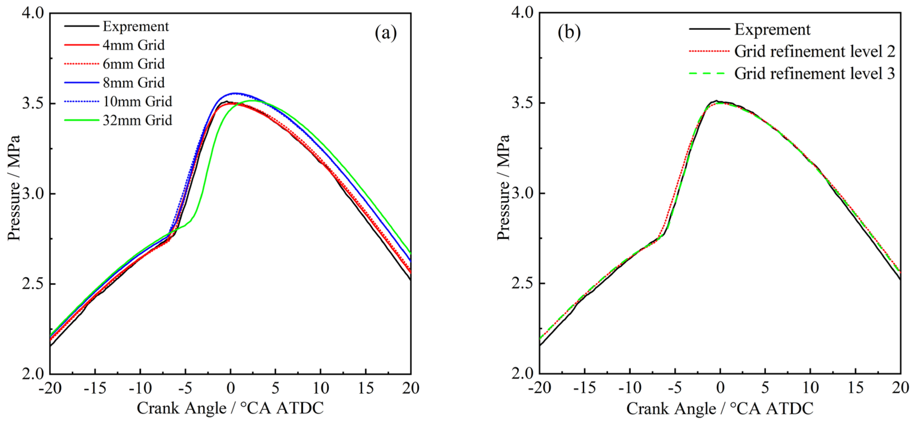
2.3. Numerical Modal
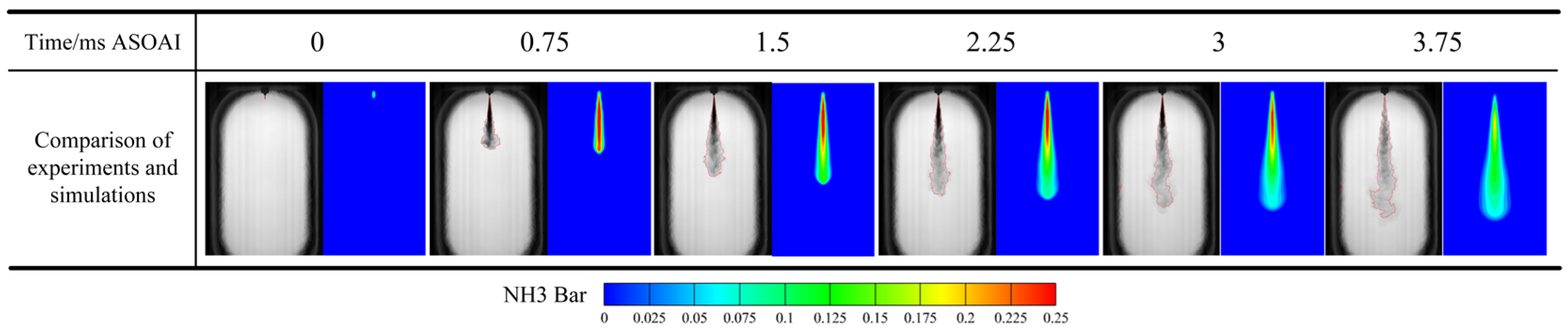
Currently, many potential mechanisms of the HPDF mode remain unexplored. Additionally, the RCEM platform allows only frontal flame images to be observed, which limits the ability to ascertain the spatial distribution and reaction extent of chemical groups during combustion. This limitation hinders the collection of experimental data regarding the formation mechanisms, composition, and proportions of emissions. Consequently, this study utilizes numerical simulations to investigate the emission formation patterns within the RCEM.

2.3.1. Spray Model

Liquid fuel jet is modeled by Lagrangian particles using the KH model, which calculates the process based on the columnar liquid jet instability theory, and the RT model, which calculates the breakup process using the Rayleigh–Taylor instability wave of opportunity; the KH-RT (Kevin Helmholtz–Rayleigh Taylor) model [37] is used for jet breakup, and the NTC model [38] is used for droplet collisions. The Frossling Evaporation model predicts the time-dependent changes in droplet radius, r0, during spray evaporation. The RNG k-ε model serves as the turbulence model to simulate the motion of the in-cylinder flow field. Based on experimental data of ammonia spray, the parameters of the KH-RT model and RNG k-ε model have been adjusted, leading to the calibration of the ammonia spray model. The operational conditions for spray simulation in the constant volume chamber (CVC) are detailed in Table 3. The calibration parameters for the KH-RT model pertaining to the liquid ammonia spray are specified in Table 4, while the constants and empirical coefficients for the RNG k-ε model are outlined in Table 5.
Figure 3 displays the variation in liquid phase penetration distance across different grid sizes, revealing that simulations conducted with a 1 mm grid size aligned more closely with the experimental results. Consequently, simulations utilizing a minimum grid size of 1 mm in the spray development region were employed for further combustion model computations. Figure 4 compares spray patterns using a 1 mm grid, confirming that the simulation results closely match the experimental images, thereby validating the reliability of the spray model.

2.3.2. Combustion Model

The SAGE combustion model was employed to characterize the combustion process. The mechanism utilized in the numerical simulations was derived from XU’s research [38], encompassing 69 substances and 389 reaction sets. This comprehensive mechanism is adept at accurately predicting the combustion process across diverse conditions.
In CONVERGE, the visualizations the cylinder head, piston top surface, and intake and exhaust ports were modeled according to the specifications of the RCEM, as depicted in Figure 5. The model underwent calibration using the cylinder pressure and combustion images captured under condition number 1 in Table 1. The simulation timeline spanned from the intake start time at −360 °CA ATDC to the exhaust valve opening time at 180 °CA ATDC.
To verify grid sensitivity, simulations were conducted using base mesh sizes of 32 mm, 10 mm, 8 mm, 6 mm, and 4 mm. The cylinder pressure curves, as a function of crank angle, are illustrated in Figure 6a. It can be observed that as the grid size decreases, the simulation results more closely match the experimental data. When the grid size was reduced to 4 mm, the resulting cylinder pressure curve was made to closely resemble that of the 6 mm grid size simulation. Thus, to balance calculation accuracy and computational cost, a base grid size of 4 mm was selected for further simulations.
Figure 6b presents a comparison of cylinder pressure curves between the simulation and experimental values at two refinement levels. The simulation results for cylinder pressure at both levels are closely aligned and correspond well with the experimental data. Consequently, to conserve computational time, future simulations are conducted at a refinement level of 2. Figure 7 displays the correlation between temperature field changes from the simulation and the natural flame luminosity images, demonstrating that the simulation accurately depicts the combustion process.

3. Results and Discussion

3.1. Effects of Injection Strategy

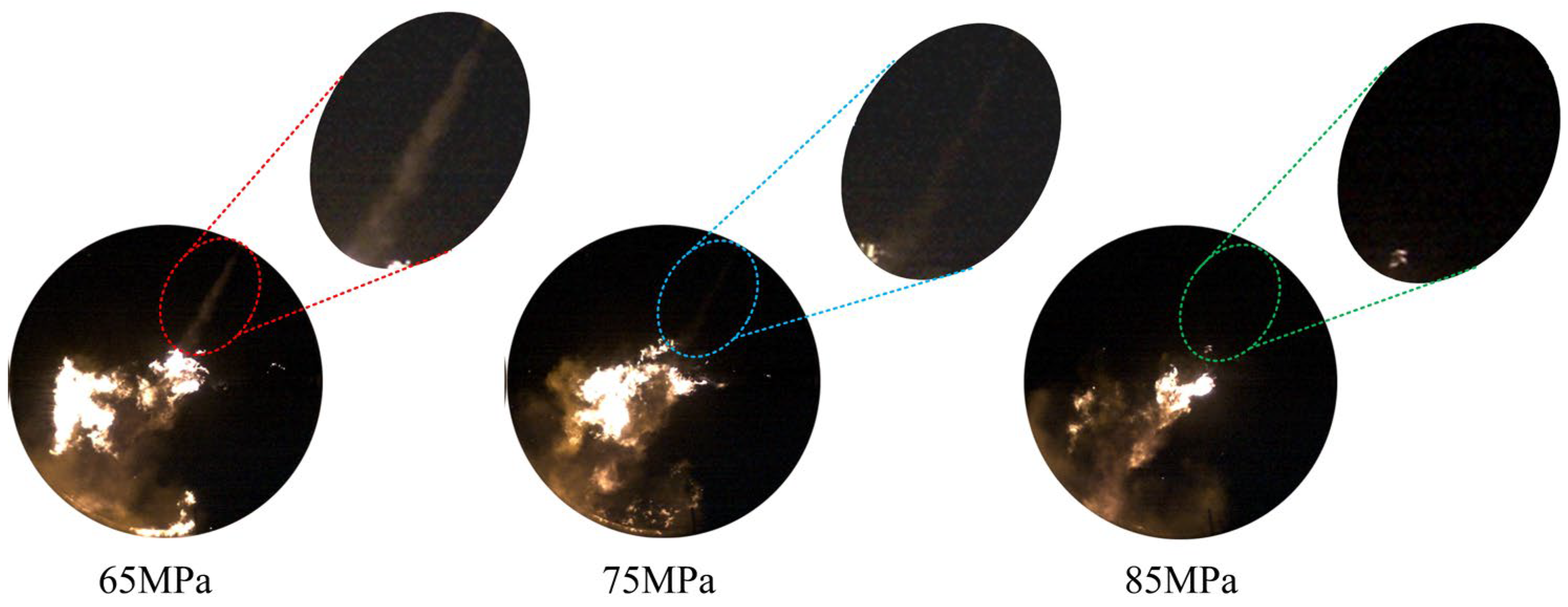
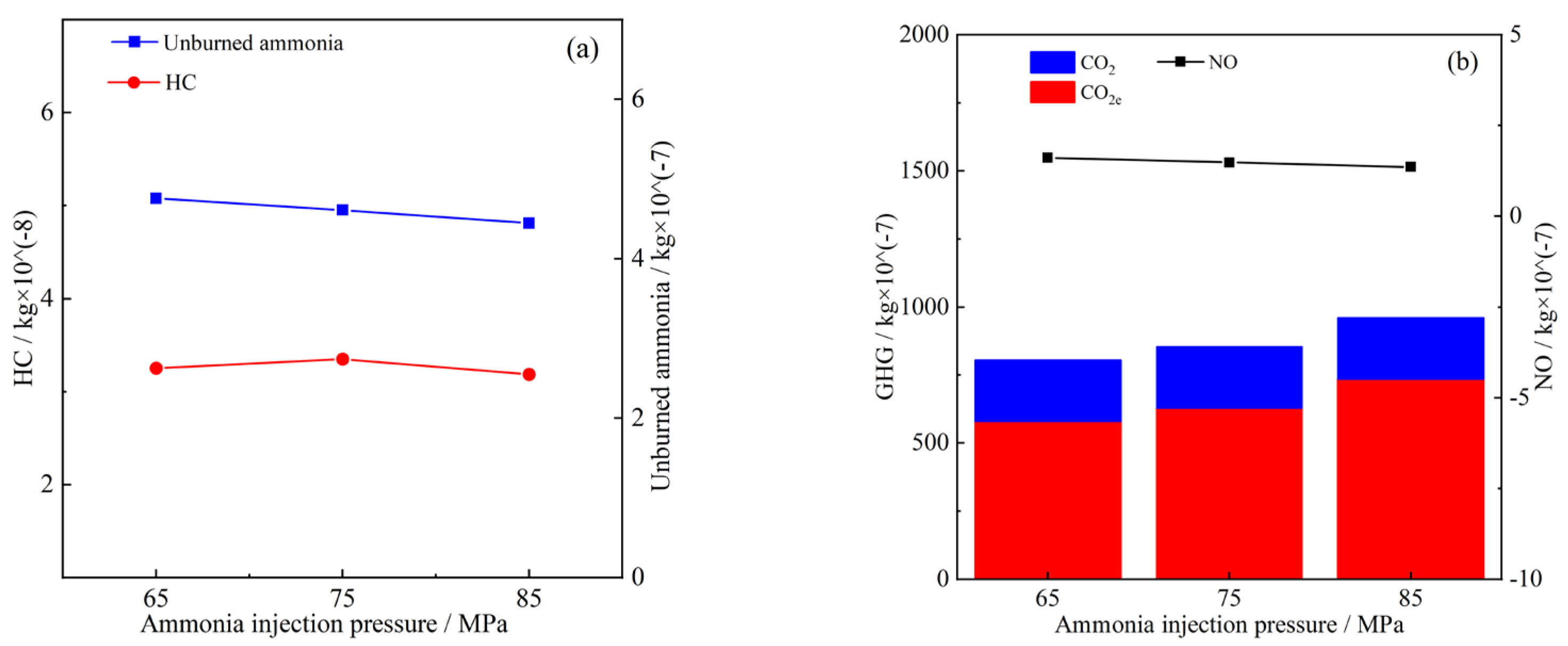
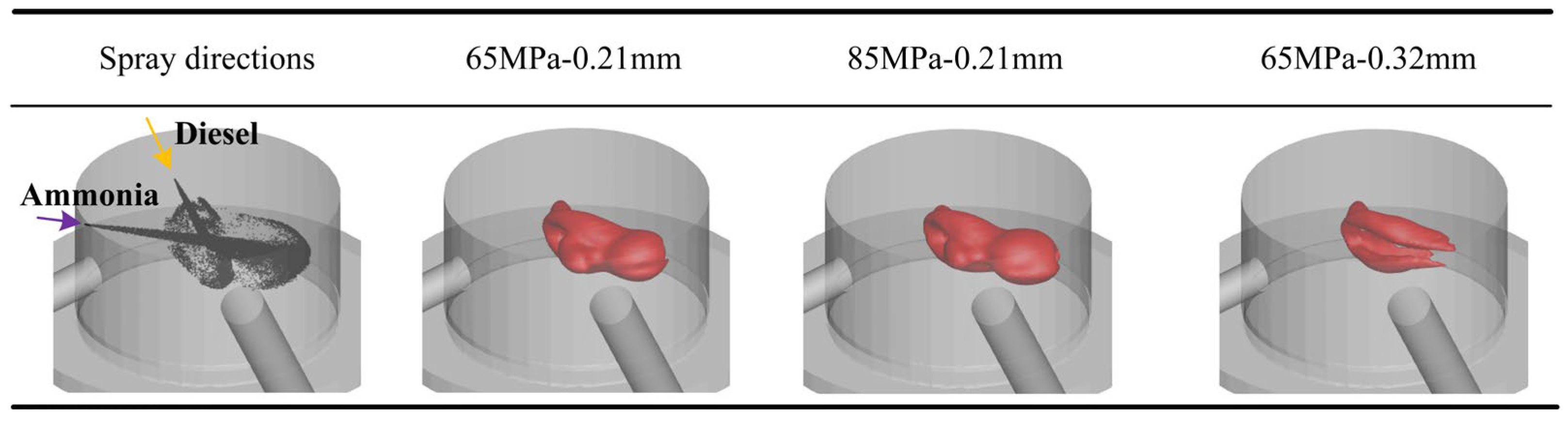
3.1.1. Effects of Ammonia Injection Pressure

In prior research [36], the influence of ammonia injection pressure on combustion characteristics was examined, and the experimental consistency was also verified. The findings suggest that maintaining the same total injection volume while increasing the ammonia injection pressure may lead to an advancement in the ammonia combustion phase and a reduction in unburned ammonia emissions.
Figure 8 displays combustion images at 0.1 °CA ATDC for ammonia at injection pressures of 65 MPa, 75 Mpa, and 85 Mpa. It is evident that combustion reached the late stage under all conditions. However, in the 65 Mpa pressure setting, ammonia was still being injected, resulting in higher unburned ammonia emissions. Moreover, the injection pulse widths at pressures of 65 Mpa, 75 Mpa, and 85 Mpa were 3.77 ms, 3.55 ms, and 3.28 ms, respectively. Relative to the 65 Mpa condition, the pulse width at 75 Mpa was reduced by 14.9%, and that at 85 Mpa was reduced by 8.2%. These reductions in injection pulse width correlate with only slight changes in unburned ammonia emissions.
Figure 9a displays the numerical simulation outcomes for HC and unburned ammonia emissions at three different ammonia injection pressures. The results demonstrate a slight decrease in unburned ammonia emissions with increasing ammonia injection pressure, aligning with earlier findings. Concurrently, HC emissions remain relatively stable, suggesting that under consistent diesel injection pressure and intervals, adjusting ammonia injection pressure alone cannot impact diesel combustion.
Figure 9b displays the numerical simulation results for NO and GHG emissions at three different ammonia injection pressures. The data indicate a slight decrease in NO emissions with increasing ammonia injection pressure, while GHG emissions increased, primarily driven by rising CO2e emissions. CO2e is the equivalent carbon dioxide emission, which is calculated by the formula CO2e = MN2O × 297, where MN2O represents the emission of N2O and the unit of CO2e is Kg. This trend is attributed to the increased amount of ammonia injected per unit time as injection pressure rises, leading to enhanced evaporation and heat absorption by ammonia. This process lowers the combustion temperature and fosters N2O formation. Additionally, this environment suppresses the formation of thermal NO, contributing to the reduction in NO emissions.
In summary, an increase in ammonia injection pressure from 65 MPa to 85 Mpa results in a slight reduction in unburned ammonia and NO emissions, a minor rise in GHG emissions, and no significant change in HC emissions. Given the current experimental setup, elevating the ammonia injection pressure has a negligible effect on the emissions of unburned ammonia, HC, NO, and GHG.

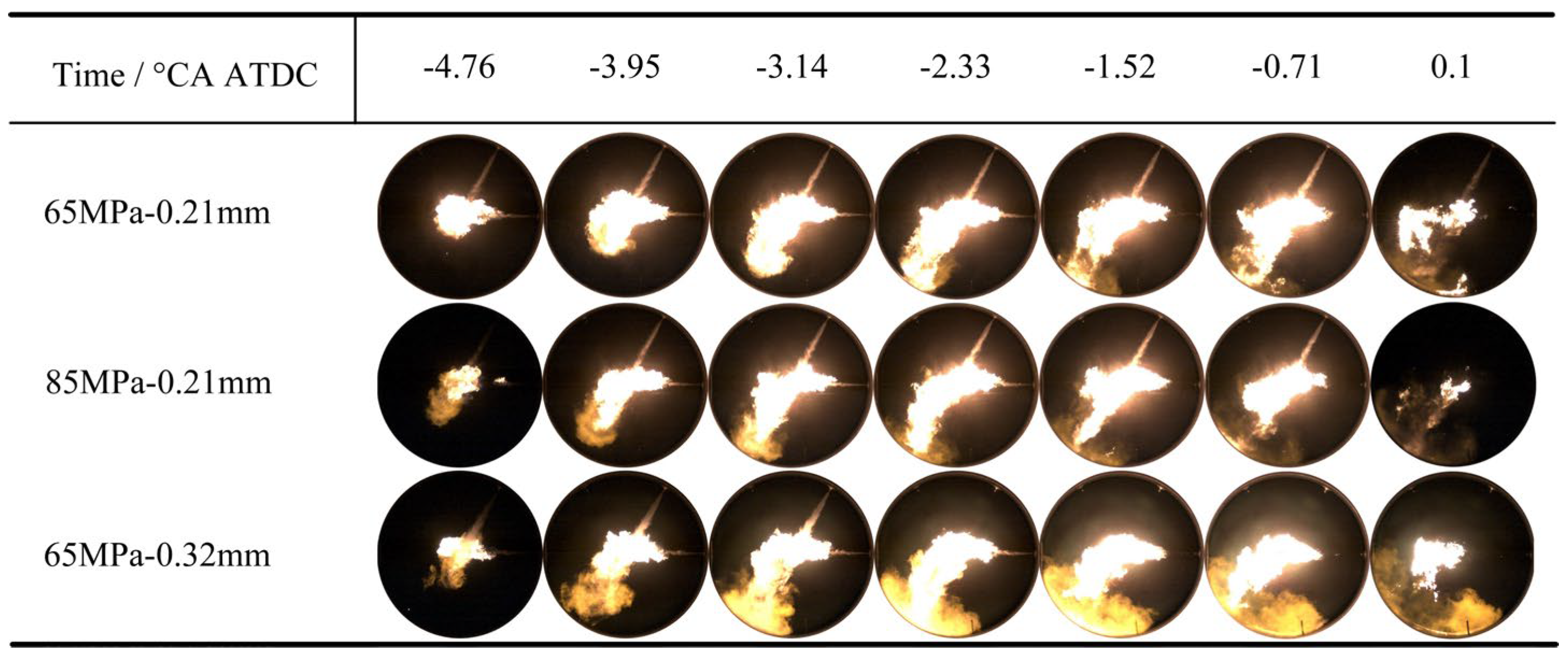
3.1.2. Effects of Ammonia Nozzle Hole Diameter

In previous studies [36], the impacts of varying ammonia nozzle hole diameters on combustion characteristics were explored. It can be observed that increasing the nozzle hole diameter leads to a considerable reduction in ammonia injection pulse width, with a corresponding increase in both peak heat release rate and cylinder pressure. This suggests that a larger nozzle hole diameter for ammonia injection enhances early-stage combustion efficiency, potentially reducing the emissions of unburned ammonia.
Figure 10a presents the numerical simulation outcomes for HC and unburned ammonia emissions under three different settings. It reveals that, in comparison to the 65 Mpa–0.21 mm configuration, unburned ammonia emissions in the 85 Mpa–0.21 mm setup decreased by 6.5%, while the 65 Mpa–0.32 mm setup shows a significant reduction of 35.9%. As shown in Figure 11, for the 65 Mpa–0.32 mm combination, ammonia injection ceased at −2.33 °CA ATDC. In contrast, for the 85 Mpa–0.21 mm combination, ammonia injection ended at −0.71 °CA ATDC, and for the 65 Mpa–0.21 mm combination, ammonia was still being injected at 0.1 °CA ATDC. Diesel injection ceased at −1.52 °CA ATDC, after which the diesel flame gradually diminished and was ultimately extinguished. These observations indicate that, compared to the 65 Mpa–0.21 mm and 85 Mpa–0.21 mm combinations, the 65 Mpa–0.32 mm combination results in more ammonia being injected into the intensely burning diesel flame, leading to a significant reduction in unburned ammonia emissions. Additionally, the above results also demonstrate that enlarging the ammonia nozzle hole diameter is substantially more effective in minimizing unburned ammonia emissions than merely increasing the ammonia injection pressure.
Compared to the 65 MPa–0.21 mm and 85 MPa–0.21 mm settings, HC emissions for the 65 MPa–0.32 mm configuration increased by approximately 53.7%. This increase can be attributed to several factors. In the 65 MPa–0.32 mm setting, the ammonia injection pulse width was notably shorter at 1.9 ms, reduced by 49.6% compared to the 65 MPa–0.21 mm setup. Consequently, the ammonia injection rate into the cylinder per unit time was significantly higher. During the initial combustion phase, an increased volume of low-temperature ammonia spray directly impacted the diesel flame, causing it to quench and leading to substantial HC production. Figure 12 displays the flame at −4.76 °CA ATDC for the 65 MPa–0.32 mm combination, showing the diesel flame bifurcated by the ammonia spray. The red-lined low-temperature area likely resulted from flame quenching, where HC was generated. Figure 13 illustrates the 2000 K temperature iso surface distribution in the cylinder at −4.76 °CA ATDC. It reveals that, compared to the 65 MPa–0.21 mm and 85 MPa–0.21 mm combinations, the 2000 K temperature iso surface remained open in the 65 MPa–0.32 mm setup, with a noticeable gap along the ammonia spray direction. This gap indicates that a significant increase in the ammonia injection rate per unit time drastically lowered the diesel flame temperature, causing incomplete diesel combustion and further HC formation. These findings align with those of Li et al. [39], who concluded that HC generation is primarily due to the quenching of the ignited diesel.
Figure 10b displays the numerical simulation results of NO and GHG emissions under three different combinations. The GHG emissions for the 65 MPa–0.32 mm combination increased significantly, with CO2e emissions increasing by approximately 162.7% compared to the 65 MPa–0.21 mm combination. This substantial rise is due to the gap observed in Figure 13 for the 65 MPa–0.32 mm combination, which created conditions conducive to N2O formation, thereby significantly elevating CO2e emissions. Additionally, NO emissions for the 65 MPa–0.32 mm combination increased significantly by about 107.5% relative to the 65 MPa–0.21 mm and 85 MPa–0.21 mm combinations. In Figure 14, the flame image is contrasted with the numerical simulation results of NO generation for the 65 MPa–0.32 mm setting, showing continuous NO formation throughout the combustion process. Notably, after ammonia injection ceased at −2.33 °CA ATDC, NO generation increased markedly. This increase likely resulted from the cooling effect of the ammonia spray on the diesel flame. Once ammonia injection had ended, the cylinder temperature increased, further boosting the production of thermal NO.

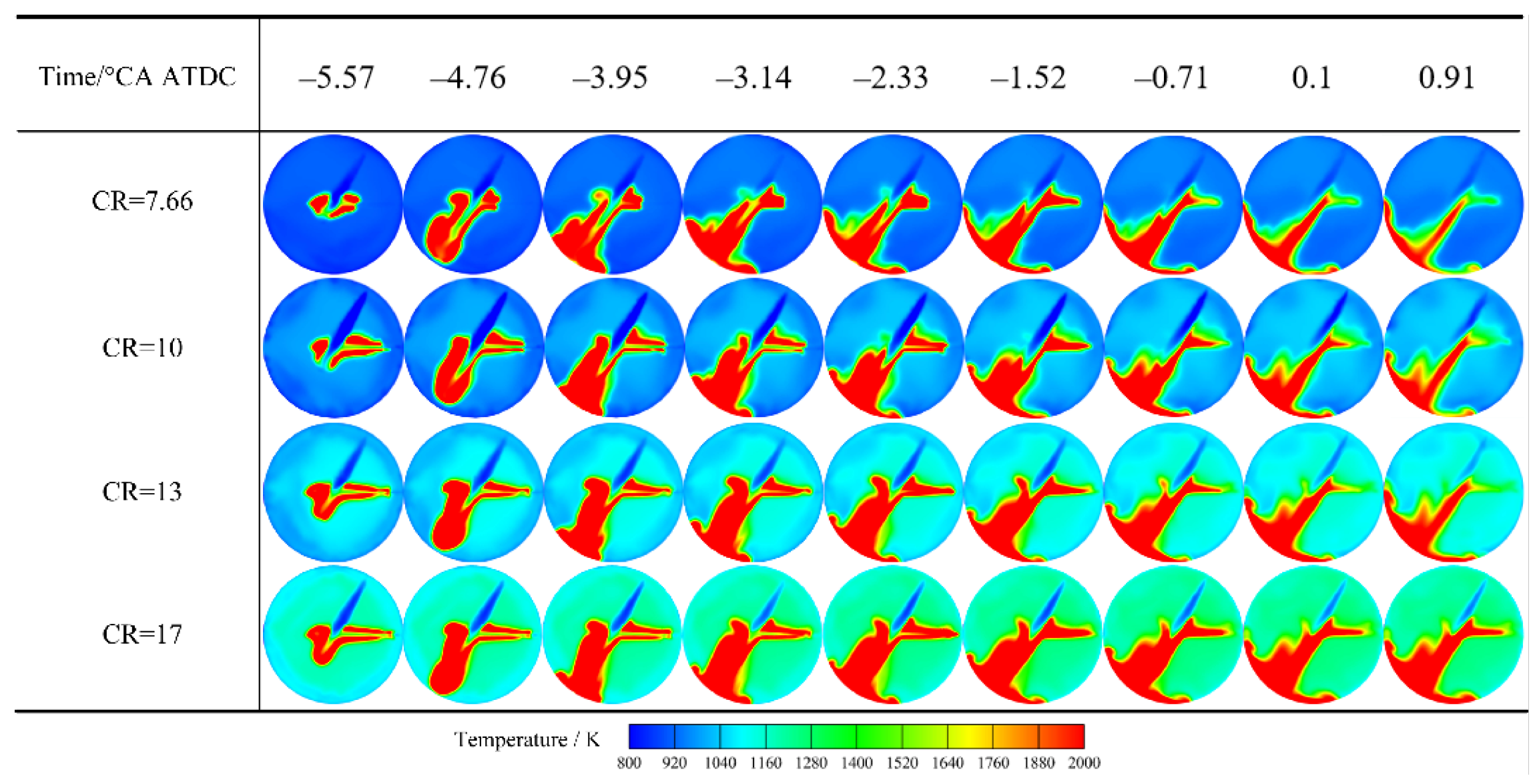
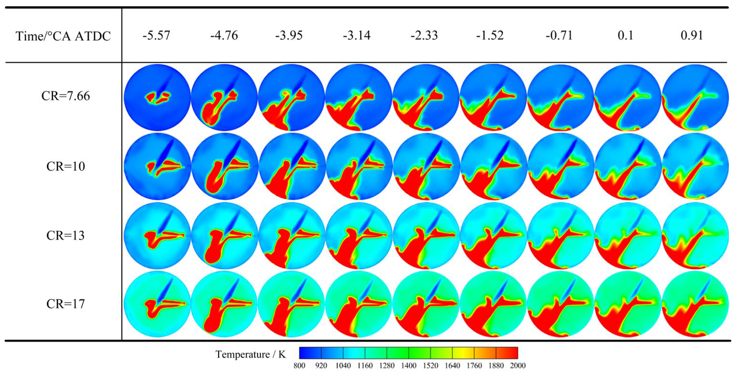
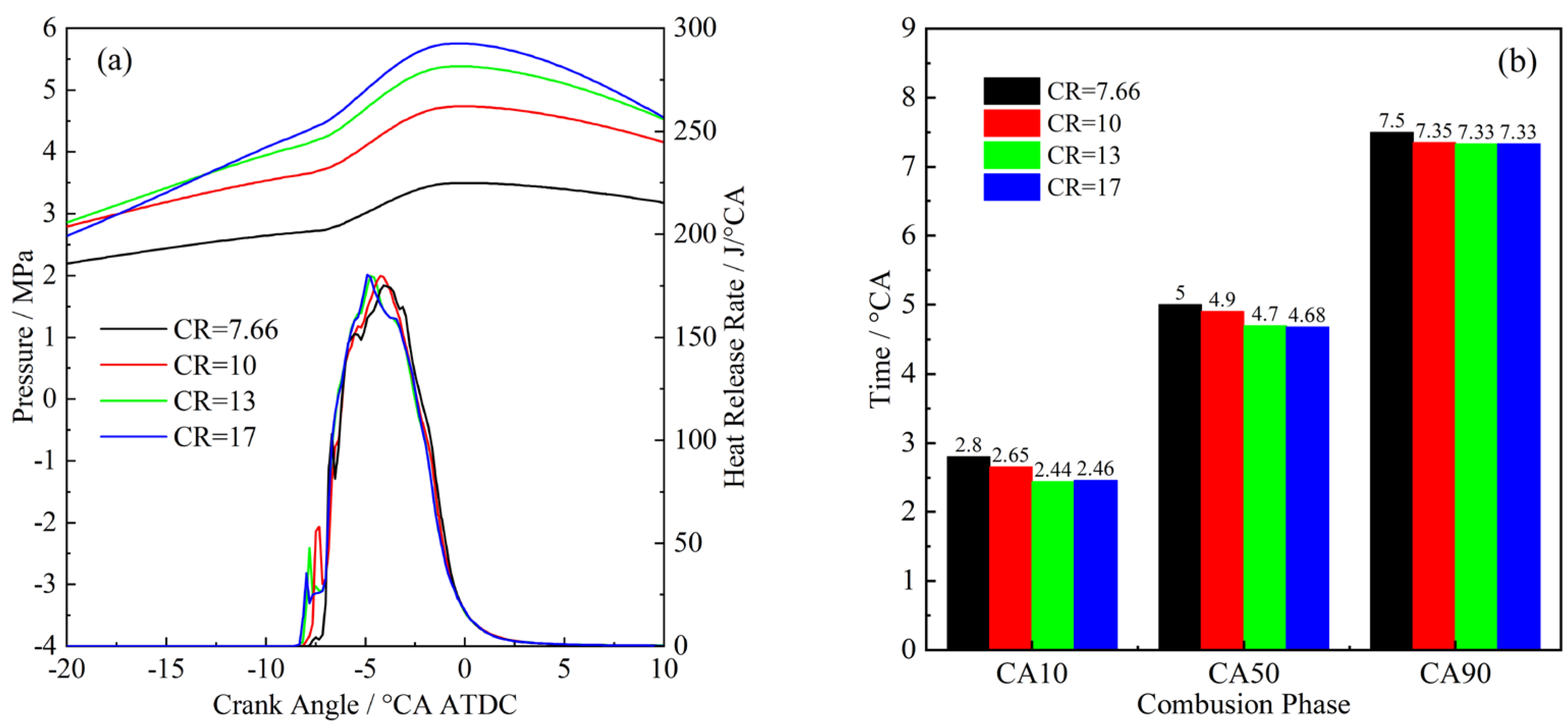
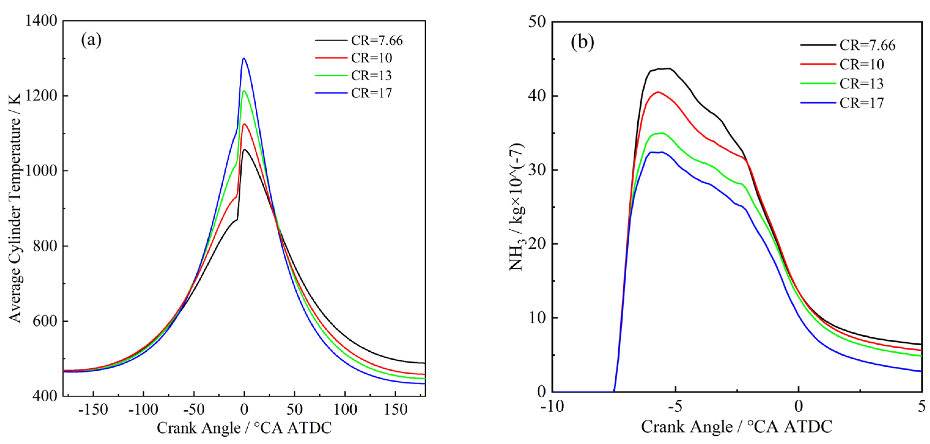
3.2. Effects of Compression Ratio

Coupling Effects of Ammonia Injection Pressure

In this section, the combustion and emission characteristics of HPDF mode under various compression ratios are investigated by numerical simulations. The compression ratio adjustments were here achieved by modifying the top clearance height, with the piston shape and combustion chamber configuration maintained as per the experimental setup. Details of the simulation conditions are provided in Table 6.
Figure 15 shows the temperature variations in the combustion chamber across four different compression ratios. Initially, at −5.57 °CA ATDC, the high-temperature combustion region expanded as the compression ratio increased. However, the growth rate of the flame area started to plateau once the compression ratio surpassed 10. In the mid-combustion stage, between −3.95 °CA ATDC and −2.33 °CA ATDC, while the lift-off length of the diesel flame decreased with higher compression ratios, the overall size of the high-temperature combustion region remained consistent. In the late combustion stage, from −1.52 °CA ATDC to 0.91 °CA ATDC, as the combustion progressed and the cylinder temperature increased, the diesel flame’s lift-off length and the extent of the high-temperature combustion area remained similar across different compression ratios. These findings suggest that increasing the compression ratio raises the average temperature within the cylinder, shortens the ignition delay of diesel, and enhances its combustion efficiency. However, the benefits plateau beyond a certain compression ratio. Additionally, while a higher compression ratio can improve diesel combustion, it has an insignificant impact on ammonia combustion efficiency.
Figure 16a illustrates the variations in cylinder pressure and heat release rate under different compression ratios. As the compression ratio increased, the entire cylinder pressure curve ascended, with peak pressure reaching 4.6 MPa at a compression ratio of 17—a 250% increase over the baseline pressure at a compression ratio of 7.66. Figure 17a details the average cylinder temperatures across various compression ratios, showing a rise in temperature from −50 °CA ATDC to 25 °CA ATDC as the compression ratio increased. At a compression ratio of 17, the peak average temperature hit 1299 K, marking a 23% increase from a compression ratio of 7.66. These observations confirm that higher compression ratios substantially elevate both cylinder pressure and average temperature, enhancing overall combustion performance.
From the heat release rate curves presented in Figure 16a, it is evident that as the compression ratio increased, the peak heat release timing of diesel advanced. This resulted in a shortened ignition delay and earlier diesel ignition timing. Moreover, the peak heat release timing for ammonia also advanced slightly with increased compression ratios, though the peak heat release rates remained almost unchanged. This trend underscores that while raising the compression ratio markedly enhanced diesel combustion characteristics, it had a negligible effect on improving ammonia combustion.
From Figure 16b, it is clear that an increase in the compression ratio reduced the crank angle degrees for CA10, CA50, and CA90 during combustion. However, beyond a compression ratio of 13, further increments showed negligible effects. When comparing compression ratios of 7.66 and 17, we can see differences of 0.34 °CA for CA10, 0.32 °CA for CA50, and 0.17 °CA for CA90. The diminishing differences suggest that while a higher compression ratio advances the combustion phase during the early and mid-stages of combustion, it leads to the convergence of combustion phases in the later stages.
Figure 17b illustrates the variation in ammonia mass fraction within the cylinder from −10 °CA ATDC to 5 °CA ATDC. It shows a significant decrease in ammonia mass fraction between −5.57 °CA ATDC and 2.5 °CA ATDC as the compression ratio increased from 7.66 to 17. This reduction can be attributed to the increased compression ratio shortening the lift-off length of the diesel flame, reducing diesel ignition delay, and enhancing diesel combustion characteristics, which subsequently improved ammonia combustion efficiency.
Figure 18a depicts the effects of varying compression ratios on HC and unburned ammonia emissions. It demonstrates that as the compression ratio increased from 7.66 to 17, there was a substantial decrease in unburned ammonia emissions—approximately 71.3%. This reduction correlates with the patterns shown in Figure 17b, where the shortened diesel ignition delays and the broadened initial ignition zone improved the ignition conditions for liquid ammonia, thereby reducing its emissions. Concurrently, HC emissions also decreased with rising compression ratios. Typically generated from incomplete diesel combustion, HC emissions were mitigated as higher compression ratios elevated the cylinder’s initial temperature and pressure, enhancing the completeness of the diesel combustion process. At a compression ratio of 17, HC emissions were reduced by 92.9% compared to those at a compression ratio of 7.66.
Figure 18b shows how NO and GHG emissions varied with different compression ratios. Notably, as the compression ratio increased, NO emissions rose, while GHG emissions decreased. Figure 19 illustrates the temperature fields and the distributions of NO and N2O across compression ratios of 7.66, 10, 13, and 17. These data reveal that thermal NO predominantly formed in high-temperature flame regions. With higher compression ratios, the expansion of these high-temperature areas led to increased NO emissions. Conversely, N2O predominantly formed in relatively low-temperature regions near the spray front and was absent from high-temperature zones. As the compression ratio increased, the average cylinder temperature rose, which reduced the sizes of regions conducive to N2O formation, and thereby decreased its emissions.
Ammonia–diesel dual-fuel engines offer even greater advantages in terms of reduced pollutant emissions. For single-diesel engines, carbon dioxide emissions from hydrocarbon combustion are well documented, and have a significant impact on the environment, contributing to the greenhouse effect and other consequences. For single ammonia-fueled engines, on the other hand, higher compression ratios and intake temperatures are required, and single ammonia-fueled engines produce large amounts of unburned ammonia due to its poor flammability. Therefore, the ammonia–diesel dual-fuel engine not only reduces carbon emissions, but it also greatly reduces the emission of unburned ammonia, which is a promising future research direction for the application of ammonia to internal combustion engines.
In summary, increasing the compression ratio advances the heat release phase during the early and mid-stages of combustion without significantly changing the peak heat release rate. In the late combustion stage, the heat release phase converges. As the compression ratio increases, emissions of unburned ammonia, HC, and N2O decrease, while NO emissions increase. This suggests that increasing the compression ratio significantly affects emissions but has a smaller impact on combustion characteristics. It enhances diesel combustion but has an insignificant effect on ammonia combustion.

4. Conclusions

In this paper, based on the RCEM and CONVERGE software_v3.0, visualization experiments and numerical simulations were employed to examine how ammonia injection pressure, the ammonia injector nozzle hole diameter, and the compression ratio affect the combustion and emission characteristics of the diesel/ammonia dual direct injection mode. The conclusions are summarized as follows:
  • With the same ammonia injection nozzle hole diameter, minor increases in ammonia injection pressure have an insignificant impact on the emissions of unburned ammonia, HC, NO, and N2O;
  • Under the same ammonia injection pressure, increasing the nozzle hole diameter significantly reduces unburned ammonia emissions. However, it also leads to a noticeable increase in HC and N2O emissions, with no significant impact on NO emissions;
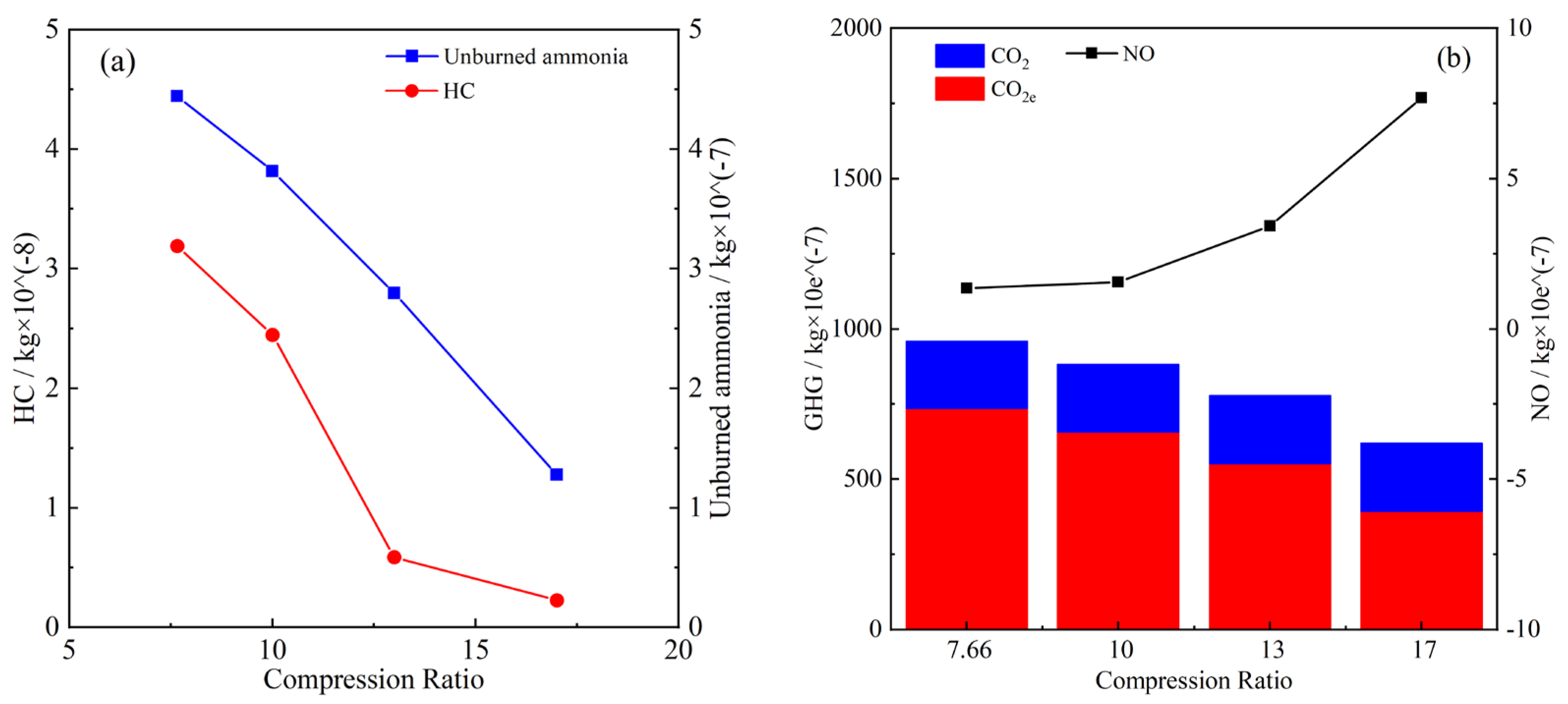
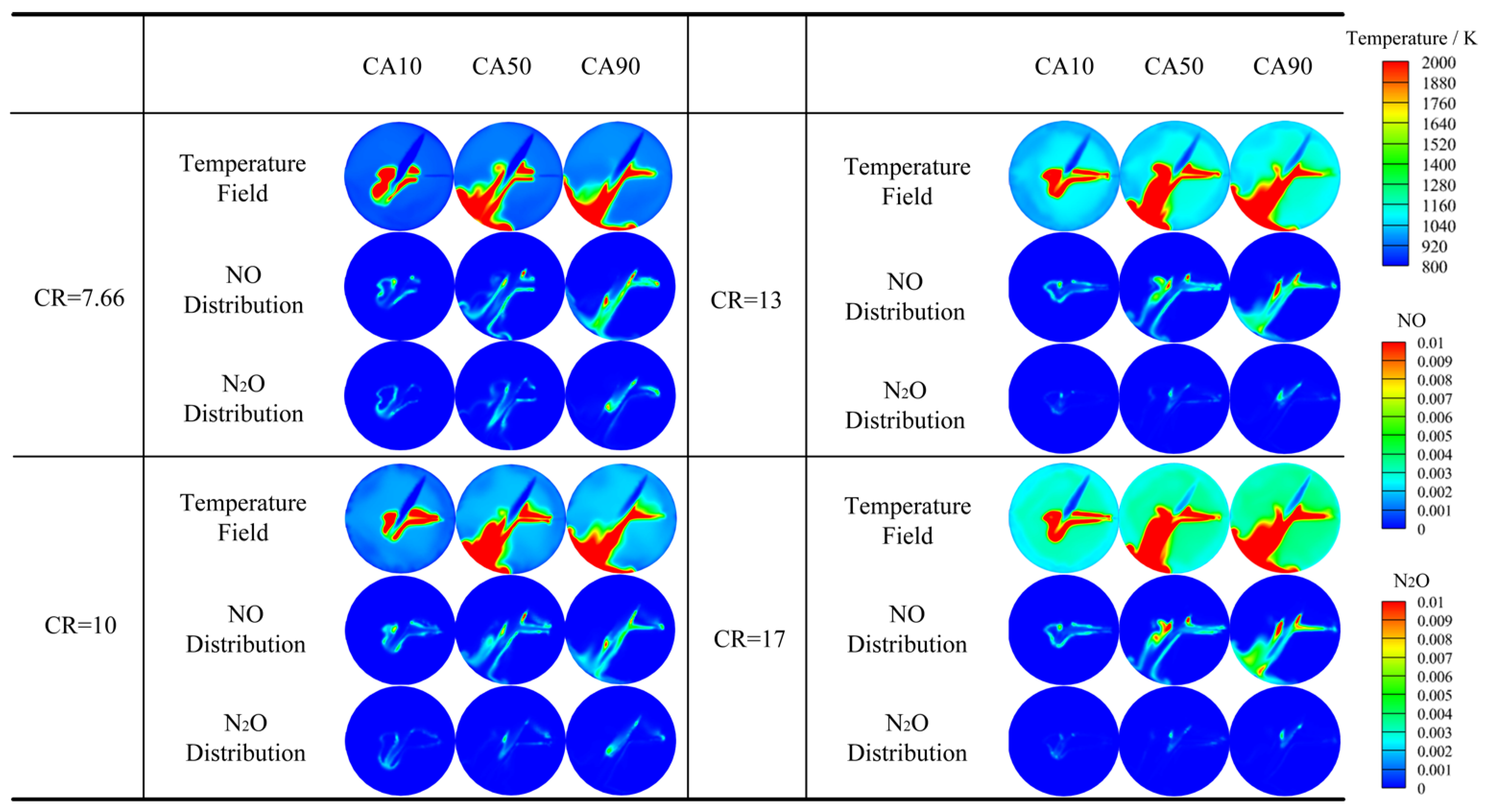
  • Increasing the compression ratio promotes diesel combustion but has no significant impact on ammonia combustion. The benefit of increasing the compression ratio is that it could reduce emissions of unburned ammonia, HC, and N2O, but it would increase NO emissions.
Overall, increasing the liquid ammonia injection pressure can significantly increase the heat release rate despite a slight increase in various emissions, so it is important to use a higher liquid ammonia injection pressure for dual direct injection engine applications. Although increasing the ammonia injection nozzle hole diameter increases HC and N2O emissions, due to the effects of excessive liquid ammonia injection on diesel combustion, increasing the ammonia injection nozzle hole diameter is important for increasing the heat release rate and ammonia energy ratio. In addition, high compression ratios are necessary for dual direct injection diesel–liquid ammonia engines. Therefore, the research on the ammonia injection nozzle hole diameter should be continued at a higher compression ratio and a higher injection pressure.

Author Contributions

Conceptualization, D.S. and J.T.; methodology, X.Z.; formal analysis, Q.Z.; investigation, X.Z. and Q.Z.; data curation, D.S. and X.Z.; writing—review and editing, J.T.; funding acquisition, D.S. and J.T. All authors have read and agreed to the published version of the manuscript.

Funding

This work was supported by the National Natural Science Foundation of China (Grant No. 52071064), the National Key Laboratory of Marine Engine Science and Technology (Grant No. LAB-2023-09-WD) and the Key Project of Liaoning Provincial Department of Education (Grant No. LJKZ1009).

Data Availability Statement

The data presented in this study are available on request from the corresponding author.

Conflicts of Interest

The authors declare that they have no known competing financial interests or personal relationships that could have appeared to influence the work reported in this paper.

Abbreviations

The following abbreviations are used in this manuscript:
ATDCAfter top dead center
ASOAIAfter the start of ammonia injection
°CACrank Angle
CRCompression ratio
CVCConstant volume chamber
CA10The duration from the start of diesel injection to the accumulation of 10% heat release
CA50The duration from the start of diesel injection to the accumulation of 50% heat release
CA90The duration from the start of diesel injection to the accumulation of 90% heat release
DaDiameter of the ammonia nozzle hole
GHGGreenhouse gas
HPDFHigh-pressure dual fuel
PdDiesel injection pressure
PaAmmonia injection pressure
PtdcPressure at TDC
PcvcPressure in CVC
Pcvc-aAmmonia injection pressure for CVC
RCEMRapid compression and expansion machine
TDCTop dead center
TinAir intake temperature
TcvcEnvironment temperature in CVC
ΔtInjection interval
ΔtdDiesel injection pulse width
ΔtaAmmonia injection pulse width
ΔtcvcAmmonia injection pulse width for CVC

References

  1. Zhang, X.L.; Tian, J.P.; Yang, H.E.; Shi, S.; Zhou, Q.X.; Yin, S.; Ye, M.Y.; Shu, D.Y.; Cui, Z.C. Exploring the effects of ambient and diesel injection parameters on ignition and combustion characteristics of premixed ammonia ignited by diesel through a rapid compression and expansion machine. Energy 2025, 318, 134764. [Google Scholar] [CrossRef]
  2. Elbaz, A.M.; Wang, S.X.; Guiberti, T.F.; Roberts, W.L. Review on the recent advances on ammonia combustion from the fundamentals to the applications. Fuel Commun. 2022, 10, 100053. [Google Scholar] [CrossRef]
  3. Berwal, P.; Kumar, S.; Khandelwal, B. A comprehensive review on synthesis, chemical kinetics, and practical application of ammonia as future fuel for combustion. J. Energy Inst. 2021, 99, 273–298. [Google Scholar] [CrossRef]
  4. Chai, W.S.; Bao, Y.L.; Jin, P.F.; Tang, G.; Zhou, L. A review on ammonia, ammonia-hydrogen and ammonia-methane fuels. Renew. Sust. Energ. Rev. 2021, 147, 111254. [Google Scholar] [CrossRef]
  5. Lesmana, H.; Zhang, Z.Z.; Li, X.M.; Zhu, M.M.; Xu, W.Q.; Zhang, D.K. NH3 as a Transport Fuel in Internal Combustion Engines: A Technical Review. J. Energ. Resour. Technol. 2019, 141, 070703. [Google Scholar] [CrossRef]
  6. Dimitriou, P.; Javaid, R. A review of ammonia as a compression ignition engine fuel. Int. J. Hydrogen Energy. 2020, 45, 7098–7118. [Google Scholar] [CrossRef]
  7. Gray, J.T.; Dimitroff, E.; Meckel, N.T.; Quillian, R.D. Ammonia Fuel—Engine Compatibility and Combustion; SAE Technical Paper 660156; SAE International: Warrendale, PA, USA, 1966. [Google Scholar] [CrossRef]
  8. Chen, Z.M.; He, H.B.; Wu, J.; Wang, L.; Lou, H.; Zhao, P.Y.; Wang, T.; Zhang, H.; Chen, H. An experimental study the cross spray and combustion characteristics diesel and ammonia in a constant volume combustion chamber. Energy 2024, 293, 130733. [Google Scholar] [CrossRef]
  9. Gross, C.W.; Kong, S.C. Performance characteristics of a compression-ignition engine using direct-injection ammonia–DME mixtures. Fuel 2013, 103, 1069–1079. [Google Scholar] [CrossRef]
  10. Zhang, X.L.; Tian, J.P.; Cui, Z.C.; Xiong, S.Y.; Yin, S.; Wang, Q.; Long, W. Visualization study on the effects of pre-chamber jet ignition and methane addition on the combustion characteristics of ammonia/air mixtures. Fuel 2023, 338, 127204. [Google Scholar] [CrossRef]
  11. Zhou, Q.X.; Tian, J.P.; Zhang, X.L.; Cui, Z.C.; Ye, M.Y.; Wang, Q.; Yang, H.; Shu, D. Investigation of the ammonia-methane-air laminar burning characteristics at high temperatures and pressures. Fuel 2024, 365, 130987. [Google Scholar] [CrossRef]
  12. Wang, Z.H.; Han, X.L.; He, Y.; Zhu, R.F.; Zhu, Y.Q.; Zhou, Z.J.; Cen, K. Experimental and kinetic study on the laminar burning velocities of NH3 mixing with CH3OH and C2H5OH in premixed flames. Combust. Flame 2021, 229, 111392. [Google Scholar] [CrossRef]
  13. Yang, H.E.; Tian, J.P.; Cui, Z.C.; Ye, M.Y.; Zhang, X.L.; Zhou, Q.X.; Wei, K.; Wang, J. Experimental and numerical study of combustion characteristics of ammonia/ethanol mixture under high temperature and pressure. Fuel 2024, 367, 131350. [Google Scholar] [CrossRef]
  14. Ichikawa, A.; Hayakawa, A.; Kitagawa, Y.; Somarathne, K.D.K.A.; Kudo, T.; Kobayashi, H. Laminar burning velocity and Markstein length of ammonia/hydrogen/air premixed flames at elevated pressures. Int. J. Hydrogen Energy 2015, 40, 9570–9578. [Google Scholar] [CrossRef]
  15. Lhuillier, C.; Brequigny, P.; Lamoureux, N.; Contino, F.; Rousselle, C.M. Experimental investigation on laminar burning velocities of ammonia/hydrogen/air mixtures at elevated temperatures. Fuel 2020, 263, 116653. [Google Scholar] [CrossRef]
  16. Abdelhameed, E.; Tashima, H. Experimental study on the effects of methane-hydrogen jet as direct injected fuel in marine diesel engine. Energy 2023, 267, 126569. [Google Scholar] [CrossRef]
  17. Sanli, A.; Yılmaz, I.T.; Gümüş, M. Assessment of combustion and exhaust emissions in a common-rail diesel engine fueled with methane and hydrogen/methane mixtures under different compression ratio. Int. J. Hydrogen Energy 2020, 45, 3263–3283. [Google Scholar] [CrossRef]
  18. Ruina, L.; Feifan, L.; Daihai, Y.; Quan, H.; Hua, Y.; Yang, M.; Shuai, L. Study on the formation and ignition law of ignition core in ammonia atmosphere diesel cylinder. Fuel 2024, 365, 131257. [Google Scholar] [CrossRef]
  19. Chen, L.; Zhao, W.; Zhang, R.; Wei, H.Q.; Jiaying, P. Flame characteristics and abnormal combustion of ammonia-diesel dual-fuel engine with considering ammonia energy fractions. Appl. Therm. Eng. 2024, 245, 122858. [Google Scholar] [CrossRef]
  20. Liu, J.H.; Liu, J.L. Experimental investigation of the effect of ammonia substitution ratio on an ammonia-diesel dual-fuel engine performance. J. Clean Prod. 2024, 434, 140274. [Google Scholar] [CrossRef]
  21. Qian, Y.; Pei, X.Z.; Zheng, L.; Mi, S.J.; Ju, D.H.; Zhou, D.Z.; Huang, L.; Lu, X. Improving thermal efficiency of an ammonia-diesel dual-fuel compression ignition engine with the addition of premixed low-proportion hydrogen. Int. J. Hydrogen Energy 2024, 58, 707–716. [Google Scholar] [CrossRef]
  22. Liu, X.; Wang, Q.; Zhong, W.J.; Jiang, P.; Xu, M.; Guo, B.T. Optical diagnostics in impact of ammonia energy ratio and diesel split ratio on combustion process and flame propagation in an Ammonia-Diesel Dual-Fuel engine. Fuel 2024, 364, 131074. [Google Scholar] [CrossRef]
  23. Zhang, J.; Zhao, Z.H.; Elbanna, A.M.; Dong, S.J.; Wang, S.D.; Ouyang, W.H.; Zhang, C.; Cheng, X. On ammonia/diesel dual-fuel combustion in optical engine. Fuel 2024, 367, 131452. [Google Scholar] [CrossRef]
  24. Wang, B.B.; Wang, H.C.; Hu, D.; Yang, C.L.; Duan, B.Y.; Wang, Y.Y. Effect of different ammonia mixing methods for diesel ignition on combustion and emission performance of high pressure common rail engine. J. Energy Inst. 2023, 111, 101402. [Google Scholar] [CrossRef]
  25. Zhou, X.Y.; Li, T.; Wang, N.; Wang, X.R.; Chen, R.; Li, S.Y. Pilot diesel-ignited ammonia dual fuel low-speed marine engines: A comparative analysis of ammonia premixed and high-pressure spray combustion modes with CFD simulation. Renew. Sust. Energ. Rev. 2023, 173, 113108. [Google Scholar] [CrossRef]
  26. Liu, L.; Wu, Z.; Tan, F.S.; Wang, Y. CFD investigation the combustion characteristic of ammonia in low-speed marine engine under different combustion modes. Fuel 2023, 351, 128906. [Google Scholar] [CrossRef]
  27. Scharl, V.; Sattelmayer, T. Ignition and combustion characteristics of diesel piloted ammonia injections. Fuel Commun. 2022, 11, 10068. [Google Scholar] [CrossRef]
  28. Zhang, Z.X.; Long, W.Q.; Dong, P.B.; Tian, H.; Tian, J.P.; Li, B.; Wang, Y. Performance characteristics of a two-stroke low speed engine applying ammonia/diesel dual direct injection strategy. Fuel 2023, 332, 126086. [Google Scholar] [CrossRef]
  29. Zhang, Z.X.; Long, W.Q.; Cui, Z.C.; Dong, P.B.; Tian, J.P.; Tian, H.; Meng, X. Visualization study on the ignition and diffusion combustion process of liquid phase ammonia spray ignited by diesel jet in a constant volume vessel. Energy Convers. Manag. 2024, 299, 117889. [Google Scholar] [CrossRef]
  30. Nadimi, E.; Przybyła, G.; Lewandowski, M.T.; Adamczyk, W. Effects of ammonia on combustion, emissions, and performance of the ammonia/diesel dual-fuel compression ignition engine. J. Energy Inst. 2023, 107, 101158. [Google Scholar] [CrossRef]
  31. Xu, L.L.; Xu, S.J.; Bai, X.S.; Repo, J.A.; Hautala, S.; Hyvönen, J. Performance and emission characteristics of an ammonia/diesel dual-fuel marine engine. Renew. Sust. Energy Rev. 2023, 185, 113631. [Google Scholar] [CrossRef]
  32. Zheng, L.; Mi, S.J.; Li, H.M.; Tan, X.X.; Qian, Y.; Feng, M.Z.; Lu, X. Experimental study on the combustion and emission characteristics of ammonia-diesel dual fuel engine under high ammonia energy ratio conditions. J. Energy Inst. 2024, 114, 101557. [Google Scholar] [CrossRef]
  33. Okumus, F.; Kanberoğlu, B.; Gonca, G.; Kökkülünk, G.; Aydın, Z.; Kaya, C. The effects of ammonia addition on the emission and performance characteristics of a diesel engine with variable compression ratio and injection timing. Int. J. Hydrogen Energy 2024, 64, 186–195. [Google Scholar] [CrossRef]
  34. Nie, X.X.; Bi, Y.H.; Shen, L.Z.; Lei, J.L.; Wan, M.D.; Wang, Z.J.; Liu, S.; Huang, F. Combustion and emission characteristics of ammonia-diesel dual fuel engine at different altitudes. Fuel 2024, 371, 132072. [Google Scholar] [CrossRef]
  35. Bjørgen, K.O.P.; Emberson, D.R.; Løvås, T. Combustion of liquid ammonia and diesel in a compression ignition engine operated in high-pressure dual fuel mode. Fuel 2024, 360, 130269. [Google Scholar] [CrossRef]
  36. Tian, J.P.; Zhang, X.L.; Cui, Z.C.; Ye, M.Y.; Wang, Y.; Xu, T.C.; Dong, P. Visualization study on ammonia/diesel dual direct injection combustion characteristics and interaction between sprays. Energy Convers. Manag. 2024, 299, 117857. [Google Scholar] [CrossRef]
  37. CONVERGE, Version 3.0; Convergent Science: Madison, WI, USA, 2020.
  38. Xu, L.L.; Chang, Y.C.; Treacy, M.; Zhou, Y.C.; Jia, M.; Bai, X.S. A skeletal chemical kinetic mechanism for ammonia/n-heptane combustion. Fuel 2023, 331, 125830. [Google Scholar] [CrossRef]
  39. Li, P.; Li, X.; Wang, H.; Guo, F. A comparative experimental study on emission characteristics and ammonia energy ratio of diesel generator operating in ammonia/diesel dual fuel mode by premixed and port injection. Process Saf. Environ. Prot. 2023, 176, 402–410. [Google Scholar] [CrossRef]
Figure 1. Schematic diagram of experimental platform. (a) Schematic diagram of the device. (b) Physical drawing of the device.
Processes 13 00751 g001
Figure 2. Schematic diagram of the arrangement of two injectors.
Processes 13 00751 g002
Figure 3. Validation of liquid spray penetration simulation.
Processes 13 00751 g003
Figure 4. Comparison of experimental and simulated spray patterns.
Processes 13 00751 g004
Figure 5. RCEM 3D simulation model.
Processes 13 00751 g005
Figure 6. Grid independence verification of the basic grid (a) and the grid refinement levels (b).
Processes 13 00751 g006
Figure 7. Comparison between simulated temperature field and flame natural luminescence images.
Processes 13 00751 g007
Figure 8. Combustion images at 0.1 °CA ATDC at different ammonia injection pressures.
Processes 13 00751 g008
Figure 9. Unburned ammonia and HC emissions (a) and NO and GHG emissions (b) at different ammonia injection pressures.
Processes 13 00751 g009
Figure 10. Unburned ammonia and HC emissions (a) and NO and GHG emissions (b) under different combinations.
Processes 13 00751 g010
Figure 11. Combination images under different combinations.
Processes 13 00751 g011
Figure 12. Combination image at −4.76 °CA ATDC under the 65 MPa–0.32 mm combination.
Processes 13 00751 g012
Figure 13. Distribution of 2000 K iso surface in the cylinder at −4.76 °CA ATDC.
Processes 13 00751 g013
Figure 14. Comparison between the combination images and NO distribution under the 65 MPa–0.32 mm combination.
Processes 13 00751 g014
Figure 15. Cloud map of temperatures under different compression ratios.
Processes 13 00751 g015
Figure 16. Pressure and heat release rate (a) and combustion phase (b) under different compression ratios.
Processes 13 00751 g016
Figure 17. Average temperature inside the cylinder (a) and mass fraction of NH3 (b) under different compression ratios.
Processes 13 00751 g017
Figure 18. Unburned ammonia and HC emissions (a) and NO and GHG emissions (b) under different compression ratios.
Processes 13 00751 g018
Figure 19. Temperature field, NO and N2O distribution cloud map under different compression ratios.
Processes 13 00751 g019
Table 1. Main experimental equipment’s measurement range and uncertainty.
VariableAmmonia Nozzle Hole Diameter (Da/mm)Diesel Injection Pressure (Pd/MPa)
Digital pressure gauge0–4 MPa±0.4
K-type thermocouple40–1150 °C±0.75
Pressure sensor0–20 MPa±1
Charge amplifier-±0.3
Table 2. Experimental conditions.
NumberAmmonia Nozzle Hole Diameter (Da/mm)Diesel Injection Pressure (Pd/MPa)Diesel Injection Pulse Width (Δtd/ms)Ammonia Injection Pressure (Pa/MPa)Ammonia Injection Pulse Width
(Δta/ms)
Injection Interval (Δt/°CA)
10.21402.89853.281
20.21402.89753.551
30.21402.89653.771
40.32402.89651.91
Table 3. Operating conditions of CVC for spray simulation.
Environment Temperature (Tcvc/K)Environment Pressure (Pcvc/MPa)Ammonia Injection Pressure (Pcvc-a/MPa)Ammonia Injection Pulse Width (Δtcvc/ms)
5002.5753
Table 4. KH-RT model constants for ammonia [37].
B0C1B1CτCRTCbl
0.60.188400.10.115
Table 5. RNG k-ε turbulence model constants [37].
C μ C ε 1 C ε 2 C ε 3 ε β η 0 P r t TKETD
0.0831.421.68−11.390.0124.381.3910010,000
Table 6. Simulation conditions.
NumberCompression Ratio (CR)Air
Intake
Temperature (Tin/K)
Air
Intake
Pressure (Pin/
MPa)
Ammonia
Nozzle Hole
Diameter (Da/mm)
Diesel Injection Pressure (Pd/
MPa)
Diesel Injection Pulse Width (Δtd/ms)Ammonia Injection Pressure (Pa/MPa)Ammonia
Injection Pulse Width (Δta/ms)
Injection
Interval (Δt/°CA)
17.665000.380.21402.89853.281
2105000.380.21402.89853.281
3135000.380.21402.89853.281
4175000.380.21402.89853.281
Disclaimer/Publisher’s Note: The statements, opinions and data contained in all publications are solely those of the individual author(s) and contributor(s) and not of MDPI and/or the editor(s). MDPI and/or the editor(s) disclaim responsibility for any injury to people or property resulting from any ideas, methods, instructions or products referred to in the content.

