Abstract
Considering the characteristics of power quality signals and denoising requirements, a denoising method of a power quality signal based on parameter coordination of membership function in fuzzy logic theory is proposed in this paper. First of all, for the signal sequence of power quality, seven masks are designed to make the best use of the signal sequence information. Secondly, based on fuzzy logic theory, the corresponding membership degrees are calculated for these seven masks, and the average value of all points in these masks is used as the input of fuzzy logic theory. Then, according to the membership function of the input and output variable, the boundary parameters are designed harmoniously to obtain the best denoising effect. Finally, based on the experimental simulation results, it is proved that the proposed method can not only smooth the noise well, but also keep the information for the abrupt point in its entirety, which is more suitable for denoising power quality signals compared with the traditional filtering method.
1. Introduction
In modern society, electrical energy is one of the most widely used sources of energy, and the level of its application has become a primary indicator of a country’s development [1]. With the advancement of science and technology and the development of the national economy, the demand for electrical energy is increasing, and the requirement for power quality is becoming increasingly high [2]. As time passes and technology evolves, there are new trends in the composition of modern power grids and loads. Issues such as harmonics, voltage fluctuations, three-phase unbalance, and electrical transients in power grids are receiving increasing attention [3,4]. More experts and scholars are devoting themselves to research on power quality issues. New technologies for improving power quality and new methods for analyzing power quality have become hotspots in power system research.
Research on power quality covers a broad range of topics. Reasonable data analysis, fault detection, time–frequency localization, and data compression of signals are crucial aspects of power quality research. Effective detection and analysis of various disturbances in power quality are prerequisites for controlling and managing power quality. The primary prerequisite for all analytical and detection work is denoising the collected signals. In practice, due to natural or human factors, the collected signals are often contaminated by various noises [5,6,7]. These noises obscure the signal points or even fault points of the original signal, causing significant impacts on subsequent analysis. Denoising is, therefore, a necessary and critical step in power quality analysis. Since the signals contain faulty points, the information from these points is crucial for determining the time, location, and type of the fault. It is a special requirement for power quality signal denoising to preserve the information of mutation points as much as possible while smoothing the noise [8,9].
Regarding denoising in power quality detection, various algorithms have been proposed. Traditional methods like median filtering and mean filtering are simple and convenient, but they have poor denoising capabilities for large areas of Gaussian white noise and are not suitable for processing mutation point information [10]. Over the years, wavelet transform (WT) has gradually become an important tool in signal analysis, opening up new research directions for power quality analysis [11,12,13]. The basic characteristic of WT is its ability to perform time–frequency analysis at multiple scales. By decomposing data at different scales and extracting data features from the decomposition results, or by processing and reconstructing the time–frequency decomposition results, signal processing objectives can be achieved. Due to its time–frequency localization characteristics, WT is particularly suitable for the analysis of mutation signals and non-stationary signals. There have been numerous applications of WT in power quality analysis, with many scholars conducting research in this area [14,15,16]. Their research mainly focuses on the application of WT methods in power quality detection and localization, data compression, and electromagnetic transient waveform analysis. However, this method does not produce satisfactory results when processing signals in noisy environment. Additionally, WT operations are complex, slow, and difficult to implement in hardware.
Since noise-contaminated signals often exhibit uncertainty and fuzziness, the application of artificial neural networks, expert systems, and fuzzy logic in power quality research has become a hot topic in recent years [17]. Fuzzy detection has good capabilities for detecting weak signals and is suitable for signal processing to eliminate noise and interference. Membership functions are the foundation of fuzzy theory. Instead of discriminating whether an element belongs to or does not belong to a certain set, they assign a number to each element to indicate the degree of membership of that element to the set, thereby obtaining the optimal membership set. In recent years, many scholars have dedicated themselves to introducing fuzzy theory and techniques into the field of signal denoising [18,19]. Among them, more classical approaches include fuzzy median filtering techniques and fuzzy mean filtering techniques. However, although the fuzzy mean method has strong denoising capabilities for large areas of noise, it will smooth out mutation point information, causing difficulties in subsequent analysis. The fuzzy median method has strong capabilities in detecting edge information and can better preserve mutation point information, but its smoothing ability for large areas of noise is limited [20,21].
Regarding the mathematical models of denoising methods, they can be classified into linear filtering (LF) techniques and nonlinear filtering (NLF) techniques [22]. LF has always occupied an important position in the field of filtering due to its well-established theoretical foundation, ease of adopting Fourier transforms, and hardware implementation. It has superior smoothing effects on additive Gaussian noise but has lower suppression effects on impulse signals, and it can easily blur mutation information [23]. NLF can map a specific noise to approximately zero while preserving important characteristics of the signal, overcoming the shortcomings of linear filters to a certain extent. Early NLF techniques often used median filters. Median filters lack a complete theoretical foundation and show poor filtering performance for mid-tail and short-tail distributed noise. The shorter the tail, the worse the filtering capability [24].
In signal processing, Gaussian noise is a common type of noise. The Gaussian filtering method, which corresponds to this noise, overcomes the defects of traditional filtering methods in terms of phase shift and design complexity [25], and it has been widely and effectively applied in the field of signal processing. However, traditional Gaussian filters process signals uniformly, which can easily smooth out mutation information. Among power quality disturbances, harmonics, voltage sags, voltage swells, short-term power outages, and transient oscillations are the most noteworthy. Effectively detecting and identifying these disturbances is crucial for analyzing the causes of disturbances and improving power quality. To take reasonable measures to improve power quality, accurate analysis of power quality issues is a crucial step in addressing them. Reasonable denoising is a prerequisite for subsequent analysis. Moreover, existing methods for filtering that utilize fuzzy logic theory draw solely upon the idea of transforming inputs and outputs from fuzzy logic theory, without considering the following two aspects: firstly, when designing masks, they fail to consider the optimum number of signal points within each mask; and secondly, when applying fuzzy logic theory to transform inputs and outputs, they neglect the correlation among the parameters of the membership functions [26,27].
Therefore, in order to improve the power quality of the power system, a denoising method of a power quality signal based on parameter coordination of membership function in fuzzy logic theory is proposed in this paper. The main work undertaken in this paper is as follows:
- (1)
- For the signal sequence of power quality, seven masks are designed to make the best use of the signal sequence information;
- (2)
- Based on fuzzy logic theory, the corresponding membership degrees are calculated for the seven masks, and the average value of all points in these masks is used as the input of fuzzy logic theory;
- (3)
- The boundary parameters of membership function in fuzzy logic theory are designed harmoniously to achieve the maximum utilization of the power signal;
- (4)
- Experimental simulation is carried out to verify the effectiveness of the proposed method.
The main structure of this paper is as follows: Section 2 mainly introduces the theory of power quality signal denoising; Section 3 mainly introduces the designed structure of a discrete digital sequence mask based on fuzzy theory; Section 4 mainly introduces the fuzzification process and parameter coordination of fuzzy logic theory; Section 5 is a numerical test and analysis; and Section 6 is the conclusion.
2. Power Quality Signal Denoising
2.1. Systematic Noise
Noise refers to harmful interference signals with a broadband spectrum below 200 kHz, superimposed on the phase line, neutral line, or signal line of the power system. One of the commonly encountered noises in signal analysis is white noise. Another common type of noise is Gaussian noise, whose probability density function follows a Gaussian distribution:
where represents the mathematical expectation of the noise, and σ represents the standard deviation of the noise.
2.2. Mean Filtering and Median Filtering Methods
Mean filtering, as one of the most commonly used LF methods, calculates the average value of the noise within the filter window to smooth the noise to a certain extent. The traditional mean filtering algorithm is simple and has good suppression ability against Gaussian noise. However, it also has inherent limitations that are difficult to overcome. For instance, mean filtering is highly sensitive to outlier points and cannot completely remove impulsive noise.
The definition of the mean is as follows:
where x1, x2, …, xn represent the array sequence; n is the number of elements in the array sequence; and y is the mean value of the array sequence.
Since all points in the mean calculation have the same weight, the presence of outlier points within the filter window significantly affects the filtering effect. Moreover, the influence of outlier points can spread to nearby points after mean filtering, affecting the accuracy of detecting abrupt changes.
Median filtering, on the other hand, is an NLF method, and the corresponding median filter is a nonlinear filter. Initially applied to one-dimensional signal time series analysis, it was later adopted in two-dimensional image signal processing techniques. Under certain conditions, median filtering can overcome the edge blurring caused by mean filtering and is effective in removing impulsive interference.
For a set of numbers x1, x2, …, xn, the median is calculated by arranging the n numbers in ascending or descending order and selecting the middle value:
where med represents the median operation.
The median filtering algorithm is computationally simple and fast. It can effectively remove impulsive noise and parasitic oscillations while preserving signal slopes and jumps. It is easy to adapt and can further enhance filtering characteristics. However, it only considers the sorting information of the input data within the filter window and does not take into account the temporal source information of the input data. This can lead to the deletion of important details (such as information about outlier points). Additionally, for extensive noise pollution, such as Gaussian-distributed white noise, the ability of median filtering to smooth noise decreases significantly under the mean square error criterion.
3. The Designed Structure of a Discrete Digital Sequence Mask Based on Fuzzy Theory
Fuzzy theory is a discipline developed to address the ubiquitous fuzzy phenomena in the real world. It serves as a quantitative expression tool for representing certain ambiguous concepts that are difficult to define explicitly. Based on fuzzy sets, the fundamental spirit of fuzzy theory is to accept the existence of fuzzy phenomena and aim to tackle uncertain and ambiguous concepts. It actively quantifies these concepts rigorously into information that computers can process.
As fuzzy phenomena are difficult to describe simply as “belonging” or “not belonging”, classic set theory is powerless in dealing with such concepts. Instead, they can only be characterized by the degree of membership. To further elaborate, the degree to which an element in a domain satisfies a certain concept cannot be represented solely by 0 or 1; it requires a real number between 0 and 1.
Let us define a fuzzy set A: or . Here, A(x) or is called the “membership function”, which satisfies A: X→M, where M is known as the “membership space”. The most common membership space is the interval (0, 1).
From this definition, it is evident that fuzzy set A is essentially a mapping from the domain X to the membership space M. The membership function A(x) characterizes the degree to which element x belongs to fuzzy set A, known as the “membership degree.” Therefore, each element (x, A(x)) of fuzzy set A clearly indicates the membership level of x. The larger the value of A(x), the higher the (membership degree) MD of x. When A(x) = 1, it means that x fully belongs to A; when A(x) = 0, it means that x does not belong to A; and when A(x) falls between 0 and 1, it indicates a fuzzy degree of membership between “belonging” and “not belonging”.
Similarly to how a classic set is determined by its characteristic function, fuzzy set A can also be determined by its membership function. When the range of the membership function A(x) is the set {0,1}, fuzzy set A degenerates into a classic set, and the membership function becomes equivalent to the characteristic function. This demonstrates that the concept of fuzzy sets is an extension of classic set theory, with classic sets being a special case of fuzzy sets.
In the application of fuzzy mathematics, constructing membership functions is a crucial issue. Due to limitations in human understanding, it is often only possible to construct an approximate membership function. Since the ability of the membership function to reflect objective facts directly affects the application’s effectiveness, determining the membership function is a significant topic worth exploring.
As the foundation of fuzzy theory, the MD function does not discern whether an element belongs to or does not belong to a certain set. Instead, it assigns a number to each element to represent its degree of membership in the set, thereby obtaining the optimal membership set. Leveraging the concept of fuzzy MD functions, this paper proposes an improved fuzzy logic theory-based denoising algorithm for power quality detection.
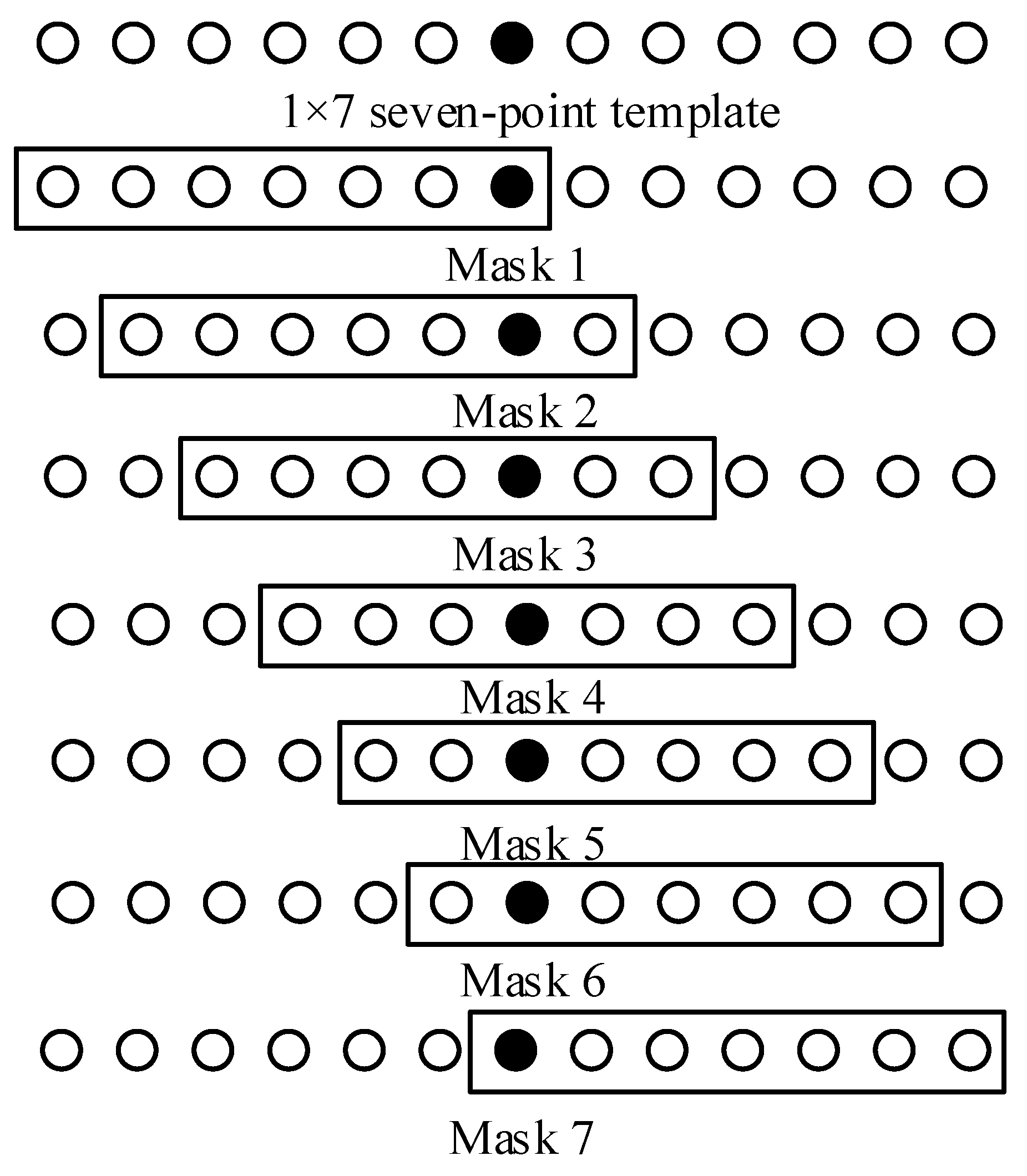
To address each point in the power quality signal, a 1 × 7 template and seven masks based on this template are designed. The MD of each point to these seven masks is calculated, and the mask with the highest MD is selected. The noise of this point is then reduced using the mean value of all points within the selected mask.
Since the collected power quality signal is a discrete digital sequence, for each point in this sequence, we consider it as the central point and design seven masks as shown in Figure 1. The small black dot represents the central point, and the small circles represent neighboring points. A 1 × 7 seven-point template is adopted, resulting in seven masks in total. The MD of each mask is then calculated. In fuzzy theory, the membership function determines the degree of membership of an element to a given set. In this case, the mask with the highest MD value is chosen because the data obtained after denoising with this mask are closest to the original data.
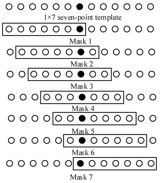
Figure 1.
Design structure of the discrete digital sequence mask.
Figure 1 illustrates the design structure of the discrete digital sequence mask. In the mask, if too few template points are used, the correlation between the time sequence information of the digital signal and the signal points will be ignored, resulting in an insignificant denoising effect. However, if too many template points are used, the information for the abrupt point will be affected and the abrupt point will be smoothed, thus affecting the detection of the abrupt point and the calculation efficiency. Therefore, this paper comprehensively compares the results of a 1 × 3 three-point template, 1 × 5 five-point template, 1 × 7 seven-point template, and 1 × 9 nine-point template, and proves that the best effect is obtained using 7 points in each mask.
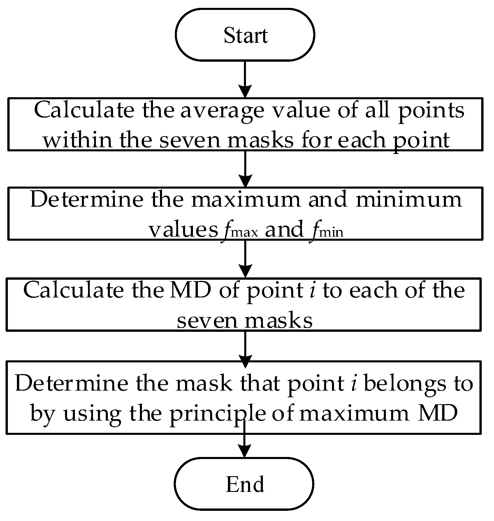
The denoising steps based on the improved fuzzy logic theory are as follows:
(1) Calculate the average value of all points within the seven masks centered at point i:
where represent the mean value of points within each mask, and represent the points of the discrete digital sequence.
(2) Determine the maximum and minimum values fmax and fmin among all 13 points within the seven masks centered at point i:
where fmax and fmin represent the maximum and minimum values of the points in the discrete digital sequence.
(3) Calculate the MD of point i to each of the seven masks:
where gm(i) is the MD of point i to the m-th mask; um is the average value of points within the m-th mask; and f(i) is the value of the central point.
(4) Determine the mask that point i belongs to by using the principle of maximum MD: Assuming that ux is the maximum value among u1 to u7, the point can be judged to belong to the x-th mask based on the principle of maximum MD.
(5) Repeat the above process for all points in the digital sequence until completion.
The calculation steps of the designed mask are shown in Figure 2.
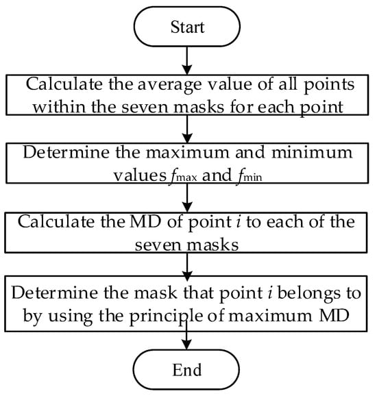
Figure 2.
The calculation steps of the designed mask.
4. The Fuzzification Process and Parameter Coordination of FL Theory
4.1. The Fuzzification Process
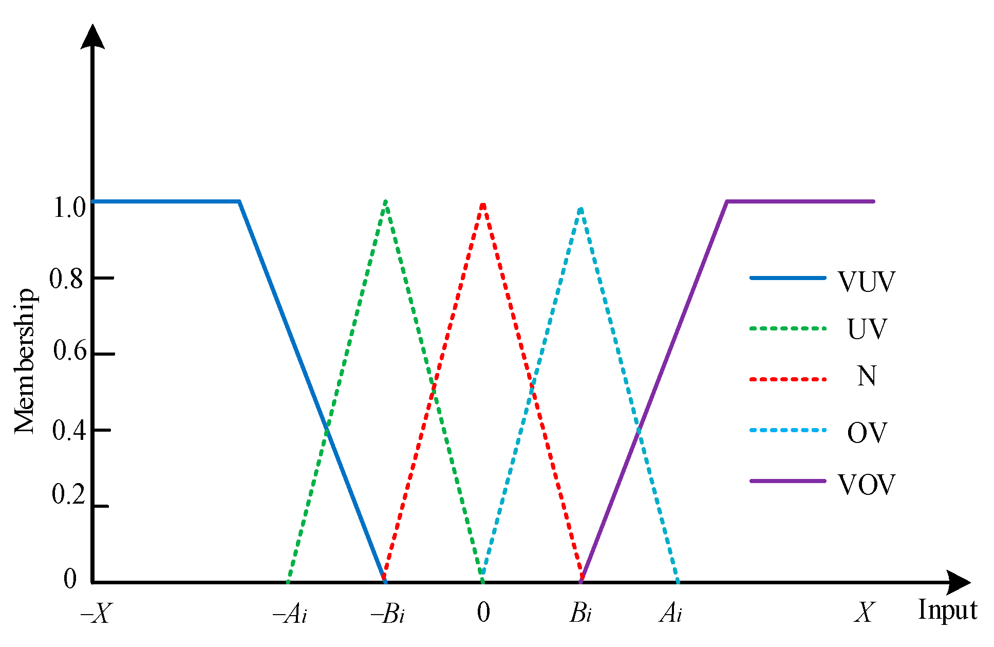
During the fuzzification process, each input is assigned its own fuzzy membership function (FMF). For the sake of simplicity, all inputs utilize triangular functions as their FMFs. Figure 3 illustrates the membership functions of these inputs.
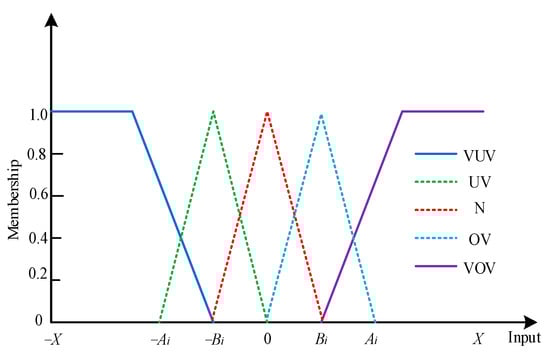
Figure 3.
The membership function of the inputs.
In this paper, since the application of fuzzy logic theory necessitates the construction of membership functions, for the sake of simplicity, triangular functions are employed to represent all the fuzzy membership functions for input and output variables. When using triangular functions for representation, the current convention typically adopts five fuzzy subsets. Therefore, this paper also adopts five fuzzy subsets for representation: the lower input set (VUV), the low input set (UV), the normal input set (N), the high input set (OV), and the higher input set (VOV). In Figure 3, the input domain is depicted as [−X, X], where X represents the maximum possible deviation of the input. For each input i, Ai denotes the boundary parameter (BP) within the fuzzy subsets OV and UV, while Bi represents the BP within the fuzzy subsets VUV, N, and VOV. By coordinating Ai and Bi, the maximum utilization of the inputs is achieved.
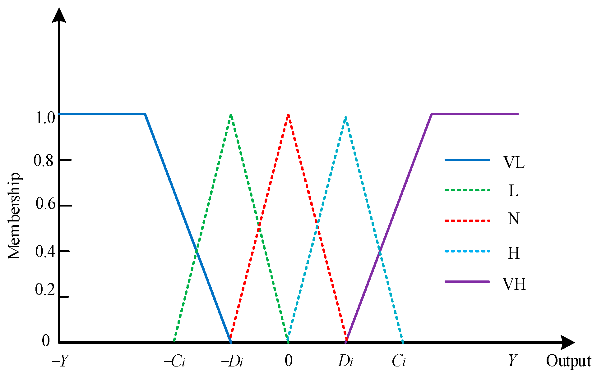
Figure 4 displays the membership functions of the outputs. Given the varying degrees of influence the outputs have on the results, five fuzzy subsets are selected for the outputs as well: the sharp drop set (VL), the drop set (L), the normal fluctuation set (N), the rise set (H), and the sharp rise set (VH). The domain of the outputs is [−Y, Y], where Y signifies the maximum possible output. For each output i, Ci denotes the BP within the fuzzy subsets H and L, while Di represents the BP within the fuzzy subsets VH, N, and VL. By coordinating Ci and Di, the maximum utilization of the outputs is achieved.
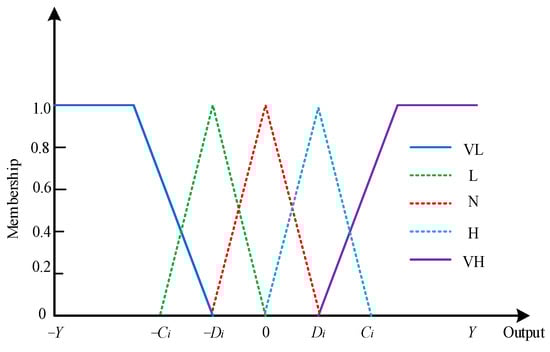
Figure 4.
The membership function of the outputs.
4.2. Parameter Coordination
- (1)
- Coordinated design of parameters Ai and Bi in the membership function
Assuming that the maximum input of xi is , the regulation of each input accounts for the same proportion of its maximum; assume the proportion is α, which can be expressed as follows:
where is the maximum deviation of the input xn, and An is the BP value of fuzzy subsets OV and UV.
Then, the BP Ai of input xi can be obtained, which can be expressed as follows:
where represents the maximum deviation of bus xi, and represents the maximum input of xj.
According to the BPs An and Bn of the input xn, the BP Bi can be determined, which can be expressed as follows:
- (2)
- Coordinated design of parameters Ci and Di in the membership function
Similarly, assuming that the maximum output of yi is , the regulation of each output accounts for the same proportion of its maximum; assume the proportion is β, which can be expressed as follows:
where is the maximum deviation of the output yn, and Cn is the BP value of fuzzy subsets L and H.
Then, the BP Ci of output yi can be obtained, which can be expressed as follows:
where represents the maximum deviation of output yi, and represents the maximum output of yj.
According to the BPs Cn and Dn of the output yn, the BP Ci can be determined, which can be expressed as follows:
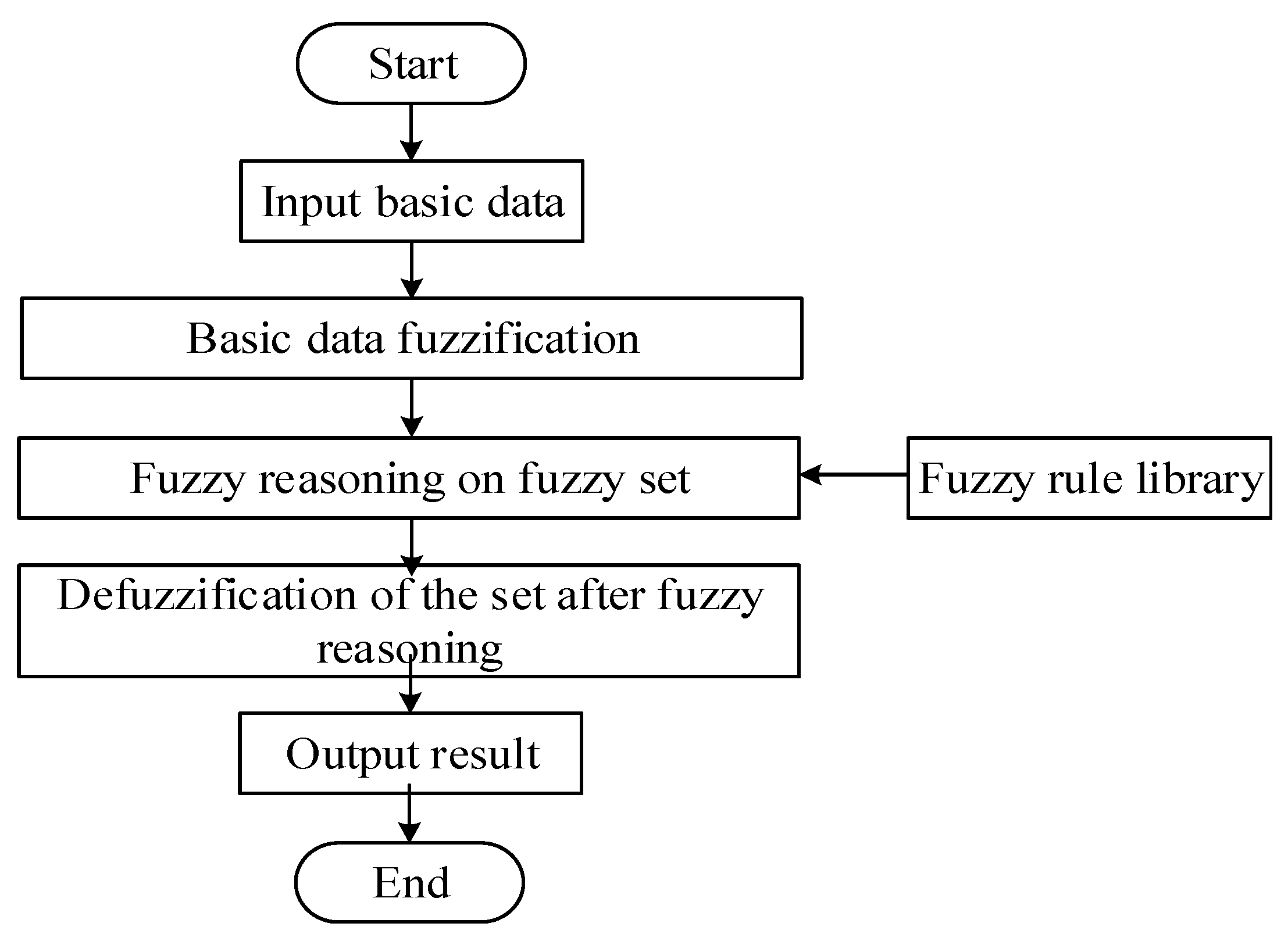
The specific steps of fuzzy logic theory [12,13,14,15,16] are as follows:
- (1)
- Input basic data;
- (2)
- Fuzzy processing of accurate data and conversion into fuzzy data;
- (3)
- The fuzzy data set is mapped to a specific output fuzzy set through fuzzy rules;
- (4)
- Deal with the fuzzy set, and the fuzzy conclusion is transformed into specific precise values.
The calculation process is shown in Figure 5. In this paper, input refers to the power quality signal sequence.
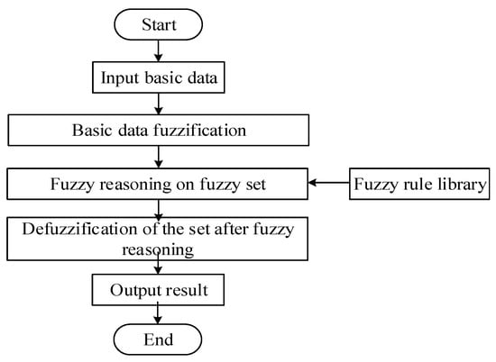
Figure 5.
The flow chart of fuzzy logic theory.
5. Numerical Test and Analysis
As there are many kinds of power quality phenomena in a power system, it is thus impossible to list them one by one. In order to verify the effectiveness of the proposed method, this paper simulates two common power quality phenomena: short-time voltage sag signal and voltage interruption signal, and compares the simulation results with the traditional filtering algorithms. The simulation environment is based on MATLAB R2014a.
5.1. Comparison of Voltage Sag Signal Processing
Voltage sag signal: The single-phase voltage root mean square (RMS) value is 220 V, and the frequency is 50 Hz (i.e., the period is 20 ms). A voltage sag of 20% with a 60-degree phase jump occurs at 40~80 ms, and the voltage during the sag is sinusoidal; this signal is referred to as the original ideal signal. In this paper, Gaussian white noise is used as the simulation noise; it has a mean of 0 and a variance of 0.06. Filtering factor is chosen as 0.05. In this paper, the original input is Gaussian noise superimposed on the assumed truth value. Therefore in this paper, no additional preprocessing method is used to process the input data. The noisy signal waveform is depicted in Figure 6.
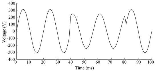
Figure 6.
Voltage sag signal with phase jump and Gaussian white noise.
A comparison is made between the method proposed in this paper and seven other algorithms to demonstrate the denoising effect of the proposed method. The other seven algorithms compared with the method proposed in this paper are as follows: traditional mean filtering method, traditional median filtering method, fuzzy mean filtering method, fuzzy median filtering method, a 1 × 3 three-point template based on fuzzy logic parameter coordination, a 1 × 5 five-point template based on fuzzy logic parameter coordination, and a 1 × 9 nine-point template based on fuzzy logic parameter coordination.
Based on the requirements of power quality denoising in terms of signal smoothness and preservation of mutation points, the simulation experiment analysis is divided into two main parts: Firstly, the signal-to-noise ratio (SNR) is calculated to describe and compare the denoising smoothness from the data. This part mainly focuses on the requirement of denoising signal smoothness: the greater the SNR, the better the smoothness. Secondly, to illustrate the preservation of mutation points, the amplitudes of mutation points before and after denoising can be obtained, and the closeness of the denoised amplitude to the ideal state can be compared. The signal sag interval is t ∈ [40 ms, 80 ms].
To more effectively demonstrate the denoising effect and compare the denoising accuracy of each algorithm, the SNR is introduced, defined as follows:
where represents the SNR before denoising; is the SNR after denoising, and the greater the SNR, the better the denoising effect; L represents the signal length, i.e., the number of signal points; n is the position of the signal point; is the original signal value at the n-th point; x(n) represents the value after adding noise; represents the value after denoising. The greater the SNR, the better the smoothness.
The SNR of the voltage sag signal after adding noise and denoising by using the following nine algorithms is calculated, and the results are shown in Table 1.

Table 1.
Comparison of SNR of voltage sag signals.
From Table 1, it can be seen that the SNR of the ideal signal after adding noise is 20.3394. The SNR of the traditional mean filtering method is 22.9976; the SNR of the traditional median filtering method is 23.2964; the SNR of the fuzzy mean filtering method is 24.3576; the SNR of the fuzzy median filtering method is 25.1762; the SNR of a 1 × 3 three-point template based on fuzzy logic parameter coordination is 25.3328; the SNR of a 1 × 5 five-point template based on fuzzy logic parameter coordination is 26.1794; the SNR of a 1 × 9 nine-point template based on fuzzy logic parameter coordination is 25.4561; and the SNR of the proposed method is 27.5183. Therefore, the denoising capability of the algorithm proposed in this paper is superior to the other seven filtering algorithms. In addition, the use of the 1 × 7 seven-point template in this paper is the best, compared with the use of a 1 × 3 three-point template, 1 × 5 five-point template, and 1 × 9 nine-point template based on fuzzy logic parameter coordination.
To further compare the preservation of mutation point information, the ideal amplitude and denoised amplitude of the mutation points are obtained, and the denoising amplitude difference is calculated by using the following formula:
where represents the difference between denoising amplitude and the ideal amplitude. The smaller the value of , the lower the degree of mutation.
The results of the difference between denoising amplitude and the ideal amplitude are shown in Table 2.
Table 2.
Comparison of the difference between denoising amplitude and the ideal amplitude of the voltage sag signal.
From the results in Table 2, it can be seen that for both mutation point 1 and mutation point 2, the of the ideal signal after adding noise is 30.7745 and 45.7658; the of the traditional mean filtering method is 29.3268 and 43.2896; the of the traditional median filtering method is 27.8357 and 37.5762; the of the fuzzy mean filtering method is 22.6638 and 32.2864; the of the fuzzy median filtering method is 17.8395 and 27.1775; the of a 1 × 3 three-point template based on fuzzy logic parameter coordination is 17.2465 and 26.5437; the of a 1 × 5 five-point template based on fuzzy logic parameter coordination is 16.4487 and 25.3398; the of a 1 × 9 nine-point template based on fuzzy logic parameter coordination is 17.2631 and 26.1742; and the of the proposed method is 15.2283 and 24.3796. Therefore, the of the proposed method in this paper is the smallest, and the denoised signal amplitude is closest to the value of the original ideal signal. In addition, the use of the 1 × 7 seven-point template in this paper is also the best, compared with the use of a 1 × 3 three-point template, 1 × 5 five-point template, and 1 × 9 nine-point template based on fuzzy logic parameter coordination.
5.2. Comparison of Voltage Interruption Signal Processing
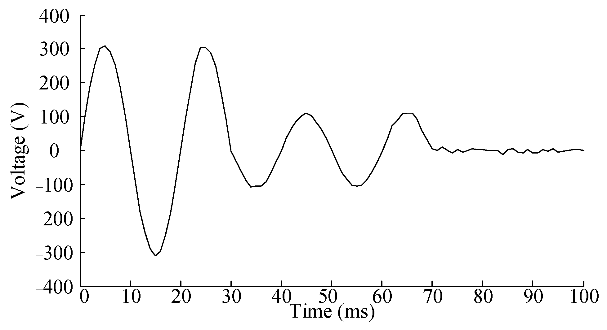
Voltage interruption signal: the single-phase voltage RMS value is 220 V and the frequency is 50 Hz (i.e., the period is 20 ms). Starting from 30 ms, a 60-degree phase jump and a 30% voltage sag occur at the sampling points. From 70 ms onward, the system enters a short-term interruption. Gaussian white noise with a mean of 0 and a variance of 0.06 is introduced. The noisy signal waveform is depicted in Figure 7.

Figure 7.
Voltage interruption signal with phase jump and Gaussian white noise.
The SNR of the voltage interruption signal after adding noise and denoising by using the following nine algorithms is calculated, and the results are shown in Table 3.
Table 3.
Comparison of the SNR of voltage interruption signals.
From Table 3, it can be seen that the SNR of the ideal signal after adding noise is 27.0157; the SNR of the traditional mean filtering method is 27.8994; the SNR of the traditional median filtering method is 28.4173; the SNR of the fuzzy mean filtering method is 29.2576; the SNR of the fuzzy median filtering method is 30.2865; the SNR of a 1 × 3 three-point template based on fuzzy logic parameter coordination is 30.4677; the SNR of a 1 × 5 five-point template based on fuzzy logic parameter coordination is 30.7342; the SNR of a 1 × 9 nine-point template based on fuzzy logic parameter coordination is 30.2689; and the SNR of the proposed method is 31.2368. Therefore, the denoising capability of the proposed method is significantly better than that of the other eight algorithms. In addition, the use of the 1 × 7 seven-point template in this paper is also the best, compared with the use of a 1 × 3 three-point template, 1 × 5 five-point template, and 1 × 9 nine-point template based on fuzzy logic parameter coordination.
The results of the difference between denoising amplitude and the ideal amplitude are shown in Table 4.
Table 4.
Comparison of the difference between denoising amplitude and the ideal amplitude of the voltage interruption signal.
From the results in Table 4, it can be seen that for both mutation point 1 and mutation point 2, the of the ideal signal after adding noise is 37.6824 and 41.3376; the of the traditional mean filtering method is 22.3765 and 25.5268; the of the traditional median filtering method is 15.5766 and 17.6627; the of the fuzzy mean filtering method is 12.4864 and 14.3892; the of the fuzzy median filtering method is 9.5573 and 10.1124; the of a 1 × 3 three-point template based on fuzzy logic parameter coordination is 9.1762 and 9.4354; the of a 1 × 5 five-point template based on fuzzy logic parameter coordination is 8.5467 and 8.8873; the of a 1 × 9 nine-point template based on fuzzy logic parameter coordination is 8.9972 and 9.2265; and the of the proposed method is 7.3149 and 8.5567. Therefore, the of the proposed method in this paper is the smallest, and the denoised signal amplitude is closest to the value of the original ideal signal. In addition, the use of the 1 × 7 seven-point template in this paper is still the best, compared with the use of a 1 × 3 three-point template, 1 × 5 five-point template, and 1 × 9 nine-point template based on fuzzy logic parameter coordination.
Based on the above analysis, it can be concluded that the proposed algorithm outperforms the other seven algorithms in terms of both denoising capability and mutation point preservation. It is more suitable for denoising power quality signals and demonstrates excellent performance.
6. Conclusions
According to the denoising requirements of power quality signals, by using the relevant knowledge in a fuzzy field, a denoising method of a power quality signal based on parameter coordination of membership function in fuzzy logic theory is proposed in this paper. To make the best use of the signal sequence information of power quality, seven masks are designed, and the corresponding membership degrees are calculated for these seven masks based on fuzzy logic theory, where the average value of all points in these masks is used as the input of fuzzy logic theory. To achieve the maximum utilization of the power signal, the boundary parameters of membership function in fuzzy logic theory are designed harmoniously. Experimental simulation is carried to verify the effectiveness of the proposed method. Through simulation analysis, compared with the traditional mean filtering algorithm, median filtering algorithm, fuzzy mean filtering algorithm, and median filtering algorithm, 1 × 3 three-point template, 1 × 5 five-point template, and 1 × 9 nine-point template based on fuzzy logic parameter coordination, the proposed method has outstanding advantages in power quality signal processing, which can not only effectively eliminate large-area noise but also retain the mutation point information to the greatest extent.
In the field of power quality analysis, the method proposed in this paper can be applied to related filters and power quality monitoring devices. By filtering out harmonics through filters, the damage caused by these harmonics to power equipment can be reduced, thereby extending the service life of the equipment, lowering maintenance costs, decreasing reactive power losses, and improving power utilization efficiency. Power quality monitoring devices can monitor the operating state of the power system in real time, promptly detecting issues such as voltage fluctuations, drops, swells, imbalances, and harmonics, thus providing important data support for power quality analysis and management.
Author Contributions
Conceptualization, R.Y., H.B., Y.Z., B.C. and H.Z.; methodology, R.Y., H.B., Y.Z., B.C. and H.Z.; software, R.Y., H.B., Y.Z., B.C. and H.Z.; writing—original draft preparation, R.Y., H.B., Y.Z., B.C. and H.Z. All authors have read and agreed to the published version of the manuscript.
Funding
This research is funded by the Southern Power Grid Corporation Technology Project (No. 00000KC23050049).
Data Availability Statement
The original contributions presented in this study are included in the article.
Conflicts of Interest
Authors Ruotian Yao and Hao Bai were employed by China Southern Power Grid Electric Power Research Institute. Author Yifan Zhang was employed by Inner Mongolia Key Laboratory of Smart Grid of New-Type Power System. Author Baoyi Cen was employed by CET Electric Technology Inc. The remaining author declares that the research was conducted in the absence of any commercial or financial relationships that could be construed as a potential conflict of interest.
References
- Tong, H.; Zeng, X.; Yu, K.; Zhou, Z. A Fault Identification Method for Animal Electric Shocks Considering Unstable Contact Situations in Low-Voltage Distribution Grids. IEEE Trans. Ind. Inform. 2025. [Google Scholar] [CrossRef]
- Ge, Y.; Hu, H.; Huang, Y.; Wang, K.; Chen, J.; He, Z. Quadratic Sensitivity Models for Flexible Power Quality Improvement in AC Electrified Railways. IEEE Trans. Power Electron. 2023, 38, 2844–2849. [Google Scholar] [CrossRef]
- Li, H.; Li, B.; Luo, Z.; Li, H.; Zhao, Y.; Wang, T.; Sun, Y. Power Supply Reliability Enhancement for Low-Voltage Distribution Area with Power Quality Improvement Function. IEEE Access 2022, 10, 130619–130631. [Google Scholar] [CrossRef]
- Lai, J.; Chen, M.; Dai, X.; Zhao, N. Energy Management Strategy Adopting Power Transfer Device Considering Power Quality Improvement and Regenerative Braking Energy Utilization for Double-Modes Traction System. CPSS Trans. Power Electron. Appl. 2022, 7, 103–111. [Google Scholar] [CrossRef]
- Wang, J.; Sun, K.; Wu, H.; Zhang, L.; Zhu, J.; Xing, Y. Quasi-Two-Stage Multifunctional Photovoltaic Inverter with Power Quality Control and Enhanced Conversion Efficiency. IEEE Trans. Power Electron. 2020, 35, 7073–7085. [Google Scholar] [CrossRef]
- Heenkenda, A.; Elsanabary, A.; Seyedmahmoudian, M.; Mekhilef, S.; Stojcevski, A.; Aziz, N.F.A. Unified Power Quality Conditioners Based Different Structural Arrangements: A Comprehensive Review. IEEE Access 2023, 11, 43435–43457. [Google Scholar] [CrossRef]
- Ray, P.; Ray, P.K.; Dash, S.K. Power Quality Enhancement and Power Flow Analysis of a PV Integrated UPQC System in a Distribution Network. IEEE Trans. Ind. Appl. 2022, 58, 201–211. [Google Scholar] [CrossRef]
- de Vasconcelos, F.M.; Rocha, C.H.S.; Almeida, C.F.M.; Pereira, D.D.S.; Rosa, L.H.L.; Kagan, N. Methodology for Inspection Scheduling in Power Distribution Networks Based on Power Quality Indexes. IEEE Trans. Power Deliv. 2021, 36, 1211–1221. [Google Scholar] [CrossRef]
- Alonso, A.M.D.S.; Arenas, L.D.O.; Bonaldo, J.P.; Olímpio Filho, J.D.A.; Marafão, F.P.; Paredes, H.K.M. Power Quality Improvement in Commercial and Industrial Sites: An Integrated Approach Mitigating Power Oscillations. IEEE Access 2024, 12, 50872–50884. [Google Scholar] [CrossRef]
- Xia, Y.; Li, Z.; Xi, Y.; Wu, G.; Peng, W.; Mu, L. Accurate Fault Location Method for Multiple Faults in Transmission Networks Using Travelling Waves. IEEE Trans. Ind. Inform. 2024, 20, 8717–8728. [Google Scholar] [CrossRef]
- Zhao, T.; Cao, H.; Dian, S. A Self-Organized Method for a Hierarchical Fuzzy Logic System Based on a Fuzzy Autoencoder. IEEE Trans. Fuzzy Syst. 2022, 30, 5104–5115. [Google Scholar] [CrossRef]
- Nguyen, L.A.; Nguyen, N.T. Logical Characterizations of Crisp Bisimulations in Fuzzy Description Logics. IEEE Trans. Fuzzy Syst. 2023, 31, 1294–1304. [Google Scholar] [CrossRef]
- Badia, G.; Noguera, C. A 0–1 Law in Mathematical Fuzzy Logic. IEEE Trans. Fuzzy Syst. 2022, 30, 3833–3840. [Google Scholar] [CrossRef]
- Singh, D.J.; Verma, N.K.; Ghosh, A.K.; Malagaudanavar, A. An Approach Towards the Design of Interval Type-3 T–S Fuzzy System. IEEE Trans. Fuzzy Syst. 2022, 30, 3880–3893. [Google Scholar] [CrossRef]
- Kamthan, S.; Singh, H. Hierarchical Fuzzy Logic for Multi-Input Multi-Output Systems. IEEE Access 2020, 8, 206966–206981. [Google Scholar] [CrossRef]
- Guo, T.; Zhang, T.; Lim, E.; López-Benítez, M.; Ma, F.; Yu, L. A Review of Wavelet Analysis and Its Applications: Challenges and Opportunities. IEEE Access 2022, 10, 58869–58903. [Google Scholar] [CrossRef]
- Zhen, P.; Zhang, B.; Chen, Z.; Guo, D.; Ma, W. Spectrum Sensing Method Based on Wavelet Transform and Residual Network. IEEE Wirel. Commun. Lett. 2022, 11, 2517–2521. [Google Scholar] [CrossRef]
- Mukherjee, N.; Chattopadhyaya, A.; Chattopadhyay, S.; Sengupta, S. Discrete-Wavelet-Transform and Stockwell-Transform-Based Statistical Parameters Estimation for Fault Analysis in Grid-Connected Wind Power System. IEEE Syst. J. 2020, 14, 4320–4328. [Google Scholar] [CrossRef]
- Singh, G.; Chiluveru, S.R.; Raman, B.; Tripathy, M.; Kaushik, B.K. Novel Architecture for Lifting Discrete Wavelet Packet Transform with Arbitrary Tree Structure. IEEE Trans. Very Large Scale Integr. (VLSI) Syst. 2021, 29, 1490–1494. [Google Scholar] [CrossRef]
- Xu, Y.; Lu, W.; Li, C.; Aslam, W. Sensitivity of Low-Voltage Variable-Frequency Devices to Voltage Sags. IEEE Access 2019, 7, 2068–2079. [Google Scholar] [CrossRef]
- Shi, J.; Chen, G.; Zhao, Y.; Tao, R. Synchrosqueezed Fractional Wavelet Transform: A New High-Resolution Time-Frequency Representation. IEEE Trans. Signal Process. 2023, 71, 264–278. [Google Scholar] [CrossRef]
- Gyanendra; Chiluveru, S.R.; Raman, B.; Tripathy, M.; Kaushik, B.K. Memory Efficient Architecture for Lifting-Based Discrete Wavelet Packet Transform. IEEE Trans. Circuits Syst. II Express Briefs 2021, 68, 1373–1377. [Google Scholar] [CrossRef]
- Tian, Y.; Gao, J.; Wang, D. Synchrosqueezing Optimal Basic Wavelet Transform and Its Application on Sedimentary Cycle Division. IEEE Trans. Geosci. Remote Sens. 2022, 60, 1–13. [Google Scholar] [CrossRef]
- Li, M.; Xu, R.; Chen, Q. A Partial Order OWA Operator for Solving the OWA Weighing Dilemma. IEEE Access 2023, 11, 55435–55441. [Google Scholar] [CrossRef]
- Onar, S.; Ersoy, B.A.; Hila, K.; Davvaz, B. T-Fuzzy Subhypernear-Modulesin. Fuzzy Inf. Eng. 2023, 15, 162–182. [Google Scholar] [CrossRef]
- She, R.; Qian, H.; Wang, Z. A New ACD-OMP Accelerator with Clustered Computing Look-Ahead. IEEE Trans. Very Large Scale Integr. (VLSI) Syst. 2023, 31, 1449–1453. [Google Scholar] [CrossRef]
- Bartz, H.; Jerkovits, T.; Puchinger, S.; Rosenkilde, J. Fast Decoding of Codes in the Rank, Subspace, and Sum-Rank Metric. IEEE Trans. Inf. Theory 2021, 67, 5026–5050. [Google Scholar] [CrossRef]

Disclaimer/Publisher’s Note: The statements, opinions and data contained in all publications are solely those of the individual author(s) and contributor(s) and not of MDPI and/or the editor(s). MDPI and/or the editor(s) disclaim responsibility for any injury to people or property resulting from any ideas, methods, instructions or products referred to in the content. |
© 2025 by the authors. Licensee MDPI, Basel, Switzerland. This article is an open access article distributed under the terms and conditions of the Creative Commons Attribution (CC BY) license (https://creativecommons.org/licenses/by/4.0/).