1. Introduction
Gas-liquid two-phase spiral pipeline flow involves three-dimensional rotational motion characterized by two velocities: axial velocity and tangential (or circumferential) velocity [
1]. This type of flow has wide-ranging applications across industries, including hydraulic transportation, combustion technology, hydrocyclone separation, fluid mechanics, and machinery. Research on gas-liquid two-phase spiral flows has focused on flow pattern transitions and pressure drop characteristics [
2,
3,
4]. These flows are typically induced by cyclone makers, which can include vane-type, guide-vane-type, and tangential-streaming cyclone makers [
5].
Natural gas hydrates, formed from natural gas and methane under high pressure and low temperature, rely on the gas-liquid contact area as a critical factor for their formation. Surfactants significantly influence the flow patterns of gas-liquid two-phase flows. Studying the behavior of multiphase flows with surfactants is vital for understanding hydrate transport in pipelines. Recent work by the Gas Hydrate Research Center at Changzhou University, led by Professor Wang Shuli [
6], has thoroughly examined the characteristics of gas-liquid two-phase spiral flows induced by spiral metallic vanes or twisted spiral tapes. Their findings indicate that natural gas hydrates are more likely to form in spiral dispersed flow patterns due to the larger gas-liquid contact area, improved mixing, and enhanced mass transfer rates. Moreover, the pressure drop is minimized in spiral dispersed flow, increasing the overpressure available to promote hydrate formation. Consequently, spiral dispersed flow patterns may play a critical role in facilitating natural gas hydrate production and transportation. An experimental apparatus for studying hydrate formation within gas-liquid two-phase spiral pipeline systems has also been successfully developed.
Surfactants are amphiphilic compounds with hydrophilic and lipophilic components that reduce surface tension at the gas-liquid interface [
7]. In low-concentration surfactant solutions (concentration is less than 100 mg/kg), surface tension is significantly reduced, increasing gas solubility in the liquid phase and enhancing gas-liquid mixing. This strongly influences flow characteristics, including flow pattern transitions and pressure drops [
8]. Research by Hand et al. [
9] on air-liquid two-phase flows with low concentrations of SDS solution in horizontal pipelines (0.0935 m diameter) demonstrated these effects. Hanratty et al. [
10] reported that surfactant solutions mitigate wave formation in square tubes, while Spedding et al. [
11] found that surfactants eliminate gravitational waves, promoting smoother stratified flows. Kang et al. [
12] investigated drag reducers’ effects on oil-gas-liquid three-phase flow in inclined pipelines, observing that stratified flow transitions to slug flow only at high liquid-phase velocities. Kok [
13] demonstrated the onset conditions of flow separation and the relationship between the axial and secondary flow fields in the T-junction. The strength and the structures of the vortical cells are correlated with the balance between the centrifugal forces and the transverse pressure gradient at the junction.
Natural gas hydrates were first identified in 1810 [
14]. These hydrates have an exceptionally high storage density, with 160–180 standard volumes of natural gas stored per unit volume of solid hydrate [
15,
16]. They are recognized for their efficiency, safety, and cost-effectiveness, making them a promising alternative energy source to traditional fossil fuels [
17,
18]. Commercial storage and transportation of natural gas using hydrate technology offer substantial advantages [
19,
20]. However, industrial adoption is limited by insufficient gas-liquid contact and slow hydrate formation rates [
21].
Based on the aforementioned literature survey, while considerable progress has been made in studying flow pattern maps for gas-liquid two-phase flows, especially in horizontal pipelines, research on spiral flow patterns, flow maps, and transition rules remains insufficient as reported on
Table 1.
This paper experimentally investigates the effect of surface tension on gas-liquid two-phase spiral flows in horizontal pipelines using low-concentration sodium dodecyl sulfate (SDS) solutions. An experimental apparatus was developed, comprising a liquid-phase circulation system, a gas-phase supply system, spiral vanes, and a transparent experimental tube, to study the flow patterns and transitions induced by SDS. Four distinct flow patterns—spiral linear flow, spiral wave-stratified flow, spiral axial flow, and spiral dispersed flow—were identified and analyzed, with particular focus on the transitions between these patterns as influenced by variations in surface tension and phase velocities. A flow pattern map was developed to visualize and predict the behavior of gas-liquid two-phase spiral flows under surfactant conditions. Also, the effects of flow characteristics, including surface tension reduction, velocity variations, and pressure drop, were comprehensively studied to provide insights into optimizing hydrate slurry transport and multiphase flow applications.
This paper includes the following novel contributions. Firstly, while previous studies have investigated gas-liquid two-phase flows, the effect of surface tension on spiral flows induced by surfactants has not been systematically addressed. This study introduces a novel focus on flow pattern transitions in horizontal pipelines with SDS solutions. Secondly, a detailed experimental apparatus was designed to observe the deformation and evolution of spiral flow patterns, allowing for precise characterization of flow pattern transitions and their relationship to surface tension variations. Lastly, a new flow pattern map was constructed to predict transitions in gas-liquid spiral flows, providing critical insights into optimizing hydrate slurry spiral flow technology.
Table 1.
Research development of spiral flow.
Table 1.
Research development of spiral flow.
| | Date | Author | Research Achievement | Reference |
|---|
| The Effect of Surface Tension on Flow Pattern Hoid-Up and Pressure Drop during Horizontal Air/Water Pipe Flow at Atmospheric Conditions | 1992.04 | Hand N P, Spedding P L, Ralph S J | Flow characteristics of air-liquid two-phase flow with a low concentration of SDS solution in a horizontal pipeline with 0.0935 m diameter were investigated. | [9] |
| Initiation of Roll Waves | 1961.09 | Hanratty T J, Hershman A | It is found that the surfactant solution can affect the flow characteristics of the gas-liquid two-phase flow in the square tube and the surfactant solution can counteract the gas-liquid two-phase flow. | [10] |
| A Revised Analysis of the Effect of Surfactants on Two-Phase Phenomena in Horizontal Air-Water Pipe Flow | 2008.05 | Spedding P L, Hand N P | Influence effects on the law of gas-liquid two-phase flow patterns in horizontal pipeline by surfactant solution has been researched and it was found that gravitational wave could be canceled by surfactant solution, then the flow pattern of smooth stratified flow will produce more frequently. | [11] |
| Effect of Drag-Reducing Agents in Multiphase Flow Pipelines | 1998.03 | Kang C, Vancko R M, Green A S | Influence effects on the law of oil-gas-liquid three-phase flow patterns in inclined pipeline by drag reducer has been researched and it was found that the flow pattern of stratified flow will not transfer into the flow pattern of slug flow until the velocity of liquid phase is very high. | [12] |
| Experimental study on gas-liquid two-phase spiral flow in a horizontal pipe under a degradable surfactant system | 2016 | Dai Yuan, Rao Yongchao, Wang Shuli | Experimental research was conducted on the gas-liquid two-phase spiral flow pattern in a horizontal tube under the influence of surfactants and found that the addition of surfactants can change the transition boundary of the flow pattern. | [13] |
| Formation, Exploration, and Development of Natural Gas Hydrates | 2022 | Dong Hongsheng, Zhang Lunxiang, Wang Jiaqi | The study of multiphase flow pattern is the basis of safe transportation of hydrate extraction. | [16] |
| Experimental study on synergistic promotion of reciprocating impact and porous materials on methane capture based on hydrate method | 2024 | Hu J, Chen N, Li Z | The experimental results indicate that under the reciprocating impact, adding a small amount of ZIF-8 or activated carbon particles in water can improve the methane capture capacity of hydrate when the initial pressure is less than 5 MPa and shorten the equilibrium time of the reaction at high pressure. | [17] |
2. Experiment Device and Method
2.1. Experimental Device
This research utilized a gas-liquid two-phase spiral pipeline flow experimental apparatus to systematically investigate the flow characteristics of such flows in low-concentration surfactant solutions. The experimental setup comprises a liquid-phase circulation system, a gas-phase supply system, an experimental tube, and a data acquisition system, as illustrated in
Figure 1.
The liquid-phase circulation system consists of a single water pump, water pipeline, and liquid-phase flowmeter. The water pump has a rated flow of 15 m3/h, an output power of 0.75 kW, and a maximum experimental flow rate of 3.7 m3/h. The liquid-phase flowmeter has a measuring range of 0.6–6 m3/h with an accuracy grade of 2.5. The gas-phase supply system includes an air compressor, gas pipeline, and gas-phase flowmeter. The air compressor generates an exhaust pressure of 0.9 MPa and is paired with a gas storage tank with a capacity of 23 L. Operating at a rated speed of 120 rpm, the air compressor has an output power of 1.5 kW. The gas-phase flowmeter has a measuring range of 0.2–4.0 m3/h. The experimental tube is made of transparent organic glass, with a diameter of 23 mm and a length of 2 m, allowing for clear observation of the flow phenomena. To eliminate refraction and ensure high-quality visualization, the tube is placed inside a cuboidal glass box filled with distilled water. The experimental phenomena are using a Sony HDR-XR550E high-definition hard disk camera, which has an effective pixel resolution of 4.15 million, a shutter speed range of 1/6–1/1000 s, and a hard disk storage capacity of 240 GB.
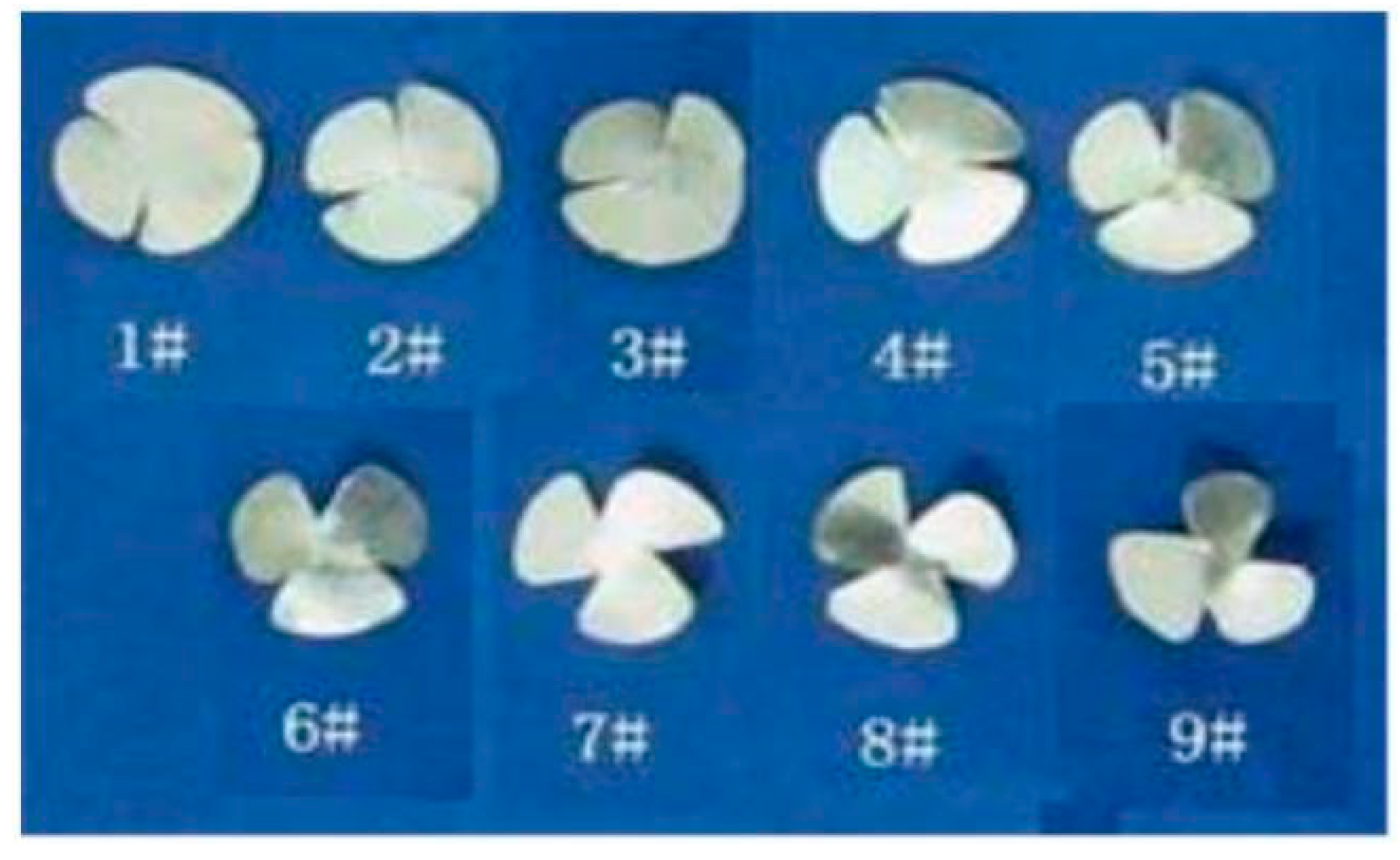
2.2. Spiral Vanes
In these experiments, water containing a low-concentration surfactant solution of SDS surfactant was transported from a tank to the experimental tube using a single-phase water pump, while air was simultaneously delivered to the experimental tube by an air compressor. The liquid-phase flow rate was measured and controlled by a liquid-phase flowmeter, while the gas-phase flow rate was similarly measured and controlled by a gas-phase flowmeter.
The cyclone makers used in the experiments were spiral vanes, with nine distinct types, as illustrated in
Figure 2. The structural characteristics of these spiral vanes are defined by two parameters: area and angle. The area is expressed as the ratio of the blade surface area to the total vane area, while the angle refers to the half-angle formed between two adjacent blades, as detailed in
Table 2.
Orthogonal tests were conducted using all nine vane types. The vane size is represented as the percentage of a single blade’s area relative to the total vane area, corresponding to 33.3%, 27.8%, and 22.2%. The spiral angle is defined as the angle between a single blade and the vane, calculated as half the angle between two adjacent blades. The spiral angles used in the experiments were 7.5°, 15°, and 22.5°.
The experimental materials consisted of a low-concentration anionic surfactant solution, sodium dodecyl sulfate (SDS), and air. The gas-liquid two-phase flow in the spiral pipeline was induced using spiral vanes. The representative spiral vanes selected for these experiments were types 2#, 4#, 5#, 6#, and 8#. In the experiments, the gas holdup ranged from 10% to 90%, with gas-phase velocities varying from 0 to 3.4 m/s and liquid-phase velocities ranging from 0 to 2.7 m/s. The SDS surfactant solution concentration was varied between 10 and 90 mg/kg.
During the experiments, the SDS surfactant solution was transported from the tank to the experimental tube via a water pump, while air was simultaneously delivered to the experimental tube using an air compressor. The liquid-phase flow was measured and regulated using a liquid-phase flowmeter, while the gas-phase flow was monitored and controlled with a gas-phase flowmeter. For each test, a specific liquid-phase velocity was held constant, while the gas-phase velocity was incrementally increased. During this process, the flow patterns of the gas-liquid two-phase spiral pipeline flow with the low-concentration SDS solution were observed, and the corresponding pressure drop was measured.
3. Results and Discussion
3.1. Flow Patterns
The six distinct flow patterns are typically observed in gas-liquid two-phase pipeline flows: bubble flow, plug flow, stratified flow, slug flow, wave flow, and annular flow. For gas-liquid two-phase spiral pipeline flows without surfactants, six flow patterns have been identified in our research: spiral bubbly flow, spiral slug flow, spiral linear flow, spiral wave stratified flow, spiral axial flow, and spiral dispersed flow [
22]. However, in gas-liquid two-phase spiral pipeline flows containing a low concentration of sodium dodecyl sulfate (SDS) solution, only four flow patterns are observed: spiral linear flow, spiral wave stratified flow, spiral axial flow, and spiral dispersed flow; the four flow patterns are shown in
Figure 3,
Figure 4,
Figure 5 and
Figure 6. Notably, spiral bubbly flow and spiral slug flow are absent under these conditions. The surfactant affects the surface tension of the gas-liquid two phase. The distribution of the gas-liquid interface of the slug flow is obvious. When the surface tension is reduced, the flow of the gas-liquid two phase is continuous.
The presence of SDS surfactant facilitates the occurrence of spiral dispersed flow in gas-liquid two-phase spiral pipeline flows. This phenomenon is attributed to the reduction in surface tension between the gas and liquid phases at low surfactant concentrations, which enhances gas solubility in the liquid phase and increases the degree of gas-liquid mixing.
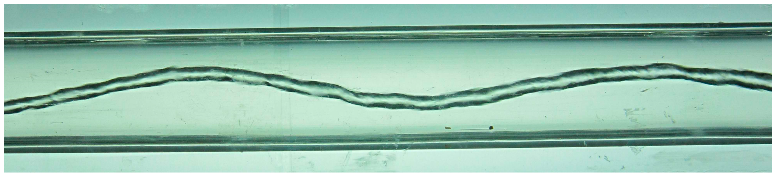
3.1.1. Spiral Linear Flow
This flow pattern formed under conditions where the velocities of the liquid and gas phases were relatively low. The gas phase appeared as a thinner gas plug, characterized by a generally large spiral amplitude, as illustrated in
Figure 3. For example, spiral linear flow was observed under specific conditions: using the 2# spiral vane, with an SDS solution concentration of 10 mg/kg, a liquid-phase velocity of 0.5 m/s, and a very low gas-phase velocity.
In this flow pattern, as the liquid-phase flow rate decreased while the gas-phase flow rate remained constant, the attenuation of the spiral pipeline flow became more pronounced, leading to a shorter length of the gas-liquid two-phase spiral flow. Conversely, when the gas-phase flow rate decreased while the liquid-phase flow rate was held constant, the spiral gas column fragmented into several sections.
Figure 3.
Spiral linear flow (spiral vane was 2#, the concentration of SDS was 10 mg/kg, the velocity of liquid phase was 0.5 m/s, the velocity of gas phase was very low).
Figure 3.
Spiral linear flow (spiral vane was 2#, the concentration of SDS was 10 mg/kg, the velocity of liquid phase was 0.5 m/s, the velocity of gas phase was very low).
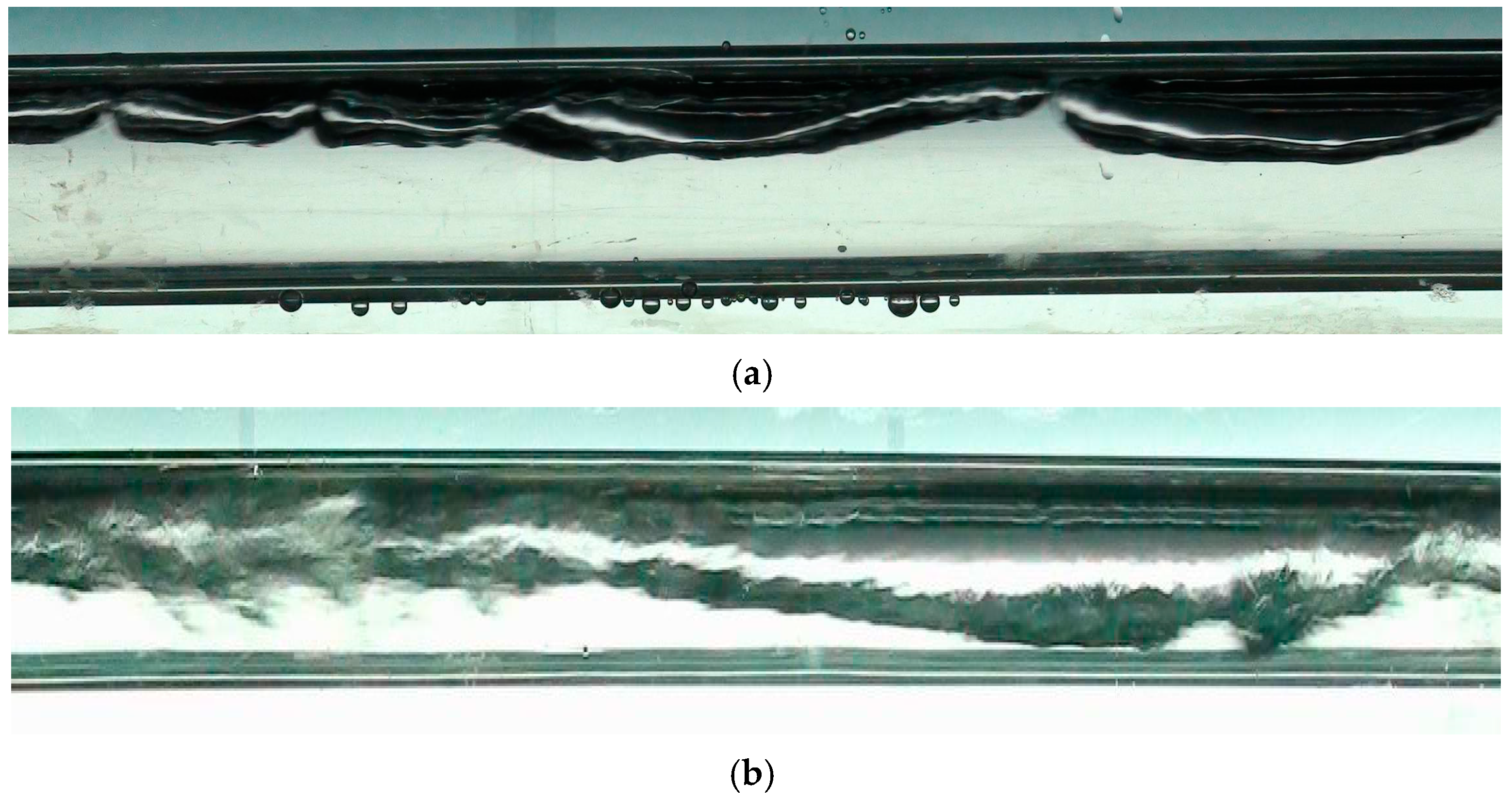
3.1.2. Spiral Wave Stratified Flow
This flow pattern was observed under conditions where the liquid-phase velocity was relatively low, while the gas-phase velocity was significantly high. Additionally, it was also noted at the terminus of the experimental tube when both the liquid-phase and gas-phase velocities were high. The defining characteristic of the spiral wave stratified flow is the layering between the liquid and gas phases, as shown in
Figure 4.
For example, spiral wave stratified flow was observed under the following conditions: using the 2# spiral vane, with an SDS solution concentration of 10 mg/kg, a liquid-phase velocity of 0.5 m/s, and a gas-phase velocity of 0.5 m/s. Alternatively, it was also observed with the 4# spiral vane, an SDS solution concentration of 30 mg/kg, a liquid-phase velocity of 0.5 m/s, and a gas-phase velocity of 1.0 m/s.
Figure 4.
Spiral wave stratified flow. (a) (Spiral vane was 2#, the concentration of SDS solution was 10 mg/kg, the velocity of liquid phase was 0.5 m/s, the velocity of gas phase was 0.5 m/s). (b) (Spiral vane was 4#, the concentration of SDS solution was 30 mg/kg, the velocity of liquid phase was 0.5 m/s, the velocity of gas phase was 1.0 m/s).
3.1.3. Spiral Axial Flow
This flow pattern was observed under conditions where the liquid-phase velocity was high, while the gas-phase velocity remained comparatively low. As the gas-phase flow rate increased, this flow pattern transitioned into spiral linear flow, as illustrated in
Figure 5.
For example, spiral axial flow was observed under the following conditions: using the 5# spiral vane, with an SDS solution concentration of 90 mg/kg, a liquid-phase velocity of 2.5 m/s, and a gas-phase velocity of 0.5 m/s. Alternatively, it was also noted with the 8# spiral vane, an SDS solution concentration of 70 mg/kg, a liquid-phase velocity of 2.0 m/s, and a gas-phase velocity of 0.5 m/s.
Figure 5.
Spiral axial flow. (a) (Spiral vane was 5#, the concentration of SDS solution was 90 mg/kg, the velocity of liquid phase was 2.5 m/s, the velocity of gas phase was 0.5 m/s). (b) (Spiral vane was 8#, the concentration of SDS solution was 70 mg/kg, the velocity of liquid phase was 2.0 m/s, the velocity of gas phase was 0.5 m/s).
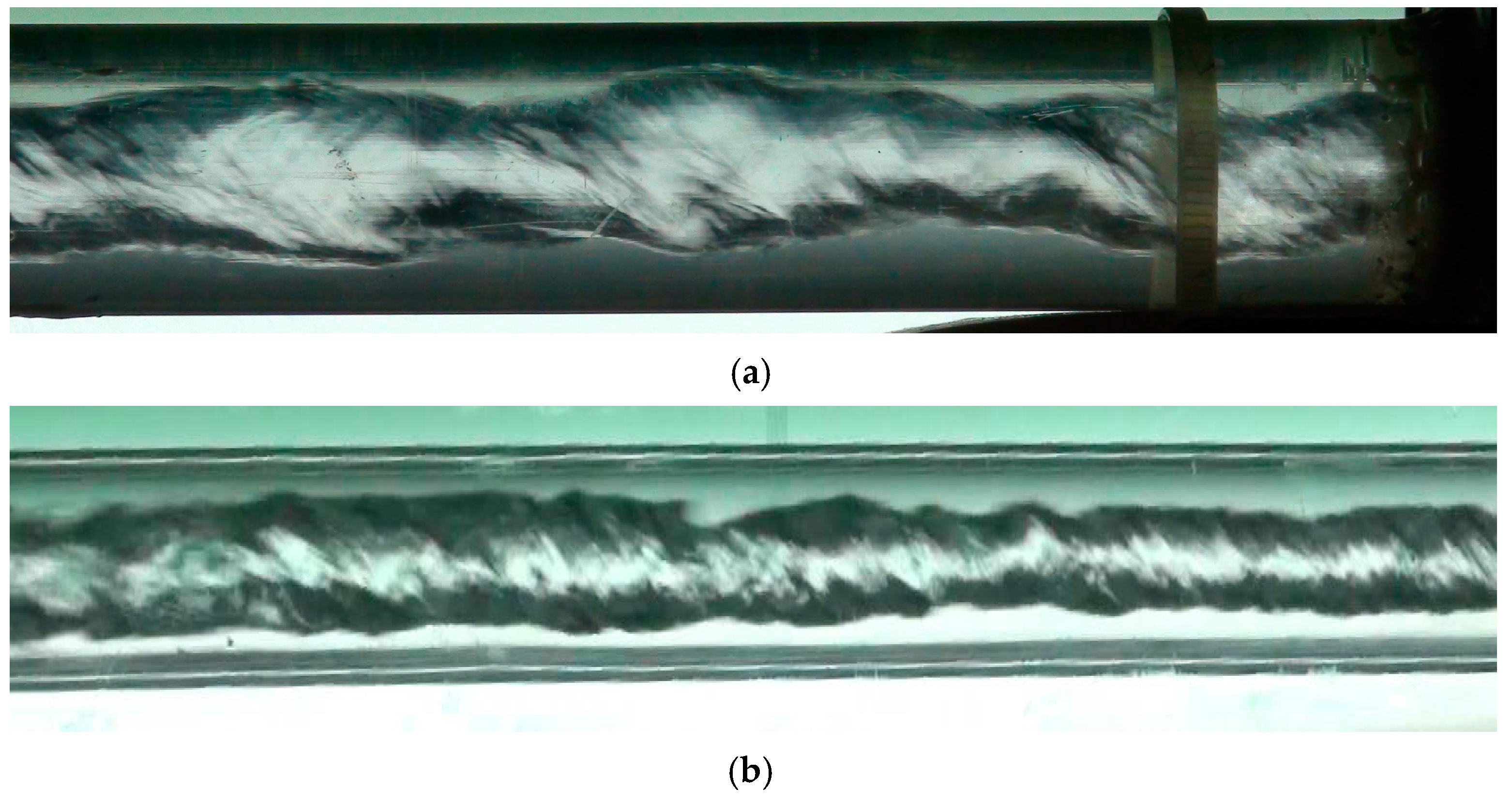
3.1.4. Spiral Dispersed Flow
This flow pattern was observed under conditions where both the liquid-phase and gas-phase velocities were high, as illustrated in
Figure 6. For example, spiral dispersed flow was expected to occur under the following conditions: using the 6# spiral vane, with an SDS solution concentration of 50 mg/kg, a liquid-phase velocity of 2.0 m/s, and a gas-phase velocity of 2.5 m/s. Alternatively, it was also observed with the 8# spiral vane, an SDS solution concentration of 50 mg/kg, a liquid-phase velocity of 1.0 m/s, and a gas-phase velocity of 1.0 m/s.
Figure 6.
Spiral dispersed flow. (a) (Spiral vane was 6#, the concentration of SDS solution was 50 mg/kg, the velocity of liquid phase was 2.0 m/s, the velocity of gas phase was 2.5 m/s). (b) (Spiral vane was 8#, the concentration of SDS solution was 50 mg/kg, the velocity of liquid phase was 1.0 m/s, the velocity of gas phase was 1.0 m/s).
3.1.5. Flow Pattern Map
The transition of flow patterns in gas-liquid two-phase spiral pipeline flow can be effectively represented through a flow pattern map. A series of experiments were conducted to investigate gas-liquid two-phase spiral pipeline flow with a low concentration of SDS solution. All flow patterns were meticulously documented using a Sony HDR-XR550E high-definition hard disk camera.
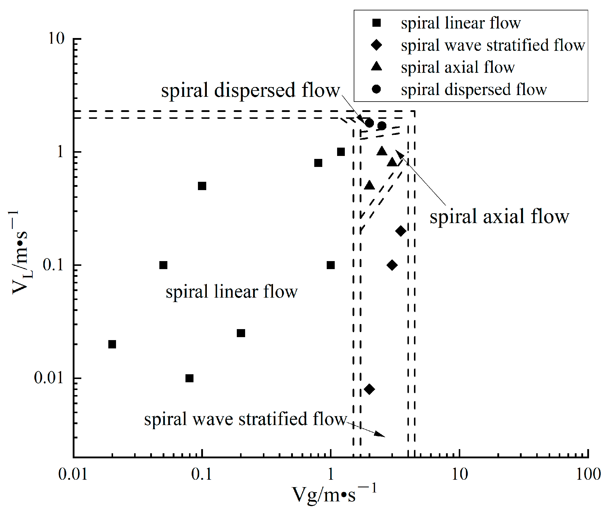
Based on the experimental data, the flow pattern map for gas-liquid two-phase spiral pipeline flow with a low concentration of SDS solution in a horizontal tube (23 mm in diameter, constructed from organic glass) has been presented, as shown in
Figure 7. The double dashed line delineates the boundaries of distinct flow patterns, while the area between the two dashed lines represents the transition zone for flow pattern transformation.
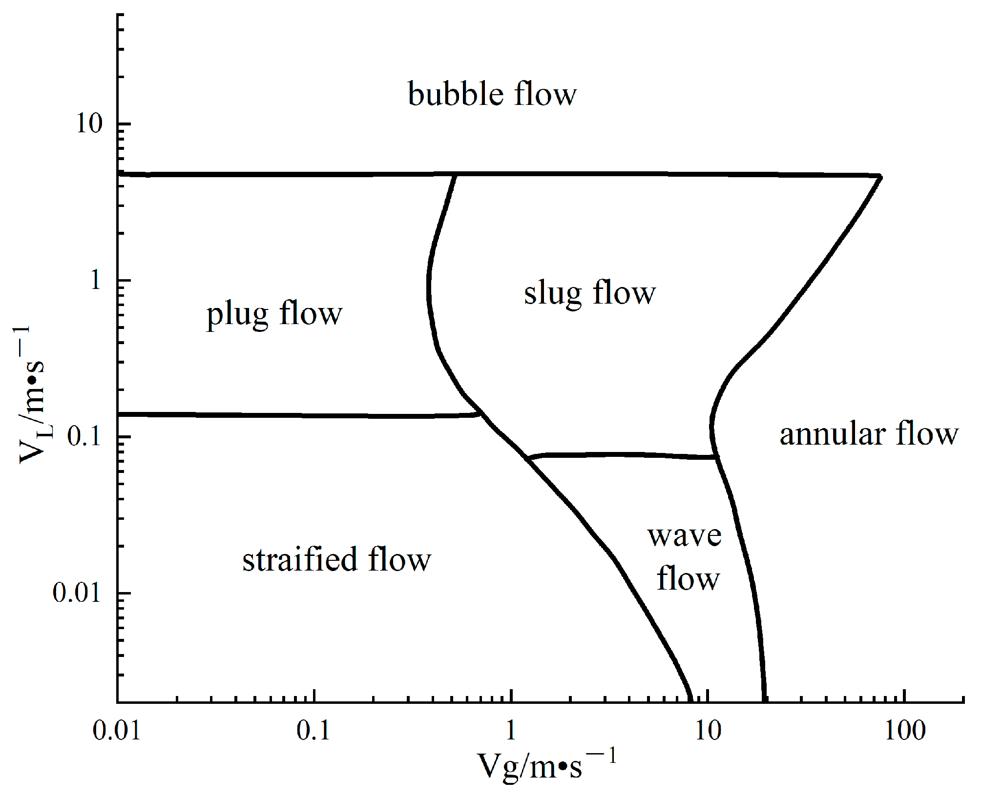
Additionally, the flow pattern map has been compared with the classical Mandhane flow pattern map for gas-liquid two-phase flow in a horizontal pipeline [
23], as illustrated in
Figure 8. In the context of gas-liquid two-phase spiral pipeline flow with a low concentration of SDS solution, four distinct flow patterns were identified: spiral linear flow, spiral wave stratified flow, spiral axial flow, and spiral dispersed flow.
In comparison to the classical Mandhane flow pattern map, three novel flow patterns were observed: spiral linear flow, spiral axial flow, and spiral dispersed flow. In the classical Mandhane flow pattern map, stratified flow does not appear until the liquid-phase velocity is very low. However, under the condition where the liquid-phase velocity exceeds 2.0 m/s, stratified flow still occurs in gas-liquid two-phase spiral pipeline flow with a low concentration of SDS solution. Spiral linear flow was found to be the most common flow pattern and it transitions into spiral axial flow with increasing gas-phase velocity. Furthermore, spiral dispersed flow was only observed when both the liquid-phase and gas-phase velocities were high for gas-liquid two-phase spiral pipeline flow with a low concentration of SDS solution.
3.2. Influence of Velocities
The velocities of the gas and liquid phases are critical factors that govern the behavior and characteristics of gas-liquid two-phase spiral pipeline flows. Experimental results show that changes in the liquid-phase and gas-phase velocities significantly influence flow patterns, spiral geometry, and mixing efficiency. Understanding these effects is essential for optimizing pipeline design and operation, particularly in systems where enhanced mixing and minimized pressure drops are desired.
The liquid-phase velocity directly affects the degree of attenuation in spiral flow patterns. At low liquid velocities, flow attenuation is pronounced, leading to shorter spiral flow paths and weaker phase mixing, as shown in
Figure 3 and
Figure 4a. As the liquid velocity increases, the attenuation decreases, allowing the flow patterns to remain more robust and continuous, as shown in
Figure 5a and
Figure 6a. This effect is attributed to the higher momentum of the liquid phase, which counteracts the inertial forces responsible for flow attenuation. Another notable observation is the influence of liquid-phase velocity on spiral geometry. As liquid velocity increases, the pitch of the spiral flow becomes larger, as shown in
Figure 3 and
Figure 5b, resulting in a more extended helical trajectory. Concurrently, the spiral diameter decreases, indicating that the flow becomes more compact and tightly wound. These geometric changes suggest that higher liquid velocities enhance the axial velocity component relative to the tangential velocity, favoring more efficient transport of phases along the pipeline. The increase in liquid velocity also promotes transitions from stratified or wave-stratified flow to more dispersed flow patterns. This is because higher liquid velocities increase turbulence levels, breaking down large-scale interfaces and encouraging finer dispersion of the gas phase within the liquid. Such transitions are advantageous in industrial processes requiring uniform gas-liquid mixing, such as natural gas hydrate formation or chemical reaction engineering.
The gas-phase velocity plays an equally important role in shaping flow patterns. At low gas velocities, stratified or wave-stratified flow patterns dominate, characterized by distinct layering of gas and liquid phases, as shown in
Figure 3 and
Figure 4a. These flow patterns are typically observed under conditions where the gas velocity is insufficient to generate significant turbulence or disrupt the liquid surface. As gas velocity increases, the flow transitions into more dynamic regimes, such as dispersed flow, as shown in
Figure 4a,b and
Figure 6a. This transition is driven by the increased momentum of the gas phase, which interacts with the liquid phase to create finer bubbles and enhance phase mixing. High gas velocities also contribute to greater energy dissipation and turbulence within the flow, further stabilizing dispersed flow patterns. However, excessive gas velocities can introduce instabilities, such as the formation of slugs or waves, as shown in
Figure 5a, depending on the specific pipeline geometry and operating conditions.
In general, the interplay between gas and liquid velocities is crucial in determining flow pattern transitions and stability. For instance, when both velocities are low, stratified or linear flow patterns are observed, marked by weak interactions between phases, as shown in
Figure 3 and
Figure 4a,b. As either velocity increases, transitions to wave-stratified or dispersed flow occur, reflecting enhanced interphase interaction and mixing, as shown in
Figure 5a and
Figure 6a. The combined effect of high liquid and gas velocities typically results in the most efficient mixing and stable flow patterns, such as dispersed flow, where the phases are uniformly distributed throughout the pipeline.
3.3. Influence of Angles and Area
The geometry of the spiral vanes, characterized by their angle and area, exerts a significant influence on the flow patterns observed in gas-liquid two-phase spiral pipeline flows containing a low concentration of sodium dodecyl sulfate (SDS) solution. The experiments revealed that variations in these geometric parameters lead to notable changes in the behavior and transitions of the flow patterns, with specific tendencies observed under controlled conditions.
The spiral angle of the vane plays a critical role in determining the ease of transition between different flow patterns. As the angle increases, the flow patterns tend to transition more readily into spiral dispersed flow, as shown in
Figure 5a and
Figure 6a. This effect is particularly pronounced under conditions where the gas-phase velocity is held constant. Larger spiral angles introduce higher turbulence levels and stronger interactions between the gas and liquid phases, which facilitates the breakdown of stratified flow patterns and promotes finer mixing. In contrast, under the same constant gas-phase velocity, smaller spiral angles favor the development of spiral linear flow, as shown in
Figure 4b and
Figure 6b. This behavior suggests that the angle of the vane modulates the tangential and axial velocities of the flow, influencing the distribution of forces within the pipeline and, consequently, the resulting flow pattern.
The area of the spiral vane also has a pronounced impact on the observed flow patterns. A larger vane area, defined as the percentage of a single blade’s surface area relative to the total vane area, promotes the transition to spiral dispersed flow, as shown in
Figure 4b and
Figure 6b. The increased vane area provides a larger surface for phase interaction, enhancing the momentum exchange between the gas and liquid phases. Conversely, when the vane area decreases, the flow patterns tend to favor spiral linear flow, as shown in
Figure 3 and
Figure 5a,b. This relationship is consistent across various experimental conditions and highlights the importance of vane area in dictating flow stability and the degree of phase mixing.
The angle and area of the spiral vanes are key parameters that influence the flow patterns in gas-liquid two-phase spiral pipeline flows with low concentrations of SDS. Larger angles and areas promote spiral dispersed flow, while smaller values favor spiral linear flow. These findings provide valuable insights for the design of spiral vane systems to optimize multiphase flow behavior in industrial pipelines.
3.4. Influence of Surfactant Solution
The addition of low-concentration sodium dodecyl sulfate (SDS) solution had a profound impact on the gas-liquid two-phase spiral flow within horizontal pipelines. The surfactant primarily influences the system by reducing the surface tension between the gas and liquid phases, which is critical in determining the flow characteristics. At low concentrations (10–90 mg/kg), SDS effectively lowers surface tension, enabling the formation of flow patterns that are distinct from those observed in systems without surfactants. This reduction in surface tension enhances the solubility of gas within the liquid phase and promotes more uniform mixing, leading to flow patterns that are better suited for industrial applications, such as natural gas hydrate transportation and chemical process intensification.
A notable observation from the experiments is the facilitation of spiral dispersed flow under conditions where surfactants are present. This flow pattern, which is characterized by a fine dispersion of gas bubbles within the liquid phase, occurs more readily with SDS than in its absence. The underlying mechanism involves a reduction in cohesive forces at the interface, which suppresses gravitational effects that typically promote stratification. Instead, the surfactant introduces greater uniformity to the gas-liquid distribution by minimizing wave formation and stabilizing dispersed flow patterns; this conclusion can be found in comparison with [
4,
7]. This is particularly advantageous for applications requiring efficient gas-liquid interaction, as dispersed flow maximizes the interfacial area and enhances mass transfer.
The role of SDS in altering flow patterns can also be understood through its effect on critical parameters like capillary forces and Weber number. A lower surface tension corresponds to a higher Weber number, which indicates a reduced dominance of surface tension forces relative to inertial forces. This shift facilitates transitions away from stratified and slug flow patterns to dispersed flow, where turbulence dominates. Such behavior aligns with findings from previous studies, including Hanratty et al. (1961), who reported that surfactants mitigate wave formation in two-phase flows, and Spedding et al. (2008), who demonstrated the suppression of gravitational waves in horizontal pipes.
The impact of SDS on spiral flow patterns also extends to energy considerations. The suppression of high-energy transitions, such as slugging, can lead to more stable flow patterns and lower pressure fluctuations. This stability reduces operational risks, particularly in high-pressure environments like natural gas pipelines. Furthermore, dispersed flow, facilitated by SDS, offers a lower pressure drop gradient compared to wave-stratified flow, as shown in
Figure 4b and
Figure 6b, translating into energy savings for long-distance fluid transport.
Experimentally, the presence of SDS influenced the transition boundaries of flow patterns significantly. For instance, at liquid-phase velocities of 1.0–2.5 m/s and gas-phase velocities of 1.5–3.0 m/s, dispersed flow was observed predominantly in systems with SDS, as shown in
Figure 6a,b. In contrast, systems without SDS exhibited stratified or slug flows under similar conditions. The findings suggest that even low concentrations of SDS are sufficient to shift flow behavior towards regimes that are desirable for engineering applications.
Another crucial aspect is the enhanced stability of dispersed flow patterns due to SDS. By lowering the surface tension, the surfactant reduces the tendency for bubble coalescence, resulting in smaller, more evenly distributed gas bubbles, as shown in
Figure 3 and
Figure 4a. This stabilization is critical in processes like natural gas hydrate formation, where the contact area between gas and liquid phases directly influences the efficiency of hydrate crystallization.
3.5. Influence of Pressure Drop
The pressure drop in gas-liquid two-phase spiral pipeline flows with a low concentration of sodium dodecyl sulfate (SDS) solution is strongly influenced by the observed flow patterns. Experimental results provide detailed insights into the relationship between flow patterns, void fractions, and pressure drops, highlighting the conditions under which pressure gradients vary. The gas-liquid two-phase spiral pipe flow pressure drop data are shown in
Table 3. Spiral linear flow is SLF, spiral dispersed flow is SDF, spiral axial flow is SAF, and spiral wave stratified flow is SWAF.
In the experiments, it was noted that at a constant volume void fraction, the pressure drop is highly dependent on the specific flow pattern. Among the flow patterns observed, spiral wave stratified flow exhibited the maximum pressure drop, while spiral dispersed flow demonstrated the minimum pressure drop, as shown in
Table 3. This indicates that flow patterns with greater stratification or wave formation introduce higher resistance to flow, which translates into increased energy losses. The gradient of pressure drop was also found to vary significantly among the flow patterns. Spiral dispersed flow, characterized by uniform phase distribution and enhanced mixing, consistently showed the lowest pressure drop gradient compared to other patterns. This finding emphasizes the role of homogeneous phase interactions in reducing the overall resistance encountered by the fluid flow.
The volume void fraction, representing the proportion of the gas phase within the pipeline, plays a critical role in determining the magnitude of the pressure drop. As the volume void fraction increases, the pressure drop for gas-liquid two-phase spiral flows also increases. This trend is consistent across all observed flow patterns. The increase in void fraction amplifies the interaction forces between the gas and liquid phases, particularly in flow patterns such as wave stratified flow, as shown in
Figure 4a,b. These interactions lead to greater energy dissipation, thereby elevating the pressure drop. However, in the case of spiral dispersed flow, the impact of void fraction on pressure drop is less pronounced due to the efficient mixing and minimized wave formation inherent to this flow pattern.
Spiral dispersed flow stands out as the most efficient flow pattern in terms of pressure drop characteristics. The uniform dispersion of gas within the liquid phase minimizes the development of large-scale interface disturbances, such as waves or slugs, which are common in other flow patterns. This results in a more stable and lower pressure drop system. Additionally, the reduced pressure drop gradient in spiral dispersed flow is a direct consequence of the homogenized distribution of phases, which lowers the overall frictional resistance in the pipeline.
On the other hand, spiral wave stratified flow exhibited the highest pressure drop among all patterns, as shown in
Table 3. This can be attributed to the distinct layering of gas and liquid phases, which creates significant interfacial shear and turbulence. Furthermore, the wave structures that develop at the interface introduce additional resistance, compounding the energy losses in this flow pattern.
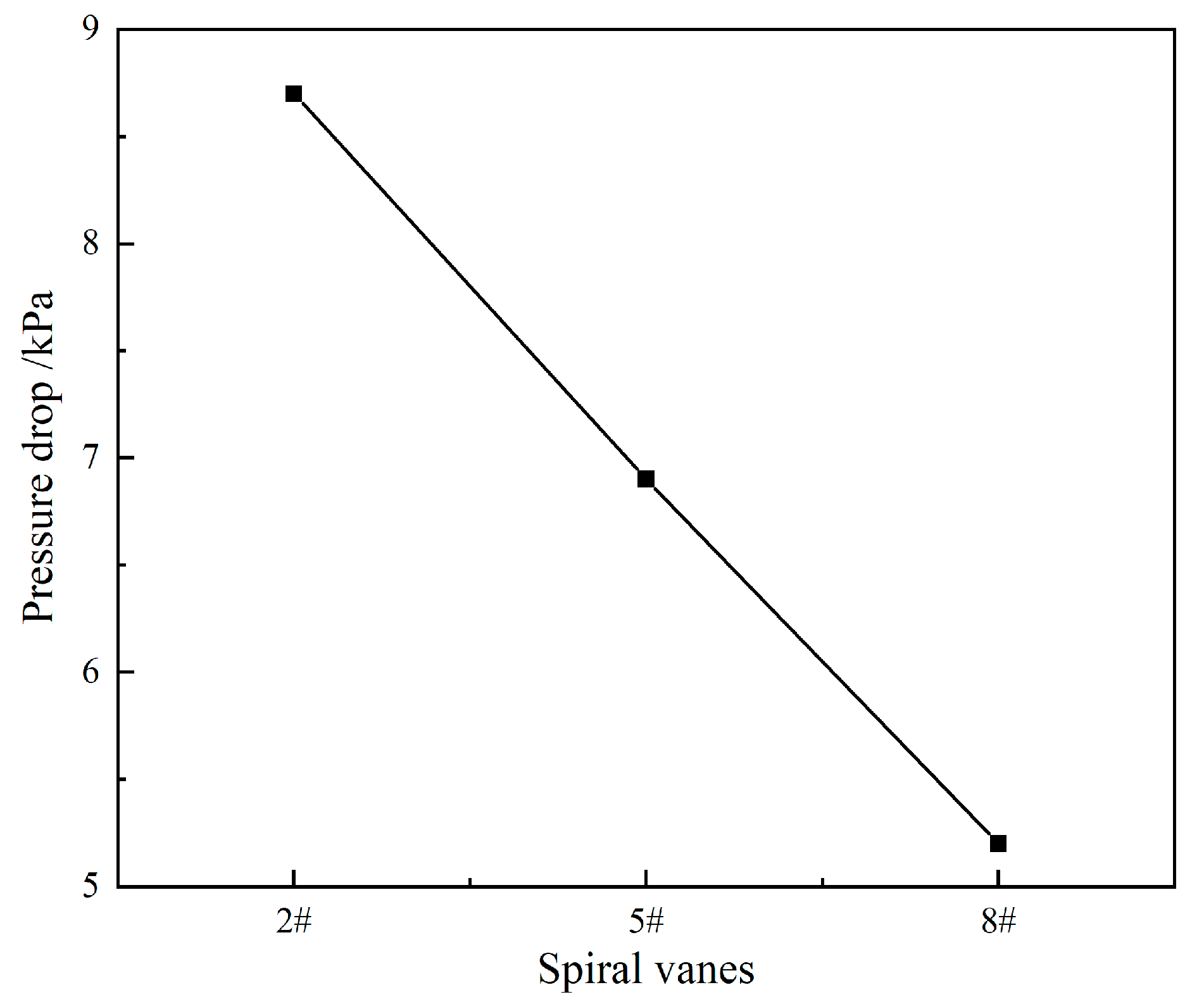
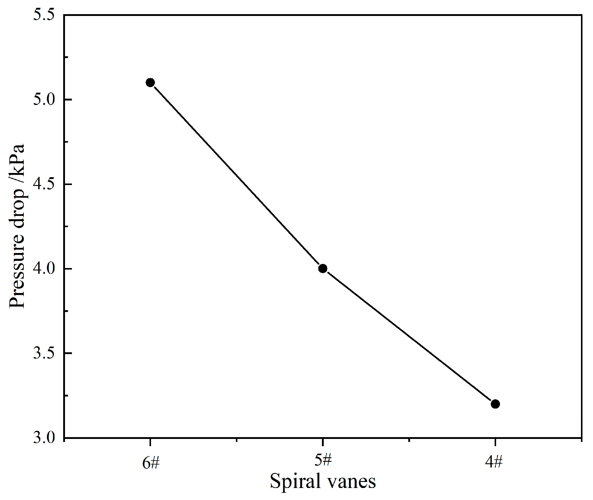
The influence of impeller parameters on pressure drop is shown in
Figure 9 and
Figure 10. As the vane size decreases, the pressure drop decreases gradually. When the vane size gradually decreases, it is equivalent to the increase of the gas-liquid two-phase flow area, which makes it easier for the gas-liquid two phases to pass through the impeller and enter the pipe section, and the spiral strength is weakened, thus reducing the friction on the pipe wall and reducing the pressure drop. The pressure drop increases gradually with the increase of spiral angle. The change of spiral angle mainly affects the flow direction. When the spiral angle increases, the gas-liquid phase will have a larger tangential velocity after passing through the vane, which will increase the friction on the tube wall and increase the pressure drop.
The findings from this study underscore the importance of selecting the appropriate flow pattern for minimizing pressure drops in industrial pipeline systems. Spiral dispersed flow offers a clear advantage in reducing energy consumption, making it suitable for applications where long-distance transportation or high flow efficiency is required. In contrast, the high-pressure drop associated with spiral wave stratified flow necessitates careful management to avoid excessive energy losses and operational inefficiencies.
Our experiments reveal that the pressure drop in gas-liquid two-phase spiral pipeline flows is primarily governed by the interplay between flow patterns and void fractions. Spiral dispersed flow, characterized by efficient phase mixing and low turbulence, consistently minimizes pressure drop and gradient, while spiral wave stratified flow introduces the greatest resistance due to its inherent interfacial dynamics. These insights provide a valuable foundation for optimizing pipeline designs and operating conditions to achieve desired flow and pressure characteristics in various industrial applications.
4. Conclusions
This study investigated the flow characteristics of gas-liquid two-phase spiral flows in horizontal pipelines under the influence of low concentrations of sodium dodecyl sulfate (SDS) surfactant solutions. Four distinct flow patterns were identified: spiral linear flow, spiral wave stratified flow, spiral axial flow, and spiral dispersed flow. Unlike gas-liquid two-phase spiral flows without surfactants, where spiral bubbly flow and spiral slug flow are commonly observed, these patterns were absent when SDS was present, even at low concentrations.
The experiments revealed that the addition of SDS significantly altered flow behavior by reducing surface tension between the gas and liquid phases. This reduction facilitated greater gas solubility in the liquid phase and enhanced the mixing between phases, resulting in the frequent occurrence of spiral dispersed flow. This pattern is particularly advantageous for industrial applications as it improves phase homogeneity and minimizes pressure drop.
The effects of liquid-phase velocity were found to be critical. As liquid velocity increased, the attenuation of flow patterns weakened, the spiral diameter decreased, and the pitch of the spiral flow enlarged. These findings suggest that increasing liquid-phase velocity stabilizes flow patterns and promotes a more efficient flow pattern, which is beneficial for processes that require robust and sustained mixing.
The geometry of spiral vanes, specifically their angle and surface area, played a pivotal role in influencing flow transitions. Larger spiral angles facilitated the transition to dispersed flow, while smaller angles encouraged spiral linear flow. Similarly, larger vane areas promoted dispersed flow patterns by enhancing gas-liquid interaction, whereas smaller areas favored linear flow. These findings highlight the importance of geometric optimization in designing pipeline systems for specific applications.
Pressure drop characteristics were heavily influenced by flow patterns. Spiral wave stratified flow exhibited the highest pressure drop due to interfacial shear and wave formation, while spiral dispersed flow demonstrated the lowest pressure drop, attributed to its uniform phase distribution and reduced turbulence. These findings emphasize the need for careful selection of flow patterns to minimize energy consumption and optimize pipeline performance.
The study provides a comprehensive understanding of how surfactants, flow velocities, and spiral vane geometry influence gas-liquid two-phase spiral flows. These insights contribute to the development of efficient pipeline systems for industrial applications such as natural gas hydrate formation, transportation, and multiphase flow management. The experimental observations and findings lay a foundation for further studies on optimizing flow conditions and expanding the applicability of gas-liquid spiral flow systems in various energy and process industries.


