Article

Exploring Post-Machining Alternatives Under Dry Conditions for Thin-Walled Additive Manufacturing Components Aided by Infrared Thermography

1
Eurecat, Centre Tecnològic de Catalunya, Unit of Metallic and Ceramic Materials, Plaça de la Ciència, 2, 08243 Manresa, Spain
2
CIEFMA, Center for Research in Structural Integrity, Reliability and Micromechanics of Materials, Department of Materials Science and Engineering, Universitat Politècnica de Catalunya, Campus Diagonal Besòs-EEBE, 08019 Barcelona, Spain
3
GSC, Grupo Sevilla Control or Sevilla Control Group, C/Manganeso, 2–P.I. Calonge–Sevilla, 41007 Sevilla, Spain
*
Authors to whom correspondence should be addressed.
Processes 2025, 13(3), 717; https://doi.org/10.3390/pr13030717
Submission received: 24 January 2025 / Revised: 25 February 2025 / Accepted: 27 February 2025 / Published: 1 March 2025

Abstract

:
Additive manufacturing (AM) techniques have transformed the production of parts and components with intricate geometries and customized designs, driving innovation in sustainable manufacturing practices. The additive manufacturing technology used in this work was selective laser melting (SLM), a process that uses laser energy to sinter powdered metals into solid structures. Among the various materials utilized in AM, Ti6Al4V titanium alloys are of particular interest due to their favorable mechanical properties, corrosion resistance, biocompatibility, and potential for reducing material waste. However, the machining of additively manufactured titanium parts presents challenges due to the material’s low conductivity, elastic modulus, and chemical affinity with cutting tools, which impact tool wear and surface finish quality. Milling, a commonly employed process for finishing titanium parts, often involves significant energy use and tool wear, highlighting the need for optimized and eco-conscious machining strategies. This study aims to establish correlations among four key aspects: (1) surface finish of machined Ti6Al4V AM parts, (2) cutting tool damage, (3) dry milling parameters including different cutting tools, and (4) variation of temperature at the contact surface of AM parts and tools using infrared thermography. By examining parameters such as feed per tooth (Fz), axial depth of cut (Ap), spindle trajectories (trochoidal, helicoidal, and linear), and cutting tool diameters, this work identifies conditions that enhance process efficiency while reducing environmental impact. Infrared thermography provides insights into temperature variations during milling, correlating these changes to surface roughness and critical machining parameters, thus contributing to the development of sustainable and high-performance manufacturing practices.

Graphical Abstract

1. Introduction

Ti-6Al-4V alloy and its variations are extensively utilized in industrial applications, including aerospace, biomedical, and energy sectors, due to their exceptional performance characteristics. These attributes include excellent corrosion resistance, a high strength-to-weight ratio, superior strength retention at elevated temperatures, and outstanding biological compatibility [1]. Additionally, its high potential for material efficiency and waste reduction makes Ti-6Al-4V an attractive material in industries striving to meet sustainability goals. As a result, the demand for Ti-6Al-4V has significantly increased in sectors like aerospace, where weight savings and efficiency are paramount [2].
Additive manufacturing (AM) has emerged as a transformative technology in these sectors, particularly due to its ability to fabricate thin-walled and complex-shaped components with near-net-shape features. This capability significantly reduces material waste, making AM a viable solution for manufacturing high-performance materials such as titanium alloys while minimizing environmental impact and production costs [3,4]. However, AM components often present poor surface quality, which is a critical concern for parts subjected to complex loading conditions, including contact fatigue and sliding wear. In such cases, post-machining operations are essential but become particularly challenging when processing thin-walled surfaces [5].
Milling is a widely used post-machining method for processing thin-walled additive manufacturing (AM) parts. However, when components are made from materials classified as “difficult-to-cut”, the cutting process becomes more complex. Titanium alloys, such as Ti-6Al-4V, fall into this category due to their high chemical reactivity and poor thermal conductivity [1,6,7]. Additionally, their low modulus of elasticity results in complex and atypical deformation mechanisms under extreme working conditions, including pronounced thermal softening at elevated temperatures. This distinguishes titanium alloys from conventional metals like steel and aluminum.
These challenges not only hinder productivity but also lead to energy inefficiencies and greater environmental burdens in traditional manufacturing processes. Moreover, the machining of titanium generates significant heat, accelerating tool wear and reducing operational efficiency. This limits production rates and negatively impacts the surface quality of the finished parts. While these phenomena have been extensively studied in the context of milling Ti-6Al-4V blocks (both cast and forged), some of these limitations can be mitigated by incorporating various lubricants into the process [8].
However, the use of lubricants introduces its own set of challenges, such as higher production costs, the contamination of scrap material with metal chips and cutting fluids, and adverse environmental and health effects. Workers may be exposed to harmful aerosols created during the evaporation of lubricants, raising significant health concerns and highlighting the need for more sustainable approaches [9,10,11]. In response, efforts have been made to develop more environmentally friendly lubricants based on organic oils [9]. Despite these advancements, the most effective solution may lie in minimizing or eliminating the use of lubricants entirely through the adoption of dry machining techniques.
Beyond lubrication, machining AM thin-walled Ti-6Al-4V components for the aerospace industry introduces additional challenges, such as vibrations (chattering) and significant displacements of both the cutter and the workpiece. Milling thin-walled structures is a dynamically unstable process due to cutting and clamping forces acting during chip removal. This phenomenon results in wall deflections, leading to undesirable vibrations that further compromise machining accuracy and surface quality. These issues are exacerbated by the lower stiffness of AM thin-walled structures compared to their bulk counterparts, making dynamic instability a critical factor to consider [12]. For this reason, this study proposes three different spindle trajectories and two cutting tool diameters to investigate the best options for minimizing vibrations and enhancing surface quality.
Finally, it must be noted that these factors do not only affect the efficiency of the machining process itself but also the performance of the finished products. For instance, the role of surface roughness as a limiting factor of fatigue performance is well known and reported in the literature, even with studies on the specific case of additive-manufactured Ti-6Al-4V [13]. On the other hand, the role of surface finish is more nuanced in medical applications [14]; nevertheless, obtaining a well-controlled and repeatable surface quality is paramount, for instance, to ensure osteointegration in implants.
Given these challenges, this study aims to explore different cutting conditions to reduce heat generation during the milling of thin-walled Ti-6Al-4V components produced via selective laser melting (SLM) [15]. The evaluation will be conducted in terms of tool wear and surface quality of the machined AM component. To accomplish this, infrared thermography is used to correlate heat generation during the milling process with temperature variations and the resulting surface roughness. Previous studies have successfully applied infrared thermography in machining research on materials such as steel, aluminum, and titanium [16,17,18,19]. The key advantages of thermographic devices are their non-contact nature and rapid response, allowing measurements in areas where chips could damage the measurement system or in otherwise inaccessible locations. Since no thermocouple needs to be attached to the tool or sample, infrared measurement does not negatively impact industrial processes, making it a reliable technique for monitoring temperature in dry machining operations.
Moreover, this study examines the correlation among four critical aspects: (1) finishing surface quality of machined Ti-6Al-4V AM parts, (2) cutting tool damage, (3) dry milling parameters—including different cutting tools—and (4) temperature variation at the contact surface of the tool and AM part. The milling parameters investigated include feed per tooth (Fz), axial depth of cut (Ap), three spindle trajectories (trochoidal, helicoidal, and linear), and two cutting tool diameters. By focusing on dry machining techniques and their environmental implications, this work contributes to the development of sustainable manufacturing practices [8], and the removal of the lubricant has a positive economic impact, as seen with the most recent 90’s versions [20].

2. Materials and Methods

2.1. Materials and Specimens

All samples were obtained using 3D additive manufacturing of Ti-6Al-4V powder. Specifically, the technology employed was Selective Laser Melting (SLM), an advanced version of the Selective Laser Sintering (SLS) process. In SLM, a high-power laser melts the metal alloy powders on the powder bed to form dense, predefined metal objects. The SLM parameters used to produce the samples included a laser power of 200 W, a scanning velocity of 1500 mm/s, a slice thickness of 30 μm, and a hatch distance of 60 μm. Finally, the samples were heat treated by annealing at 850 °C for 2 h.
The chemical composition of the Ti-6Al-4V powder for SLM and its comparison with bulk material specifications are presented in Table 1.
The dry milling process was performed on an SLM component, as shown in Figure 1. The component consisted of a platform measuring 70 mm × 48 mm with a thin-wall support of 2.8 mm thickness, attached to a base measuring 64 mm × 64 mm with a thickness of 32 mm.

2.2. Test Methodology

2.2.1. Initial Setup Trials

Initial tests were conducted with the SLM component rigidly fixed in an industrial vise. This setup effectively prevented vibrations caused by the thin-wall support geometry. By ensuring stable clamping, the focus was placed on analyzing cutting tool damage and its correlation with temperature changes, as well as determining the optimal spindle trajectory among trochoidal, helical, and linear paths.
Once the optimal trajectory was determined, the next step was to perform tests on the component without the rigid vise, observing the behavior of the thin-walled support and its inherent geometry, as well as its effects on temperature variations and the surface roughness of the finished part.
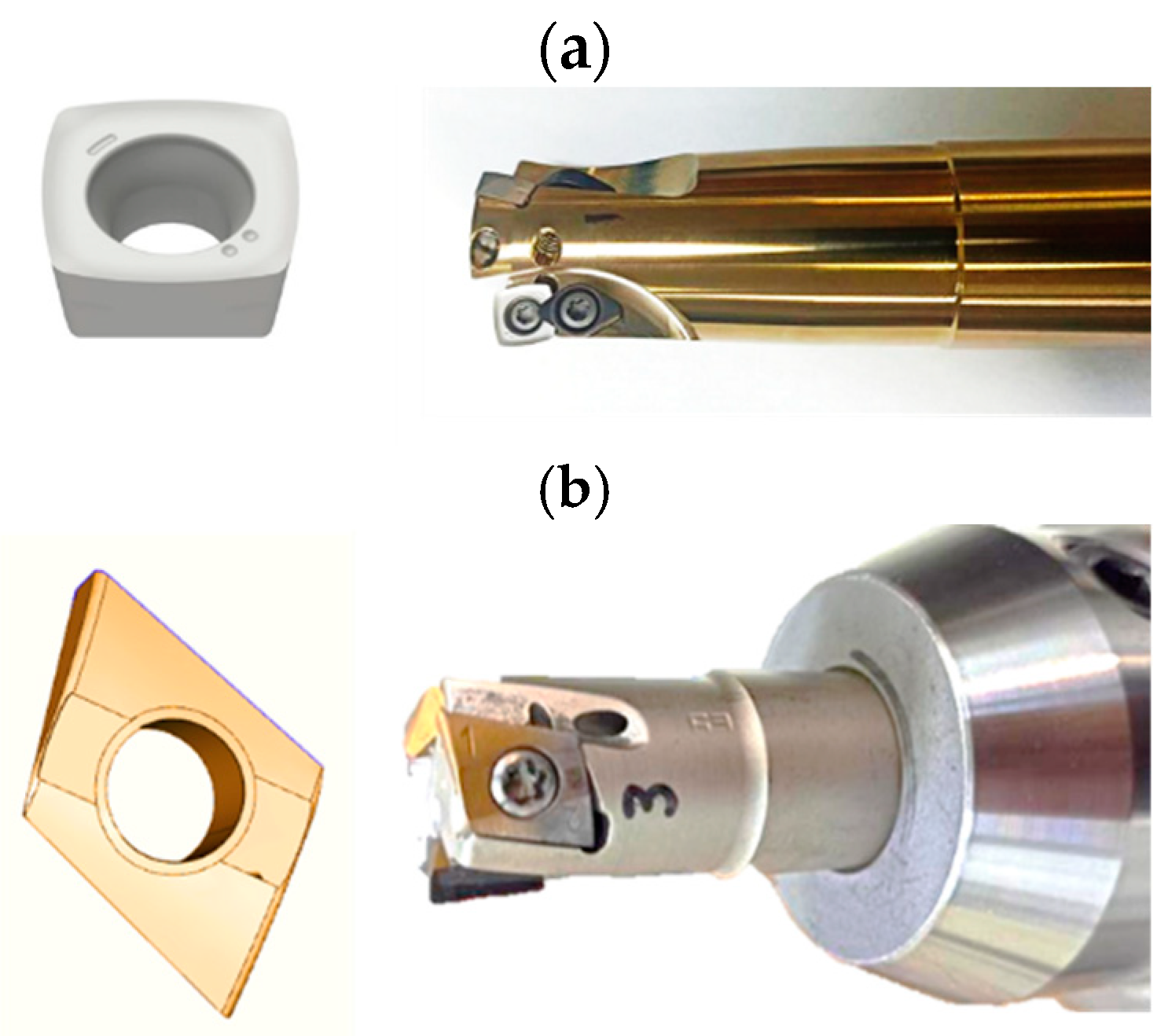
All tests were performed using a CNC machining center, the five-axis HAAS UMC-750. Initial trials to determine the best trajectory (trochoidal, helical, and linear) examined milling parameters such as feed per tooth (Fz) and axial depth of cut (Ap). The cutting tool used in these tests was the XDLX 09T308ER-F40 CTC5240, paired with the holder tool GA SD090 C 032 Z3, which had a diameter of 32 mm. This configuration was referred to as Setup 1 (see Figure 2a). Figure 3 illustrates a schematic of the three different trajectories used in the initial trials. The linear trajectory was performed with a total of four milling passes for each component to machine the entire surface. Table 2 presents the variation in feed per tooth (Fz) and axial depth of cut (Ap) for each sample. The fixed milling parameters for all these tests were cutting velocity (Vc) at 60 m/min, radial cutting depth (Ae) at 80%, feed rate (Vf) at 229 mm/min, spindle speed (n) at 764 rpm, and number of effective edges (Zc) at 3. The parameters selected for this study are based on a substantial amount of the literature and references related to titanium machining. A summary can be found in [21], while more specific references for dry conditions, similar 3D printing techniques, and the milling process are provided in [22,23,24]. Taking into account the reference data, as well as the specifications of our tools and system, the milling parameters and their variations were defined.
New-edge tools were used for all tests under a dry cutting environment to eliminate the influence of tool wear on cutting temperature and surface roughness. This ensured a reliable correlation among the samples machined under different test conditions.

2.2.2. Setup Variations

Once the optimal parameters and trajectory were identified, a different set of cutting tools and holder was used. The second cutting tool was a T290 LNMT 100405TR IC808 with two cutting edges and a grade IC808, offering a submicron substrate with excellent chipping resistance, combined with a “SUMO TEC” PVD coating of TiAlN/AlTiN+TiN. The corresponding holder was the T290 ELN D20-03-W20-10, with a diameter of 20 mm. This configuration was referred to as Setup 2 (see Figure 2b). The tests conducted with this cutting tool and holder utilized a trochoidal trajectory. In these tests, the feed per tooth (Fz) and axial depth of cut (Ap) were fixed at 0.1 mm. The fixed milling parameters included a cutting velocity (Vc) of 120 m/min, a radial cutting depth (Ae) of 20%, a feed rate (Vf) of 573 mm/min, a spindle speed (n) of 1910 rpm, and a number of effective edges (Zc) of 3. With the new set of tools and holders, the objective was to evaluate how damage to the cutting tool impacts the surface finish and temperature variations.

2.2.3. Surface Roughness Determination

The surface quality of the machined components was assessed using Ra and RSM values, both of which represent surface roughness but are calculated differently. Ra, or Roughness Average, is determined as the arithmetic average of a surface’s measured microscopic peaks and valleys. RSM is the arithmetic mean value of the widths of the profile elements of the roughness profile. The roughness images were acquired using an infinite focus microscopy (Alicona Infinite Focus SL, Alicona Imaging GmbH, Graz, Austria) and data analysis was performed with MountainsMap 5.1 software, adhering to ISO 4287 and ISO 25178 standards [25,26]. The analysis involved the evaluation of the absolute ordinate Z(x) within the sampling length. Figure 4 illustrates an example of a component surface area measured by the optical profilometer, including the 3D image obtained and the graph showing the variation of the roughness.
Worn and adhered material at the cutting edge of tools were analyzed using the same microscopy technique, and they were expressed in terms of volume adhered in mm3. The software of the infinite focus microscope allows us to overlap the initial and final topographic images to subtract the adhered or removed material during the testing.

2.2.4. Temperature Measurement by Means of Thermal Imaging

Thermal imaging was used to measure workpiece temperature under the different machining trials. This allowed correlating the different cutting configurations with the resulting workpiece heating generated.
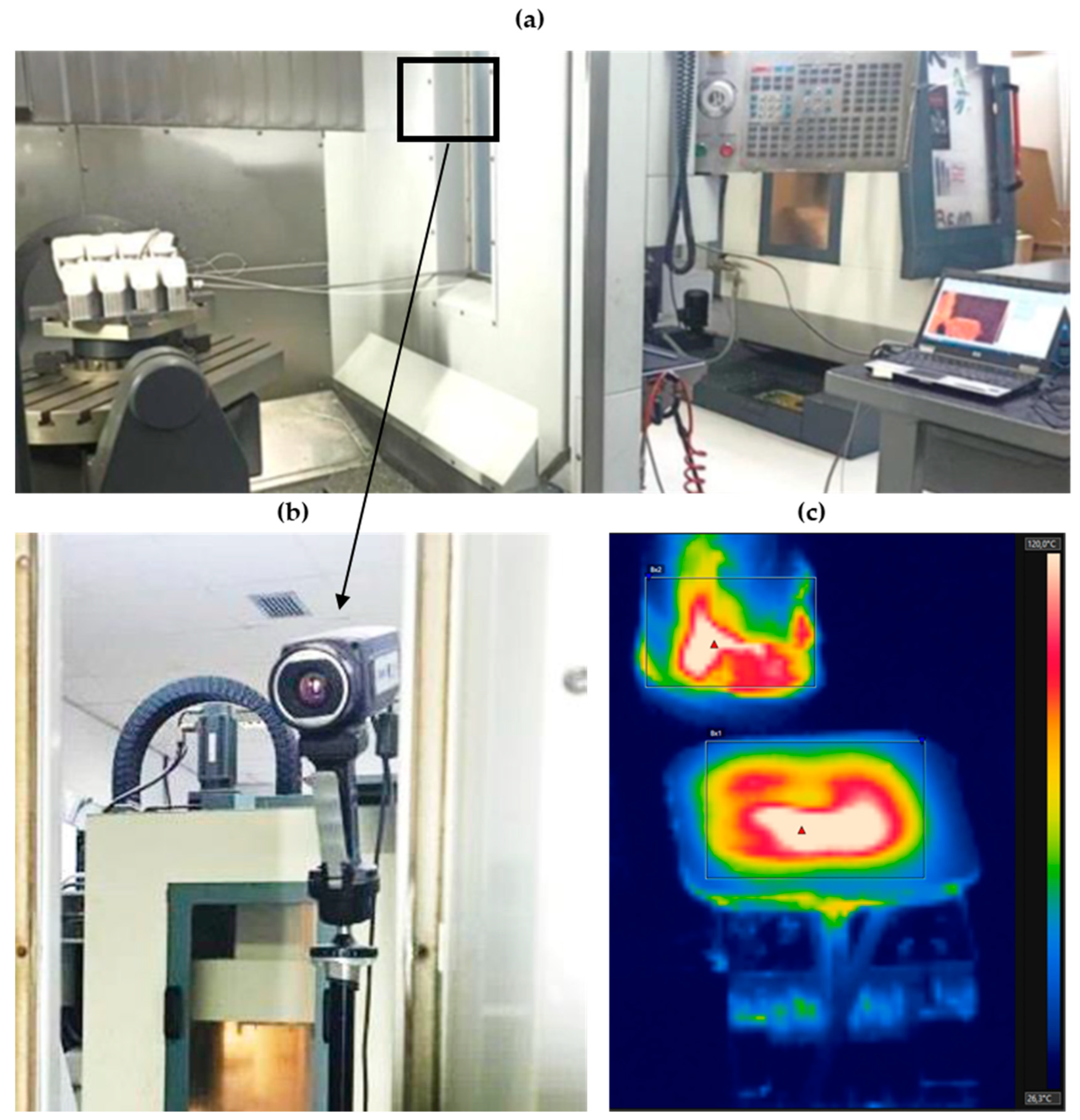
Figure 5a shows the experimental setup with the five-axis CNC machining center, the HAAS UMC-750. On one side, the data acquisition computer can be seen, while inside the HAAS UMC-750, the SLM component and the black square indicating the location of the infrared camera for capturing infrared images are visible. The window glass of the five-axis CNC machining center was removed to ensure clear IR imaging without any interference. The FLIR SC645 high-resolution LWIR science-grade infrared camera (Figure 5b) features an uncooled microbolometer detector with a resolution of 640 × 480 pixels, a 17-micron pixel size, and a spectral detection range of 7.5–13 µm. The thermal camera operates at a frame rate of 25 Hz and within a temperature range of 120 °C to 650 °C. Figure 5c shows an example of an infrared image obtained using the FLIR SC645. To determine the emissivity of the titanium samples during milling trials, laboratory tests were conducted. A machined titanium sample with an attached thermocouple was heated to 650 °C. Then, the thermographic camera was used to measure temperature variations and the cooling process, which were correlated with the appropriate emissivity values to match the thermocouple readings. The 0.30 emissivity for the Ti6Al4V was determined, and it is consistent with references, which place it in the range of 0.20 and 0.35 [19,27]. At the start of the experiments, the distance from the sample to the IR camera, as well as the environmental temperature and humidity, were measured and assumed to remain constant throughout all tests. The reflected temperature was determined using the reflection methodology specified in ASTM E1862-14.
The infrared camera measurements were conducted in situ without interference from chips or tool-workpiece interaction, as the machined area and cutting tool were sufficiently large to ensure accurate temperature registration (see Figure 5c). In this work, infrared images were used to measure and present the maximum temperature, as the thermal effect plays a crucial role in metal machining. Tool life and surface quality largely depend on the maximum temperature reached in the cutting region [16,19].

3. Results and Discussion

3.1. Setup 1: Effect of Cutting Parameters on Surface Roguhness and Temperature

Surface finish is a critical aspect of machining and milling processes, not only because it affects the final aesthetic appearance of the component and its functionality, but also because it provides reliable insights into the condition of the cutting tool. Furthermore, changes in the cutting tool’s condition can lead to significant variations in the temperature reached during the milling process, both on the surface of the component and the tool itself. The results of the experimental Setup 1 (cutting tool XDLX 09T308ER-F40 CTC5240 and the tool holder GA SD090 C 032 Z3), previously described, are presented below. In this setup, the component was rigidly fixed in a vise to analyze how variations in feed per tooth (Fz) and axial depth of cut (Ap) affect surface roughness and temperature changes. The most reliable temperature data was recorded during the second and third passes, where the cutting tool maintained full contact with the component. These two passes were used to draw conclusions and establish correlations between surface roughness, temperature, and cutting tool damage.
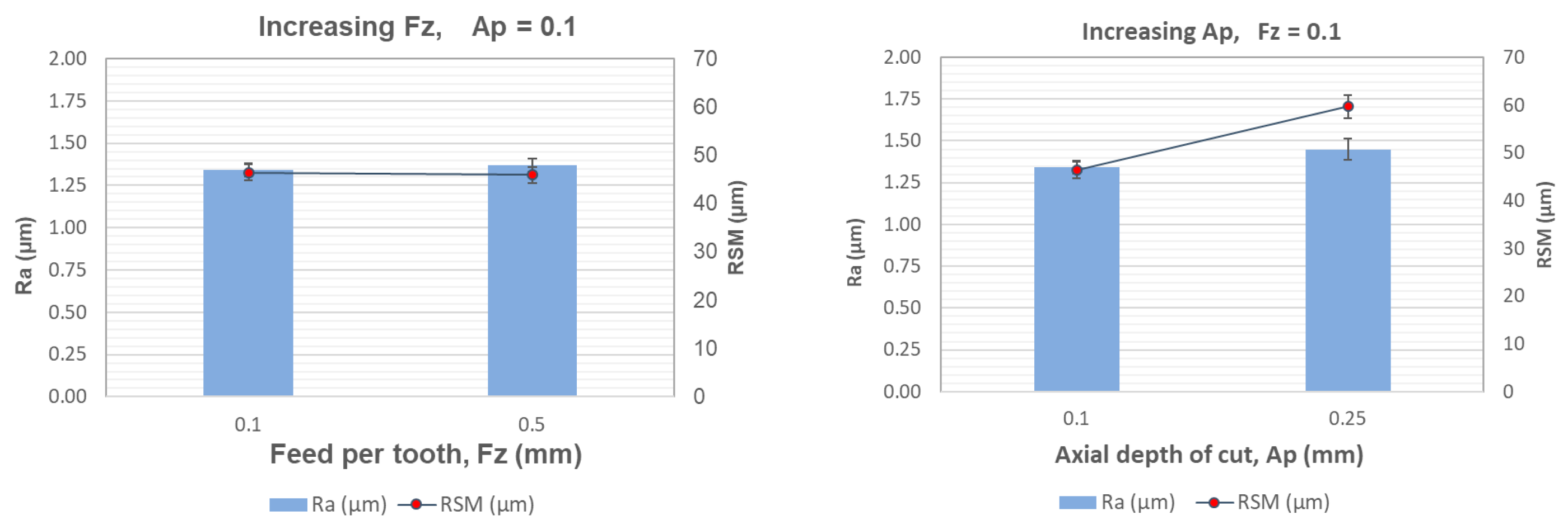
Figure 6 and Table 3 show how the roughness parameters Ra and RSM, as well as the maximum temperature changes during the four milling passes, are affected by the increase in Fz and Ap. It was observed that increasing the Fz parameter 0.1 and 0.5 mm had no significant effect on either surface roughness or temperature. In contrast, increasing Ap from 0.1 to 0.25 mm caused a marked degradation, particularly in the RSM roughness parameter. The measured roughness parameters of Ra were consistent and comparable with other references [24,28], where milling was performed under dry conditions. Moreover, the maximum temperature obtained with the Fp and Az 0.1 values is similar to the ones obtained in [19], but for this reference, the machining was the turning, not the milling, as it is focused on work.
During test number 3, infrared temperature recordings revealed that fixing Ap at 0.25 mm led to a sudden rise in temperature on both the component and the cutting tool. This temperature surge was primarily attributed to the accumulation of titanium swarf or chips, which in turn accelerated tool wear. As a result, the fourth milling pass could not be completed, and the test was halted after the third pass.

3.1.1. Trajectory Changes Affectation

Next, the effect of trajectory changes on the machining process was specifically analyzed. Different milling trajectories, including linear, trochoidal, and helicoidal, were evaluated to determine their impact on surface roughness, temperature, and tool wear.
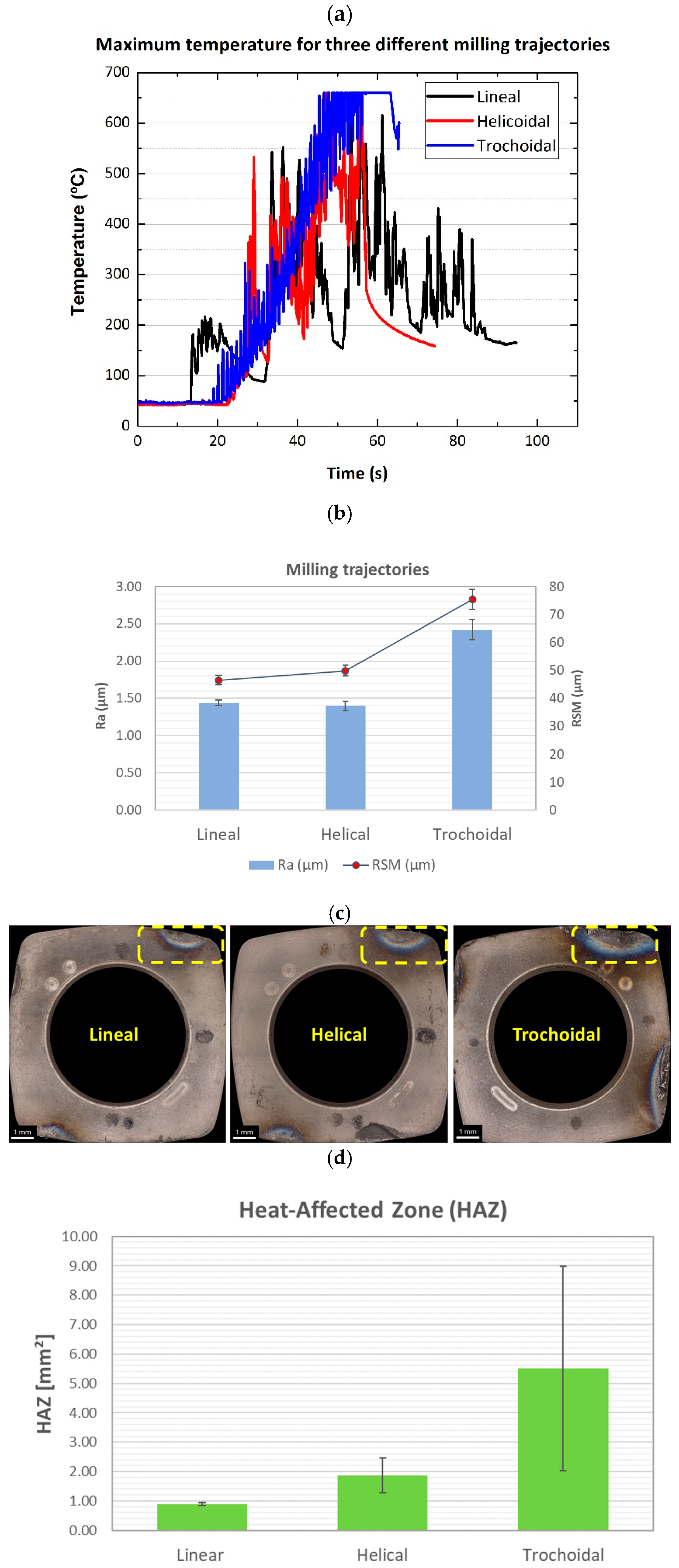
Figure 7a illustrates the maximum temperatures recorded during the milling process for different trajectories. These temperatures significantly influenced the distribution of cutting forces and the heat generated during machining. Specifically, lineal and helicoidal trajectories were found to provide better cooling and reduced tool wear, whereas trochoidal trajectories led to higher temperatures and increased tool damage under similar cutting conditions. Consequently, the machining process using the trochoidal trajectory had to be halted to prevent catastrophic damage to the cutting tool, holder, and component.
These increased temperatures appeared to correlate with higher resulting workpiece roughness. Figure 7b presents the roughness parameters measured on the component surface for the different milling trajectories, showing a major increase for the trochoidal path. Both Ra and RMS increase by an approximate 50%, a significant deterioration in surface finish.
Similar observations could be drawn for the degradation of the workpiece.The Heat-Affected Zone (HAZ) on the cutting tool edge corresponding to each trajectory is illustrated, along with a chart representing the HAZ extent, in Figure 7c,d. Results show a clear increase in the extent of the HAZ for the machining bits used in the trochoidal path experiment (almost 6 mm), with the linear path keeping the minimal HAZ (1 mm), and spiral path an intermediate value (2 mm).
As a conclusion, the trochoidal trajectory can be dismissed as a feasible option for achieving the most efficient and effective machining process in Setup 1, as it appears to result in the most heat being released and the worst workpiece surface quality.

3.1.2. Influence of Cutting Tool Wear on Recorded Temperature

The wear of the cutting tool significantly impacts the temperature measurements recorded during the machining process. As the cutting tool experiences wear, its efficiency in material removal decreases, leading to higher friction and increased heat generation at the tool-workpiece interface.
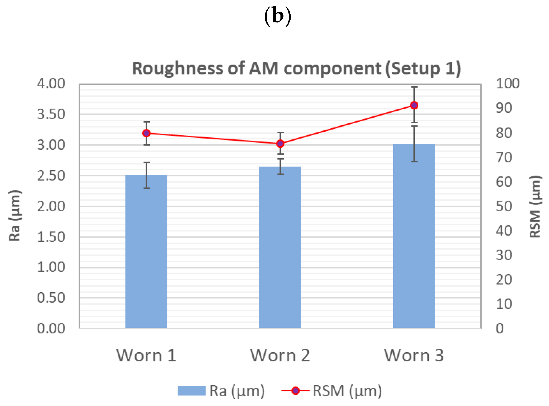
Worn tools tend to produce inconsistent temperature data due to uneven heat distribution and reduced cutting performance. These inconsistencies can compromise the reliability of thermal analysis and its correlation with surface roughness and machining efficiency. In contrast, the thermal gradients were accurately measured by the infrared camera even as the cutting tool wore down. Figure 8a shows the correlation between three different levels of cutting tool wear and the corresponding temperature changes. The chart illustrates three levels of cutting tool wear, labeled as Worn 1, 2, and 3, where a higher number indicates more severe wear on the tool. To clarify, Worn 1 indicates that the milling was performed using a cutting tool that had already undergone wear from one previous round of milling, Worn 2 refers to milling performed with a tool that had experienced wear from two previous rounds of milling, and Worn 3 corresponds to milling performed with a tool that had already undergone wear from three previous rounds of milling. Additionally, Figure 8b illustrates the increase in roughness parameters (Ra and RSM), particularly in the final stage of tool wear (Worn 3). It can be observed that increased cutting tool wear leads to higher temperatures recorded by the infrared camera, accompanied by a rise in roughness parameters due to poorer surface finish quality.
This highlights that the infrared measurements provide consistent values, enabling effective monitoring of tool wear throughout machining operations, which directly affects the surface finish of the component. This behavior showed a strong correlation with the literature, which indicates that excessive wear on the cutting tool directly contributes to an increase in maximum temperature during the machining process [29].

3.2. Setup 2: Effect of Cutting Parameters on Surface Roughness and Temperature Compared with Setup 1

At this stage, it became clear that an improvement in the cutting tool was necessary to achieve an adequate milling process and ensure high surface quality in the thin-wall component. Although the linear trajectory is a widely used technique in the industry and has been validated in multiple studies for block samples and solid plane surfaces—showing correct results in terms of surface finish, tool wear, and heat-affected zone (HAZ) in the previous section—it was insufficient for milling the thin-wall component.
The need for an improved setup (Setup 2) arose due to the complexities associated with milling a component with thin-wall support. As mentioned in the introduction, additional challenges such as vibrations (chatter) and significant displacements of both the cutter and the workpiece posed major obstacles. Chatter, in particular, proved to be a critical drawback that made milling with a linear trajectory unfeasible.
To address this issue, alternative approaches were explored in the literature. Studies [30,31,32,33,34] highlight trochoidal trajectory as an effective path-planning strategy. This technique has the potential to increase the material removal rate per unit of tool wear, thereby enhancing productivity while reducing cutting energy consumption and improving tool performance. Based on these references, the trochoidal trajectory was evaluated and found to be optimal for minimizing vibrations in the 3D-printed thin-wall support component without rigid clamping during the milling process, ultimately improving process stability and surface quality.
Setup 2 utilized the cutting tool T290 LNMT 100405TR IC808 with the tool holder T290 ELN D20-03-W20-10. This cutting tool featured a combined TiAlN+TiN coating, selected because this multilayer coatings generally deliver superior performance across various applications compared to monolayer and uncoated tools [35,36]. Tests were conducted on both a rigidly fixed component using a vise and a 3D-printed thin-wall support without rigid clamping, using a trochoidal trajectory. The feed per tooth (Fz) and axial depth of cut (Ap) were fixed at 0.1 mm throughout.
The primary change in cutting parameters compared to Setup 1 was an increase in cutting velocity (Vc) to 120 m/min—double that of Setup 1—necessitated by the cutting tool’s minimum requirements as specified by the supplier. The tool holder in Setup 2 also supported three effective edges (Zc = 3).
This section includes a comparison of the results from Setup 2 and Setup 1. Initially, the analysis focused on the impact of reducing the tool diameter from 32 mm to 20 mm. Subsequently, the relationship between tool damage, temperature changes, and their effects on surface roughness was examined for both setups. Finally, Setup 2 was used to evaluate tool wear and surface quality differences between a rigidly fixed component, and one supported by the 3D-printed thin-wall structure.

3.2.1. Diameter Change: Setup 1 vs. Setup 2

Figure 9 illustrates the maximum temperature measurements recorded by the infrared camera for the SLM component rigidly fixed with a vise. The results demonstrate that Setup 2 exhibited significantly better thermal performance compared to Setup 1 when employing a trochoidal trajectory. Setup 1 displayed a critical temperature increase exceeding 660 °C, whereas Setup 2 maintained temperatures under 250 °C throughout the milling process. To determine whether the key improvement in Setup 2 was primarily due to the reduction in tool diameter or the advanced coating in the cutting tool, a literature review was conducted. A study [29] demonstrated that using a 32 mm diameter tool with advanced coatings improved machinability, which has a direct impact on the maximum temperature during the milling process. Additionally, another study [37] showed that changes in tool diameter had no significant effect on average surface roughness. This suggests that while diameter reduction may have influenced the process, the primary factor in lowering maximum temperatures was the correct selection of the advanced coating of the cutting tool in Setup 2, which reduces the coefficient of friction. Maintaining lower temperatures ensures improved surface roughness, as detailed in the following subsection.

3.2.2. Influence of Cutting Tool Wear: Setup 1 vs. Setup 2

Figure 10 shows the correlation between three different levels of cutting tool wear and the corresponding roughness parameters (Ra and RSM) for Setup 1 and Setup 2. While the roughness parameters increase with the progression of tool wear in Setup 1, Setup 2 maintains consistent Ra and RSM values. This is because the cutting tools in Setup 2 experienced less wear, despite both setups having the same workload. The comparison of cutting tool damage is provided in detail in the following section.

3.2.3. Damage in the Cutting Tools: Setup 1 vs. Setup 2

Figure 11 displays an example of the 3D overlapped images used to measure the adhered and removed material of the cutting edge of tools. The color thresholding technique is used to represent the differences in terms of picks (adhered material) or valleys (removed material). The yellow and aqua colors indicate the initial surface of tools corresponding to Setup 1 and Setup 2, respectively. In both cases, the valley areas are represented with blue/magenta colors, where tool of Setup 1 achieved deeper values (~600 mm) than Setup 2 (~80 mm). The bar graph shown in Figure 11 corresponds to the measurements of all worn tools evaluated in this work for both setups. In this case, the quantification of removed and adhered material is expressed in terms of volume (mm3). Results indicate that tools used in Setup 1 presented a higher volume of worn material, which is visible in 3D images as chipping and spalling of large particles at the cutting edge. Even more, the volume of adhered material was also higher than the tools of Setup 2. These phenomena can be attributed to the severe machining conditions, where high temperatures were achieved (around 600 °C), as shown in Figure 9, promoting the tool brittleness.

3.2.4. Comparison of Vise Fixation vs. 3D-Printed Thin-Wall Support for Setup 2

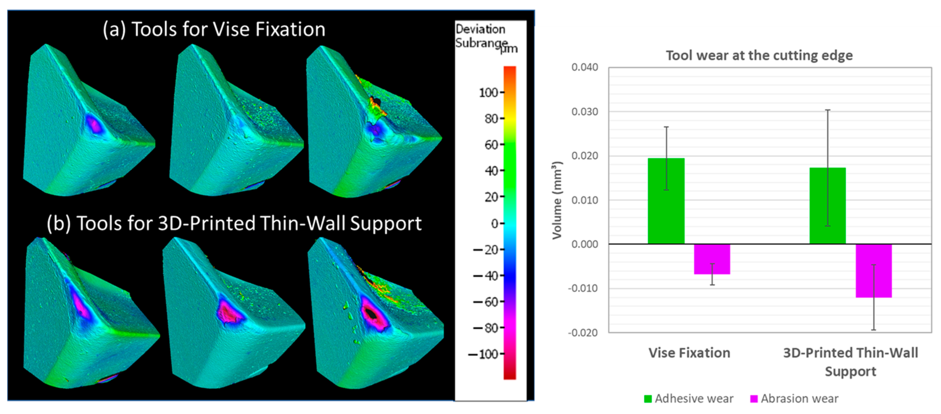
In this final subsection, the effect of fixing the component with a vise versus using its own 3D-printed thin-wall support was analyzed. Figure 12 shows 3D images of the cutting edge for both conditions using Setup 2. As observed, both tools exhibit good performance compared to Setup 1 (as shown in Figure 11), whether fixed with the vise or the thin-wall support. However, the second condition, using the 3D-printed thin-wall support, showed an increased wear on the cutting tool. In this case, magenta colors show the deepest values (~100 mm) for the 3D-printed thin-walled supported component. Even with the use of coated tools, these dry machine conditions induced premature damage, and it is attributed to the presence of higher vibrations.
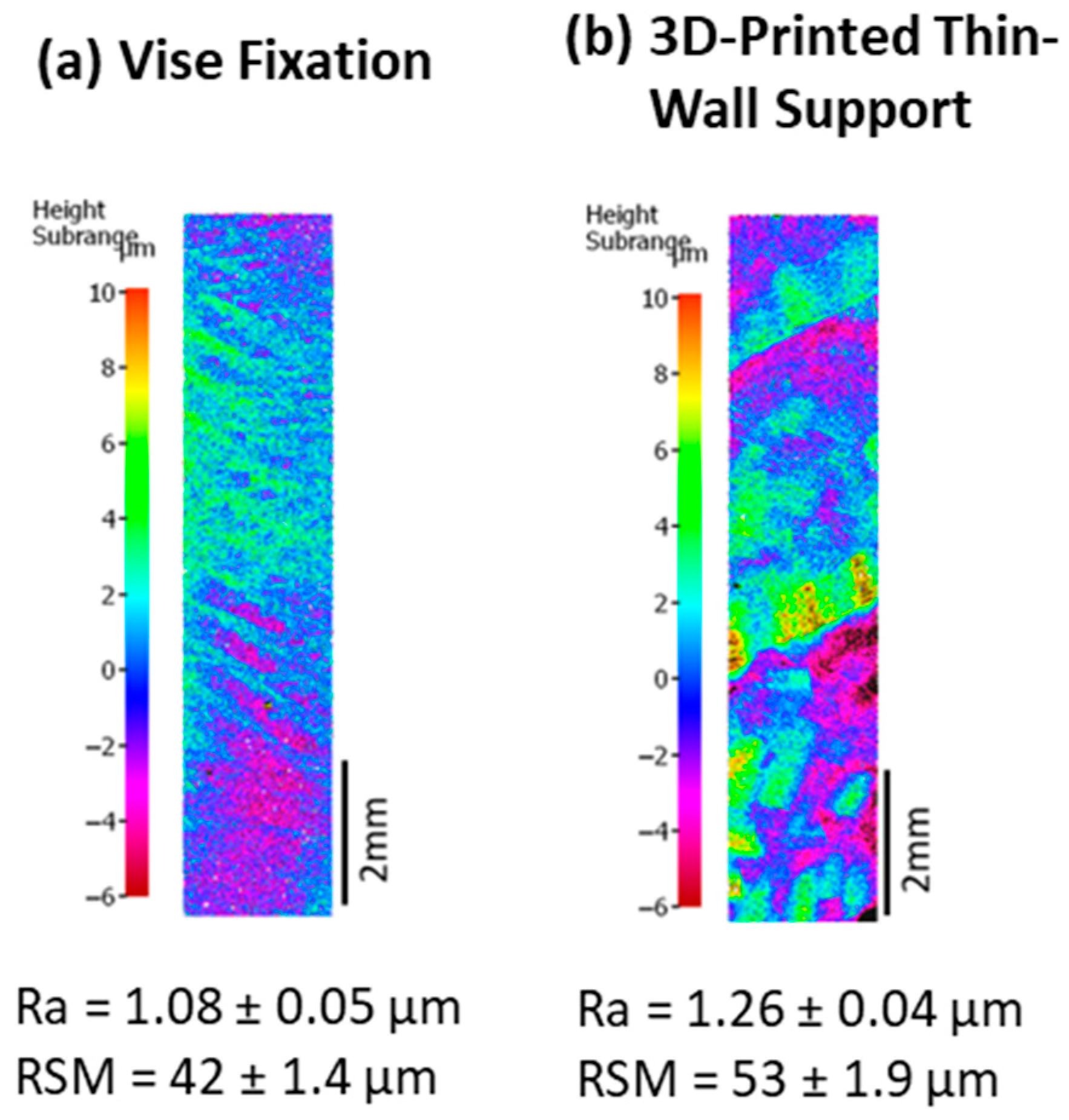
The vibrations and early wear of the cutting tool were also reflected in the surface roughness of the milled component (Figure 13). In this case, the differences were discerned in the surface patterns and machining patterns (3D profilometer images) and in terms of the mean width of profile elements (RSM), since it reflects the arithmetic mean value of the widths of the profile elements of the roughness profile, where a profile element is a peak and valley in the roughness profile. This value tends to increase in the thin-wall-supported component due to the increment of vibrations attributed to the fixing system, as also seen in the patterns of the surface roughness.
The stability of the system is a critical factor to consider in any machining process, as it helps prevent undesired damage to the tool and ensures a high-quality surface finish.
Despite the complexity of machining a thin-wall support 3D AM component, the final Ra parameter of 1.26 ± 0.04 µm met aeronautical industry requirements. While the general requirement specifies a surface roughness average (Ra) of 3.2 µm, more demanding areas require an Ra of 1.6 µm. These standards are based on the internal Airbus specification CAN 16056.

4. Conclusions

This study explored post-machining alternatives for thin-walled additive-manufactured components, utilizing an infrared thermographic monitoring system to correlate and identify tool damage and poor surface finishes in machining processes. This analysis was performed in the context of sustainable manufacturing, as the post-machining was performed under dry conditions. More importantly, this work demonstrated that the complexity of thin-wall support in AM components determines both the machining trajectory and the achievable surface roughness quality.
It has been demonstrated that a cutting tool with a coating designed for machining titanium in Setup 1 produced valid results when used with a linear milling trajectory for the additive-manufactured component fixed in a vise. However, when the component was no longer solidly fixed in the vise and was instead supported only by the thin-walled structure, the linear and helical trajectories were no longer effective. This required a new approach, and by using a trochoidal trajectory combined with a multilayer-coated cutting tool, reliable results were achieved. Additional and more detailed conclusions drawn from this work include:
  • Changes in feed per tooth (Fz) and axial depth of cut (Ap) significantly influence tool wear and temperature. While varying Fz and change in diameter of the cutting tool did not have a major impact, increasing Ap led to more noticeable tool degradation, especially in terms of surface roughness. In future works, optimizing these parameters can lead to more energy-efficient and environmentally friendly machining processes.
  • Among the two roughness parameters, Ra (arithmetic average roughness) and RSM (root mean square roughness), the RSM parameter proved to be more sensitive and reliable in detecting surface finish differences. As a result, it is considered more dependable for comparison with infrared camera temperature readings, offering a precise method for monitoring sustainability-driven improvements in surface finish quality.
  • For Setup 1, it was shown that the linear and helicoidal trajectories provided better cooling and reduced tool wear compared to trochoidal trajectories. Trochoidal paths resulted in higher temperatures and more severe tool damage, indicating that optimizing cutting trajectories can lead to more energy-efficient and sustainable production processes.
  • In Setup 2, it was demonstrated that the method of fixing the component, whether with a vise or a 3D-printed thin-wall support, had an effect on tool performance. The 3D-printed support led to increased tool wear, potentially due to vibrations during the milling process. However, both methods performed better than Setup 1, emphasizing the role of material and system stability in optimizing energy use and process sustainability.
  • As cutting tool wear/damage increased, infrared temperature readings showed a rise in temperature, which correlated with increased RSM roughness value of the Ti-6Al-4V surface parameters due to the increment of vibrations to worsened surface finishes. These findings underscore the importance of minimizing tool wear to enhance operational efficiency and reduce material waste.
  • The use of infrared cameras has been confirmed as an effective tool for monitoring tool condition and surface quality, especially in dry machining conditions, where traditional lubrication is absent. This technique aids in detecting temperature increases that signal potential issues, such as tool wear or surface roughness degradation, while promoting more sustainable practices by eliminating the need for chemical lubricants.
The stability of the machining system is crucial in preventing tool damage and achieving optimal surface finishes. Any instability, such as vibrations, can lead to increased wear and poor component quality. Ensuring system stability not only improves tool life and part quality but also supports more sustainable, cost-effective manufacturing practices.
Future studies at pilot plants or industrial levels will be necessary to evaluate the economic feasibility of the dry milling process, considering the savings from not using lubricants, as well as the increased wear on the tool and the surface finish for thin-wall support 3D AM complex structures presented in this work.

Author Contributions

Conceptualization, G.R., M.F. and E.G.-L.; Methodology, G.R., E.V. and E.G.-L.; Validation, G.R. and E.G.-L.; Formal Analysis, G.R., E.V. and E.G.-L.; Investigation, G.R., M.F. and E.G.-L.; Resources, G.R. and M.F.; Data Curation, G.R., E.V. and E.G.-L.; Writing—Original Draft Preparation, E.G.-L.; Writing—Review & Editing, G.R., J.P. and E.G.-L.; Visualization, G.R., J.P., M.F., E.V. and E.G.-L.; Supervision, J.P. and G.R.; Project Administration, G.R.; Funding Acquisition, G.R. and J.P. All authors have read and agreed to the published version of the manuscript.

Funding

This research was funded by Ministry of Science and Innovation through the 2019 CIEN call as well as by the Catalan Government via the ACCIÓ-Eurecat TRAÇA-IMPULSENS funding grant.

Data Availability Statement

The original contributions presented in this study are included in the article. Further inquiries can be directed to the corresponding authors.

Acknowledgments

This work was performed inside the project LUBRINTEL, which received fundings from CDTI and supported by the Ministry of Science and Innovation through the 2019 CIEN call. Moreover, this work was financially supported by the Catalan Government through the funding grant ACCIÓ-Eurecat TRAÇA-IMPULSENS.

Conflicts of Interest

The authors declare no conflicts of interest.

References

  1. Peters, M.; Hemptenmacher, J.; Kumpfert, J.; Leyens, C. Structure and Properties of Titanium and Titanium Alloys; Wiley-VCH Verlag GmbH & Co., KGaA: Weinheim, Germany, 2003; pp. 1–36. [Google Scholar] [CrossRef]
  2. Srivastava, M.; Jayakumar, V.; Udayan, Y.; Sathishkumar, M.; Muthu, S.M.; Gautam, P.; Nag, A. Additive manufacturing of Titanium alloy for aerospace applications: Insights into the process, microstructure, and mechanical properties. Appl. Mat. Today 2024, 41, 102481. [Google Scholar] [CrossRef]
  3. Nguyen, H.D.; Pramanik, A.; Basak, A.K.; Dong, Y.; Prakash, C.; Debnath, S.; Shankar, S.; Jawahir, I.S.; Dixit, S.; Buddhi, D. A critical review on additive manufacturing of Ti-6Al-4V alloy: Microstructure and mechanical properties. J. Mater. Res. Technol. 2022, 18, 4641–4661. [Google Scholar] [CrossRef]
  4. Al-Rubaie, K.S.; Melotti, S.; Rabelo, A.; Paiva, J.M.; Elbestawi, M.A.; Veldhuis, S.C. Machinability of SLM-produced Ti6Al4V titanium alloy parts. J. Manuf. Process. 2020, 57, 768–786. [Google Scholar] [CrossRef]
  5. Ni, C.; Zhu, L.; Zheng, Z.; Zhang, J.; Yang, Y.; Hong, R.; Bai, Y.; Lu, W.F.; Wang, H. Effects of machining surface and laser beam scanning strategy on machinability of selective laser melted Ti6Al4V alloy in milling. Mater. Des. 2020, 194, 108880. [Google Scholar] [CrossRef]
  6. Boyer, R.R. An overview on the use of titanium in the aerospace industry. Mater. Sci. Eng. A 1996, 213, 103–114. [Google Scholar] [CrossRef]
  7. Kishawy, H.A.; Hosseini, A. Machining Difficult-to-Cut Materials Basic Principles and Challenges; Springer: Oshawa, ON, Canada, 2019. [Google Scholar] [CrossRef]
  8. Pimenov, D.Y.; Mia, M.; Gupta, M.K.; Machado, A.R.; Tomaz, I.V.; Sarikaya, M.; Wojciechowski, S.; Mikolajczyk, T.; Kapłonek, W. Improvement of machinability of Ti and its alloys using cooling-lubrication techniques: A review and future prospect. J. Mater. Res. Technol. 2021, 11, 719–753. [Google Scholar] [CrossRef]
  9. Shokoohi, Y.; Khosrojerdi, E.; Rassolian Shiadhi, B.H. Machining and ecological effects of a new developed cutting fluid in combination with different cooling techniques on turning operation. J. Clean. Prod. 2015, 94, 330–339. [Google Scholar] [CrossRef]
  10. Samukov, A.; Cherkasova, M.; Kuksov, M.; Dmitriev, S. Metal chips preparation for utilization using advanced reagents. In IOP Conference Series: Earth and Environmental Science; IOP Publishing: Bristol, UK, 2021; Volume 938, p. 012009. [Google Scholar] [CrossRef]
  11. Lei, Y.; Zhang, Y.; Newkirk, J.W.; Liou, F.; Thomas, E.; Baker, A. Investigation of Machining Coolant Residue Cleaning Methods for Ti6Al4V Part Fabrication through Hybrid Manufacturing Process. Manuf. Lett. 2018, 16, 10–13. [Google Scholar] [CrossRef]
  12. Isaev, A.V.; Grechishnikov, V.A.; Petr, P.; Mihail, K.; Yuriy, I.; Andrey, V. Machining of Thin-walled Parts Produced by Additive Manufacturing Technologies. Procedia cIRP 2016, 41, 1023–1026. [Google Scholar] [CrossRef]
  13. Pegues, J.; Roach, M.; Williamson, R.S.; Shamsaei, N. Surface roughness effects on the fatigue strength of additively manufactured Ti-6Al-4V. Int. J. Fatigue 2019, 116, 543–552. [Google Scholar] [CrossRef]
  14. Bin Anwar Fadzil, A.F.; Pramanik, A.; Basak, A.K.; Prakash, C.; Shankar, S. Role of surface quality on biocompatibility of implants—A review. Ann. 3D Print. Med. 2022, 8, 100082. [Google Scholar] [CrossRef]
  15. Rahulan, N.; Sreekala Sharma, S.; Rakesh, N.; Sambhu, R. A short review on mechanical properties of SLM titanium alloys based on recent research works. Mater. Today. 2022, 56, A7–A12. [Google Scholar] [CrossRef]
  16. Zgórniak, P.; Stachurski, W.; Ostrowski, D. Application of Thermographic Measurements for the Determination of the Impact of Selected Cutting Parameters on the Temperature in the Workpiece During Milling Process. J. Mech. Eng. 2016, 62, 657–664. [Google Scholar] [CrossRef]
  17. Ramirez-Nunez, J.A.; Trejo-Hernandez, M.; Romero-Troncoso, R.J.; Herrera-Ruiz, G.; Osornio-Rios, R.A. Smart-sensor for tool-breakage detection in milling process under dry and wet conditions based on infrared thermography. Int. J. Adv. Manuf. Technol. 2018, 97, 1753–1765. [Google Scholar] [CrossRef]
  18. Armendia, M.; Garay, A.; Villar, A.; Davies, M.A.; Arrazola, P.J. High bandwidth temperature measurement in interrupted cutting of difficult to machine materials. CIRP Ann. 2010, 59, 97–100. [Google Scholar] [CrossRef]
  19. De Maddis, M.; Lunetto, V.; Razza, V.; Russo Spena, P. Infrared Thermography for Investigation of Surface Quality in Dry Finish Turning of Ti6Al4V. Metals 2022, 12, 154. [Google Scholar] [CrossRef]
  20. Sales, W.F.; Diniz, A.E.; Machado, A.R. Application of cutting fluids in machining processes. J. Barz. Soc. Mech. Sci. 2001, 23, 224–240. [Google Scholar] [CrossRef]
  21. Khanna, N.; Zadafiya, K.; Patel, T.; Kaynak, Y.; Rashid, R.A.R.; Vafadar, A. Review on machining of additively manufactured nickel and titanium alloys. J. Mater. Res. Technol. 2021, 15, 3192–3221. [Google Scholar] [CrossRef]
  22. Campos, F.O.; Araujo, A.C.; Munhoz, A.L.J.; Kapoor, S.G. The influence of additive manufacturing on the micromilling machinability of Ti6Al4V: A comparison of SLM and commercial workpieces. J. Manuf. Process. 2020, 60, 299–307. [Google Scholar] [CrossRef]
  23. Khaliq, W.; Zhang, C.; Jamil, M.; Khan, A.M. Tool wear, surface quality, and residual stresses analysis of micro-machined additive manufactured Ti–6Al–4V under dry and MQL conditions. Tribol. Int. 2020, 151, 106408. [Google Scholar] [CrossRef]
  24. Zhang, H.; Dang, J.; Ming, W.; Xu, X.; Chen, M.; An, Q. Cutting responses of additive manufactured Ti6Al4V with solid ceramic tool under dry high-speed milling processes. Ceram. Int. 2020, 46, 14536–14547. [Google Scholar] [CrossRef]
  25. X1. UNE-EN ISO 4287; Geometrical product specifications (GPS). Surface texture: Profile method. Terms, definitions and surface texture parameters (ISO 4287:1997 + Technical Corrigendum 1). International Organization for Standardization (ISO): Geneva, Switzerland, 1997.
  26. X2. UNE-EN ISO 25178-2; Geometrical product specifications (GPS)—Surface texture: Areal—Part 2: Terms, definitions and surface texture parameters (ISO 25178-2:2021). International Organization for Standardization (ISO): Geneva, Switzerland, 2021.
  27. González-Fernández, L.; Risueño, E.; Pérez-Sáez, R.B.; Tello, M.J. Infrared normal spectral emissivity of Ti–6Al–4V alloy in the 500–1150 K temperature range. J. Alloys Compd. 2012, 541, 144–149. [Google Scholar] [CrossRef]
  28. Veiga, F.; Del Val, A.G.; Suárez, A.; Alonso, U. Analysis of the Machining Process of Titanium Ti6Al-4V Parts Manufactured by Wire Arc Additive Manufacturing (WAAM). Materials 2020, 13, 766. [Google Scholar] [CrossRef]
  29. Jaffery, S.H.; Khan, M.; Nadeem A Sheikh, N.A.; Mativenga, P. Wear mechanism analysis in milling of Ti-6Al-4V alloy. Proc. Inst. Mech. Eng. Part B J. Eng. Manuf. 2013, 227, 1148–1156. [Google Scholar] [CrossRef]
  30. Niaki, F.A.; Pleta, A.; Mears, L.; Potthoff, N.; Bergmann, J.A.; Wiederkehr, P. Trochoidal milling: Investigation of dynamic stability and time domain simulation in an alternative path planning strategy. Int. J. Adv. Manuf. Technol. 2019, 102, 1405–1419. [Google Scholar] [CrossRef]
  31. Luo, M.; Hah, C.; Hafeez, H.M. Four-axis trochoidal toolpath planning for rough milling of aero-engine blisks. Chin. J. Aeronaut. 2019, 32, 2009–2016. [Google Scholar] [CrossRef]
  32. Dong, Y.; Li, S.; Zhang, Q.; Li, P.; Jia, Z.; Li, Y. Modeling and Analysis of Micro Surface Topography from Ball-End Milling in a Trochoidal Milling Mode. Micromachines 2021, 12, 1203. [Google Scholar] [CrossRef]
  33. García-Hernández, C.; Garde-Barace, J.-J.; Valdivia-Sánchez, J.-J.; Ubieto-Artur, P.; Bueno-Pérez, J.-A.; Cano-Álvarez, B.; Alcázar Sánchez, M.-Á.; Valdivia-Calvo, F.; Ponz-Cuenca, R.; Huertas-Talón, J.-L.; et al. Trochoidal Milling Path with Variable Feed. Application to the Machining of a Ti-6Al-4V Part. Mathematics 2021, 9, 2701. [Google Scholar] [CrossRef]
  34. Zhou, X.; Zhou, J.; Qi, Q.; Zhang, C.; Zhang, D. Effects of Toolpath Parameters on Engagement Angle and Cutting Force in Ellipse-Based Trochoidal Milling of Titanium Alloy Ti-6Al-4V. Appl. Sci. 2023, 13, 6550. [Google Scholar] [CrossRef]
  35. Sousa, V.F.C.; Silva, F.J.G. Recent Advances on Coated Milling Tool Technology—A Comprehensive Review. Coatings 2020, 10, 235. [Google Scholar] [CrossRef]
  36. Zhao, J.; Liu, Z.; Wang, B.; Hu, J.; Wan, Y. Tool coating effects on cutting temperature during metal cutting processes: Comprehensive review and future research directions. Mech. Syst. Signal Process. 2021, 150, 107302. [Google Scholar] [CrossRef]
  37. Harun, S.; Burhanuddin, Y.; Ibrahim, G.A. The Effect of Cutting Parameters on Surface Roughness and Morphology of Ti-6Al-4V ELI Titanium Alloy during Turning with Actively Driven Rotary Tools. J. Manuf. Mater. Process. 2022, 6, 105. [Google Scholar] [CrossRef]
Figure 1. Schematic of the SLM component machined by milling process in this study, along its dimensions.
Processes 13 00717 g001
Figure 2. (a) Image of cutting tool XDLX 09T308ER-F40 CTC5240 and the tool holder GA SD090 C 032 Z3; (b) Image of cutting tool T290 LNMT 100405TR IC808 and the tool holder T290 ELN D20-03-W20-10.
Processes 13 00717 g002
Figure 3. Scheme of the three different trajectories used in the tests.
Processes 13 00717 g003
Figure 4. From left to right, the figure shows the machined component with the analyzed surface highlighted by a black rectangle, followed by the extracted 3D image and the graph illustrating the surface roughness variation.
Processes 13 00717 g004
Figure 5. (a) Experimental setup with the five-axis CNC machining center, the HAAS UMC-750. Inside, the SLM component is visible, and the black square indicates the location of the infrared camera; (b) FLIR SC645 high-resolution LWIR infrared camera; (c) Example of an infrared image acquired by the infrared camera. The two registered temperature areas are represented by two rectangles. The bottom rectangle focuses on the component temperature, while the top rectangle focuses on the tool temperature. The red triangles indicate the maximum temperature in each area.
Processes 13 00717 g005
Figure 6. Variation of Ra and RSM roughness parameters while keeping Ap fixed at 0.1 and increasing Fz with values of 0.1 and 0.5 (left chart), and while keeping Fz fixed at 0.1 and increasing Ap with values of 0.1 and 0.25 (right chart).
Processes 13 00717 g006
Figure 7. (a) The chart shows the maximum temperatures recorded during the milling process for different trajectories. (b) Surface roughness parameters measured on the component for different milling trajectories. (c) Image of the heat-affected zone (HAZ) on the cutting tool edge (highlighted in a yellow square) for the various trajectories, along with a chart (d) illustrating the extent of the HAZ.
Processes 13 00717 g007
Figure 8. (a) Correlation between three levels of cutting tool wear and the corresponding maximum temperature changes measured by the infrared camera. (b) Evolution of Ra and RSM roughness of the AM component obtained with the three levels of tool wear.
Processes 13 00717 g008aProcesses 13 00717 g008b
Figure 9. Temperature evolution recorded by the infrared camera for Setup 1 and Setup 2 during the milling process with a trochoidal trajectory.
Processes 13 00717 g009
Figure 10. Evolution of Ra and RSM roughness parameters with the three levels of tool wear for Setup 1 and Setup 2.
Processes 13 00717 g010
Figure 11. At (left), 3D images of the worn cutting tools for Setup 1 and for Setup 2 are shown. At the (right), charts depicting tool damage, including adhesion and wear, are presented.
Processes 13 00717 g011
Figure 12. On the (left), images of the cutting tools for the compound fixed with a vise and the compound with 3D-printed thin-wall support, both for Setup 2, are shown. On the (right), a chart depicting tool damage, including adhesion and wear, is presented.
Processes 13 00717 g012
Figure 13. Three-dimensional surface images of the milled, 3D-printed Ti-6Al-4V surface fixed with the (a) vise and (b) thin-walled supported for Setup 2 and the Ra and RSM roughness values.
Processes 13 00717 g013
Table 1. Chemical composition of the Ti-6Al-4V powder for SLM, compared to ASTM B265 Ti6Al4V grade alloy [5]; amounts in [wt%].
TiAlVFeOCNHRes.
Ti6Al4V powder for SLMBalance5.5–6.53.5–4.5≤0.25≤0.13≤0.08≤0.05≤0.012≤0.41
ASTM B265 Ti6Al4V alloyBalance5.5–6.753.5–4.5≤0.4≤0.2≤0.08≤0.05≤0.015≤0.40
Table 2. Summary of the variation parameters feed per tooth (Fz) and axial depth of cut (Ap) and trajectory for each test.
Test NumberAp (mm)Fz (mm)Trajectory
10.10.1Linear
20.10.5Linear
30.250.1Linear
40.10.1Trochoidal
50.10.1Helical
Table 3. Maximum temperatures recorded during the four milling passes for the material and tool under varying feed per tooth (Fz) and axial depth of cut (Ap).
Test NumberAp (mm)Fz (mm)Ra (µm)RSM (µm)PassesMax. Temperature (°C)
MaterialTool
10.10.11.34 ± 0.0446 ± 1.71st 20393
2nd552184
3rd615217
4rt414189
20.10.51.37 ± 0.0446 ± 1.71st 42390
2nd471159
3rd567159
4rt462155
30.250.11.45 ± 0.0660 ± 2.51st 650280
2nd<660325
3rd<660388
Disclaimer/Publisher’s Note: The statements, opinions and data contained in all publications are solely those of the individual author(s) and contributor(s) and not of MDPI and/or the editor(s). MDPI and/or the editor(s) disclaim responsibility for any injury to people or property resulting from any ideas, methods, instructions or products referred to in the content.